EP2592005A1 - System for dispensing hazardous fluids into vials - Google Patents
System for dispensing hazardous fluids into vials Download PDFInfo
- Publication number
- EP2592005A1 EP2592005A1 EP11189064.6A EP11189064A EP2592005A1 EP 2592005 A1 EP2592005 A1 EP 2592005A1 EP 11189064 A EP11189064 A EP 11189064A EP 2592005 A1 EP2592005 A1 EP 2592005A1
- Authority
- EP
- European Patent Office
- Prior art keywords
- container
- septum
- needles
- delivery
- container holder
- Prior art date
- Legal status (The legal status is an assumption and is not a legal conclusion. Google has not performed a legal analysis and makes no representation as to the accuracy of the status listed.)
- Withdrawn
Links
Images



Classifications
-
- B—PERFORMING OPERATIONS; TRANSPORTING
- B65—CONVEYING; PACKING; STORING; HANDLING THIN OR FILAMENTARY MATERIAL
- B65B—MACHINES, APPARATUS OR DEVICES FOR, OR METHODS OF, PACKAGING ARTICLES OR MATERIALS; UNPACKING
- B65B3/00—Packaging plastic material, semiliquids, liquids or mixed solids and liquids, in individual containers or receptacles, e.g. bags, sacks, boxes, cartons, cans, or jars
- B65B3/003—Filling medical containers such as ampoules, vials, syringes or the like
-
- B—PERFORMING OPERATIONS; TRANSPORTING
- B65—CONVEYING; PACKING; STORING; HANDLING THIN OR FILAMENTARY MATERIAL
- B65B—MACHINES, APPARATUS OR DEVICES FOR, OR METHODS OF, PACKAGING ARTICLES OR MATERIALS; UNPACKING
- B65B3/00—Packaging plastic material, semiliquids, liquids or mixed solids and liquids, in individual containers or receptacles, e.g. bags, sacks, boxes, cartons, cans, or jars
- B65B3/04—Methods of, or means for, filling the material into the containers or receptacles
- B65B3/10—Methods of, or means for, filling the material into the containers or receptacles by application of pressure to material
- B65B3/12—Methods of, or means for, filling the material into the containers or receptacles by application of pressure to material mechanically, e.g. by pistons or pumps
-
- B—PERFORMING OPERATIONS; TRANSPORTING
- B65—CONVEYING; PACKING; STORING; HANDLING THIN OR FILAMENTARY MATERIAL
- B65B—MACHINES, APPARATUS OR DEVICES FOR, OR METHODS OF, PACKAGING ARTICLES OR MATERIALS; UNPACKING
- B65B39/00—Nozzles, funnels or guides for introducing articles or materials into containers or wrappers
- B65B39/12—Nozzles, funnels or guides for introducing articles or materials into containers or wrappers movable towards or away from container or wrapper during filling or depositing
-
- B—PERFORMING OPERATIONS; TRANSPORTING
- B65—CONVEYING; PACKING; STORING; HANDLING THIN OR FILAMENTARY MATERIAL
- B65B—MACHINES, APPARATUS OR DEVICES FOR, OR METHODS OF, PACKAGING ARTICLES OR MATERIALS; UNPACKING
- B65B39/00—Nozzles, funnels or guides for introducing articles or materials into containers or wrappers
- B65B2039/009—Multiple outlets
-
- B—PERFORMING OPERATIONS; TRANSPORTING
- B65—CONVEYING; PACKING; STORING; HANDLING THIN OR FILAMENTARY MATERIAL
- B65B—MACHINES, APPARATUS OR DEVICES FOR, OR METHODS OF, PACKAGING ARTICLES OR MATERIALS; UNPACKING
- B65B31/00—Packaging articles or materials under special atmospheric or gaseous conditions; Adding propellants to aerosol containers
- B65B31/04—Evacuating, pressurising or gasifying filled containers or wrappers by means of nozzles through which air or other gas, e.g. an inert gas, is withdrawn or supplied
- B65B31/08—Evacuating, pressurising or gasifying filled containers or wrappers by means of nozzles through which air or other gas, e.g. an inert gas, is withdrawn or supplied the nozzle being adapted to pierce the container or wrapper
Definitions
- the present invention relates to an apparatus for dispensing a hazardous fluid into a container, especially a vial closed with a septum, with the features of the preamble of claim 1. Furthermore a method for dispensing such hazardous fluids is disclosed as well as a delivering system comprising said apparatus.
- the prior art comprises a number of solutions to dispense a fluid, especially a biohazardous or radioactive fluid into a container.
- the dispensing operation is usually conducted within a protected enclosure, usually made of concrete or of lead in a steel frame as usual in radiopharmacy, having shielded windows and manipulators operated by remote control, used to handle these hazardous especially biologically dangerous or radioactive materials.
- a protected enclosure is named hot cell, especially within the technologies of dispensing radioactive materials but will be used within this specification in the same way for handling bio-hazards.
- US 2010/218846 provides a method and apparatus for a contamination-free transfer of a hazardous liquid from one container to another.
- the aim of this teaching is to avoid any leakage of the liquid or air contaminated by the liquid or vapors of the liquid to the surrounding volume wherein the needles are located within a housing, crossing a first septum and being adapted to pierce a second septum, provided in a predefined distance from the first septum of the device.
- said second septum is in contact with a third septum being part of a vial adaptor, which is attached to the vial which has to receive the hazardous fluid.
- TW 440 879B discloses a liquid target transfer apparatus for the production of radioactive isotopes in the vicinity of a cyclotron.
- the apparatus is adapted to deliver a high accurate volume of liquid to a so-called hot cell.
- the system provides an overflow which contaminates the hot cell.
- KR 100 677 664B provides an automatic injection device for a medical supply solution which is poured into a capsule.
- the system comprises a hot cell and a mechanism to move the capsule or capsule parts with a specific discharge unit.
- EP 1 860 665 Al discloses a double needle element for dispensing radioactive fluids, comprising a supporting body through which a pair of needles is fixedly accommodated and reaches into a connection cavity.
- US 4,659,925 provides a high pressure radioisotope injection system. This material is provided within a vial in a shipping container. The vial is pierced by two needles as fluid carrying lines and the radioactive material is then transferred via one needle to a previously evacuated pressure flask. The needles are surrounded by a cylindrical extension which ensures, that the needles will be correctly oriented and effectively pierce the septum of the vial.
- the lower protection block is connected to a support which houses the needles.
- the present invention has the object to standardize radionuclide delivery, minimize the footprint, decrease the time for delivery, and improve radiation safety by developing an automated system, especially a delivery system, which uses standard lead or tungsten containers for radioactive materials. It is then a further advantage that these standard containers can directly be used for shipping.
- An apparatus for dispensing a hazardous fluid into a container, especially a vial closed with a container septum comprises a body within which at least two hollow needles are positioned above a delivery septum. It further comprises a container holder adapted to receive a container within an inner space. During and for delivery of such a fluid into the container the distal portions of the needles, i.e. the tips and the adjacent shaft portion of the needles, are adapted to be advanced across the delivery septum and across the container septum of a container positioned in the container holder.
- the container holder comprises a closure surface and the body comprises a complementary closure surface, which can be moved into sealing contact.
- the apparatus comprises a driving means, which can be a motor or a hand driven displacement unit, adapted to provide a relative movement of the container holder against the body until the closure surfaces meet turning the inner space holding the container into a sealed space.
- a second additional relative movement of the needles against the container holder allows the distal portions of the needles to first cross the delivery septum and subsequently cross the container septum only after the creation of the sealed inner space by the first movement.
- This relative movement can be combined through providing the closure surface of the body by a piston adapted to be displaced by the complementary closure surface of the container holder against a conservative counter force.
- a force can especially be the force of a spring provided in the body pretensioning the piston.
- the container holder and a piston as a complementary closure surface of the body are caused to approach by a driving means until said closure surfaces contact, turning the inner space of the container into a sealed space.
- a further relative movement of two needles against the container holder allows the distal portions of the needles to first cross the delivery septum and subsequently cross the container septum, both only after the creation of the sealed inner space. This effectively reduces the volume of the hot cell and allows for decontamination and evacuation of this space through a third conduit after a suitable check.
- the needles are fixedly positioned inside body above the delivery septum in the non-filling position of the piston. if the container holder is moved upwards against the body the delivery septum and the container septum of a container are pierced by at least two needles.
- the driving means and the driving unit providing the two relative movements are combined into one single drive by a counterforce by a spring that presses the piston on the container holder thereby effectively controlling the relative movement of the fixed needles in versus the delivery septum.
- the system according to the invention has the advantage that it is designed as a self-contained unit constructed from a minimum number of components.
- there are four parts including a rigid support, two actuators for a precise control over horizontal and vertical movement, preferably having a precision higher than 0.05 millimeter, a shielding container, usually lead or tungsten, in the case of delivery of radioactive fluids, and a delivery system according to an embodiment of the invention.
- the entire unit of a first embodiment has 1000 millimeter in length, 400 millimeter width and approximately 600 millimeter high.
- the delivery system according to this embodiment can accommodate standard 3 - 10 milliliter penicillin vials but can be easily customized to hold all common vials and sizes of lead/tungsten containers.
- the unit operates on a 110/230 V AC power socket. To keep the costs low this unit uses standard industrial materials. It is clear that the room requirements, especially in length and width can even be significantly reduced, e.g. by 50 percent each, thus allowing for a small sized secure environment which can be easily maintained, dismounted and cleaned.
- the automated process using the system according to the embodiment reduced the time required between end of bombardment of the material and a shipment ready product to less than 5 minutes by combination of previously separate steps of delivery and contamination testing into one. Decontamination was also automated and, as the unit requires no user intervention, radiation exposure was reduced. The footprint of the whole unit is 10 times smaller than a conventional hot-cell as a comparative example.
- the commercial shielding container and the delivery system form a liquid/gas tight entity. It is easy to check this volume for contaminations and, if necessary, also easy to decontaminate.
- the volume of the delivery system was minimized and is dependent mainly on the size of the vial containers. Compared to a standard research hot cell the size of the delivery system, including shielding and wiring, was reduced by a factor of ten. Due to the easy construction and the abdication of not necessary electronics the control cabinet was reduced from more then 300 clamps to less then 50.
- Key benefits of the system are: 10 times smaller than an average hot cell; 5 times less electrical clamps; faster delivery of isotopes; less radiation exposure for user; lower production cost; small number of and easily exchangeable commercial parts leading to low maintenance cost, both with respect to labor cost and consumables cost; portable system due to its size; and finally easily adaption to a custom production site.
- the shielding container and the delivery system form a liquid/gas tight entity. It is easy to check this volume for contaminations and if it is necessary also easy to decontaminate.
- the body closure surface comprises a downward extension that houses the delivery septum, the free inner volume space of the hot cell can be further reduced, it creates a better seal during displacement of the container holder inside the inner wall of the body and the needles are protected more easily behind the delivery septum.
- a septum in the context of the present technology is a dividing membrane between two cavities in a mechanical device, intended to be pierced by hollow needles to deliver fluids from one side of the cavity into the other, here a vial or container. After the advancing of the needles to effect the delivery and the following retracting movement of the needles the septum is and remains fluid tight and essentially gas tight.
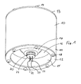
- Fig. 1 shows a schematical perspective general view on the central injection unit 10 from below, having in the embodiment of Fig. 1 a circular cylindrical hollow main body 11.
- Fig. 1 shows the central injection unit 10 during delivery, i.e. in a situation when the lower part of the unit 10 is always sealed by the container holder 40 of Fig. 2 .
- Said body 11 is closed by a lower ring cover 12 and an upper cover 13.
- the embodiment according to Fig. 1 comprises a number of circumferentially arranged screws 14 to close the two covers 12 and 13 on the respective free end of the hollow cylinder body 11.
- the lower cover 12 provides a ring formed rim providing an inner wall 15.
- Said inner wall 15 surrounds a free space, into which the upper portion of the protective container holder 40 according to Fig. 2 can be introduced.
- the body 11 needs not to be cylindrical and can be block-shaped or having a different form. It is important that there is a lower surface 16 as explained below which is provided as an upper closure of the space surrounded by the inner wall 15.
- the horizontal surface 16 is built as a disc with a frustoconical elevation 17.
- an injection cap closure 20 is located which has a lower closing surface 21 comprising of a delivery septum.
- Septum 21 can be of any flexible material allowing to be pierced by hollow needles 22, 23 and 24 allowing for a fluid-tight and gas-tight surface, when the needles 22, 23 and 24 are retracted behind delivery septum 21.
- Needles 22, 23 and 24 are especially needles suitable to deliver small amounts of a fluid and may have any convenient diameter given by a specific application, here usually 0,8 millimeter outer diameter. If in delivery position, the three needles are not positioned at the same length below the septum. As will be show below in connection with the further drawings needles 22 and 24 both have essentially the same lower end position in the delivery mode, whereas needle 23 is shorter or is not provided at all.
- the needles 22, 23 and 24 are oriented parallel one to another and along the main longitudinal axis of the cylinder body 10, in other words perpendicular to the lower surfaces 12, 16 and septum 21.
- the three needles 22, 23 and 24 are positioned according to Fig. 1 . Else they are retracted behind and above the septum 21.
- the injection closure cap 20 may comprise of a crimp cover comprising an inner septum 21 or of a septum holder with thread to be screwed on a complementary thread on the lower surface of the frustoconical elevation 17.
- Septum 21 is shown as lowest surface; usually it is provided as a membrane positioned and held below a rim against a complementary rim surface. Once the needle tips are retracted behind the septum 21, it provides a gas- and liquid-tight interface between a potentially contaminated area and the environment. The main benefit of a septum 21 is therefore shielding the environment from contamination stemming from the needles and is therefore an integral safety component of the system.
- Fig. 2 shows a view, partially as a cross-section, of the lower part of the injection unit 10 with its piston 60 providing the lower surface 16 and the frustoconical extension 17 which extends into a container holder 40.
- Same reference numerals are used throughout all drawings to represent the same or similar features.
- Container holder 40 is preferably a tungsten or lead body if a radioactive fluid is to be delivered. Said cylindrical body has a lower standing surface 41 which surface will be used as interface surface for any delivery and/or dispensing unit of the device.
- the container throughout the following description mentioned as vial 30, is initially positioned inside the container holder 40 in a charging position safely apart from the injection unit 10. Then a drive unit connected below the surface 41 moves the container holder 40 carrying the empty vial 30 to the position shown in Fig. 2 , i.e. below the injection unit 10. Then the container holder 40 is moved up to the cylindrical injection unit 10 to fill the vial 30.
- a protective cover shields the operator from radiation from vial 30 in the container holder 40 during all movements before the shielding lid of the container holder is closed and secured.
- the injection unit 10 may move and the container holder 40 may be fixed. In most applications, however, it is preferred to separate the charging and discharging station from the filling point for safety reasons.
- a drive (not shown in the drawings) which pushes the container holder 40 vertically into position in the injection unit 10.
- a horizontal drive that positions container holder 40 and/or the vial 30 exactly below injection unit 10 and moves it from there back to the (dis)charge position after the filling process is over.
- the container holder 40 comprises an inner wall 42 e.g. defining a cylindrical wall, allowing to create an inner cylindrical space 100 within which the vial 30 can be positioned and transported.
- an inner wall 42 e.g. defining a cylindrical wall, allowing to create an inner cylindrical space 100 within which the vial 30 can be positioned and transported.
- the free room between the outer wall of the vial and the inner wall 42 of the container holder 40 is rather small in volume and the vial 30 stands on the lower surface 43 of this room 100.
- Said surface can be simply flat or can have indentations to fix the vial 30 at a preferred position.
- a typical vial 30 is shown having a neck portion 31 and a crimp cover 32.
- Said crimp cover comprises a vial septum 33.
- Fig. 2 and 3 show a similar crimp cover 20 on the cone 17.
- Crimp cover 20 can be attached on the corresponding neck 25 in analogy to cover 32 on neck 31.
- a threaded cover or any suitable holder may be used to fix septum 21 and/or 33 to its place.
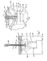
- FIG. 3 shows a detail of Fig. 2 according to the larger circle in Fig. 2.
- Fig. 4 shows a further detail of Fig. 2 according to the smaller circle.
- Figs. 2 to 4 show that space 100 is defined through the cavity created between the frustoconical elevation 17 and the opening space inside container holder 40.
- a seal On the upper end of the container holder 40, i.e. the upper rim 44 there is a seal, here provided by a circular O-ring visualized in Fig. 4 by space 45 which is intended to accommodate a seal ring.
- said upper surface 44 of container holder 40 In the filling position as shown in Fig. 2 said upper surface 44 of container holder 40 is in direct and sealing contact with the lower surface 16 of piston 60.
- Vial septum 33 of vial 30 in the container holder is positioned in a predefined delivery distance from the delivery septum 21.
- the container holder 40 is pushed upwards by a drive preferredly pushing on its upper surface 44 against the surface 16 of the movable 60 which is pushed back against surface 44 by a passive counter force provided by a spring positioned behind the piston 60, thus ensuring a tight seal. More constructional details will be explained below with Fig. 7 and 8 .
- a hydraulic or another active counter force might be used.
- a passive counter force element by a spring improves the safety of the device, as will be seen in connection with the preferred mode of operation of the device according to the invention.
- needles 22 and 24 are extending far enough through the septum 21 of the injection device 10 to pierce also septum 33 of the vial 30 to enter the inner volume 34 of the vial. Therefore, if there is any pressure buildup in a conduit leading to needle 22 then any volume which passes through needle 22 will fill the vial 30 while this liquid will replace the corresponding volume of previous material, usually gas, inside the volume 34 whereas said gas in the vial 30 will be pressure relieved through the second needle 24.
- the conduit attached to the proximal end of needle 24 may be connected to a vacuum pump and any sort of safety equipment - container, disinfection equipment or appropriate filter - to prevent a contamination of the environment by the exhaust of the vial.
- the vial may be flushed by any suitable gas to decontaminate the exhaust line from radioactive gas. Again, the exhaust may be trapped/decontaminated by said methods.
- the third needle 23 is positioned with its lower end 26 in space 100. Septa 21 and 33 are not in contact and said lower end 26 is positioned between the two septa. It penetrates delivery septum 21 but is too short to contact vial septum 33.
- needle connector 122 of needle 22 communicates via vial space 34 with the needle connector 124 of needle 24.
- aliquots of liquid are usually relocated through capillaries by pressurized gas.
- Injection unit 10 and vial 30 therefore need to be protected by a pressure release line.
- Upper end of needle 23 is in direct unilateral contact with space 100. This contact may be used to evacuate/flush said space or alternatively to apply chemical treatment for decontamination (in case of biohazard load).
- Fig. 5 shows the position of the needles 22, 23 and 24 within the injector unit in the moving situation.
- the container holder 40 is still in the same position relative to the septum 21 and piston 60 as in the fill position ( Fig.4 ).
- the only difference is that needles 22, 23 and 24 are retracted and are guided within hollow steel tubes 222, 223 and 224, respectively.
- Steel tubes 222, 223 and 224 are used as needle guides.
- the tubes 222, 223 and 224 as shown in Fig. 9 are fixed in wall 51 and also ensure correct alignment of piston 60.
- the bores in piston 60 are large enough to allow the needle guides to slide easily within.
- the pistion 60, conical extension 17 plus neck 25 are thick enough for the guides to stay within the bores during all movements of the pistion without touching or penetrating septum 21.
- the distance between the piston 60 and the lower container holder 40 is well defined by the contact of the closure surfaces. This allows for a predefined distance between delivery septum 21 and vial septum 33.
- Fig. 5 shows piston 60 as part of the injection unit 10.
- Said piston 60 comprises two circumferential grooves 61 intended to receive O-rings, i.e. sealing rings, to provide an airtight sealed inner space 100. These sealing rings and the intermediate bearing sealing surface are positioned against the inner wall 15 of the injection unit 10.
- Fig. 6 shows a detail view of Fig. 5 .
- Delivery septum 21 and vial septum are in a predefined distance. This allows positioning of needle 23 in the space 100 during the filling and check position, so that the content of space 100 can be checked through this material connection with a suitable detector.
- the third needle can be omitted and a direct checking valve can be provided in piston 60, i.e. allowing a connection between surface 16 and space 100 to check the content for contamination. Then, instead of checking and cleaning space 100 through needle 23, this would be conducted through volume 51 behind piston 60 or by a separate connection to an appropriate tubing.
- the relative position of needles 22, 24 and 23 may be different than shown in the Figures.
- a separate driving unit (as will be shown below in the present case a spring in room 71/72) for needles 22 and 24 and a separate motorized drive to move needle 23 behind delivery septum 21 may be installed.
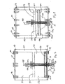
- Fig. 7 shows the injection unit 10 of Fig. 1 in a partial cross-section view in a non-filling position.
- Fig. 8 shows the injection unit 10 of Fig. 1 in the same partial cross-section view but in a filling position.
- Fig. 7 shows the upper closure 13, being a cover plate screwed to the wall of body 11.
- a seal for example a silicon flat gasket 59, provides for a sealing element against the environment.
- Within the body 11 is provided a horizontal supporting wall 51.
- piston 60 is provided inside hollow space 51.
- Piston 60 preferably comprises two circumferential grooves 61 to accommodate sealing rings.
- the lower plate 12 secures the piston 60 against the force of the compression spring as explained in the following paragraphs.
- cover plate 13 and cover ring 12 are fixed by easily accessible screws: a) Top side, cover plate 13: Inside, the geometry/length of virtually any commercially available needle 22, 23 and 24 can be adjusted easily to any commercially available vial 30, for example: standard luer needles are pushed into the needle guide. The needle can then be fixed in position at correct penetration depth by a simple screw (not visible in the figures). This technical detail helps to be independent of specific suppliers and ensure flexibility for future requirements (i.e. specific vials, specific needle materials) as all components that are in direct contact with the liquid to be dispensed can be easily and cheaply replaced. b) Bottom side: The piston seals 61 will have to be replaced from time to time and ring 12 then can to be removed by a simple mechanical action.
- the inner supporting wall 51 separates the inside volume 52 of the body 11 into two parts which have received the same reference numeral 52 since they are connected through a bore 53 within the supporting wall 51.
- Piston 60 is adapted to move perpendicular to supporting wall 51. Piston 60 comprises the lower surface 16 as well as the central frustoconical extension 17.
- the lower inside space 52 between the supporting wall 51 and piston 60 houses a compression spring (not shown in the drawings), extending directly or indirectly against piston 60 from above.
- room 72 in Fig.7 provides the space for the semi relaxed compression spring inside and room 71 in Fig. 8 provides for the space of the compressed spring.
- an extension spring or any other means providing a storage of potential energy preferably a conservative storage means, which has no active drives.
- a simple energy storage means can comprise a hydraulic connection of the piston with a fluid reservoir lifting subsequently a sequence of weights.
- Fig. 9 shows a perspective view into the central injection unit like Fig. 1 from below, but with piston 60 removed.
- the drawing provides a clear view onto the intermediate wall 51.
- Lower rim 54 of the body 11 is not covered by lower rim cover 12. Therefore, threaded bores 114 are visible, receiving screws 14 as shown above.
- screws 14 it is possible to replace in the various embodiments screws 14 by rivets, or lower rim cover 12 can be clamped on surface 54. It is an advantage to be able to retrieve piston 60 to replace sealing rings and to access the spring room above it.
- guiding tubes 222, 223 and 224 are fixed. Tubes 222, 223 and 224 receive the needles 22, 23 and 24 extending beyond the tubes as shown in Fig. 9 .
- Two mounting holes 55 are shown, usually provided to attach tubes 222, 223 and 224 within respective bores for these tubes in wall 51. It is noted that the stiff and rigid steel tubes 222, 223 and 224, oriented parallel one to another and oriented perpendicular to wall 51 and piston 60 provide an additional guiding surface for piston 60, since the free ends of the tubes are preferably mounted in corresponding guiding holes in piston 60 with the proviso that the free needle tips can extend below the frustoconical extension 17 to cross septum 21.
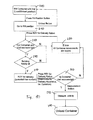
- Fig. 10 shows a flow chart of the general process executed for charging a vial with an embodiment of the invention according to Fig. 1 to 9 ; and Fig. 11 shows a flowchart for the movement interlock handling. They are used to explain the method of use of a system having an apparatus according to the invention.
- the initial position shows the container holder 40 in a loading station, where it receives - in a loading step 200 - the empty vial 30.
- regulatory bodies usually require the container holder 40 to be covered by a shielding lid, closing the space 100 towards the upper space and protecting personnel.
- a drive moves the container holder towards the fill position in a charging step 210 after pressing a fill position button. During this displacement the optional shielding lid is removed and intermittently stored. Pushing the unload button allows to revert the movement towards the starting position.
- the vacuum check step is conducted.
- the needle 23 is attached to a vacuum pump and the applied suction empties the space 100 of the gas it contains. Since the volume 34 of vial 30 is not connected, only the space 100 is emptied during vacuum check step 220. There are two possible results: Either the intended vacuum level is reached, and then the container holder space 100 is sealed air-tight against the environment. Or the closing is not perfect. If not then an error signal is issued and an error mode 230 is entered and all container movements are locked. It is then possible to retract the container holder 40 following specific emergency rules. If the vial would be broken at that stage, then there would be a connection with the vial space 34 and thus via the needles 22 and 24 until relevant valves.
- Radioactive traces could be detected by a contamination meter or the (unusual) decreasing of the vacuum at needle 23 or the increasing (unusual) vacuum in the branches of needles 22 and 24 could be detected by a separate pressure gauge. Needle 23 can also be used as disinfection needle and introduce a disinfectant into space 100.
- the building safety check step 240 is executed.
- This building safety comprises the decision, if the delivery can be requested. This includes for example, that room ventilation is ok, that exhaust filters (if needed) are present, that authorization for the use of the dispensing unit has been given, that waste containers are ready if radioactive gases have to be pumped off, or any other process the customer or regulatory bodies acknowledge appropriate to ensure safe and proper use.
- the "ok" interlock-signal by building safety is usually given by a potential free contact.
- box 250 is ready and an interlock (best engineered as a potential free contact, i.e. a relay) is asserted to signal to the sending machine "ready for delivery".
- the sending apparatus is provided with an additional interlock input (potential free contact) which blocks the moving unit and therefore locks the container safely in its position until the sending apparatus unlocks the moving unit again after the delivery process is over. This prevents any putative handling or hardware error to result in a hazardous situation.
- Step 250 comprises the delivery action, i.e. actuating the sending apparatus, e.g. a cyclotron, for deliverance of the radioactive fluid. This fluid is brought through a conduit into the needle 22 and guided into the container.
- Fluid measurements are made upstream of the apparatus or the displaced gas volume can be checked which leaves through needle 24. During this time the vacuum or under-pressure in space 100 through needle 23 is preferably maintained. Delivery usually happens through vial-fill and vent-valves being opened electronically bringing needles 22, 24 and vial space 34 into the circuit of the filling apparatus.
- a delivery check step 260 is conducted. This comprises of checking the radioactivity through the evacuated gas through needle 23, which would identify a breaking of the vial 34 or any other leakage problem, e.g. of septum 33. If not, than the error mode 230 is asserted.
- space 100 is evacuated via needle 23 to a very low pressure and the vacuum valve is then closed and pressure monitored by a pressure gauge. Any spilled liquid with an appreciable vapor pressure, a contamination hazard, would then evaporate and the pressure in the space would immediately rise and indicate contamination of space 100 by a liquid. If contamination of space 100 is found or assumed, the space can be thoroughly decontaminated by continuous evacuation.
- the container holder 40 and the space 100 is flushed with air or an inert gas before the container holder 40 is lowered through activation of the corresponding drive.
- Compression spring pushes back the piston 60 inside the cylinder 11 and starts to relax. Piston slides further downwards and presses the vial downwards of the needles 22 and 24. The piston 60 slides over the vial-fill- and vial-vent-needles 22 and 24 and the vacuum/decontamination needle 23 and brings them back behind the delivery septum 21.
- the vial 30 falls back into the container holder 40 and the needles 22, 23, 24 or any additional needle for venting/disinfecting/decontamination, which may be provided as a fourth or fifth needle, will be sealed inside of the cylinder space from the container. At that point the seal between piston 60 and container holder 40 is still intact and space 100 isolated from the environment. Container holder 40 exits the lower rim 12 and only now the seal between piston 60 and container holder 40 is broken. Now piston 60 is sealing the needles and the inside of cylinder 11 against the environment, i.e. a seal in the other direction.
- the body 10 comprises a lower outer rim wall 11, 15 extending beyond the body closure surface, provide by wall 16 and piston 60, wherein the corresponding container holder 40 has an outer circumference allowing entering the inner space of the body 10 created by the lower outer rim wall.
- the container holder 40 is moved back to the loading, here unloading position in an unloading step.
- An additional measurement of e.g. radioactivity of the vial 30 can be performed before replacing the intermittently stored cover and bringing the container holder back to the starting position.
- Measurements of the system integrates the radioactivity and gives feedback to the user for values above a defined threshold, signaling a problem with the delivery, the cause for which could e.g. be a broken vial. If, for whatever reason, a contamination occurs, it is automatically removed by the system, e.g. through needle 23, blocking the respective delivery unit until the decontamination is complete. Even when a delivery fails, the system continues working normally after automatic decontamination. While manual delivery requires a test wiping at the end, this step is obviated by the automated monitoring as it yields information about residual activity in the system.
- Fig. 11 shows the movement steps of the active drive for the single displacements as loading, unloading, filling or measurement, upon giving the order in an order step 300.
- the electronic unit initially checks, if the container (holder) 40 is present at that place in a position check step 310. If not, there is no operation 330. If yes and if there is no other error pending 320 and the safety check 340 is positive, then the delivery check step is conducted. This relates to the fact that no displacement of the container holder in whatever direction has to be allowed during delivery. Therefore the answer on a movement order 300 during delivery is assertion of an error relay 360. Otherwise the movement 370 is executed.
Landscapes
- Engineering & Computer Science (AREA)
- Mechanical Engineering (AREA)
- Medical Preparation Storing Or Oral Administration Devices (AREA)
Abstract
An apparatus for dispensing a hazardous fluid into a container (30) comprises a body within which at least two hollow needles (22, 24) are positioned above a delivery septum (21). A container holder (40) receives a container (30) within an inner space (100), wherein during and for delivery of such a fluid into the container (30) the distal portions of the needles (22, 24) are adapted to be advanced across the delivery septum (21) and across the container septum (33) of the container (30). The container holder (40) and a piston (60) as a complementary closure surface of the body are moved together by a driving means until said closure surfaces meet, turning the inner space (100) accommodating the container (30) into a sealed space. A further relative movement of the needles (22, 24) against the container holder (40) allows the distal portions of the needles (22, 24) to first cross the delivery septum (21) and subsequently cross the container septum (33), both only after the creation of the sealed inner space (100). This effectively reduces the volume of the hot cell (100) and allows the check and evacuation of this space through a third conduit (23).
Description
- The present invention relates to an apparatus for dispensing a hazardous fluid into a container, especially a vial closed with a septum, with the features of the preamble of
claim 1. Furthermore a method for dispensing such hazardous fluids is disclosed as well as a delivering system comprising said apparatus. - The prior art comprises a number of solutions to dispense a fluid, especially a biohazardous or radioactive fluid into a container. The dispensing operation is usually conducted within a protected enclosure, usually made of concrete or of lead in a steel frame as usual in radiopharmacy, having shielded windows and manipulators operated by remote control, used to handle these hazardous especially biologically dangerous or radioactive materials. Such a protected enclosure is named hot cell, especially within the technologies of dispensing radioactive materials but will be used within this specification in the same way for handling bio-hazards.
-
US 2010/218846 provides a method and apparatus for a contamination-free transfer of a hazardous liquid from one container to another. The aim of this teaching is to avoid any leakage of the liquid or air contaminated by the liquid or vapors of the liquid to the surrounding volume wherein the needles are located within a housing, crossing a first septum and being adapted to pierce a second septum, provided in a predefined distance from the first septum of the device. When the piercing of said second septum occurs, said second septum is in contact with a third septum being part of a vial adaptor, which is attached to the vial which has to receive the hazardous fluid. -
TW 440 879B -
KR 100 677 664B -
EP 1 860 665 Al -
US 4,659,925 provides a high pressure radioisotope injection system. This material is provided within a vial in a shipping container. The vial is pierced by two needles as fluid carrying lines and the radioactive material is then transferred via one needle to a previously evacuated pressure flask. The needles are surrounded by a cylindrical extension which ensures, that the needles will be correctly oriented and effectively pierce the septum of the vial. The lower protection block is connected to a support which houses the needles. - The prior art usually suggests a transfer of these liquids in high volume hot cells which have then to be evacuated and in the case of an incident they are to be thoroughly cleaned.
US 2010/218846 proposes a reduction of the volume through a complicated system necessitating the use of a vial adaptor and a complex mechanism, which is not easily positioned, used and cleaned. - At present, there are no commercially available systems for the automated delivery of radionuclides from liquid targets or modules. The same applies for the transfer of biohazardous materials. Conventional methods in, for example, the delivery of 18F generally involve a manual handling step conducted in a full-sized hot-cell. Typically this hands-on step requires approximately 15 minutes completing with reduced specific activity of the product, increased radiation exposure, and a high potential for contamination.
- Based on the prior art, the present invention has the object to standardize radionuclide delivery, minimize the footprint, decrease the time for delivery, and improve radiation safety by developing an automated system, especially a delivery system, which uses standard lead or tungsten containers for radioactive materials. It is then a further advantage that these standard containers can directly be used for shipping.
- Said object and further advantages are reached with the apparatus according to any one of the attached claims. Furthermore an apparatus is suggested including the delivery system.
- An apparatus for dispensing a hazardous fluid into a container, especially a vial closed with a container septum, according to the invention comprises a body within which at least two hollow needles are positioned above a delivery septum. It further comprises a container holder adapted to receive a container within an inner space. During and for delivery of such a fluid into the container the distal portions of the needles, i.e. the tips and the adjacent shaft portion of the needles, are adapted to be advanced across the delivery septum and across the container septum of a container positioned in the container holder. The container holder comprises a closure surface and the body comprises a complementary closure surface, which can be moved into sealing contact. The apparatus comprises a driving means, which can be a motor or a hand driven displacement unit, adapted to provide a relative movement of the container holder against the body until the closure surfaces meet turning the inner space holding the container into a sealed space. A second additional relative movement of the needles against the container holder allows the distal portions of the needles to first cross the delivery septum and subsequently cross the container septum only after the creation of the sealed inner space by the first movement.
- In this respect it is important to create said airtight and fluid tight space. This relative movement can be combined through providing the closure surface of the body by a piston adapted to be displaced by the complementary closure surface of the container holder against a conservative counter force. Such a force can especially be the force of a spring provided in the body pretensioning the piston.
- The container holder and a piston as a complementary closure surface of the body are caused to approach by a driving means until said closure surfaces contact, turning the inner space of the container into a sealed space. A further relative movement of two needles against the container holder allows the distal portions of the needles to first cross the delivery septum and subsequently cross the container septum, both only after the creation of the sealed inner space. This effectively reduces the volume of the hot cell and allows for decontamination and evacuation of this space through a third conduit after a suitable check.
- In a further advantageous embodiment the needles are fixedly positioned inside body above the delivery septum in the non-filling position of the piston. if the container holder is moved upwards against the body the delivery septum and the container septum of a container are pierced by at least two needles. The driving means and the driving unit providing the two relative movements are combined into one single drive by a counterforce by a spring that presses the piston on the container holder thereby effectively controlling the relative movement of the fixed needles in versus the delivery septum.
- The system according to the invention has the advantage that it is designed as a self-contained unit constructed from a minimum number of components. In fact, there are four parts including a rigid support, two actuators for a precise control over horizontal and vertical movement, preferably having a precision higher than 0.05 millimeter, a shielding container, usually lead or tungsten, in the case of delivery of radioactive fluids, and a delivery system according to an embodiment of the invention.
- The entire unit of a first embodiment has 1000 millimeter in length, 400 millimeter width and approximately 600 millimeter high. The delivery system according to this embodiment can accommodate standard 3 - 10 milliliter penicillin vials but can be easily customized to hold all common vials and sizes of lead/tungsten containers. The unit operates on a 110/230 V AC power socket. To keep the costs low this unit uses standard industrial materials. It is clear that the room requirements, especially in length and width can even be significantly reduced, e.g. by 50 percent each, thus allowing for a small sized secure environment which can be easily maintained, dismounted and cleaned.
- The automated process using the system according to the embodiment reduced the time required between end of bombardment of the material and a shipment ready product to less than 5 minutes by combination of previously separate steps of delivery and contamination testing into one. Decontamination was also automated and, as the unit requires no user intervention, radiation exposure was reduced. The footprint of the whole unit is 10 times smaller than a conventional hot-cell as a comparative example.
- During the delivery process using the presented system according to an embodiment of the invention, the commercial shielding container and the delivery system form a liquid/gas tight entity. It is easy to check this volume for contaminations and, if necessary, also easy to decontaminate.
- The volume of the delivery system was minimized and is dependent mainly on the size of the vial containers. Compared to a standard research hot cell the size of the delivery system, including shielding and wiring, was reduced by a factor of ten. Due to the easy construction and the abdication of not necessary electronics the control cabinet was reduced from more then 300 clamps to less then 50.
- Key benefits of the system are: 10 times smaller than an average hot cell; 5 times less electrical clamps; faster delivery of isotopes; less radiation exposure for user; lower production cost; small number of and easily exchangeable commercial parts leading to low maintenance cost, both with respect to labor cost and consumables cost; portable system due to its size; and finally easily adaption to a custom production site.
- During the delivery process the shielding container and the delivery system form a liquid/gas tight entity. It is easy to check this volume for contaminations and if it is necessary also easy to decontaminate.
- If the body closure surface comprises a downward extension that houses the delivery septum, the free inner volume space of the hot cell can be further reduced, it creates a better seal during displacement of the container holder inside the inner wall of the body and the needles are protected more easily behind the delivery septum.
- Further embodiments of the invention are laid down in the dependent claims.
- A septum in the context of the present technology is a dividing membrane between two cavities in a mechanical device, intended to be pierced by hollow needles to deliver fluids from one side of the cavity into the other, here a vial or container. After the advancing of the needles to effect the delivery and the following retracting movement of the needles the septum is and remains fluid tight and essentially gas tight.
- Preferred embodiments of the invention are described in the following with reference to the drawings, which are for the purpose of illustrating the present preferred embodiments of the invention and not for the purpose of limiting the same. In the drawings,
- Fig. 1
- shows a perspective general view from below on the central injection unit according to an embodiment of the apparatus;
- Fig. 2
- shows a part cross-section of a container holder of the apparatus and the lower part of the central injection unit according to
Fig. 1 ; - Fig. 3
- shows a first detail view of
Fig. 2 ; - Fig. 4
- shows a second detail view of
Fig. 2 ; - Fig. 5
- shows the position of the needles within the injector unit in the moving situation;
- Fig. 6
- shows a detail view of
Fig. 5 ; - Fig. 7
- shows the injection unit of
Fig. 1 in a partial cross-section view in a non-filling position; - Fig. 8
- shows the injection unit of
Fig. 1 in a partial cross-section view in a filling position; - Fig. 9
- shows a perspective view on the central injection unit according to
Fig. 1 from below with the piston removed; - Fig. 10
- shows a flow chart of the general process executed for charging a vial with
- Fig. 11
- an embodiment of the invention according to
Fig. 1 to 8 ; and shows a flowchart for the movement interlock handling. -
Fig. 1 shows a schematical perspective general view on thecentral injection unit 10 from below, having in the embodiment ofFig. 1 a circular cylindrical hollowmain body 11.Fig. 1 shows thecentral injection unit 10 during delivery, i.e. in a situation when the lower part of theunit 10 is always sealed by thecontainer holder 40 ofFig. 2 . -
Said body 11 is closed by alower ring cover 12 and anupper cover 13. The embodiment according toFig. 1 comprises a number of circumferentially arrangedscrews 14 to close the two covers 12 and 13 on the respective free end of thehollow cylinder body 11. Thelower cover 12 provides a ring formed rim providing aninner wall 15. Saidinner wall 15 surrounds a free space, into which the upper portion of theprotective container holder 40 according toFig. 2 can be introduced. Of course thebody 11 needs not to be cylindrical and can be block-shaped or having a different form. It is important that there is alower surface 16 as explained below which is provided as an upper closure of the space surrounded by theinner wall 15. - Inside the
inner wall 15 is provided a circular usually horizontallower surface 16 of thebody 11. Saidsurface 16 can be displaced perpendicular to its orientation, i.e. in the direction of the longitudinal axis of thecylindrical body 11 as will be explained below. Thehorizontal surface 16 is built as a disc with afrustoconical elevation 17. At its center aninjection cap closure 20 is located which has alower closing surface 21 comprising of a delivery septum.Septum 21 can be of any flexible material allowing to be pierced byhollow needles needles delivery septum 21.Needles needle 23 is shorter or is not provided at all. - Preferably the
needles cylinder body 10, in other words perpendicular to thelower surfaces septum 21. - If one of the needles delivers a fluid into the container or
vial 30, the threeneedles Fig. 1 . Else they are retracted behind and above theseptum 21. - The
injection closure cap 20 may comprise of a crimp cover comprising aninner septum 21 or of a septum holder with thread to be screwed on a complementary thread on the lower surface of thefrustoconical elevation 17.Septum 21 is shown as lowest surface; usually it is provided as a membrane positioned and held below a rim against a complementary rim surface. Once the needle tips are retracted behind theseptum 21, it provides a gas- and liquid-tight interface between a potentially contaminated area and the environment. The main benefit of aseptum 21 is therefore shielding the environment from contamination stemming from the needles and is therefore an integral safety component of the system. -
Fig. 2 shows a view, partially as a cross-section, of the lower part of theinjection unit 10 with itspiston 60 providing thelower surface 16 and thefrustoconical extension 17 which extends into acontainer holder 40. Same reference numerals are used throughout all drawings to represent the same or similar features. -
Container holder 40 is preferably a tungsten or lead body if a radioactive fluid is to be delivered. Said cylindrical body has a lower standing surface 41 which surface will be used as interface surface for any delivery and/or dispensing unit of the device. In other words, the container, throughout the following description mentioned asvial 30, is initially positioned inside thecontainer holder 40 in a charging position safely apart from theinjection unit 10. Then a drive unit connected below the surface 41 moves thecontainer holder 40 carrying theempty vial 30 to the position shown inFig. 2 , i.e. below theinjection unit 10. Then thecontainer holder 40 is moved up to thecylindrical injection unit 10 to fill thevial 30. In a first step after the central filling operation the container holder is lowered belowinjection unit 10 and then, in a second step, moved sideways to the (dis)charging position where vial 30 (in case of a biohazard load) or thewhole container holder 40 including vial 30 (in case of a radioactive load) can be removed from the system. In the case of a radioactive load, a protective cover shields the operator from radiation fromvial 30 in thecontainer holder 40 during all movements before the shielding lid of the container holder is closed and secured. - Alternatively, the
injection unit 10 may move and thecontainer holder 40 may be fixed. In most applications, however, it is preferred to separate the charging and discharging station from the filling point for safety reasons. - Preferably there is a drive (not shown in the drawings) which pushes the
container holder 40 vertically into position in theinjection unit 10. Likewise is convenient to have a horizontal drive that positionscontainer holder 40 and/or thevial 30 exactly belowinjection unit 10 and moves it from there back to the (dis)charge position after the filling process is over. - The above mentioned drive is initially only related to said relative movement which not necessarily comprises the movement of the needles through the
septum 21. Different solutions for this second relative movement are now explained below. - The
container holder 40 comprises aninner wall 42 e.g. defining a cylindrical wall, allowing to create an innercylindrical space 100 within which thevial 30 can be positioned and transported. Preferably the free room between the outer wall of the vial and theinner wall 42 of thecontainer holder 40 is rather small in volume and thevial 30 stands on thelower surface 43 of thisroom 100. Said surface can be simply flat or can have indentations to fix thevial 30 at a preferred position. - In the figures according to an embodiment of the invention a
typical vial 30 is shown having a neck portion 31 and acrimp cover 32. Said crimp cover comprises a vial septum 33.Fig. 2 and 3 show asimilar crimp cover 20 on thecone 17. Crimpcover 20 can be attached on the corresponding neck 25 in analogy to cover 32 on neck 31. Alternatively a threaded cover or any suitable holder may be used to fixseptum 21 and/or 33 to its place. -
Fig. 3 shows a detail ofFig. 2 according to the larger circle inFig. 2. Fig. 4 shows a further detail ofFig. 2 according to the smaller circle. -
Figs. 2 to 4 show thatspace 100 is defined through the cavity created between thefrustoconical elevation 17 and the opening space insidecontainer holder 40. On the upper end of thecontainer holder 40, i.e. the upper rim 44 there is a seal, here provided by a circular O-ring visualized inFig. 4 byspace 45 which is intended to accommodate a seal ring. In the filling position as shown inFig. 2 said upper surface 44 ofcontainer holder 40 is in direct and sealing contact with thelower surface 16 ofpiston 60. - Vial septum 33 of
vial 30 in the container holder is positioned in a predefined delivery distance from thedelivery septum 21. - The
container holder 40 is pushed upwards by a drive preferredly pushing on its upper surface 44 against thesurface 16 of the movable 60 which is pushed back against surface 44 by a passive counter force provided by a spring positioned behind thepiston 60, thus ensuring a tight seal. More constructional details will be explained below withFig. 7 and 8 . Alternatively, a hydraulic or another active counter force might be used. However, a passive counter force element by a spring improves the safety of the device, as will be seen in connection with the preferred mode of operation of the device according to the invention. - As shown in
Figs. 2 and 3 , needles 22 and 24 are extending far enough through theseptum 21 of theinjection device 10 to pierce also septum 33 of thevial 30 to enter theinner volume 34 of the vial. Therefore, if there is any pressure buildup in a conduit leading toneedle 22 then any volume which passes throughneedle 22 will fill thevial 30 while this liquid will replace the corresponding volume of previous material, usually gas, inside thevolume 34 whereas said gas in thevial 30 will be pressure relieved through thesecond needle 24. The conduit attached to the proximal end ofneedle 24 may be connected to a vacuum pump and any sort of safety equipment - container, disinfection equipment or appropriate filter - to prevent a contamination of the environment by the exhaust of the vial. Alternatively the vial may be flushed by any suitable gas to decontaminate the exhaust line from radioactive gas. Again, the exhaust may be trapped/decontaminated by said methods. - If the
container holder 40 is in filling position thethird needle 23 is positioned with itslower end 26 inspace 100.Septa 21 and 33 are not in contact and saidlower end 26 is positioned between the two septa. It penetratesdelivery septum 21 but is too short to contact vial septum 33. - Therefore, needle connector 122 of
needle 22 communicates viavial space 34 with theneedle connector 124 ofneedle 24. In case of dispensing radioactive solution, aliquots of liquid are usually relocated through capillaries by pressurized gas.Injection unit 10 andvial 30 therefore need to be protected by a pressure release line. Upper end ofneedle 23 is in direct unilateral contact withspace 100. This contact may be used to evacuate/flush said space or alternatively to apply chemical treatment for decontamination (in case of biohazard load). -
Fig. 5 shows the position of theneedles container holder 40 is still in the same position relative to theseptum 21 andpiston 60 as in the fill position (Fig.4 ). The only difference is that needles 22, 23 and 24 are retracted and are guided withinhollow steel tubes Steel tubes tubes Fig. 9 are fixed inwall 51 and also ensure correct alignment ofpiston 60. The bores inpiston 60 are large enough to allow the needle guides to slide easily within. Importantly thepistion 60,conical extension 17 plus neck 25 are thick enough for the guides to stay within the bores during all movements of the pistion without touching or penetratingseptum 21. The distance between thepiston 60 and thelower container holder 40 is well defined by the contact of the closure surfaces. This allows for a predefined distance betweendelivery septum 21 and vial septum 33. -
Fig. 5 showspiston 60 as part of theinjection unit 10. Saidpiston 60 comprises twocircumferential grooves 61 intended to receive O-rings, i.e. sealing rings, to provide an airtight sealedinner space 100. These sealing rings and the intermediate bearing sealing surface are positioned against theinner wall 15 of theinjection unit 10. -
Fig. 6 shows a detail view ofFig. 5 .Delivery septum 21 and vial septum are in a predefined distance. This allows positioning ofneedle 23 in thespace 100 during the filling and check position, so that the content ofspace 100 can be checked through this material connection with a suitable detector. In an embodiment not shown in the drawings, the third needle can be omitted and a direct checking valve can be provided inpiston 60, i.e. allowing a connection betweensurface 16 andspace 100 to check the content for contamination. Then, instead of checking and cleaningspace 100 throughneedle 23, this would be conducted throughvolume 51 behindpiston 60 or by a separate connection to an appropriate tubing. - In principle, for requirements not discussed here, the relative position of
needles room 71/72) forneedles needle 23 behinddelivery septum 21 may be installed. -
Fig. 7 shows theinjection unit 10 ofFig. 1 in a partial cross-section view in a non-filling position.Fig. 8 shows theinjection unit 10 ofFig. 1 in the same partial cross-section view but in a filling position. -
Fig. 7 shows theupper closure 13, being a cover plate screwed to the wall ofbody 11. A seal, for example a silicon flat gasket 59, provides for a sealing element against the environment. Within thebody 11 is provided a horizontal supportingwall 51. At the lower end of thebody 11piston 60 is provided insidehollow space 51.Piston 60 preferably comprises twocircumferential grooves 61 to accommodate sealing rings. Thelower plate 12 secures thepiston 60 against the force of the compression spring as explained in the following paragraphs. It is essential to have easy access to the interior of the delivery system for optimized maintenance, so both coverplate 13 andcover ring 12 are fixed by easily accessible screws: a) Top side, cover plate 13: Inside, the geometry/length of virtually any commerciallyavailable needle available vial 30, for example: standard luer needles are pushed into the needle guide. The needle can then be fixed in position at correct penetration depth by a simple screw (not visible in the figures). This technical detail helps to be independent of specific suppliers and ensure flexibility for future requirements (i.e. specific vials, specific needle materials) as all components that are in direct contact with the liquid to be dispensed can be easily and cheaply replaced. b) Bottom side: The piston seals 61 will have to be replaced from time to time andring 12 then can to be removed by a simple mechanical action. - The inner supporting
wall 51 separates theinside volume 52 of thebody 11 into two parts which have received thesame reference numeral 52 since they are connected through a bore 53 within the supportingwall 51.Piston 60 is adapted to move perpendicular to supportingwall 51.Piston 60 comprises thelower surface 16 as well as the centralfrustoconical extension 17. The lower insidespace 52 between the supportingwall 51 andpiston 60 houses a compression spring (not shown in the drawings), extending directly or indirectly againstpiston 60 from above. It can be positioned against supportingwall 51 but its upper end can also be lodged in a holder ofouter wall 11, since it is only important that it provides a pretension ontopiston 60 so that piston is always in a well-defined lower position and that it provides an increasing counter force, when thecontainer holder 40 is pushed upwards relative tobody 11, so that the airtight sealing ofspace 100 occurs. - Therefore
room 72 inFig.7 provides the space for the semi relaxed compression spring inside androom 71 inFig. 8 provides for the space of the compressed spring. Of course it is also possible to use an extension spring or any other means providing a storage of potential energy, preferably a conservative storage means, which has no active drives. A simple energy storage means can comprise a hydraulic connection of the piston with a fluid reservoir lifting subsequently a sequence of weights. - It can be clearly seen from the comparison between
Fig. 7 and 8 that - in the embodiment shown -needles unit 10 as a whole. The retraction ofpiston 60 insidebody 11 movesdelivery septum 21 so that all threeneedles frustoconical extension 17. In the disposition ofFig. 8 theneedles space 34 ofvial 30 whereinneedle 23 provides the material contact tospace 100; wherein both circuits of conduits are completely separated. -
Fig. 9 shows a perspective view into the central injection unit likeFig. 1 from below, but withpiston 60 removed. The drawing provides a clear view onto theintermediate wall 51. Lower rim 54 of thebody 11 is not covered bylower rim cover 12. Therefore, threadedbores 114 are visible, receivingscrews 14 as shown above. Of course, it is possible to replace in the various embodiments screws 14 by rivets, orlower rim cover 12 can be clamped on surface 54. It is an advantage to be able to retrievepiston 60 to replace sealing rings and to access the spring room above it. Atinside wall 51 guidingtubes Tubes needles Fig. 9 . Two mountingholes 55 are shown, usually provided to attachtubes wall 51. It is noted that the stiff andrigid steel tubes piston 60 provide an additional guiding surface forpiston 60, since the free ends of the tubes are preferably mounted in corresponding guiding holes inpiston 60 with the proviso that the free needle tips can extend below thefrustoconical extension 17 to crossseptum 21. -
Fig. 10 shows a flow chart of the general process executed for charging a vial with an embodiment of the invention according toFig. 1 to 9 ; andFig. 11 shows a flowchart for the movement interlock handling. They are used to explain the method of use of a system having an apparatus according to the invention. - As mentioned above, the initial position shows the
container holder 40 in a loading station, where it receives - in a loading step 200 - theempty vial 30. In case of a radioactive liquid to be delivered, regulatory bodies usually require thecontainer holder 40 to be covered by a shielding lid, closing thespace 100 towards the upper space and protecting personnel. A drive moves the container holder towards the fill position in a charging step 210 after pressing a fill position button. During this displacement the optional shielding lid is removed and intermittently stored. Pushing the unload button allows to revert the movement towards the starting position. - Reaching the fill position implies pushing the
container holder 40 against the force of the spring against thepiston 60 to create the airtight seal at sealingring place 45. Initially, when thecontainer holder 40 is below thepiston 60, then thepiston 60 seals the inside of the cylinder and the needles against the environment. Starting from the point in time when the containerholder contacts piston 60, thepiston 60 seals the inside of the cylinder from thecontainer holder 40. During this relative displacement ofcontainer holder 40 againstinjection unit body 11, the stationary needle tips are nevertheless pushed against and through thedelivery septum 21, and for theneedles Piston 60 acts as a cover and the sealing is improved by the sealing rings ingrooves 61. - Then the vacuum check step is conducted. The
needle 23 is attached to a vacuum pump and the applied suction empties thespace 100 of the gas it contains. Since thevolume 34 ofvial 30 is not connected, only thespace 100 is emptied duringvacuum check step 220. There are two possible results: Either the intended vacuum level is reached, and then thecontainer holder space 100 is sealed air-tight against the environment. Or the closing is not perfect. If not then an error signal is issued and anerror mode 230 is entered and all container movements are locked. It is then possible to retract thecontainer holder 40 following specific emergency rules. If the vial would be broken at that stage, then there would be a connection with thevial space 34 and thus via theneedles needle 23 or the increasing (unusual) vacuum in the branches ofneedles Needle 23 can also be used as disinfection needle and introduce a disinfectant intospace 100. - If the vacuum check 220 was answered affirmatively, i.e. "Y" in
Fig. 10 for yes and not "N" for no, then the buildingsafety check step 240 is executed. This building safety comprises the decision, if the delivery can be requested. This includes for example, that room ventilation is ok, that exhaust filters (if needed) are present, that authorization for the use of the dispensing unit has been given, that waste containers are ready if radioactive gases have to be pumped off, or any other process the customer or regulatory bodies acknowledge appropriate to ensure safe and proper use. The "ok" interlock-signal by building safety is usually given by a potential free contact. - If all safety checks are processed satisfactorily,
box 250 is ready and an interlock (best engineered as a potential free contact, i.e. a relay) is asserted to signal to the sending machine "ready for delivery". The sending apparatus is provided with an additional interlock input (potential free contact) which blocks the moving unit and therefore locks the container safely in its position until the sending apparatus unlocks the moving unit again after the delivery process is over. This prevents any putative handling or hardware error to result in a hazardous situation. Step 250 comprises the delivery action, i.e. actuating the sending apparatus, e.g. a cyclotron, for deliverance of the radioactive fluid. This fluid is brought through a conduit into theneedle 22 and guided into the container. Fluid measurements are made upstream of the apparatus or the displaced gas volume can be checked which leaves throughneedle 24. During this time the vacuum or under-pressure inspace 100 throughneedle 23 is preferably maintained. Delivery usually happens through vial-fill and vent-valves being opened electronically bringingneedles vial space 34 into the circuit of the filling apparatus. - After filling a
delivery check step 260 is conducted. This comprises of checking the radioactivity through the evacuated gas throughneedle 23, which would identify a breaking of thevial 34 or any other leakage problem, e.g. of septum 33. If not, than theerror mode 230 is asserted. Alternatively,space 100 is evacuated vianeedle 23 to a very low pressure and the vacuum valve is then closed and pressure monitored by a pressure gauge. Any spilled liquid with an appreciable vapor pressure, a contamination hazard, would then evaporate and the pressure in the space would immediately rise and indicate contamination ofspace 100 by a liquid. If contamination ofspace 100 is found or assumed, the space can be thoroughly decontaminated by continuous evacuation. If evaporation of contaminant is not possible at a large underpressure it poses no or no appreciable danger at ambient pressure and the container may be released/discharged for further appropriate action. The apparatus itself, however, is ready for further use. Such a process is easiest carried out if (a) container and apparatus, the hot cell, are very vacuum tight and (b) if the volume of the hot cell is small enough. - If the
security check 260 is passed, "Y", then thecontainer holder 40 and thespace 100 is flushed with air or an inert gas before thecontainer holder 40 is lowered through activation of the corresponding drive. Compression spring pushes back thepiston 60 inside thecylinder 11 and starts to relax. Piston slides further downwards and presses the vial downwards of theneedles piston 60 slides over the vial-fill- and vial-vent-needles decontamination needle 23 and brings them back behind thedelivery septum 21. Thevial 30 falls back into thecontainer holder 40 and theneedles piston 60 andcontainer holder 40 is still intact andspace 100 isolated from the environment.Container holder 40 exits thelower rim 12 and only now the seal betweenpiston 60 andcontainer holder 40 is broken. Nowpiston 60 is sealing the needles and the inside ofcylinder 11 against the environment, i.e. a seal in the other direction. This is possible since thebody 10 comprises a lowerouter rim wall wall 16 andpiston 60, wherein the correspondingcontainer holder 40 has an outer circumference allowing entering the inner space of thebody 10 created by the lower outer rim wall. - Then the
container holder 40 is moved back to the loading, here unloading position in an unloading step. An additional measurement of e.g. radioactivity of thevial 30 can be performed before replacing the intermittently stored cover and bringing the container holder back to the starting position. - Measurements of the system according to an embodiment of the invention integrates the radioactivity and gives feedback to the user for values above a defined threshold, signaling a problem with the delivery, the cause for which could e.g. be a broken vial. If, for whatever reason, a contamination occurs, it is automatically removed by the system, e.g. through
needle 23, blocking the respective delivery unit until the decontamination is complete. Even when a delivery fails, the system continues working normally after automatic decontamination. While manual delivery requires a test wiping at the end, this step is obviated by the automated monitoring as it yields information about residual activity in the system. -
Fig. 11 shows the movement steps of the active drive for the single displacements as loading, unloading, filling or measurement, upon giving the order in anorder step 300. The electronic unit initially checks, if the container (holder) 40 is present at that place in aposition check step 310. If not, there is nooperation 330. If yes and if there is no other error pending 320 and thesafety check 340 is positive, then the delivery check step is conducted. This relates to the fact that no displacement of the container holder in whatever direction has to be allowed during delivery. Therefore the answer on amovement order 300 during delivery is assertion of an error relay 360. Otherwise themovement 370 is executed. -
- 10
- injection unit
- 11
- body
- 12
- lower ring cover
- 13
- upper cover
- 14
- screw
- 15
- inner wall
- 16
- lower surface
- 17
- frustoconical elevation
- 20
- injection closure cap
- 21
- septum
- 22
- needle
- 23
- needle
- 24
- needle
- 25
- neck
- 26
- lower end of needle
- 30
- vial as container
- 31
- neck
- 32
- crimp cover
- 33
- vial septum
- 34
- vial volume
- 40
- container holder
- 41
- lower standing surface
- 42
- inner wall
- 43
- lower surface
- 44
- upper rim
- 45
- O-ring
- 51
- supporting wall
- 52
- inside volume
- 53
- bore
- 54
- lower rim wall
- 55
- mounting hole
- 59
- silicon flat gasket
- 60
- piston
- 61
- circumferential groove
- 71
- room of compressed spring
- 72
- room of semi-relaxed spring
- 100
- cylindrical space
- 114
- threaded bore
- 122
- upper end of needle
- 123
- upper end of needle
- 124
- upper end of needle
- 200
- loading step
- 210
- charging step
- 220
- vacuum check step
- 222
- guiding tube
- 223
- guiding tube
- 224
- guiding tube
- 230
- error mode
- 240
- building safety step
- 250
- delivery step
- 260
- delivery checking step
- 270
- activity measurement step
- 280
- unloading step
- 300
- movement order step
- 310
- container holder check step
- 320
- error checking step
- 330
- no operation step
- 340
- building safety checking step
- 350
- delivery checking step
- 360
- error signalling step
- 370
- movement execution step
Claims (13)
- An apparatus for dispensing a hazardous fluid into a container (30), especially a vial closed with a container septum (33), comprising a body (10, 11) within which at least two hollow needles (22, 23, 24) are positioned above a delivery septum (21), comprising a container holder (40) adapted to receive a container (30) within an inner space (100), wherein during and for delivery of such a fluid into the container (30) the distal portions of the needles (22, 23, 24) are adapted to be advanced across the delivery septum (21) and across the container septum (33) of a container (30) positioned in the container holder (40), characterized in that the container holder (40) comprises a container closure surface (44, 45), in that the body (10) comprises a complementary body closure surface (16, 60), in that the apparatus comprises a driving means adapted to provide a relative movement of the container holder (40) against the body (10, 11) until said closure surfaces meet, turning the inner space (100) accommodating the container (30) into a sealed space, and comprising a driving unit adapted to provide a relative movement of the needles (22, 23, 24) against the container holder (40) allowing the distal portions of the needles (22, 23, 24) to first cross the delivery septum (21) and subsequently cross the container septum (33) both only after the creation of the sealed inner space (100).
- Apparatus according to claim 1, wherein the closure surface of the body (10) is provided by a piston (60) adapted to be displaced by the complementary closure surface of the container holder (40) against a conservative counter force, especially against the force of a spring provided in the body (11) pretensioning the piston (60).
- Apparatus according to claim 2, wherein the needles (22, 23, 24) are fixedly positioned inside body (11) above the delivery septum (21) in the non-filling position of the piston (60), wherein the displacement of the container holder (40) as relative movement displaces the delivery septum (21) and the container septum (33) of a container (30) accommodated in the container holder (40) upwards across the tips of at least two needles (22,24).
- Apparatus according to claim 3, wherein at least a third evacuation and/or decontamination and/or disinfection needle (23) is provided, wherein the tip (26) of this needle (23) is positioned higher then the tips of the filling needles (22, 24) so that the relative movement of the delivery and the container septum (21, 33) and needles (22, 23, 24) allows the third and subsequent needles (23) to be displaced across the delivery septum (21) into inner space (100) but not enter the container space (34) through container septum (33).
- Apparatus according to any one of claims 1 to 4, wherein the body (10) comprises a lower outer rim wall (11, 15) extending beyond the body closure surface (16, 60), wherein the corresponding container holder (40) has an outer circumference allowing entering the inner space of the body (10) created by the lower outer rim wall (11, 15).
- Apparatus according to claim 5, wherein the body closure surface (16, 60) comprises a downwardly extending extension (17) housing the delivery septum (21).
- Apparatus according to any one of claims 1 to 5, wherein the body (10) comprises guiding tubes (222, 223 and 224) attached to a body part (51), wherein the guiding tubes house the needles (22, 23 and 24) for a predetermined length above the upper position of the delivery septum (21).
- A method for dispensing a hazardous fluid into a container (30), especially a vial closed with a container septum (33), comprising the steps of- providing at least two hollow needles (22, 23, 24) in a body (10, 11) positioned above a delivery septum (21), wherein one needle is adapted to deliver said fluid,- providing a container holder (40) adapted to receive a container (30) within an inner space (100),- displacing the container holder (40) in a relative movement against the body (10, 11) to advance the distal portions of the needles (22, 23, 24) across the delivery septum (21) and across the container septum (33) of a container (30) positioned in the container holder (40),- delivering said fluid into the container (30),- displacing the container holder (40) in a relative movement away from the body (10, 11) to retract the distal portions of the needles (22, 23, 24) behind the delivery septum (21),
characterized in that the displacement step comprises the sub steps of a sealed space creating step providing initially a sealed space (100) between container holder (40) and body (10, 11) and subsequently in a needle positioning step allowing the distal portions of the needles (22, 23, 24) to first cross the delivery septum (21) and subsequently cross the container septum (33), both only after the creation of the sealed inner space (100). - The method according to claim 8, wherein a third needle (23) is provided to cross the delivery septum (21) only in the needle positioning step and that the method comprises- before the delivery step - a checking step, wherein an external vacuum is applied through the needle reaching the inner space (100) for obtaining a signal relating to the quality of attainable vacuum in the inner space (100) and optionally a further signal from a detector in connection with either distal end of the two other needles (22, 24) relating to a underpressure for a broken or leaking vial.
- The method according to claim 9, wherein after the delivery step, a vial integrity check is performed, wherein the evacuated volume through the third needle (23) is tested for presence of hazardous material or activity.
- A delivering system comprising an apparatus according to any one of claims 1 to 7 for implementing a method according to one of claims 8 to 10, further comprising a loading/unloading drive displacing the container holder (40) from a loading station towards the body (10) into a position allowing the driving means of the apparatus to effect said relative movement of the container holder (40) against the body (10).
- The delivering system according to claim 11, wherein the loading drive comprises a cover handling unit to remove the protective cover from the container holder (40) during the loading movement, storing the cover intermittently and replacing the protective cover on the container holder (40) during the unloading movement.
- The delivering system according to claim 12, further comprising an activity check station between the apparatus and the cover handling unit comprising a detector of radioactive materials.
Priority Applications (2)
| Application Number | Priority Date | Filing Date | Title |
|---|---|---|---|
| EP11189064.6A EP2592005A1 (en) | 2011-11-14 | 2011-11-14 | System for dispensing hazardous fluids into vials |
| PCT/EP2012/004722 WO2013072042A1 (en) | 2011-11-14 | 2012-11-14 | Apparatus for dispensing a hazardous fluid into a container |
Applications Claiming Priority (1)
| Application Number | Priority Date | Filing Date | Title |
|---|---|---|---|
| EP11189064.6A EP2592005A1 (en) | 2011-11-14 | 2011-11-14 | System for dispensing hazardous fluids into vials |
Publications (1)
| Publication Number | Publication Date |
|---|---|
| EP2592005A1 true EP2592005A1 (en) | 2013-05-15 |
Family
ID=47191694
Family Applications (1)
| Application Number | Title | Priority Date | Filing Date |
|---|---|---|---|
| EP11189064.6A Withdrawn EP2592005A1 (en) | 2011-11-14 | 2011-11-14 | System for dispensing hazardous fluids into vials |
Country Status (2)
| Country | Link |
|---|---|
| EP (1) | EP2592005A1 (en) |
| WO (1) | WO2013072042A1 (en) |
Cited By (5)
| Publication number | Priority date | Publication date | Assignee | Title |
|---|---|---|---|---|
| US20200115073A1 (en) * | 2018-10-16 | 2020-04-16 | Airgraft Inc. | Methods and systems for filling a prepackaged container |
| US10721971B2 (en) | 2018-09-18 | 2020-07-28 | Airgraft Inc. | Methods and systems for vaporizer security and traceability management |
| US11129410B2 (en) | 2018-10-16 | 2021-09-28 | Airgraft Inc. | Variable-viscosity carrier vaporizers with enhanced thermal and hydrodynamic properties |
| US20230339631A1 (en) * | 2022-04-21 | 2023-10-26 | Curium Us Llc | Systems and methods for producing a radioactive drug product using a dispensing unit |
| US12063981B2 (en) | 2019-08-13 | 2024-08-20 | Airgraft Inc. | Methods and systems for heating carrier material using a vaporizer |
Families Citing this family (1)
| Publication number | Priority date | Publication date | Assignee | Title |
|---|---|---|---|---|
| WO2019241014A1 (en) | 2018-06-14 | 2019-12-19 | Curium Us Llc | Evacuation/fill station for radioactive fluid container production |
Citations (7)
| Publication number | Priority date | Publication date | Assignee | Title |
|---|---|---|---|---|
| US3477192A (en) * | 1967-03-02 | 1969-11-11 | American Cyanamid Co | Container filling process |
| US4659925A (en) | 1984-03-15 | 1987-04-21 | Atomic Energy Of Canada Limited | High pressure well radioisotope injection system |
| US4939940A (en) * | 1989-01-17 | 1990-07-10 | General Electric Company | Post-accident sample station needle seal |
| TW440879B (en) | 1999-11-24 | 2001-06-16 | Inst Of Nuclear Energy Res Roc | A liquid transfer apparatus for radioisotope production |
| KR100677664B1 (en) | 2005-09-28 | 2007-02-02 | 이정희 | Automatic injection device of medicine solution injected into capsule |
| EP1860665A1 (en) | 2006-05-23 | 2007-11-28 | Comecer S.p.A. | Double needle element for dispensing radiofluids |
| US20100218846A1 (en) | 2007-04-23 | 2010-09-02 | Plastmed Ltd. | Method and apparatus for contamination-free transfer of a hazardous drug |
-
2011
- 2011-11-14 EP EP11189064.6A patent/EP2592005A1/en not_active Withdrawn
-
2012
- 2012-11-14 WO PCT/EP2012/004722 patent/WO2013072042A1/en not_active Ceased
Patent Citations (7)
| Publication number | Priority date | Publication date | Assignee | Title |
|---|---|---|---|---|
| US3477192A (en) * | 1967-03-02 | 1969-11-11 | American Cyanamid Co | Container filling process |
| US4659925A (en) | 1984-03-15 | 1987-04-21 | Atomic Energy Of Canada Limited | High pressure well radioisotope injection system |
| US4939940A (en) * | 1989-01-17 | 1990-07-10 | General Electric Company | Post-accident sample station needle seal |
| TW440879B (en) | 1999-11-24 | 2001-06-16 | Inst Of Nuclear Energy Res Roc | A liquid transfer apparatus for radioisotope production |
| KR100677664B1 (en) | 2005-09-28 | 2007-02-02 | 이정희 | Automatic injection device of medicine solution injected into capsule |
| EP1860665A1 (en) | 2006-05-23 | 2007-11-28 | Comecer S.p.A. | Double needle element for dispensing radiofluids |
| US20100218846A1 (en) | 2007-04-23 | 2010-09-02 | Plastmed Ltd. | Method and apparatus for contamination-free transfer of a hazardous drug |
Cited By (12)
| Publication number | Priority date | Publication date | Assignee | Title |
|---|---|---|---|---|
| US10721971B2 (en) | 2018-09-18 | 2020-07-28 | Airgraft Inc. | Methods and systems for vaporizer security and traceability management |
| US11406136B2 (en) | 2018-09-18 | 2022-08-09 | Airgraft Inc. | Methods and systems for vaporizer security and traceability management |
| US12011047B2 (en) | 2018-09-18 | 2024-06-18 | Airgraft Inc. | Methods and systems for vaporizer security and traceability management |
| US20200115073A1 (en) * | 2018-10-16 | 2020-04-16 | Airgraft Inc. | Methods and systems for filling a prepackaged container |
| US10822123B2 (en) * | 2018-10-16 | 2020-11-03 | Airgraft Inc. | Methods and systems for filling a prepackaged container |
| US11129410B2 (en) | 2018-10-16 | 2021-09-28 | Airgraft Inc. | Variable-viscosity carrier vaporizers with enhanced thermal and hydrodynamic properties |
| US11390403B2 (en) | 2018-10-16 | 2022-07-19 | Airgraft Inc. | Methods and systems for filling a prepackaged container |
| US12063981B2 (en) | 2019-08-13 | 2024-08-20 | Airgraft Inc. | Methods and systems for heating carrier material using a vaporizer |
| US20230339631A1 (en) * | 2022-04-21 | 2023-10-26 | Curium Us Llc | Systems and methods for producing a radioactive drug product using a dispensing unit |
| US11851221B2 (en) * | 2022-04-21 | 2023-12-26 | Curium Us Llc | Systems and methods for producing a radioactive drug product using a dispensing unit |
| US20240025579A1 (en) * | 2022-04-21 | 2024-01-25 | Curium Us Llc | Systems and methods for producing a radioactive drug product using a dispensing unit |
| US12428177B2 (en) * | 2022-04-21 | 2025-09-30 | Curium Us Llc | Systems and methods for producing a radioactive drug product using a dispensing unit |
Also Published As
| Publication number | Publication date |
|---|---|
| WO2013072042A1 (en) | 2013-05-23 |
Similar Documents
| Publication | Publication Date | Title |
|---|---|---|
| WO2013072042A1 (en) | Apparatus for dispensing a hazardous fluid into a container | |
| JP7420709B2 (en) | Portable clean room, method for manufacturing a portable clean room, and method for filling drug containers in a portable clean room | |
| US8069886B1 (en) | Capsule preparation system | |
| JP5357751B2 (en) | Cask for loading at least one nuclear fuel assembly into a container, capturing means, and loading method | |
| CA2810290C (en) | Method and system for delivering and metering liquid sterilant | |
| RU2619747C2 (en) | Needle with shutter and method | |
| CN103703517B (en) | For dangerous waste material is sent to the filling device of resealable container, system and method | |
| EP1945172A2 (en) | Method and system for radiopharmaceutical kit preparation | |
| US12077330B2 (en) | Filling device for filling containers in a single-use isolator | |
| CN103718248A (en) | Filling container and method for storing hazardous waste material | |
| KR102113776B1 (en) | Apparatus and method for pneumatic conveying | |
| CN104303237A (en) | Sealed mounting device of an interchangeable member on an extra strong containment enclosure | |
| EP3452377B1 (en) | Conveyance system for operation in radioactive environment | |
| CN114651170A (en) | Chemical sampling device | |
| EP4266325B1 (en) | Systems and methods for producing a radioactive drug product using a dispensing unit | |
| CN113744911A (en) | Radioactive waste preparation line and preparation method | |
| JP2025096208A (en) | DEVICE FOR MANIPULATING ITEMS CONTAINED IN A GLOVE BOX WHILE FORMING A DOUBLE SEALED WALL AND ASSOCIATED GLOVE BOX - Patent application | |
| CN216084343U (en) | Conditioning line for radioactive waste | |
| JP3199440B2 (en) | Apparatus for sampling fluid in shielded areas | |
| JP6276779B2 (en) | System and method for collecting and storing material produced in a nuclear reactor | |
| KR100216067B1 (en) | Processes and devices for moving fluids in sealed containers out of tightly closed enclosures | |
| JP6443154B2 (en) | Liquid sampling device | |
| KR101572763B1 (en) | Total processing facility for manufacturing radionuclides from fission products | |
| EP4090624B1 (en) | Method and apparatus for realizing an aseptic connection between a valve unit and a tank container | |
| JP2025072338A (en) | Method for packaging and transporting barrels containing radioactive material |
Legal Events
| Date | Code | Title | Description |
|---|---|---|---|
| PUAI | Public reference made under article 153(3) epc to a published international application that has entered the european phase |
Free format text: ORIGINAL CODE: 0009012 |
|
| AK | Designated contracting states |
Kind code of ref document: A1 Designated state(s): AL AT BE BG CH CY CZ DE DK EE ES FI FR GB GR HR HU IE IS IT LI LT LU LV MC MK MT NL NO PL PT RO RS SE SI SK SM TR |
|
| AX | Request for extension of the european patent |
Extension state: BA ME |
|
| STAA | Information on the status of an ep patent application or granted ep patent |
Free format text: STATUS: THE APPLICATION IS DEEMED TO BE WITHDRAWN |
|
| 18D | Application deemed to be withdrawn |
Effective date: 20131116 |