EP2591982B1 - Assistance module for a power steering system of a vehicle - Google Patents
Assistance module for a power steering system of a vehicle Download PDFInfo
- Publication number
- EP2591982B1 EP2591982B1 EP12190860.2A EP12190860A EP2591982B1 EP 2591982 B1 EP2591982 B1 EP 2591982B1 EP 12190860 A EP12190860 A EP 12190860A EP 2591982 B1 EP2591982 B1 EP 2591982B1
- Authority
- EP
- European Patent Office
- Prior art keywords
- assistance module
- bearing
- layer
- input shaft
- pinion
- Prior art date
- Legal status (The legal status is an assumption and is not a legal conclusion. Google has not performed a legal analysis and makes no representation as to the accuracy of the status listed.)
- Active
Links
- 238000013016 damping Methods 0.000 claims description 15
- 229920001343 polytetrafluoroethylene Polymers 0.000 claims description 7
- 239000004810 polytetrafluoroethylene Substances 0.000 claims description 7
- 229920001971 elastomer Polymers 0.000 claims description 5
- 239000000806 elastomer Substances 0.000 claims description 5
- 239000000463 material Substances 0.000 claims description 4
- 239000002184 metal Substances 0.000 claims description 4
- -1 polytetrafluoroethylene Polymers 0.000 claims description 4
- 229910000831 Steel Inorganic materials 0.000 claims description 3
- 239000010959 steel Substances 0.000 claims description 3
- 238000005096 rolling process Methods 0.000 description 2
- 241001080024 Telles Species 0.000 description 1
- 239000003638 chemical reducing agent Substances 0.000 description 1
- 238000006073 displacement reaction Methods 0.000 description 1
- 235000021183 entrée Nutrition 0.000 description 1
- 230000037431 insertion Effects 0.000 description 1
- 238000003780 insertion Methods 0.000 description 1
- 230000010354 integration Effects 0.000 description 1
- 230000003071 parasitic effect Effects 0.000 description 1
- 230000001629 suppression Effects 0.000 description 1
- 210000003462 vein Anatomy 0.000 description 1
Images
Classifications
-
- B—PERFORMING OPERATIONS; TRANSPORTING
- B62—LAND VEHICLES FOR TRAVELLING OTHERWISE THAN ON RAILS
- B62D—MOTOR VEHICLES; TRAILERS
- B62D6/00—Arrangements for automatically controlling steering depending on driving conditions sensed and responded to, e.g. control circuits
- B62D6/08—Arrangements for automatically controlling steering depending on driving conditions sensed and responded to, e.g. control circuits responsive only to driver input torque
- B62D6/10—Arrangements for automatically controlling steering depending on driving conditions sensed and responded to, e.g. control circuits responsive only to driver input torque characterised by means for sensing or determining torque
-
- B—PERFORMING OPERATIONS; TRANSPORTING
- B62—LAND VEHICLES FOR TRAVELLING OTHERWISE THAN ON RAILS
- B62D—MOTOR VEHICLES; TRAILERS
- B62D5/00—Power-assisted or power-driven steering
- B62D5/04—Power-assisted or power-driven steering electrical, e.g. using an electric servo-motor connected to, or forming part of, the steering gear
Definitions
- the present invention relates, in general, to power steering systems fitted to motor vehicles. More particularly, this invention relates to an assistance module, that is to say a subset of the power steering system whose role is to transmit a torque of assistance to the steering column or pinion direction, while determining the steering wheel torque to enslave the torque assist torque steering wheel.
- an assistance module is particularly applicable to an electric power steering, in which an electric motor provides the assistance torque transmitted by this module.
- An assistance module intended for electric power steering, comprises an input shaft and an output member rotatably mounted substantially along a common axis inside a housing.
- the input shaft is connected to the steering wheel of the vehicle through the steering column, the input shaft being guided in rotation in the housing by an outer bearing.
- the output member is an intermediate output shaft or pinion directly engaging the rack of the direction, this output member being guided in rotation in the housing by at least one other bearing.
- the input shaft and the output member are connected by means of an axially disposed torsion bar with which the steering wheel torque can be determined.
- the inner end of the input shaft is engaged in a central recess of the output member, and is also guided in rotation relative to this output member by an inner bearing, in particular a sliding bearing.
- the assistance torque is transmitted to the output member, from the electric assistance motor, via a gear reducer which is in particular a worm gear and tangent wheel, the worm being coupled to the motor and the tangent wheel being integral in rotation with the output member.
- a gear reducer which is in particular a worm gear and tangent wheel, the worm being coupled to the motor and the tangent wheel being integral in rotation with the output member.
- An assistance module thus constituted is disclosed, for example, by the French patent FR 2 920 390 in the name of the Applicant.
- Such an assistance module requires the presence of a clearance between the input shaft and the inner bearing guide of this shaft relative to the output member, so as to avoid friction between these two elements in order to be able to accurately determine the torque at the steering wheel using the torsion bar.
- the existence of the game and the radial displacements authorized by this game are likely, under certain conditions of driving the vehicle, to generate noise and parasitic vibrations.
- the aforementioned patent document FR 2 920 390 already proposes to interpose elastic damping means between the input shaft and the inner bearing, these damping means being constituted by an annular elastic seal, in particular an O-ring, mounted in an annular groove formed on the input shaft or on the inner bearing.
- Such an embodiment thus requires the insertion of an O-ring in a corresponding groove, thus the addition and mounting of an additional element.
- the annular groove dug in the input shaft or the inner bearing, to accommodate and retain the seal, is likely to weaken one or other of these components.
- the present invention aims to eliminate these disadvantages by providing an improved solution for the cushioned rotation guidance to be provided between the input shaft and the output member of the assistance module.
- the subject of the invention is an assistance module for a motor vehicle power steering system, the module comprising, at least partially housed inside a housing, an input shaft and a control member. output such as an output shaft or pinion, rotatably mounted substantially along a common axis and connected via a torsion bar disposed along said axis, the input shaft being guided in rotation in the housing by an outer bearing, and being also guided in rotation relative to the output member by an inner bearing, elastic damping means being associated with the inner bearing, this assistance module being essentially characterized by the fact that said means of Elastic dampings are integrated in the inner bearing.
- the inventive idea is to achieve a bearing with integrated damping function, to obtain a reduction of friction and contact noise between the input shaft and the output member, by making unnecessary the addition of an annular seal and the realization of a groove for mounting the seal.
- the inner bearing advantageously comprises, in its structure, at least one damping layer, in particular of elastomer.
- the elastomeric outer layer provides the desired damping.
- the intermediate metal layer gives the bearing sufficient strength or rigidity.
- the inner layer limits friction to maintain good steering wheel torque accuracy.
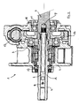
- the assistance module 2 comprises a tubular input shaft 4, and an output member here constituted by the pinion 3 itself, the input shaft 4 and the pinion 3 being rotatably mounted along a common axis A in 5.
- the input shaft 4 is connected in rotation, by its end remote from the pinion 3, to the steering column (not shown) of the vehicle concerned, while the pinion 3 engages with the rack (not shown) of the steering.
- the input shaft 4 and the pinion 3 are connected by means of a torsion bar 6 arranged along the axis A.
- One end of the torsion bar 6 is embedded in the bottom of a central recess 7 of the pinion 3, while the other end of the torsion bar 6 is rotatably connected by a pin 8 to the outer part of the input shaft 4.
- the pinion 3 is guided in rotation in the casing 5 by two rolling bearings 9 and 11, axially spaced.
- the input shaft 4 is guided in rotation in the housing 5 by an outer rolling bearing 10; this input shaft 4 is also guided in rotation relative to the pinion 3 by a smooth bearing 12 inside, located in the central recess 7 of the pinion 3.
- the housing 5 still contains a worm gear 13 and tangent wheel 14.
- the worm 13 is coupled to the shaft of an electric motor assistance (not shown ), while the tangent wheel 14 is mounted around the pinion 3 and rotatably connected thereto.
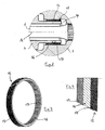
- the invention is more particularly concerned with the structure of the inner plain bearing 12, shown in detail on the Figures 2 to 4 .
- the plain bearing 12 in the form of a flat strip wound on itself, consists of three superimposed layers, designated according to their position (with respect to the axis A) as outer layer 15, intermediate layer 16 and inner layer 17 .
- the outer layer 15 is an elastomeric layer, with a damping function, which seats against the wall of the central recess 7 of the pinion 3.
- the intermediate layer 16 is a metal layer, in particular a steel layer.
- the inner layer 17 is a layer of polytetrafluoroethylene (PTFE), having good sliding qualities vis-à-vis the inner end of the input shaft 4 it surrounds.
- PTFE polytetrafluoroethylene
- the latter carries, through its outer elastomer layer 15, a damping function between the input shaft 4 and the pinion 3, where a suppression of metallic contact noises.
- the invention is not limited to the sole embodiment of this assistance module, described above as an example, it encompasses all the variants of embodiment and application respecting the same principle.
- the particular materials indicated are replaceable by all equivalent materials.
- the assistance module according to the invention could be used for any type of power steering, whether it is electric, hydraulic or other, adapting if necessary the output member.
- the output member would not be a pinion but an output shaft of the assistance module, coupled to an intermediate shaft.
Description
La présente invention se rapporte, d'une manière générale, aux systèmes de direction assistée équipant les véhicules automobiles. Plus particulièrement, cette invention a pour objet un module d'assistance, c'est-à-dire un sous-ensemble du système de direction assistée dont le rôle est de transmettre un couple d'assistance à la colonne de direction ou au pignon de direction, tout en déterminant le couple au volant pour asservir le couple d'assistance au couple au volant. Un tel module d'assistance est notamment applicable à une direction assistée électrique, dans laquelle un moteur électrique fournit le couple d'assistance transmis par ce module.The present invention relates, in general, to power steering systems fitted to motor vehicles. More particularly, this invention relates to an assistance module, that is to say a subset of the power steering system whose role is to transmit a torque of assistance to the steering column or pinion direction, while determining the steering wheel torque to enslave the torque assist torque steering wheel. Such an assistance module is particularly applicable to an electric power steering, in which an electric motor provides the assistance torque transmitted by this module.
Un module d'assistance, destiné à une direction assistée électrique, comprend un arbre d'entrée et un organe de sortie montés rotatifs sensiblement suivant un axe commun à l'intérieur d'un carter. L'arbre d'entrée est relié au volant de conduite du véhicule par l'intermédiaire de la colonne de direction, cet arbre d'entrée étant guidé en rotation dans le carter par un palier extérieur. L'organe de sortie est un arbre de sortie intermédiaire ou un pignon venant directement en prise avec la crémaillère de la direction, cet organe de sortie étant guidé en rotation dans le carter par au moins un autre palier. L'arbre d'entrée et l'organe de sortie sont liés par l'intermédiaire d'une barre de torsion, disposée axialement, à l'aide de laquelle le couple au volant peut être déterminé.An assistance module, intended for electric power steering, comprises an input shaft and an output member rotatably mounted substantially along a common axis inside a housing. The input shaft is connected to the steering wheel of the vehicle through the steering column, the input shaft being guided in rotation in the housing by an outer bearing. The output member is an intermediate output shaft or pinion directly engaging the rack of the direction, this output member being guided in rotation in the housing by at least one other bearing. The input shaft and the output member are connected by means of an axially disposed torsion bar with which the steering wheel torque can be determined.
L'extrémité intérieure de l'arbre d'entrée est engagée dans un évidement central de l'organe de sortie, et se trouve aussi guidée en rotation relativement à cet organe de sortie par un palier intérieur, en particulier un palier lisse.The inner end of the input shaft is engaged in a central recess of the output member, and is also guided in rotation relative to this output member by an inner bearing, in particular a sliding bearing.
Le couple d'assistance est transmis à l'organe de sortie, depuis le moteur électrique d'assistance, par l'intermédiaire d'un réducteur à engrenages qui est notamment un réducteur à vis sans fin et roue tangente, la vis sans fin étant accouplée au moteur et la roue tangente étant solidaire en rotation de l'organe de sortie.The assistance torque is transmitted to the output member, from the electric assistance motor, via a gear reducer which is in particular a worm gear and tangent wheel, the worm being coupled to the motor and the tangent wheel being integral in rotation with the output member.
Un module d'assistance ainsi constitué est divulgué, par exemple, par le brevet français
Un tel module d'assistance nécessite la présence d'un jeu entre l'arbre d'entrée et le palier intérieur de guidage de cet arbre relativement à l'organe de sortie, de manière à éviter les frottements entre ces deux éléments afin de pouvoir déterminer avec précision le couple au volant à l'aide de la barre de torsion. Toutefois, l'existence du jeu et les déplacements radiaux autorisés par ce jeu sont susceptibles, dans certaines conditions de roulage du véhicule, d'engendrer des bruits et vibrations parasites.Such an assistance module requires the presence of a clearance between the input shaft and the inner bearing guide of this shaft relative to the output member, so as to avoid friction between these two elements in order to be able to accurately determine the torque at the steering wheel using the torsion bar. However, the existence of the game and the radial displacements authorized by this game are likely, under certain conditions of driving the vehicle, to generate noise and parasitic vibrations.
Afin de limiter de tels bruits et vibrations, tout en conservant des frottements négligeables entre l'arbre d'entrée et le palier intérieur, le document de brevet précité
Une telle réalisation nécessite ainsi l'insertion d'un joint torique dans une gorge correspondante, donc l'ajout et le montage d'un élément supplémentaire. De plus, la gorge annulaire creusée dans l'arbre d'entrée ou dans le palier intérieur, pour loger et retenir le joint, est susceptible de fragiliser l'un ou l'autre de ces composants.Such an embodiment thus requires the insertion of an O-ring in a corresponding groove, thus the addition and mounting of an additional element. In addition, the annular groove dug in the input shaft or the inner bearing, to accommodate and retain the seal, is likely to weaken one or other of these components.
La présente invention vise à éliminer ces inconvénients, en fournissant une solution améliorée pour le guidage en rotation amorti à réaliser entre l'arbre d'entrée et l'organe de sortie du module d'assistance.The present invention aims to eliminate these disadvantages by providing an improved solution for the cushioned rotation guidance to be provided between the input shaft and the output member of the assistance module.
A cet effet, l'invention a pour objet un module d'assistance pour système de direction assistée de véhicule automobile, le module comprenant, au moins partiellement logés à l'intérieur d'un carter, un arbre d'entrée et un organe de sortie tel qu'un arbre de sortie ou un pignon, montés rotatifs sensiblement suivant un axe commun et liés par l'intermédiaire d'une barre de torsion disposée suivant ledit axe, l'arbre d'entrée étant guidé en rotation dans le carter par un palier extérieur, et étant guidé aussi en rotation relativement à l'organe de sortie par un palier intérieur, des moyens d'amortissement élastiques étant associés au palier intérieur, ce module d'assistance étant essentiellement caractérisé par le fait que lesdits moyens d'amortissement élastiques sont intégrés au palier intérieur.For this purpose, the subject of the invention is an assistance module for a motor vehicle power steering system, the module comprising, at least partially housed inside a housing, an input shaft and a control member. output such as an output shaft or pinion, rotatably mounted substantially along a common axis and connected via a torsion bar disposed along said axis, the input shaft being guided in rotation in the housing by an outer bearing, and being also guided in rotation relative to the output member by an inner bearing, elastic damping means being associated with the inner bearing, this assistance module being essentially characterized by the fact that said means of Elastic dampings are integrated in the inner bearing.
Ainsi, l'idée inventive consiste à réaliser un palier avec fonction d'amortissement intégrée, permettant d'obtenir une réduction des frottements et des bruits de contact entre l'arbre d'entrée et l'organe de sortie, en rendant inutile l'ajout d'un joint annulaire et la réalisation d'une gorge pour le montage du joint.Thus, the inventive idea is to achieve a bearing with integrated damping function, to obtain a reduction of friction and contact noise between the input shaft and the output member, by making unnecessary the addition of an annular seal and the realization of a groove for mounting the seal.
Pour l'intégration de la fonction d'amortissement, le palier intérieur comporte avantageusement, dans sa structure, au moins une couche d'amortissement, notamment en élastomère.For the integration of the damping function, the inner bearing advantageously comprises, in its structure, at least one damping layer, in particular of elastomer.
Dans une forme de réalisation préférée de l'invention, le palier intérieur se compose de trois couches coaxiales, à savoir :
- la couche d'amortissement en élastomère, située le plus à l'extérieur donc du côté de l'organe de sortie ;
- une couche métallique telle qu'en acier, située en position intermédiaire, et
- une couche en matériau à faible coefficient de frottement, tel que polytétrafluoréthylène (PTFE), située le plus à l'intérieur donc du côté de l'arbre d'entrée.
- the elastomer damping layer, located the outermost so the side of the output member;
- a metal layer such as steel, located in an intermediate position, and
- a layer of material with a low coefficient of friction, such as polytetrafluoroethylene (PTFE), which is the innermost one, therefore on the side of the input shaft.
La couche extérieure en élastomère réalise l'amortissement souhaité. La couche intermédiaire métallique confère au palier une tenue ou rigidité suffisante. La couche intérieure limite les frottements pour conserver une bonne précision de détermination du couple au volant.The elastomeric outer layer provides the desired damping. The intermediate metal layer gives the bearing sufficient strength or rigidity. The inner layer limits friction to maintain good steering wheel torque accuracy.
De toute façon, l'invention sera bien comprise à l'aide de la description qui suit en référence au dessin schématique annexé représentant, à titre d'exemple non limitatif, une forme d'exécution de ce module d'assistance.
-
Figure 1 est une vue en coupe longitudinale d'un module d'assistance selon l'invention ; -
Figure 2 représente, à échelle agrandie, un détail de lafigure 1 ; -
Figure 3 est une vue en perspective du palier intérieur seul ; -
Figure 4 est une vue en section du palier intérieur. - La
figure 1 représente un module d'assistance, désigné dans son ensemble par lerepère 2, qui appartient à un système de direction assistée électrique agissant sur le pignon dedirection 3.
-
Figure 1 is a longitudinal sectional view of an assistance module according to the invention; -
Figure 2 represents, on an enlarged scale, a detail of thefigure 1 ; -
Figure 3 is a perspective view of the inner bearing alone; -
Figure 4 is a sectional view of the inner bearing. - The
figure 1 represents an assistance module, generally designated byreference numeral 2, which belongs to an electric power steering system acting on thesteering pinion 3.
Le module d'assistance 2 comprend un arbre d'entrée 4 tubulaire, et un organe de sortie constitué ici par le pignon 3 lui-même, l'arbre d'entrée 4 et le pignon 3 étant montés rotatifs suivant un axe commun A dans un carter 5. En position montée, l'arbre d'entrée 4 est lié en rotation, par son extrémité éloignée du pignon 3, à la colonne de direction (non représentée) du véhicule concerné, tandis que le pignon 3 vient en prise avec la crémaillère (non représentée) de la direction.The
L'arbre d'entrée 4 et le pignon 3 sont liés par l'intermédiaire d'une barre de torsion 6 disposée suivant l'axe A. Une extrémité de la barre de torsion 6 est encastrée au fond d'un évidement central 7 du pignon 3, tandis que l'autre extrémité de la barre de torsion 6 est liée en rotation, par une goupille 8, à la partie extérieure de l'arbre d'entrée 4.The
Le pignon 3 est guidé en rotation dans le carter 5 par deux paliers à roulement 9 et 11, espacés axialement. L'arbre d'entrée 4 est guidé en rotation dans le carter 5 par un palier à roulement 10 extérieur ; cet arbre d'entrée 4 est aussi guidé en rotation relativement au pignon 3 par un palier lisse 12 intérieur, situé dans l'évidement central 7 du pignon 3.The
S'agissant ici d'une direction assistée électrique, le carter 5 renferme encore un réducteur à vis sans fin 13 et roue tangente 14. La vis sans fin 13 est accouplée à l'arbre d'un moteur électrique d'assistance (non représenté), tandis que la roue tangente 14 est montée autour du pignon 3 et liée en rotation à ce dernier.Concerning here an electric power steering, the housing 5 still contains a
L'invention s'intéresse plus particulièrement à la structure du palier lisse 12 intérieur, représenté en détail sur les
Le palier lisse 12, en forme de bande plate enroulée sur elle-même, se compose de trois couches superposées, désignées en fonction de leur position (par rapport à l'axe A) comme couche extérieure 15, couche intermédiaire 16 et couche intérieure 17.The plain bearing 12, in the form of a flat strip wound on itself, consists of three superimposed layers, designated according to their position (with respect to the axis A) as
La couche extérieure 15 est une couche en élastomère, à fonction d'amortissement, qui prend place face à la paroi de l'évidement central 7 du pignon 3.The
La couche intermédiaire 16 est une couche en métal, en particulier une couche en acier.The
La couche intérieure 17 est une couche en polytétrafluoréthylène (PTFE), présentant de bonnes qualités de glissement vis-à-vis de l'extrémité intérieure de l'arbre d'entrée 4 qu'elle entoure.The
Ainsi, sans augmenter les frottements entre l'arbre d'entrée 4 et le palier lisse 12 intérieur, ce dernier réalise par sa couche extérieure 15 en élastomère une fonction d'amortissement entre l'arbre d'entrée 4 et le pignon 3, d'où une suppression des bruits de contact métalliques.Thus, without increasing the friction between the
Comme il va de soi, l'invention ne se limite pas à la seule forme d'exécution de ce module d'assistance, décrite ci-dessus à titre d'exemple, elle en embrasse au contraire toutes les variantes de réalisation et d'application respectant le même principe. C'est ainsi notamment que les matières particulières indiquées sont remplaçables par toutes matières équivalentes. Dans le même ordre d'idées, le module d'assistance selon l'invention pourrait être utilisé pour tout type de direction assistée, que celle-ci soit électrique, hydraulique ou autre, en adaptant si nécessaire l'organe de sortie. En particulier, dans le cas d'une direction assistée électrique agissant sur la colonne de direction, l'organe de sortie ne serait pas un pignon mais un arbre de sortie du module d'assistance, accouplé à un arbre intermédiaire.As goes without saying, the invention is not limited to the sole embodiment of this assistance module, described above as an example, it encompasses all the variants of embodiment and application respecting the same principle. In particular, the particular materials indicated are replaceable by all equivalent materials. In the same vein, the assistance module according to the invention could be used for any type of power steering, whether it is electric, hydraulic or other, adapting if necessary the output member. In particular, in the case of an electric power steering acting on the steering column, the output member would not be a pinion but an output shaft of the assistance module, coupled to an intermediate shaft.
Claims (3)
- An assistance module for assisted steering system of motor vehicle, the module (2) comprising, at least partially housed inside a casing (5), an inlet shaft (4) and an outlet member such as an outlet shaft or a pinion (3), rotatably mounted substantially along a common axis (A) and connected by means of a torsion bar (6) disposed along said axis (A), the inlet shaft (4) being guided in rotation in the casing (5) by an external bearing (10), and being also guided in rotation relatively to the outlet member (3) by an internal bearing (12), elastic damping means being associated to the internal bearing (12), characterized in that said elastic damping means (15) are integrated to the internal bearing (12).
- The assistance module according to claim 1, characterized in that the internal bearing (12) comprises, in its structure, at least one damping layer (15), in particular in elastomer.
- The assistance module according to claim 2, characterized in that the internal bearing (12) is composed of three coaxial layers, namely:- the damping layer (15) in elastomer, located the most outwardly hence on the side of the outlet member (3),- a metal layer (16) such as in steel, located in intermediate position, and- a layer in a material of low friction coefficient (17), such as polytetrafluoroethylene (PTFE), located the most inwardly hence on the side of the inlet shaft (4).
Priority Applications (1)
| Application Number | Priority Date | Filing Date | Title |
|---|---|---|---|
| PL12190860T PL2591982T3 (en) | 2011-11-08 | 2012-10-31 | Assistance module for a power steering system of a vehicle |
Applications Claiming Priority (1)
| Application Number | Priority Date | Filing Date | Title |
|---|---|---|---|
| FR1160144A FR2982231B1 (en) | 2011-11-08 | 2011-11-08 | ASSISTANCE MODULE FOR VEHICLE ASSISTED STEERING SYSTEM |
Publications (2)
| Publication Number | Publication Date |
|---|---|
| EP2591982A1 EP2591982A1 (en) | 2013-05-15 |
| EP2591982B1 true EP2591982B1 (en) | 2015-03-25 |
Family
ID=47071193
Family Applications (1)
| Application Number | Title | Priority Date | Filing Date |
|---|---|---|---|
| EP12190860.2A Active EP2591982B1 (en) | 2011-11-08 | 2012-10-31 | Assistance module for a power steering system of a vehicle |
Country Status (3)
| Country | Link |
|---|---|
| EP (1) | EP2591982B1 (en) |
| FR (1) | FR2982231B1 (en) |
| PL (1) | PL2591982T3 (en) |
Families Citing this family (3)
| Publication number | Priority date | Publication date | Assignee | Title |
|---|---|---|---|---|
| WO2015133167A1 (en) | 2014-03-05 | 2015-09-11 | 日本精工株式会社 | Electric power steering device and method for assembling same |
| CN108639144A (en) * | 2018-04-18 | 2018-10-12 | 奇瑞汽车股份有限公司 | A kind of electric steering column output shaft fixing device |
| DE102022111141A1 (en) | 2022-05-05 | 2023-11-09 | Schaeffler Technologies AG & Co. KG | Torsional vibration damper with two-part shaft |
Family Cites Families (3)
| Publication number | Priority date | Publication date | Assignee | Title |
|---|---|---|---|---|
| DE1525041A1 (en) * | 1966-03-30 | 1969-08-14 | Boge Gmbh | Elastic slide bearing for oscillating movements, especially for the storage of handlebars on motor vehicles |
| JP3823018B2 (en) * | 2000-09-08 | 2006-09-20 | 株式会社ジェイテクト | Electric power steering device |
| FR2920390B1 (en) * | 2007-09-05 | 2009-12-04 | Jtekt Europe Sas | ASSISTED ASSISTANCE MODULE FOR MOTOR VEHICLE ASSISTED STEERING |
-
2011
- 2011-11-08 FR FR1160144A patent/FR2982231B1/en not_active Expired - Fee Related
-
2012
- 2012-10-31 EP EP12190860.2A patent/EP2591982B1/en active Active
- 2012-10-31 PL PL12190860T patent/PL2591982T3/en unknown
Also Published As
| Publication number | Publication date |
|---|---|
| FR2982231A1 (en) | 2013-05-10 |
| PL2591982T3 (en) | 2015-08-31 |
| FR2982231B1 (en) | 2013-11-08 |
| EP2591982A1 (en) | 2013-05-15 |
Similar Documents
| Publication | Publication Date | Title |
|---|---|---|
| EP2490928B1 (en) | Push device with clearance compensation for rack-and-pinion steering of a motor vehicle | |
| FR2853876A1 (en) | Steering device for vehicle, has speed reduction mechanism with pulleys and belt where belt is toothed helicoidal belt, and pulleys are constituted by toothed helicoidal pulleys engaging with helicoidal belt | |
| EP2591982B1 (en) | Assistance module for a power steering system of a vehicle | |
| EP2350495B1 (en) | Off-centred pusher device for steering an automobile | |
| FR3057232B1 (en) | STEERING LINK WITH ELASTIC SHOCK ABSORBER PROTECTED UNDER DIRECTION BOX BELLOW | |
| FR2911171A1 (en) | Mechanical speed reducer for power steering system, has elastic clearance absorbing unit disposed at predetermined position of casing wall of guiding bearing to press bearing in direction of reduction of distance of inter axial | |
| FR2937607A1 (en) | Auger and worm wheel type mechanical speed reducer for use in motor vehicle, has clearance retrieving body including primary cup engaged against bearing of auger and secondary cup positioned against bore of casing | |
| EP1955929B1 (en) | Motor assembly and reduction gear | |
| FR2924083A1 (en) | Rack and pinion type steering device for motor vehicle, has main bearing located in open-necked area with teeth, and constituted by ring presenting flat surface parallel to other flat surface in which crowns of teeth are located | |
| FR2916179A1 (en) | POWER ASSISTED STEERING OF A MOTOR VEHICLE WITHOUT TORSION BAR | |
| FR2920390A1 (en) | Assistance module for e.g. electrical power steering, of motor vehicle, has input shaft rotatably guided in case by external bearing and in output unit by internal bearing, and elastic joint placed between input shaft and internal bearing | |
| FR2935669A1 (en) | Electric power steering component for use on steering column of motor vehicle, has elastic dampening element i.e. elastomer O-ring joint, arranged among end of input shaft and nozzle needles of needle bearing | |
| EP3580082B1 (en) | Radial bearing arrangement of a transmission shaft of a vehicle, with a flange for the radial immobilisation of the rolling bearing | |
| EP2529996B1 (en) | Locking device for a steering system of a motor vehicle | |
| FR2861040A1 (en) | Rack and pinion drive assembly for rack and pinion steering gear of motor vehicle, has steering rack including tooth engaged with teeth of pinion, and flexible damping unit inserted between base of housing and part of tooth | |
| FR2859439A1 (en) | Motor vehicle steering rack pusher has body with one or more overmoulded guides of elastically deformable material | |
| FR2908724A1 (en) | Electrical power steering module for motor vehicle, has nut and annular shoulder axially retaining rolling bearing on corresponding end of steering pinion and on casing, where bearing with null clearance is located outside pinion | |
| FR2962508A1 (en) | Push rod device for e.g. hydraulic power-assisted steering gear of motor vehicle, has spring unit including springs arranged on sides of central axis of rod body in opposed positions along plane containing longitudinal axis of rack | |
| FR3137652A1 (en) | Speed reducer with backlash adjustment for electric power steering | |
| FR2862038A1 (en) | Steering system for motor vehicle, has steering bar including screw, locked in rotation, contacting with screw nut, locked in axial translation, where screw nut is rotatably mounted and coupled with steering column | |
| WO2021229175A1 (en) | Reducer having an electric power steering system and electric power steering system | |
| FR2975362A1 (en) | DIRECTION WITH RACK OF MOTOR VEHICLE | |
| FR2863240A1 (en) | Plunger line for motor vehicle`s rack-and-pinion steering gear, has rotating carrier unit with carrying surface that is covered by flexible annular unit made up of elastically deformable material | |
| FR2726610A1 (en) | DEVICE FOR COUPLING BETWEEN TWO TREES COMPRISING CIRCUMFERENTIAL ELASTIC DAMPING MEANS AND AXIAL ACTING ELASTIC MEANS | |
| EP2452862B1 (en) | Automobile steering gearbox with variable cross-section |
Legal Events
| Date | Code | Title | Description |
|---|---|---|---|
| PUAI | Public reference made under article 153(3) epc to a published international application that has entered the european phase |
Free format text: ORIGINAL CODE: 0009012 |
|
| AK | Designated contracting states |
Kind code of ref document: A1 Designated state(s): AL AT BE BG CH CY CZ DE DK EE ES FI FR GB GR HR HU IE IS IT LI LT LU LV MC MK MT NL NO PL PT RO RS SE SI SK SM TR |
|
| AX | Request for extension of the european patent |
Extension state: BA ME |
|
| 17P | Request for examination filed |
Effective date: 20131009 |
|
| RBV | Designated contracting states (corrected) |
Designated state(s): AL AT BE BG CH CY CZ DE DK EE ES FI FR GB GR HR HU IE IS IT LI LT LU LV MC MK MT NL NO PL PT RO RS SE SI SK SM TR |
|
| GRAP | Despatch of communication of intention to grant a patent |
Free format text: ORIGINAL CODE: EPIDOSNIGR1 |
|
| RIC1 | Information provided on ipc code assigned before grant |
Ipc: B62D 6/10 20060101AFI20140930BHEP Ipc: B62D 5/04 20060101ALI20140930BHEP |
|
| INTG | Intention to grant announced |
Effective date: 20141013 |
|
| GRAS | Grant fee paid |
Free format text: ORIGINAL CODE: EPIDOSNIGR3 |
|
| GRAA | (expected) grant |
Free format text: ORIGINAL CODE: 0009210 |
|
| AK | Designated contracting states |
Kind code of ref document: B1 Designated state(s): AL AT BE BG CH CY CZ DE DK EE ES FI FR GB GR HR HU IE IS IT LI LT LU LV MC MK MT NL NO PL PT RO RS SE SI SK SM TR |
|
| REG | Reference to a national code |
Ref country code: GB Ref legal event code: FG4D Free format text: NOT ENGLISH |
|
| REG | Reference to a national code |
Ref country code: CH Ref legal event code: EP |
|
| REG | Reference to a national code |
Ref country code: IE Ref legal event code: FG4D Free format text: LANGUAGE OF EP DOCUMENT: FRENCH |
|
| REG | Reference to a national code |
Ref country code: DE Ref legal event code: R096 Ref document number: 602012006131 Country of ref document: DE Effective date: 20150507 |
|
| REG | Reference to a national code |
Ref country code: AT Ref legal event code: REF Ref document number: 717699 Country of ref document: AT Kind code of ref document: T Effective date: 20150515 |
|
| PG25 | Lapsed in a contracting state [announced via postgrant information from national office to epo] |
Ref country code: HR Free format text: LAPSE BECAUSE OF FAILURE TO SUBMIT A TRANSLATION OF THE DESCRIPTION OR TO PAY THE FEE WITHIN THE PRESCRIBED TIME-LIMIT Effective date: 20150325 Ref country code: FI Free format text: LAPSE BECAUSE OF FAILURE TO SUBMIT A TRANSLATION OF THE DESCRIPTION OR TO PAY THE FEE WITHIN THE PRESCRIBED TIME-LIMIT Effective date: 20150325 Ref country code: LT Free format text: LAPSE BECAUSE OF FAILURE TO SUBMIT A TRANSLATION OF THE DESCRIPTION OR TO PAY THE FEE WITHIN THE PRESCRIBED TIME-LIMIT Effective date: 20150325 Ref country code: SE Free format text: LAPSE BECAUSE OF FAILURE TO SUBMIT A TRANSLATION OF THE DESCRIPTION OR TO PAY THE FEE WITHIN THE PRESCRIBED TIME-LIMIT Effective date: 20150325 |
|
| REG | Reference to a national code |
Ref country code: AT Ref legal event code: MK05 Ref document number: 717699 Country of ref document: AT Kind code of ref document: T Effective date: 20150325 |
|
| REG | Reference to a national code |
Ref country code: LT Ref legal event code: MG4D |
|
| PG25 | Lapsed in a contracting state [announced via postgrant information from national office to epo] |
Ref country code: LV Free format text: LAPSE BECAUSE OF FAILURE TO SUBMIT A TRANSLATION OF THE DESCRIPTION OR TO PAY THE FEE WITHIN THE PRESCRIBED TIME-LIMIT Effective date: 20150325 Ref country code: GR Free format text: LAPSE BECAUSE OF FAILURE TO SUBMIT A TRANSLATION OF THE DESCRIPTION OR TO PAY THE FEE WITHIN THE PRESCRIBED TIME-LIMIT Effective date: 20150626 Ref country code: RS Free format text: LAPSE BECAUSE OF FAILURE TO SUBMIT A TRANSLATION OF THE DESCRIPTION OR TO PAY THE FEE WITHIN THE PRESCRIBED TIME-LIMIT Effective date: 20150325 |
|
| REG | Reference to a national code |
Ref country code: PL Ref legal event code: T3 |
|
| PG25 | Lapsed in a contracting state [announced via postgrant information from national office to epo] |
Ref country code: NL Free format text: LAPSE BECAUSE OF FAILURE TO SUBMIT A TRANSLATION OF THE DESCRIPTION OR TO PAY THE FEE WITHIN THE PRESCRIBED TIME-LIMIT Effective date: 20150325 |
|
| PG25 | Lapsed in a contracting state [announced via postgrant information from national office to epo] |
Ref country code: ES Free format text: LAPSE BECAUSE OF FAILURE TO SUBMIT A TRANSLATION OF THE DESCRIPTION OR TO PAY THE FEE WITHIN THE PRESCRIBED TIME-LIMIT Effective date: 20150325 Ref country code: RO Free format text: LAPSE BECAUSE OF FAILURE TO SUBMIT A TRANSLATION OF THE DESCRIPTION OR TO PAY THE FEE WITHIN THE PRESCRIBED TIME-LIMIT Effective date: 20150325 Ref country code: SK Free format text: LAPSE BECAUSE OF FAILURE TO SUBMIT A TRANSLATION OF THE DESCRIPTION OR TO PAY THE FEE WITHIN THE PRESCRIBED TIME-LIMIT Effective date: 20150325 Ref country code: EE Free format text: LAPSE BECAUSE OF FAILURE TO SUBMIT A TRANSLATION OF THE DESCRIPTION OR TO PAY THE FEE WITHIN THE PRESCRIBED TIME-LIMIT Effective date: 20150325 Ref country code: PT Free format text: LAPSE BECAUSE OF FAILURE TO SUBMIT A TRANSLATION OF THE DESCRIPTION OR TO PAY THE FEE WITHIN THE PRESCRIBED TIME-LIMIT Effective date: 20150727 |
|
| PG25 | Lapsed in a contracting state [announced via postgrant information from national office to epo] |
Ref country code: AT Free format text: LAPSE BECAUSE OF FAILURE TO SUBMIT A TRANSLATION OF THE DESCRIPTION OR TO PAY THE FEE WITHIN THE PRESCRIBED TIME-LIMIT Effective date: 20150325 Ref country code: IS Free format text: LAPSE BECAUSE OF FAILURE TO SUBMIT A TRANSLATION OF THE DESCRIPTION OR TO PAY THE FEE WITHIN THE PRESCRIBED TIME-LIMIT Effective date: 20150725 |
|
| REG | Reference to a national code |
Ref country code: DE Ref legal event code: R097 Ref document number: 602012006131 Country of ref document: DE |
|
| PG25 | Lapsed in a contracting state [announced via postgrant information from national office to epo] |
Ref country code: DK Free format text: LAPSE BECAUSE OF FAILURE TO SUBMIT A TRANSLATION OF THE DESCRIPTION OR TO PAY THE FEE WITHIN THE PRESCRIBED TIME-LIMIT Effective date: 20150325 |
|
| PLBE | No opposition filed within time limit |
Free format text: ORIGINAL CODE: 0009261 |
|
| STAA | Information on the status of an ep patent application or granted ep patent |
Free format text: STATUS: NO OPPOSITION FILED WITHIN TIME LIMIT |
|
| 26N | No opposition filed |
Effective date: 20160105 |
|
| PG25 | Lapsed in a contracting state [announced via postgrant information from national office to epo] |
Ref country code: IT Free format text: LAPSE BECAUSE OF FAILURE TO SUBMIT A TRANSLATION OF THE DESCRIPTION OR TO PAY THE FEE WITHIN THE PRESCRIBED TIME-LIMIT Effective date: 20150325 |
|
| PG25 | Lapsed in a contracting state [announced via postgrant information from national office to epo] |
Ref country code: LU Free format text: LAPSE BECAUSE OF FAILURE TO SUBMIT A TRANSLATION OF THE DESCRIPTION OR TO PAY THE FEE WITHIN THE PRESCRIBED TIME-LIMIT Effective date: 20151031 Ref country code: SI Free format text: LAPSE BECAUSE OF FAILURE TO SUBMIT A TRANSLATION OF THE DESCRIPTION OR TO PAY THE FEE WITHIN THE PRESCRIBED TIME-LIMIT Effective date: 20150325 |
|
| REG | Reference to a national code |
Ref country code: CH Ref legal event code: PL |
|
| PG25 | Lapsed in a contracting state [announced via postgrant information from national office to epo] |
Ref country code: MC Free format text: LAPSE BECAUSE OF FAILURE TO SUBMIT A TRANSLATION OF THE DESCRIPTION OR TO PAY THE FEE WITHIN THE PRESCRIBED TIME-LIMIT Effective date: 20150325 |
|
| REG | Reference to a national code |
Ref country code: IE Ref legal event code: MM4A |
|
| PG25 | Lapsed in a contracting state [announced via postgrant information from national office to epo] |
Ref country code: CH Free format text: LAPSE BECAUSE OF NON-PAYMENT OF DUE FEES Effective date: 20151031 Ref country code: LI Free format text: LAPSE BECAUSE OF NON-PAYMENT OF DUE FEES Effective date: 20151031 |
|
| REG | Reference to a national code |
Ref country code: FR Ref legal event code: PLFP Year of fee payment: 5 |
|
| PG25 | Lapsed in a contracting state [announced via postgrant information from national office to epo] |
Ref country code: IE Free format text: LAPSE BECAUSE OF NON-PAYMENT OF DUE FEES Effective date: 20151031 |
|
| PG25 | Lapsed in a contracting state [announced via postgrant information from national office to epo] |
Ref country code: BG Free format text: LAPSE BECAUSE OF FAILURE TO SUBMIT A TRANSLATION OF THE DESCRIPTION OR TO PAY THE FEE WITHIN THE PRESCRIBED TIME-LIMIT Effective date: 20150325 Ref country code: SM Free format text: LAPSE BECAUSE OF FAILURE TO SUBMIT A TRANSLATION OF THE DESCRIPTION OR TO PAY THE FEE WITHIN THE PRESCRIBED TIME-LIMIT Effective date: 20150325 Ref country code: HU Free format text: LAPSE BECAUSE OF FAILURE TO SUBMIT A TRANSLATION OF THE DESCRIPTION OR TO PAY THE FEE WITHIN THE PRESCRIBED TIME-LIMIT; INVALID AB INITIO Effective date: 20121031 Ref country code: NO Free format text: LAPSE BECAUSE OF FAILURE TO SUBMIT A TRANSLATION OF THE DESCRIPTION OR TO PAY THE FEE WITHIN THE PRESCRIBED TIME-LIMIT Effective date: 20150625 |
|
| PG25 | Lapsed in a contracting state [announced via postgrant information from national office to epo] |
Ref country code: CY Free format text: LAPSE BECAUSE OF FAILURE TO SUBMIT A TRANSLATION OF THE DESCRIPTION OR TO PAY THE FEE WITHIN THE PRESCRIBED TIME-LIMIT Effective date: 20150325 |
|
| PG25 | Lapsed in a contracting state [announced via postgrant information from national office to epo] |
Ref country code: BE Free format text: LAPSE BECAUSE OF NON-PAYMENT OF DUE FEES Effective date: 20151031 |
|
| PG25 | Lapsed in a contracting state [announced via postgrant information from national office to epo] |
Ref country code: MT Free format text: LAPSE BECAUSE OF FAILURE TO SUBMIT A TRANSLATION OF THE DESCRIPTION OR TO PAY THE FEE WITHIN THE PRESCRIBED TIME-LIMIT Effective date: 20150325 |
|
| REG | Reference to a national code |
Ref country code: FR Ref legal event code: PLFP Year of fee payment: 6 |
|
| PG25 | Lapsed in a contracting state [announced via postgrant information from national office to epo] |
Ref country code: TR Free format text: LAPSE BECAUSE OF FAILURE TO SUBMIT A TRANSLATION OF THE DESCRIPTION OR TO PAY THE FEE WITHIN THE PRESCRIBED TIME-LIMIT Effective date: 20150325 Ref country code: MK Free format text: LAPSE BECAUSE OF FAILURE TO SUBMIT A TRANSLATION OF THE DESCRIPTION OR TO PAY THE FEE WITHIN THE PRESCRIBED TIME-LIMIT Effective date: 20150325 |
|
| REG | Reference to a national code |
Ref country code: FR Ref legal event code: PLFP Year of fee payment: 7 |
|
| PG25 | Lapsed in a contracting state [announced via postgrant information from national office to epo] |
Ref country code: AL Free format text: LAPSE BECAUSE OF FAILURE TO SUBMIT A TRANSLATION OF THE DESCRIPTION OR TO PAY THE FEE WITHIN THE PRESCRIBED TIME-LIMIT Effective date: 20150325 |
|
| PGFP | Annual fee paid to national office [announced via postgrant information from national office to epo] |
Ref country code: CZ Payment date: 20190918 Year of fee payment: 8 |
|
| PGFP | Annual fee paid to national office [announced via postgrant information from national office to epo] |
Ref country code: PL Payment date: 20190917 Year of fee payment: 8 |
|
| PGFP | Annual fee paid to national office [announced via postgrant information from national office to epo] |
Ref country code: GB Payment date: 20190830 Year of fee payment: 8 |
|
| GBPC | Gb: european patent ceased through non-payment of renewal fee |
Effective date: 20201031 |
|
| PG25 | Lapsed in a contracting state [announced via postgrant information from national office to epo] |
Ref country code: CZ Free format text: LAPSE BECAUSE OF NON-PAYMENT OF DUE FEES Effective date: 20201031 |
|
| PG25 | Lapsed in a contracting state [announced via postgrant information from national office to epo] |
Ref country code: GB Free format text: LAPSE BECAUSE OF NON-PAYMENT OF DUE FEES Effective date: 20201031 |
|
| PG25 | Lapsed in a contracting state [announced via postgrant information from national office to epo] |
Ref country code: PL Free format text: LAPSE BECAUSE OF NON-PAYMENT OF DUE FEES Effective date: 20201031 |
|
| PGFP | Annual fee paid to national office [announced via postgrant information from national office to epo] |
Ref country code: FR Payment date: 20230830 Year of fee payment: 12 |
|
| PGFP | Annual fee paid to national office [announced via postgrant information from national office to epo] |
Ref country code: DE Payment date: 20230829 Year of fee payment: 12 |