EP2591979B1 - Hilfsventil für hydraulische Servolenkung eines Kraftfahrzeugs - Google Patents
Hilfsventil für hydraulische Servolenkung eines Kraftfahrzeugs Download PDFInfo
- Publication number
- EP2591979B1 EP2591979B1 EP20120190863 EP12190863A EP2591979B1 EP 2591979 B1 EP2591979 B1 EP 2591979B1 EP 20120190863 EP20120190863 EP 20120190863 EP 12190863 A EP12190863 A EP 12190863A EP 2591979 B1 EP2591979 B1 EP 2591979B1
- Authority
- EP
- European Patent Office
- Prior art keywords
- rotor
- rotors
- jacket
- assistance
- valve
- Prior art date
- Legal status (The legal status is an assumption and is not a legal conclusion. Google has not performed a legal analysis and makes no representation as to the accuracy of the status listed.)
- Active
Links
Images




Classifications
-
- B—PERFORMING OPERATIONS; TRANSPORTING
- B62—LAND VEHICLES FOR TRAVELLING OTHERWISE THAN ON RAILS
- B62D—MOTOR VEHICLES; TRAILERS
- B62D5/00—Power-assisted or power-driven steering
- B62D5/06—Power-assisted or power-driven steering fluid, i.e. using a pressurised fluid for most or all the force required for steering a vehicle
- B62D5/08—Power-assisted or power-driven steering fluid, i.e. using a pressurised fluid for most or all the force required for steering a vehicle characterised by type of steering valve used
- B62D5/083—Rotary valves
-
- B—PERFORMING OPERATIONS; TRANSPORTING
- B62—LAND VEHICLES FOR TRAVELLING OTHERWISE THAN ON RAILS
- B62D—MOTOR VEHICLES; TRAILERS
- B62D5/00—Power-assisted or power-driven steering
- B62D5/06—Power-assisted or power-driven steering fluid, i.e. using a pressurised fluid for most or all the force required for steering a vehicle
- B62D5/09—Power-assisted or power-driven steering fluid, i.e. using a pressurised fluid for most or all the force required for steering a vehicle characterised by means for actuating valves
- B62D5/091—Hydraulic steer-by-wire systems, e.g. the valve being actuated by an electric motor
Definitions
- the present invention relates, in general, to hydraulic power steering systems, which equip motor vehicles. More particularly, this invention relates to an assistance valve, intended for a direction of hydraulic assistance of a motor vehicle.
- the two chambers 7 and 9 of the assistance cylinder 8 are separated by a piston 10, integral in translation with the rack 11.
- the four channels are connected by internal ducts mounted in the manner of a "Wheatstone bridge" (by analogy with a bridge of electrical resistances), according to the hydraulic diagram shown on the diagram. figure 1 , with four internal openings that open and close alternately two by two.
- the assistance valve being a rotary valve, its internal conduits and orifices are formed on a rotor and on a rotating sleeve coaxially surrounding the rotor, the rotor and the jacket being provided with respective grooves which may or may not be matched according to the angular position. relative rotor and the liner, to achieve simultaneous openings and closures of the orifices.
- two grooves on the rotor and two other grooves on the liner should be sufficient for proper hydraulic operation of the assist valve.
- the number of grooves must be at least six, so that the resultant radial forces due to pressure differences vanishes on the central axis of the valve.
- the patent document JP 2002-347636 clearly shows a known arrangement with six grooves. DE 10 2006 005653 A1 is considered the closest prior art, according to the preamble of claim 1.
- the rotary assist valve made according to the previously mentioned principle, is located on the vehicle at the junction of the steering column and the steering housing which houses the rack and the assistance cylinder.
- the rotor of the assist valve is connected, via a torsion bar, to the steering pinion which engages with the rack, while the valve jacket is rotatably connected directly with the pinion. direction.
- the outer end of the rotor is further rotatably connected to the steering column.
- the assistance valve provides a hydraulic fluid pressure which is an increasing function of the torque applied to this valve and deforming the torsion bar, thus a direct function of the torque exerted by the driver on the steering wheel.
- this traditional design mechanically links the assistance valve to the steering column as well as to the rack-and-pinion assembly of the steering system.
- the control of the rotating valve is thus performed in a manner invariably imposed by the adjacent mechanical elements and in particular by the instantaneous relative positions of these elements.
- the operation of the electric power steering is therefore ignoring certain parameters and is not optimized; in particular, the control movement of the rack by the assistance system may lack progressiveness and accuracy.
- An improvement route already proposed consists in mechanically separating the assistance valve from the steering column and the rack-and-pinion-cylinder assembly, the assistance valve thus becoming an autonomous member, whose control in translation or in rotation is performed by an electric motor or actuator - see for example patent documents EP 1 659 047 or US 2006/175118 , for a translation order, and patent documents DE 198 40625 and US 6,305,490 , for a control in rotation.
- the rotary valve can then be placed for example above the steering box, but away from the steering column, and be connected by short hydraulic conduits to the two chambers of the assistance cylinder.
- the angular control of such a rotary valve remains delicate. Indeed, the angular amplitude of the opening and closing movement is low and can not reach a value greater than 15 °, given the minimum number of six grooves to be provided on the rotor and on the sleeve to balance the forces as explained above.
- the present invention aims to eliminate these disadvantages, thus to allow a greater angular amplitude rotation for a rotary assist valve disengaged from the mechanical components of the steering system, while maintaining the balancing efforts.
- the subject of the invention is an assistance valve for steering with hydraulic assistance of a motor vehicle, the assistance valve being of rotary type and disengaged from the steering column, and this valve being controlled by motor means.
- electrical rotating at least one element such as rotor or jacket
- said assistance valve being essentially characterized in that it comprises two sets, hydraulically connected or not, each consisting of a rotor and a jacket surrounding the rotor, three grooves being provided on the outside of the rotor and on the inside of the liner of each assembly, and the electric motor means being provided for rotating the rotors or liners of the two aforementioned assemblies, each rotor-liner assembly being provided for supplying hydraulic fluid to one of the two chambers of an assistance cylinder.
- the inventive idea is to distribute the internal conduits and orifices of an assistance valve on two sets each consisting of a rotor and a liner, which reduces by six to three the number of grooves on each rotor and on each shirt.
- each set consisting of a rotor and a shirt is equivalent to a "half-bridge". Thanks to the reduction of number of grooves, it becomes possible to significantly increase the amplitude of rotation, this angular amplitude can become three or four times greater than that of the rotor of a traditional assistance valve, while maintaining the balance of efforts since three grooves are always planned.
- the two assemblies each composed of a rotor and a jacket, are arranged coaxially, and their respective rotary elements, rotors or jackets, are coupled together and to a single motor. electrical, common to these rotating elements and can be arranged along the same axis.
- the two rotors can be linked in rotation with each other and with a single electric motor, these two rotors rotating in respective fixed folders.
- the two rotors can be fixed, while the shirts are interconnected and rotate around the respective rotors, while being coupled to a single electric motor.
- the larger diameter of the sleeves allows them to rotate in a motorized manner with a reduction achieved by a toothed belt or by gears, which facilitates the adoption of a motor type "step by step” for their training.
- the term "rotor” does not mean a rotating element, but an inner element by reference to the sleeve surrounding this rotor).
- the intake and the hydraulic fluid outlets are advantageously situated on the fixed part, which comprises the jackets in the first case and the rotors in the second case, the union of the two rotor-jack assemblies functionally performing the equivalent of a valve four-way assistance, as described in the introduction with reference to the figure 1 , a single pump supplying both sets of hydraulic fluid.
- the rotary element such as rotor or jacket is coupled to a separate electric motor, and each of these two assemblies is also supplied with fluid. hydraulic by a separate pump.
- the double rotary valve thus obtained makes it possible to obtain variations of different and independent pressure in both chambers of the service cylinder, thereby creating an active cylinder chamber and a resistive jack chamber at the same time.
- this variant makes it possible to improve the performance of the steering system, in particular by limiting the upward forces in the steering wheel due to the poor condition of the roads and also facilitating steering in the movement of the rack, with improved progressivity and precision.
- a steering system of a motor vehicle includes a steering wheel 12 connected, by a steering column 13, to a steering pinion (not visible) engaged with the rack 11, mounted to be movable in translation in the longitudinal direction in a housing of direction 14.
- the two ends of the rack 11, external to the steering housing 14, are respectively coupled to two steering rods 15 and 16, respectively associated with the right and left 17 steered wheels of the vehicle.
- the steering casing 14 contains a double-acting hydraulic cylinder 8, designated as an assistance cylinder, which transmits to the rack 11 a force that amplifies the action exerted manually by the driver. of the vehicle on the driving wheel 12.
- the rotary assistance valve 19 is dissociated from the steering column 13 and the pinion-rack-jack assembly, this valve being controlled by electric motor means which rotate at least one of its elements, such as specified below.
- the rotary assist valve 19 is hydraulically equivalent to a four-way valve, with a first channel 1 for the admission of the fluid delivered by the pump 5, a second channel 2 for the return of this fluid to the reservoir 6 , a third channel 3 for supplying one of the chambers of the assistance cylinder 8, and a fourth channel 4 for supplying the other chamber of this cylinder.
- the rotary assist valve 19 is divided into two similar sets 20 and 21, comparable to two "half-bridges" hydraulically connected to each other. Both sets 20 and 21 are, one and the other, connected to the channels 1 and 2 respectively of admission of the fluid delivered by the pump 5 and return of this fluid to the reservoir 6.
- the first set 20 comprises the track 3 for feeding a chamber 7 of the assistance jack 8.
- the second set 21 comprises the track 4 for feeding the other chamber 9 of the same assistance jack 8.
- Each set 20 or 21 is composed of a cylindrical inner element called “rotor” 22, and an annular outer element called “liner” 23 which coaxially surrounds the rotor 22.
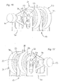
- the rotor 22, shown in FIGS. Figures 6 and 7 has on its periphery three grooves 24, 25 and 26.
- the sleeve 23, shown on the Figures 8 and 9 internally has three grooves 27, 28 and 29.
- the respective rotors 22 of the two assemblies 20 and 21 are arranged coaxially and mechanically coupled together, these rotors 22 being
- the respective jackets 23 of the two assemblies 20 and 21, surrounding the two rotors 22, are secured and fixedly mounted on the frame 30, these two jackets 23 being able to be joined together in a single fixed body, on which are placed the different channels 1 to 4.
- the set of two rotors 22 is coupled to a single electric motor 31, placed at one end of the assistance valve 19 coaxially with the rotors 22 and the shirts 23.
- the actuation of the electric motor 31 simultaneously rotates the two rotors 22 by rotating them inside the corresponding shirts 23. Consequently, in each set 20 or 21, the relative positions of the grooves 24, 25, 26 of the rotor 22 and the grooves 27, 28, 29 of the jacket 23 are modifiable, so as to manage the supply of the two chambers 7 and 9 of the assistance cylinder 8, depending on the need for assistance of each moment.
- the two rotors 22 are rotatably mounted relative to the frame 30, while the two shirts 23 which respectively surround the two rotors 22 are fixedly mounted on the frame 30.
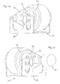
- the two motors 33 and 34 are placed at the ends of the assistance valve 19, coaxially with the two rotors 22, and are respectively coupled to these two rotors 22.
- the fixed liner 23 of the first assembly 20 here comprises a lane 1a for the admission of hydraulic fluid pressurized by a first pump, a lane 2a for the return of the fluid to the reservoir, and the lane 3 for the supply of the one of the chambers of the assistance cylinder.
- the fixed liner 23 of the second assembly 21 comprises a lane 1b for the admission of the hydraulic fluid pressurized by a second pump, a lane 2b for the return of fluid to the reservoir, and the lane 4 for the supply of the another chamber of the service cylinder.
- the figures 15 , 16 and 17 show a rotary assist valve 19 with two rotors 22 fixedly mounted on the frame 30, and two liners 23 which are rotatably mounted around the respective rotors 22.
- Two motors 33 and 34 rotate respectively the two jackets 23, via two toothed belts 35 and 36, respectively, which wind around the two jackets 23.
Landscapes
- Engineering & Computer Science (AREA)
- Chemical & Material Sciences (AREA)
- Combustion & Propulsion (AREA)
- Transportation (AREA)
- Mechanical Engineering (AREA)
- Multiple-Way Valves (AREA)
- Hydraulic Motors (AREA)
Claims (6)
- Servoventil für hydraulische Kraftfahrzeug-Servolenkung, wobei das Servoventil (19) von der Art eines Drehventils ist und von der Lenksäule (13) abgekoppelt ist, und wobei dieses Ventil durch Elektromotormittel gesteuert wird, die mindestens ein Element, wie etwa einen Rotor oder einen Mantel drehmäßig antreiben, dadurch gekennzeichnet, dass es zwei Einheiten (20, 21) umfasst, die hydraulisch verbunden sind oder nicht und jeweils aus einem Rotor (22) und einem den Rotor umgebenden Mantel (23) bestehen, wobei drei Nuten (24 bis 29) außen an dem Rotor (22) und innen an dem Mantel (23) jeder Einheit (20, 21) bereitgestellt werden, und wobei die Elektromotormittel (31; 33, 34) bereitgestellt werden, um die Rotoren (22) oder die Mäntel (23) der beiden genannten Einheiten drehmäßig anzutreiben, wobei jede Einheit aus Rotor und Mantel bereitgestellt wird, um eine der beiden Kammern (7, 9) eines Servozylinders (8) mit Hydraulikfluid zu versorgen.
- Servoventil nach Anspruch 1, dadurch gekennzeichnet, dass die beiden Einheiten (20, 21), die jeweils aus einem Rotor (22) und einem Mantel (23) bestehen, koaxial angeordnet sind, und dass ihre jeweiligen Drehelemente, Rotoren oder Mäntel, untereinander und mit einem einzigen Elektromotor (31) gekoppelt sind, der von diesen Drehelementen gemeinsam genutzt wird und entlang der gleichen Achse angeordnet sein kann.
- Servoventil nach Anspruch 2, dadurch gekennzeichnet, dass die beiden Rotoren (22) untereinander und mit einem einzigen Elektromotor (31) drehmäßig verbunden sind, wobei sich diese beiden Rotoren (22) in jeweiligen feststehenden Mänteln (23) drehen.
- Servoventil nach Anspruch 2, dadurch gekennzeichnet, dass die beiden Rotoren (22) feststehend sind, während die Mäntel (23) miteinander verbunden sind und sich um die jeweiligen Rotoren (22) drehen und dabei mit einem einzigen Elektromotor (31) gekoppelt sind.
- Servoventil nach einem der Ansprüche 1 bis 4, dadurch gekennzeichnet, dass sich der Einlass und die Ausgänge des Hydraulikfluids auf dem feststehenden Teil befinden, der die Mäntel (23) oder die Rotoren (22) umfasst, wobei die Vereinigung der beiden Einheiten (20, 21) aus Rotor und Mantel funktionsmäßig einem Vier-Wege- (1 bis 4) Servoventil (19) entspricht, wobei ein und dieselbe Pumpe (5) diese beiden Einheiten (20, 21) mit Hydraulikfluid versorgt.
- Servoventil nach Anspruch 1, dadurch gekennzeichnet, dass für jede der beiden Einheiten (20, 21), die aus einem Rotor (22) und einem Mantel (23) bestehen, das Drehelement, wie etwa der Rotor oder der Mantel, mit einem getrennten Elektromotor (33, 34) gekoppelt ist, und dass jede dieser beiden Einheiten (20, 21) auch durch eine getrennte Pumpe mit Hydraulikfluid versorgt wird.
Applications Claiming Priority (1)
| Application Number | Priority Date | Filing Date | Title |
|---|---|---|---|
| FR1160148A FR2982232B1 (fr) | 2011-11-08 | 2011-11-08 | Valve d'assistance pour direction a assistance hydraulique de vehicule automobile |
Publications (2)
| Publication Number | Publication Date |
|---|---|
| EP2591979A1 EP2591979A1 (de) | 2013-05-15 |
| EP2591979B1 true EP2591979B1 (de) | 2014-06-25 |
Family
ID=47071194
Family Applications (1)
| Application Number | Title | Priority Date | Filing Date |
|---|---|---|---|
| EP20120190863 Active EP2591979B1 (de) | 2011-11-08 | 2012-10-31 | Hilfsventil für hydraulische Servolenkung eines Kraftfahrzeugs |
Country Status (2)
| Country | Link |
|---|---|
| EP (1) | EP2591979B1 (de) |
| FR (1) | FR2982232B1 (de) |
Family Cites Families (8)
| Publication number | Priority date | Publication date | Assignee | Title |
|---|---|---|---|---|
| DE19542200C2 (de) * | 1995-11-13 | 2000-04-27 | Daimler Chrysler Ag | Servoventil |
| FR2752809B1 (fr) | 1996-09-04 | 1998-10-30 | Soc D Mecanique D Irigny | Valve d'assistance pour direction assistee de vehicule automobile |
| DE19840625C2 (de) | 1998-09-05 | 2002-07-04 | Daimler Chrysler Ag | Lenkventilanordnung eines hydraulischen Lenksystems |
| FR2810957B1 (fr) | 2000-06-28 | 2002-09-13 | Soc Mecanique Irigny | Valve d'assistance pour direction assistee hydraulique de vehicule automobile |
| JP4075326B2 (ja) * | 2001-05-28 | 2008-04-16 | ユニシア ジェーケーシー ステアリングシステム株式会社 | ステアリングダンパ |
| JP2005075093A (ja) | 2003-08-29 | 2005-03-24 | Koyo Seiko Co Ltd | パワーステアリングユニット |
| DE102006005653A1 (de) * | 2006-02-08 | 2007-08-30 | Zf Lenksysteme Gmbh | Hydraulische Hilfskraftlenkung |
| JP2013520367A (ja) * | 2010-02-27 | 2013-06-06 | アール.エイチ.シェパード カンパニー、インコーポレイテッド | 油圧パワーステアリング・システム |
-
2011
- 2011-11-08 FR FR1160148A patent/FR2982232B1/fr not_active Expired - Fee Related
-
2012
- 2012-10-31 EP EP20120190863 patent/EP2591979B1/de active Active
Also Published As
| Publication number | Publication date |
|---|---|
| FR2982232B1 (fr) | 2013-11-22 |
| EP2591979A1 (de) | 2013-05-15 |
| FR2982232A1 (fr) | 2013-05-10 |
Similar Documents
| Publication | Publication Date | Title |
|---|---|---|
| EP2445767B1 (de) | Bremssystem mit elektrischem bremsverstärker | |
| EP2245303B1 (de) | Wasserkraftmaschine als hilfe für das mechanische getriebe eines fahrzeuges | |
| EP3233553B1 (de) | Hydraulischer antrieb für fahrzeugrad | |
| EP1845016A1 (de) | Fahrwerk umfassend mehrere elektromechanische Ausrichtungsstellglieder | |
| FR2510506A1 (fr) | Systeme de direction permettant le braquage des roues avant et des roues arriere d'un vehicule | |
| FR2552389A1 (fr) | Systeme de direction assistee pour vehicule a l'aide d'un debit de fluide selectif vers un dispositif d'assistance | |
| EP3994341B1 (de) | Vorrichtung zur dämpfung eines wälzlagers mit einem durch einen flexiblen käfig geführten starren träger | |
| FR2586752A1 (fr) | Machine a pistons radiaux, a tensions de contact reduites | |
| EP3299656A1 (de) | Verbessertes bremssystem für hydraulische maschine | |
| CA2941804A1 (fr) | Relais d'accessoires pour moteur a turbine a gaz | |
| EP3870833B1 (de) | Verbesserter hydraulischer motor für ein lenkbares rad eines fahrzeugs | |
| FR3005028A1 (fr) | Axe de roue demontable pour train de vehicule | |
| EP3784901B1 (de) | Hydraulische anordnung für ein gelenktes rad eines fahrzeuges | |
| FR2967113A1 (fr) | Support de roue muni de conduits d'alimentation d'un appareil hydraulique | |
| EP2591979A1 (de) | Hilfsventil für hydraulische Servolenkung eines Kraftfahrzeugs | |
| WO2007087168A2 (en) | Rack and pinion steering assembly | |
| EP0119923B1 (de) | Servolenkung mit zentralem Abtrieb | |
| FR2988798A1 (fr) | Unite de puissance de vehicule du type a entrainement par arbre | |
| EP3134286B1 (de) | Antriebseinheit für eine motorwelle eines kraftfahrzeugs | |
| FR2916179A1 (fr) | Direction assistee de vehicule automobile sans barre de torsion | |
| FR2864458A1 (fr) | Dispositif d'assemblage d'un servomoteur pneumatique, procede d'assemblage, et servomoteur pneumatique. | |
| EP0136233B1 (de) | Kompakt-Servolenkungs-Mechanismus für Kraftfahrzeug | |
| EP0075519A2 (de) | Antriebsmechanismus mit Fluidhilfe, insbesondere für Kraftfahrzeugservolenkungssystem | |
| FR3151826A1 (fr) | Ensemble d’entrainement d’une colonne de direction | |
| EP3406901B1 (de) | Hydraulisches gerät, das einen verbesserten verteiler umfasst |
Legal Events
| Date | Code | Title | Description |
|---|---|---|---|
| PUAI | Public reference made under article 153(3) epc to a published international application that has entered the european phase |
Free format text: ORIGINAL CODE: 0009012 |
|
| AK | Designated contracting states |
Kind code of ref document: A1 Designated state(s): AL AT BE BG CH CY CZ DE DK EE ES FI FR GB GR HR HU IE IS IT LI LT LU LV MC MK MT NL NO PL PT RO RS SE SI SK SM TR |
|
| AX | Request for extension of the european patent |
Extension state: BA ME |
|
| 17P | Request for examination filed |
Effective date: 20131009 |
|
| RBV | Designated contracting states (corrected) |
Designated state(s): AL AT BE BG CH CY CZ DE DK EE ES FI FR GB GR HR HU IE IS IT LI LT LU LV MC MK MT NL NO PL PT RO RS SE SI SK SM TR |
|
| GRAP | Despatch of communication of intention to grant a patent |
Free format text: ORIGINAL CODE: EPIDOSNIGR1 |
|
| INTG | Intention to grant announced |
Effective date: 20140228 |
|
| GRAS | Grant fee paid |
Free format text: ORIGINAL CODE: EPIDOSNIGR3 |
|
| GRAA | (expected) grant |
Free format text: ORIGINAL CODE: 0009210 |
|
| AK | Designated contracting states |
Kind code of ref document: B1 Designated state(s): AL AT BE BG CH CY CZ DE DK EE ES FI FR GB GR HR HU IE IS IT LI LT LU LV MC MK MT NL NO PL PT RO RS SE SI SK SM TR |
|
| REG | Reference to a national code |
Ref country code: GB Ref legal event code: FG4D Free format text: NOT ENGLISH |
|
| REG | Reference to a national code |
Ref country code: CH Ref legal event code: EP |
|
| REG | Reference to a national code |
Ref country code: AT Ref legal event code: REF Ref document number: 674449 Country of ref document: AT Kind code of ref document: T Effective date: 20140715 |
|
| REG | Reference to a national code |
Ref country code: IE Ref legal event code: FG4D Free format text: LANGUAGE OF EP DOCUMENT: FRENCH |
|
| REG | Reference to a national code |
Ref country code: DE Ref legal event code: R096 Ref document number: 602012002227 Country of ref document: DE Effective date: 20140807 |
|
| PG25 | Lapsed in a contracting state [announced via postgrant information from national office to epo] |
Ref country code: GR Free format text: LAPSE BECAUSE OF FAILURE TO SUBMIT A TRANSLATION OF THE DESCRIPTION OR TO PAY THE FEE WITHIN THE PRESCRIBED TIME-LIMIT Effective date: 20140926 Ref country code: NO Free format text: LAPSE BECAUSE OF FAILURE TO SUBMIT A TRANSLATION OF THE DESCRIPTION OR TO PAY THE FEE WITHIN THE PRESCRIBED TIME-LIMIT Effective date: 20140925 Ref country code: CY Free format text: LAPSE BECAUSE OF FAILURE TO SUBMIT A TRANSLATION OF THE DESCRIPTION OR TO PAY THE FEE WITHIN THE PRESCRIBED TIME-LIMIT Effective date: 20140625 Ref country code: LT Free format text: LAPSE BECAUSE OF FAILURE TO SUBMIT A TRANSLATION OF THE DESCRIPTION OR TO PAY THE FEE WITHIN THE PRESCRIBED TIME-LIMIT Effective date: 20140625 Ref country code: FI Free format text: LAPSE BECAUSE OF FAILURE TO SUBMIT A TRANSLATION OF THE DESCRIPTION OR TO PAY THE FEE WITHIN THE PRESCRIBED TIME-LIMIT Effective date: 20140625 |
|
| REG | Reference to a national code |
Ref country code: AT Ref legal event code: MK05 Ref document number: 674449 Country of ref document: AT Kind code of ref document: T Effective date: 20140625 |
|
| REG | Reference to a national code |
Ref country code: NL Ref legal event code: VDEP Effective date: 20140625 |
|
| REG | Reference to a national code |
Ref country code: LT Ref legal event code: MG4D |
|
| PG25 | Lapsed in a contracting state [announced via postgrant information from national office to epo] |
Ref country code: RS Free format text: LAPSE BECAUSE OF FAILURE TO SUBMIT A TRANSLATION OF THE DESCRIPTION OR TO PAY THE FEE WITHIN THE PRESCRIBED TIME-LIMIT Effective date: 20140625 Ref country code: SE Free format text: LAPSE BECAUSE OF FAILURE TO SUBMIT A TRANSLATION OF THE DESCRIPTION OR TO PAY THE FEE WITHIN THE PRESCRIBED TIME-LIMIT Effective date: 20140625 Ref country code: LV Free format text: LAPSE BECAUSE OF FAILURE TO SUBMIT A TRANSLATION OF THE DESCRIPTION OR TO PAY THE FEE WITHIN THE PRESCRIBED TIME-LIMIT Effective date: 20140625 Ref country code: HR Free format text: LAPSE BECAUSE OF FAILURE TO SUBMIT A TRANSLATION OF THE DESCRIPTION OR TO PAY THE FEE WITHIN THE PRESCRIBED TIME-LIMIT Effective date: 20140625 |
|
| PG25 | Lapsed in a contracting state [announced via postgrant information from national office to epo] |
Ref country code: RO Free format text: LAPSE BECAUSE OF FAILURE TO SUBMIT A TRANSLATION OF THE DESCRIPTION OR TO PAY THE FEE WITHIN THE PRESCRIBED TIME-LIMIT Effective date: 20140625 Ref country code: ES Free format text: LAPSE BECAUSE OF FAILURE TO SUBMIT A TRANSLATION OF THE DESCRIPTION OR TO PAY THE FEE WITHIN THE PRESCRIBED TIME-LIMIT Effective date: 20140625 Ref country code: SK Free format text: LAPSE BECAUSE OF FAILURE TO SUBMIT A TRANSLATION OF THE DESCRIPTION OR TO PAY THE FEE WITHIN THE PRESCRIBED TIME-LIMIT Effective date: 20140625 Ref country code: PT Free format text: LAPSE BECAUSE OF FAILURE TO SUBMIT A TRANSLATION OF THE DESCRIPTION OR TO PAY THE FEE WITHIN THE PRESCRIBED TIME-LIMIT Effective date: 20141027 Ref country code: EE Free format text: LAPSE BECAUSE OF FAILURE TO SUBMIT A TRANSLATION OF THE DESCRIPTION OR TO PAY THE FEE WITHIN THE PRESCRIBED TIME-LIMIT Effective date: 20140625 |
|
| PG25 | Lapsed in a contracting state [announced via postgrant information from national office to epo] |
Ref country code: PL Free format text: LAPSE BECAUSE OF FAILURE TO SUBMIT A TRANSLATION OF THE DESCRIPTION OR TO PAY THE FEE WITHIN THE PRESCRIBED TIME-LIMIT Effective date: 20140625 Ref country code: IS Free format text: LAPSE BECAUSE OF FAILURE TO SUBMIT A TRANSLATION OF THE DESCRIPTION OR TO PAY THE FEE WITHIN THE PRESCRIBED TIME-LIMIT Effective date: 20141025 Ref country code: AT Free format text: LAPSE BECAUSE OF FAILURE TO SUBMIT A TRANSLATION OF THE DESCRIPTION OR TO PAY THE FEE WITHIN THE PRESCRIBED TIME-LIMIT Effective date: 20140625 Ref country code: NL Free format text: LAPSE BECAUSE OF FAILURE TO SUBMIT A TRANSLATION OF THE DESCRIPTION OR TO PAY THE FEE WITHIN THE PRESCRIBED TIME-LIMIT Effective date: 20140625 |
|
| REG | Reference to a national code |
Ref country code: DE Ref legal event code: R097 Ref document number: 602012002227 Country of ref document: DE |
|
| PG25 | Lapsed in a contracting state [announced via postgrant information from national office to epo] |
Ref country code: DK Free format text: LAPSE BECAUSE OF FAILURE TO SUBMIT A TRANSLATION OF THE DESCRIPTION OR TO PAY THE FEE WITHIN THE PRESCRIBED TIME-LIMIT Effective date: 20140625 Ref country code: IT Free format text: LAPSE BECAUSE OF FAILURE TO SUBMIT A TRANSLATION OF THE DESCRIPTION OR TO PAY THE FEE WITHIN THE PRESCRIBED TIME-LIMIT Effective date: 20140625 |
|
| PLBE | No opposition filed within time limit |
Free format text: ORIGINAL CODE: 0009261 |
|
| STAA | Information on the status of an ep patent application or granted ep patent |
Free format text: STATUS: NO OPPOSITION FILED WITHIN TIME LIMIT |
|
| PG25 | Lapsed in a contracting state [announced via postgrant information from national office to epo] |
Ref country code: LU Free format text: LAPSE BECAUSE OF FAILURE TO SUBMIT A TRANSLATION OF THE DESCRIPTION OR TO PAY THE FEE WITHIN THE PRESCRIBED TIME-LIMIT Effective date: 20141031 Ref country code: MC Free format text: LAPSE BECAUSE OF FAILURE TO SUBMIT A TRANSLATION OF THE DESCRIPTION OR TO PAY THE FEE WITHIN THE PRESCRIBED TIME-LIMIT Effective date: 20140625 |
|
| 26N | No opposition filed |
Effective date: 20150326 |
|
| PG25 | Lapsed in a contracting state [announced via postgrant information from national office to epo] |
Ref country code: BE Free format text: LAPSE BECAUSE OF NON-PAYMENT OF DUE FEES Effective date: 20141031 |
|
| REG | Reference to a national code |
Ref country code: IE Ref legal event code: MM4A |
|
| PG25 | Lapsed in a contracting state [announced via postgrant information from national office to epo] |
Ref country code: IE Free format text: LAPSE BECAUSE OF NON-PAYMENT OF DUE FEES Effective date: 20141031 |
|
| PG25 | Lapsed in a contracting state [announced via postgrant information from national office to epo] |
Ref country code: SI Free format text: LAPSE BECAUSE OF FAILURE TO SUBMIT A TRANSLATION OF THE DESCRIPTION OR TO PAY THE FEE WITHIN THE PRESCRIBED TIME-LIMIT Effective date: 20140625 |
|
| REG | Reference to a national code |
Ref country code: CH Ref legal event code: PL |
|
| PG25 | Lapsed in a contracting state [announced via postgrant information from national office to epo] |
Ref country code: BG Free format text: LAPSE BECAUSE OF FAILURE TO SUBMIT A TRANSLATION OF THE DESCRIPTION OR TO PAY THE FEE WITHIN THE PRESCRIBED TIME-LIMIT Effective date: 20140625 |
|
| PG25 | Lapsed in a contracting state [announced via postgrant information from national office to epo] |
Ref country code: CH Free format text: LAPSE BECAUSE OF NON-PAYMENT OF DUE FEES Effective date: 20151031 Ref country code: TR Free format text: LAPSE BECAUSE OF FAILURE TO SUBMIT A TRANSLATION OF THE DESCRIPTION OR TO PAY THE FEE WITHIN THE PRESCRIBED TIME-LIMIT Effective date: 20140625 Ref country code: LI Free format text: LAPSE BECAUSE OF NON-PAYMENT OF DUE FEES Effective date: 20151031 Ref country code: MT Free format text: LAPSE BECAUSE OF FAILURE TO SUBMIT A TRANSLATION OF THE DESCRIPTION OR TO PAY THE FEE WITHIN THE PRESCRIBED TIME-LIMIT Effective date: 20140625 Ref country code: HU Free format text: LAPSE BECAUSE OF FAILURE TO SUBMIT A TRANSLATION OF THE DESCRIPTION OR TO PAY THE FEE WITHIN THE PRESCRIBED TIME-LIMIT; INVALID AB INITIO Effective date: 20121031 |
|
| REG | Reference to a national code |
Ref country code: FR Ref legal event code: PLFP Year of fee payment: 5 |
|
| PG25 | Lapsed in a contracting state [announced via postgrant information from national office to epo] |
Ref country code: SM Free format text: LAPSE BECAUSE OF FAILURE TO SUBMIT A TRANSLATION OF THE DESCRIPTION OR TO PAY THE FEE WITHIN THE PRESCRIBED TIME-LIMIT Effective date: 20140625 |
|
| REG | Reference to a national code |
Ref country code: FR Ref legal event code: PLFP Year of fee payment: 6 |
|
| PG25 | Lapsed in a contracting state [announced via postgrant information from national office to epo] |
Ref country code: MK Free format text: LAPSE BECAUSE OF FAILURE TO SUBMIT A TRANSLATION OF THE DESCRIPTION OR TO PAY THE FEE WITHIN THE PRESCRIBED TIME-LIMIT Effective date: 20140625 |
|
| REG | Reference to a national code |
Ref country code: FR Ref legal event code: PLFP Year of fee payment: 7 |
|
| PG25 | Lapsed in a contracting state [announced via postgrant information from national office to epo] |
Ref country code: AL Free format text: LAPSE BECAUSE OF FAILURE TO SUBMIT A TRANSLATION OF THE DESCRIPTION OR TO PAY THE FEE WITHIN THE PRESCRIBED TIME-LIMIT Effective date: 20140625 |
|
| PGFP | Annual fee paid to national office [announced via postgrant information from national office to epo] |
Ref country code: CZ Payment date: 20190918 Year of fee payment: 8 |
|
| PGFP | Annual fee paid to national office [announced via postgrant information from national office to epo] |
Ref country code: GB Payment date: 20190830 Year of fee payment: 8 |
|
| PGFP | Annual fee paid to national office [announced via postgrant information from national office to epo] |
Ref country code: DE Payment date: 20190829 Year of fee payment: 8 |
|
| REG | Reference to a national code |
Ref country code: DE Ref legal event code: R119 Ref document number: 602012002227 Country of ref document: DE |
|
| GBPC | Gb: european patent ceased through non-payment of renewal fee |
Effective date: 20201031 |
|
| PG25 | Lapsed in a contracting state [announced via postgrant information from national office to epo] |
Ref country code: CZ Free format text: LAPSE BECAUSE OF NON-PAYMENT OF DUE FEES Effective date: 20201031 Ref country code: DE Free format text: LAPSE BECAUSE OF NON-PAYMENT OF DUE FEES Effective date: 20210501 |
|
| PG25 | Lapsed in a contracting state [announced via postgrant information from national office to epo] |
Ref country code: GB Free format text: LAPSE BECAUSE OF NON-PAYMENT OF DUE FEES Effective date: 20201031 |
|
| PGFP | Annual fee paid to national office [announced via postgrant information from national office to epo] |
Ref country code: FR Payment date: 20240927 Year of fee payment: 13 |