EP2591905B1 - Maschine zum Blasen oder Streckblasen von Flaschen aus Polymermaterial - Google Patents
Maschine zum Blasen oder Streckblasen von Flaschen aus Polymermaterial Download PDFInfo
- Publication number
- EP2591905B1 EP2591905B1 EP12191388.3A EP12191388A EP2591905B1 EP 2591905 B1 EP2591905 B1 EP 2591905B1 EP 12191388 A EP12191388 A EP 12191388A EP 2591905 B1 EP2591905 B1 EP 2591905B1
- Authority
- EP
- European Patent Office
- Prior art keywords
- axis
- hinge
- machine
- shells
- hinge axis
- Prior art date
- Legal status (The legal status is an assumption and is not a legal conclusion. Google has not performed a legal analysis and makes no representation as to the accuracy of the status listed.)
- Active
Links
Images


Classifications
-
- B—PERFORMING OPERATIONS; TRANSPORTING
- B29—WORKING OF PLASTICS; WORKING OF SUBSTANCES IN A PLASTIC STATE IN GENERAL
- B29C—SHAPING OR JOINING OF PLASTICS; SHAPING OF MATERIAL IN A PLASTIC STATE, NOT OTHERWISE PROVIDED FOR; AFTER-TREATMENT OF THE SHAPED PRODUCTS, e.g. REPAIRING
- B29C49/00—Blow-moulding, i.e. blowing a preform or parison to a desired shape within a mould; Apparatus therefor
- B29C49/42—Component parts, details or accessories; Auxiliary operations
- B29C49/56—Opening, closing or clamping means
- B29C49/5601—Mechanically operated, i.e. closing or opening of the mould parts is done by mechanic means
- B29C49/5602—Mechanically operated, i.e. closing or opening of the mould parts is done by mechanic means using cams
-
- B—PERFORMING OPERATIONS; TRANSPORTING
- B29—WORKING OF PLASTICS; WORKING OF SUBSTANCES IN A PLASTIC STATE IN GENERAL
- B29C—SHAPING OR JOINING OF PLASTICS; SHAPING OF MATERIAL IN A PLASTIC STATE, NOT OTHERWISE PROVIDED FOR; AFTER-TREATMENT OF THE SHAPED PRODUCTS, e.g. REPAIRING
- B29C49/00—Blow-moulding, i.e. blowing a preform or parison to a desired shape within a mould; Apparatus therefor
- B29C49/28—Blow-moulding apparatus
- B29C49/30—Blow-moulding apparatus having movable moulds or mould parts
- B29C49/36—Blow-moulding apparatus having movable moulds or mould parts rotatable about one axis
-
- B—PERFORMING OPERATIONS; TRANSPORTING
- B29—WORKING OF PLASTICS; WORKING OF SUBSTANCES IN A PLASTIC STATE IN GENERAL
- B29C—SHAPING OR JOINING OF PLASTICS; SHAPING OF MATERIAL IN A PLASTIC STATE, NOT OTHERWISE PROVIDED FOR; AFTER-TREATMENT OF THE SHAPED PRODUCTS, e.g. REPAIRING
- B29C49/00—Blow-moulding, i.e. blowing a preform or parison to a desired shape within a mould; Apparatus therefor
- B29C49/42—Component parts, details or accessories; Auxiliary operations
- B29C49/56—Opening, closing or clamping means
- B29C2049/563—Clamping means
-
- B—PERFORMING OPERATIONS; TRANSPORTING
- B29—WORKING OF PLASTICS; WORKING OF SUBSTANCES IN A PLASTIC STATE IN GENERAL
- B29C—SHAPING OR JOINING OF PLASTICS; SHAPING OF MATERIAL IN A PLASTIC STATE, NOT OTHERWISE PROVIDED FOR; AFTER-TREATMENT OF THE SHAPED PRODUCTS, e.g. REPAIRING
- B29C2949/00—Indexing scheme relating to blow-moulding
- B29C2949/07—Preforms or parisons characterised by their configuration
- B29C2949/0715—Preforms or parisons characterised by their configuration the preform having one end closed
-
- B—PERFORMING OPERATIONS; TRANSPORTING
- B29—WORKING OF PLASTICS; WORKING OF SUBSTANCES IN A PLASTIC STATE IN GENERAL
- B29C—SHAPING OR JOINING OF PLASTICS; SHAPING OF MATERIAL IN A PLASTIC STATE, NOT OTHERWISE PROVIDED FOR; AFTER-TREATMENT OF THE SHAPED PRODUCTS, e.g. REPAIRING
- B29C49/00—Blow-moulding, i.e. blowing a preform or parison to a desired shape within a mould; Apparatus therefor
- B29C49/02—Combined blow-moulding and manufacture of the preform or the parison
- B29C49/06—Injection blow-moulding
-
- B—PERFORMING OPERATIONS; TRANSPORTING
- B29—WORKING OF PLASTICS; WORKING OF SUBSTANCES IN A PLASTIC STATE IN GENERAL
- B29C—SHAPING OR JOINING OF PLASTICS; SHAPING OF MATERIAL IN A PLASTIC STATE, NOT OTHERWISE PROVIDED FOR; AFTER-TREATMENT OF THE SHAPED PRODUCTS, e.g. REPAIRING
- B29C49/00—Blow-moulding, i.e. blowing a preform or parison to a desired shape within a mould; Apparatus therefor
- B29C49/42—Component parts, details or accessories; Auxiliary operations
- B29C49/56—Opening, closing or clamping means
- B29C49/5601—Mechanically operated, i.e. closing or opening of the mould parts is done by mechanic means
- B29C49/5603—Mechanically operated, i.e. closing or opening of the mould parts is done by mechanic means using toggle mechanism
-
- B—PERFORMING OPERATIONS; TRANSPORTING
- B29—WORKING OF PLASTICS; WORKING OF SUBSTANCES IN A PLASTIC STATE IN GENERAL
- B29C—SHAPING OR JOINING OF PLASTICS; SHAPING OF MATERIAL IN A PLASTIC STATE, NOT OTHERWISE PROVIDED FOR; AFTER-TREATMENT OF THE SHAPED PRODUCTS, e.g. REPAIRING
- B29C49/00—Blow-moulding, i.e. blowing a preform or parison to a desired shape within a mould; Apparatus therefor
- B29C49/42—Component parts, details or accessories; Auxiliary operations
- B29C49/56—Opening, closing or clamping means
- B29C49/5613—Opening, closing or clamping means characterised by connected mould part movement, e.g. bottom part movement is linked to mould half movement
Definitions
- the present invention relates to a machine for the blowing or stretch blow moulding of preforms in polymeric material suitable for transforming said preforms into bottles or containers.
- Obtaining bottles or containers by blowing special preforms appropriately heated inside a mould of the desired shape is a method widely used in the packaging field, in particular for making bottles or containers.
- Machines for blowing or stretch blow moulding preforms comprising a plurality of moulds which can be opened, comprising two half moulds hinged at one end and actuated by means of levers appropriately positioned and sized to allow the opening and closing thereof in a synchronised manner with predefined loading phases of the preforms and unloading phases of the moulded bottle.
- levers are generally actuated by means of a shaped cam coupling, such coupling being suitable for providing reciprocated movement with a progress defined by the shape of the cam.
- such coupling comprises a suitably shaped so-called “cam” profile and a sliding so-called “driven” element, forced to slide along such profile and able to provide a mechanical utility with a movement depending on the shape of the profile.
- a plurality of moulds are positioned radially around a central rotation axis on a rotating blowing machine, wherein the means for opening and closing the moulds are synchronised with the movement of other devices which co-operate in the functioning of the machine such as a device for moving the incoming preforms and the outgoing bottles, or a blowing device for moving the various components of the moulds.
- the aforesaid mechanical devices are actuated singly by separate single cams, opportunely shaped on the basis of the sequence or the duration of the movements.
- the various devices of a mould present their respective driven elements projecting and orientated so that in a predefined portion of the rotation of the machine they are channelled into respective guides or cams, shaped in a manner suitable for imparting predefined movements on the driven element, which brings such movements in input to the various devices in a predefined manner.
- each mould comprises two half-shells hinged around a hinge axis parallel to the rotation axis of the machine, which can be closed or opened in a synchronised manner by means of an actuating device actuated by a cam coupling.
- the half-shells have an end aperture, positioned in a direction parallel to the hinge axis, corresponding to a bottom portion of the bottle to be obtained.
- Such aperture is suitable for being alternatively closed and opened by a bottom suitable for being moved in a direction substantially perpendicular to the bottom of the bottle.
- the bottom supports a portion of mould suitable for permitting the moulding of the bottom of the bottle, which presents projections and recesses which extend in a direction substantially perpendicular to the bottom.
- the bottom is moved by means of a mechanism which receives the motion from a respective driven element associable to a cam different from that actuating the opening and closing of the mould.
- Such known type of mould has the disadvantage that during the blowing of the preform the pressure of the fluid, generally air, inside the preform and therefore inside the mould, exerts an opening force thereon, which tends to open and misalign the edges of the half-shells with the result of producing an imperfect bottle where the separation line between the two half shells remains clearly visible.
- the prior art envisages the use of a bolt suitable for being inserted so as to slide in peripheral passages made at one end of the moulds opposite the hinge axis, which, when the mould is closed, are aligned with each other enabling the bolt to be inserted in the passages and keeping the mould in a closed configuration during blowing.
- Such bolt must therefore be inserted in the passages before blowing to keep the half-shells closed and removed after blowing to enable the subsequent opening thereof.
- Such bolt is actuated automatically by means of a respective driven element which engages on a cam different from that performing the opening and closing of the gripper.
- Such a known machine entails, moreover, the disadvantage of requiring extreme precision in the sizing and assembly of the separate cams, in positioning them in the correct relative position with each other to provide the correct mechanical synchronisation of the various mechanical devices actuated in the machine and in particular of the gripper and bottom, as well as the insertion of the bolt.
- the various cams are not fitted with extreme positioning precision forcing could occur between the various mechanical parts which would cause rapid wear of the mechanical couplings.
- mechanical interferences or impact could occur with consequent damage to the machine.
- EP1995038A1 discloses preamble of claim 1.
- the problem addressed by the present invention is to make available a machine for the blowing or stretch blow moulding of bottles in plastic material which makes it possible to overcome the drawbacks described above.
- reference numeral 1 refers to a blowing machine or stretch blow moulding machine according to the invention, of the rotary type and having a plurality of moulds 20 positioned radially in relation to a substantially vertical rotation axis 2 of the machine 1.
- Each mould unit 10 rotating around the rotation axis 2 of the machine, is cyclically brought to a station for loading the preform and/or for unloading a bottle made from the preform. Between loading the preform and unloading the bottle the blowing or stretch blow moulding is performed.
- each moulding unit 10 comprises a mould 20 having a first half-shell 21 and a second half-shell 22 hinged around a hinge axis 23, for example parallel to the rotation axis 2 of the machine.
- the hinge axis is positioned at a lateral end of the half-shells 21 and 22 facing the axis 2 of the machine.
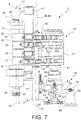
- the first half-shell 21 and the second half-shell 22 can thereby rotate around the hinge axis 23 between a configuration with the mould closed ( Fig.: 2 , 4 and 6 ) wherein the half-shells 21 and 22 are in contact along respective mould rims 24 and a configuration of mould open Fig.: 3 , 5 and 7 ).
- the half-shells 21 and 22 can therefore be opened/ closed like the two shells of bivalve shell.
- the half shells 21 and 22 are suitable for closing towards a closure plane X-X passing through the hinge axis 23, in particular the closure plane X-X also passing through the machine axis 2. This way each mould 2 can be opened towards the outside of the machine 1.
- the moulding unit 10 comprises a bottom 52 suitable for cooperating with the half-shells 21 and 22 and movement means 50 of the bottom, to cyclically form a closed cavity 24 suitable for receiving a pre-heated pre-form and for allowing the expansion by blowing or stretch blow moulding of the pre-form inside the cavity 24 to obtain a bottle or container.
- the half-shells 21 and 22 and the bottom 52 are actuated by means of opening/closing means 12 of the half-shells 21, 22 and movement means 50 of the bottom 52, in a synchronized manner starting from a single motion inlet 36 comprising a single cam coupling.
- the half-shells 21 and 22 rotate around the hinge axis 23 concurrently with a translation of said hinge axis 23 along the plane X-X in a direction substantially perpendicular to the hinge axis itself.
- the half shells 21 and 22 comprise a respective shaped portion which repeats in negative the outer shape of the bottle to be obtained from the preform and which delimits the space inside which the preform is made to expand, wherein such shaped portion is separable from the half shells 21 and 22 and interchangeable, so as to permit the moulding of bottles of different shapes and sizes. This way it is sufficient to substitute the shaped portions to start the production of different bottles.
- the aforesaid opening/closing means of the mould 20 comprise a throw having a rotation axis 26, integral with the blowing machine 1, positioned substantially parallel to the hinge axis 23, and an eccentric axis 27, parallel to the main axis 26 and distanced from the eccentric axis 27 by a pre-set arm value B.
- the main rotation axis 26 coincides with the axis of two cylindrical end sections 28 and 29 of the throw 25, so-called “bench pins", while the eccentric axis 27 coincides with a central cylindrical section 30, so-called “crank pin” positioned between the end sections 28 and 29.
- the crank pin 30 is rigidly connected to the bench pins 28 and 29 by arms 31 and 32.
- the opening/closing means comprise at least one connecting rod 33 having a first end 34 rotatably connected to said eccentric axis 27 and a second end 35 rotatably connected to said hinge axis 23.
- connecting rods 33 are envisaged having a first end 34 rotatably connected to said eccentric axis 27 and a second end 35 rotatably connected to said hinge axis 23.
- the opening/closing means of the mould 20 comprise at least a first crank 40 having a first end rotatably connected to a first fixed axis 37 integral with the machine 1, and a second end rotatably connected around a first axis 43 of the first half-shell 21 on the same side as the plane X-X relative to the first fixed axis 37.
- the opening/closing means of the mould 20 comprise at least a second crank 41 having a first end rotatably connected to a second fixed axis 38 integral with the machine 1 and a second end rotatably connected around a second axis 44 of the second half-shell 22 on the same side as the plane X-X relative to the second fixed axis 38.
- the opening/closing means comprise two first cranks 40 substantially equal and two second cranks 41 substantially equal.
- the fixed axes 37, 38 and/or the first side axis 43 and second side axis 44 are substantially parallel to one another and substantially parallel to the hinge axis 23.
- the first side axis 43 and the second side axis 44 are distanced on opposite sides relative to the closure plane X-X.
- the at least one first crank 40 and/or the at least one second crank 41 are arranged on a plane substantially orthogonal to the hinge axis 23.
- the at least one first crank 40 and/or the at least one second crank 41 are arranged transversally to the closure plane X-X.
- the fixed axes 37, 38 are distanced from the closure plane X-X by a value that is greater than the distance of the first side axis 43 and the second side axis 44 from the closure plane X-X.
- the first fixed axis 37 and the first side axis 43 are specularly arranged to the second fixed axis 38 and the second side axis 44 relative to the closure plane X-X.
- the rotation of the throw 25 around its main axis 26 obliges the eccentric axis 27 to rotate around the main axis 26 according to a radius equal to B.
- Such rotation drags the at least one connecting rod 33 so as to impart to the hinge axis 23 a reciprocating translation movement along the closure plane X-X between a closed position of the mould in which the eccentric axis 27 is aligned with the main axis 26 along the closure plane X-X and opposite the hinge axis 23 ( Fig.4 ), and an open position of the mould in which the eccentric axis 27 is aligned with the main axis 26 along the closure plane X-X on the same side as the hinge axis 23 ( Fig.5 ).
- the at least one connecting rod 33 co-operates with the at least one first crank 40 and/or the at least one second crank 41 forcing the two half-shells 21 and 22 to rotate in relation to the hinge axis 23 concurrently with the translation of the hinge axis thereby performing the opening or closing of the mould 20.
- Such embodiment of the opening/closing means of the mould 20 has the advantage that when the mould 20 is closed, the two half-shells 21 and 22 are pressed against each other as a combined effect of the compression force exerted by the at least one first crank 40 and the at least one second crank 41 and a driving force exerted by the at least one connecting rod 33, any further opening movement of the half shells 21 and 22 thereby being prevented.
- the at least one connecting rod 33 applies a force to the hinge axis 23 directed by the hinge axis 23 towards the main axis 26 of the throw 25 and concurrently each first crank 40 and second crank 41 applies, to the respective side axes 43 and 44, a respective force positioned along the line joining the fixed axis 37 and 38 and the side axis 43 and 44 and facing towards the closure plane X-X.
- Such forces have a normal component at the closure plane X-X and facing towards the closure plane X-X. This way the pressure exerted between the half shells 21 and 22 during blowing is offset by such normal components in synergy with the geometric non yielding nature of the half shells 21 and 22.
- opening /closing means make it possible to self-block the half shells when they are in a closed position to contrast the pressure exerted inside the cavity during the blowing into the preform to expand and obtain the bottle.
- This advantage makes it possible to prevent the need for the presence of locking means suitable for keeping the half shells 21 and 22 closed during blowing. Thereby it makes it possible to avoid the use of a bolt suitable for keeping the half-shells closed.
- a positive consequence of this advantage is the complete elimination of waiting time for inserting and extracting the bolt respectively before and after the blowing, with a reduction of the production times and increased production rate.
- the mould unit 10 is suitable for receiving the movement by means of a torque applied to the main axis 26, for example by means of a coupling with toothed wheels.
- a toothed wheel 36 coaxial with the main axis 26 is present.
- the mould unit 10 comprises motion inlet means suitable for taking the motion from a mated profile coupling and transmitting it to the throw 25 by applying a torque around the main axis 26.
- such motion inlet means comprise a rotation axis 70, a toothed wheel 71 suitable for rotating around the rotation axis 70 and suitable for meshing with the toothed wheel 36, a crank 72 integral with the toothed sector 71, having a rotation axis coinciding with the axis 70, a crank end having a projecting or driven pin 73, suitable for engaging slidingly on a shaped profile or cam, shaped so as to impart on the toothed sector 71 a rotation of a value suitable for making the toothed wheel 36 rotate by a predefined angle so as to complete an entire opening-closing cycle of the mould 20.
- such predefined angle to bring the mould 20 from the open to the closed configuration or vice versa is substantially equal to 180°.
- the half-shells 21 and 22 comprise a bottom aperture 51 corresponding to a bottom portion of the bottle to be obtained, said aperture being suitable for being closed alternatively by the aforementioned bottom 52, so that said aperture is closed by said bottom 52 when the half shells 21 and 22 are closed, and is open when the half-shells 21 and 22 are open.
- the aperture 51 is obtained in a direction parallel to the hinge axis 23 and is positioned in a lower area of the half shells 21 and 22.
- the mould unit 10 comprises automatic movement means 50 of the bottom 52, in particular suitable for translating the bottom in a direction parallel to the hinge axis 23 between a lower open position and an upper closed position.
- the mould unit 10 comprises a hinge pin 54 having an axis 23 coinciding with the hinge axis 23, said hinge pin extending beyond the half shells 21 and 22 on the side of the bottom aperture 51 and a bracket 53 slidingly connected to the hinge pin 54 in such a way as to be able translate along the hinge axis 23, such bracket 53 integrally supporting the bottom 52.
- the bracket 53 is connected to the hinge pin 54 by means of a sliding guide 55 parallel to the hinge axis 23 and integral with the hinge pin 54, and a saddle 56 integral with the bracket 53 and sliding on the guide 55.
- the movement means 50 of the bottom 52 comprise at least a pair of connecting rods 57 and 58 mounted in series and rotatably mutually connected around a common rotational axis 59, so that a first end of one connecting rod 57 is connected to a first end of the other connecting rod 58.
- Such connecting rods 57 and 58 are fitted interposed between the bracket 53 and a support arm 62 fixed to the hinge in 54 on the side opposite the bracket 53 in relation to the connecting rods 57 and 58, and have a second end connected so as to rotate in relation to the bracket 53 and the support arm 62.
- Such movement means further comprise an operation arm 63 having a first end rotatably connected to the connecting rods 57 and 58 around the common rotation axis 59, and a second end rotatably connected to a fixed axis 64 integral with the machine 1.
- the arm 63 is positioned in such way as to be able to rotate on the closure plane X-X around the fixed axis 64, which belongs to a support 65 integral with the machine 1.
- the translation movement of the hinge axis 23 along the closure plane X-X brings the hinge pin 54 into reciprocating translation motion between an open position and a closed position of the half-shells.
- the hinge pin 54 is in the open position of the moulds ( fig.7 ), therefore in the position furthest away from the main axis 26 of the throw 25, such hinge pin is in the position closest to the fixed axis 64 of the arm 63.
- the second ends of the connecting rods 57 and 58 are constrained to rotate towards each other around the common axis 59 causing the bracket 53 and the support arm 62 to move towards each other and thereby the distancing of the bottom 52 from the aperture 51.
- the hinge pin 54 When, instead, the hinge pin 54 is in the closed position of the moulds ( fig.6 ), the hinge pin 54 is in the position closest to the main axis 26 of the throw 25 and therefore in the position furthest away from the axis 64. In this configuration the second ends of the connecting rods 57 and 58 are constrained to rotate away from each other causing the distancing of the bracket from the support arm 62, and thereby the movement of the bottom 52 towards the aperture 51.
- the mould unit 10 comprises guide means suitable for constraining the movement of the hinge axis 23 to translation only in a direction orthogonal to said axis 23 and along the closure plane X-X.
- such means comprise a guide 66 substantially orthogonal to the hinge axis 23 and belonging to the closure plane X-X, integral with the machine 1, and a saddle 67 integral with the hinge axis 23 and sliding in such a guide 66.
- the saddle 67 is fixed to the support arm 62.
Landscapes
- Engineering & Computer Science (AREA)
- Manufacturing & Machinery (AREA)
- Mechanical Engineering (AREA)
- Moulds For Moulding Plastics Or The Like (AREA)
- Blow-Moulding Or Thermoforming Of Plastics Or The Like (AREA)
- Compositions Of Macromolecular Compounds (AREA)
- Manufacture Of Porous Articles, And Recovery And Treatment Of Waste Products (AREA)
Claims (12)
- Maschine (1) zum Blas- oder Streckblasformen von Polymermaterialflaschen oder -Behältern mit einer Mehrzahl von Formungseinheiten (10), wobei jede Formungseinheit (10) eine seitliche erste Halbschale (21) und eine zweite Halbschale (22), die um einen eine Gelenkachse (23) aufweisenden Gelenkbolzen (54) angelenkt sind, sowie einen Boden (52), der mit der ersten Halbschale (21) und der zweiten Halbschale (22) zusammenwirkt, aufweist, um zyklisch einen geschlossenen Hohlraum (24) zu bilden, der geeignet ist, um einen vorgewärmten Vorformling aufzunehmen und die Expansion durch das Blas- oder Streckblasformen des Vorformlings innerhalb des Hohlraums (24) zu erlauben, um eine Flasche oder einen Behälter zu erhalten, wobei die Formungseinheit (10) angeordnet ist, um zyklisch eine geschlossene Formkonfiguration und eine offene Formkonfiguration zu einer durch die Gelenkachse (23) hindurchgehenden Verschlussebene X-X hin und von dieser weg einzunehmen, wobei die Formungseinheit (10) Öffnungs-/Schließmittel (12) der Halbschalen (21, 22) und Handhabungsmittel (50) des Bodens (52) aufweist,
dadurch gekennzeichnet, dass:- die Halbschalen (21, 22) und der Boden (52), ausgehend von einem einzelnen Bewegungseinlass (36), der eine Einzelnocken-Kupplung aufweist, durch die Öffnungs-/Schließmittel (12) der Halbschalen (21, 22) und Handhabungsmittel (50) des Bodens (52) synchronisiert aktiviert werden;- wobei sich die Halbschalen (21, 22) um die Gelenkachse (23) gleichzeitig mit einer Translation der Gelenkachse (23) entlang der Ebene X-X in einer Richtung, die im Wesentlichen orthogonal zu der Gelenkachse (23) selbst ist, drehen. - Die Maschine nach Anspruch 1, wobei die Öffnungs-/Schließmittel (12) zumindest eine Verbindungsstange (33) aufweisen, die dazu geeignet ist, die Gelenkachse (23) entlang der Ebene X-X abwechselnd zwischen einer vorderen Position und einer hinteren Position zu verlagern, und wobei die Halbschalen (21, 22) durch Verbindungsmittel mit einer festen Lagerung (37, 38) beweglich verbunden sind, so dass die Halbschalen (21, 22) in der vorderen Position offen sind und in der hinteren Position geschlossen sind.
- Die Maschine nach Anspruch 2, wobei die Verbindungsmittel zumindest eine Kurbel (40, 41) aufweisen.
- Die Maschine nach zumindest einem der vorhergehenden Ansprüche, wobei die Öffnungs-/Schließmittel (12) dazu geeignet sind, durch Anwendung von Schließkräften, die in angenähert tangentialer Richtung in Bezug auf die Gelenkachse (23) konvergieren, die Halbschalen (21, 22) automatisch zu arretieren und gegeneinander zu pressen, wenn die Formungseinheit (10) in der geschlossenen Formkonfiguration ist.
- Die Maschine nach einem vorhergehenden Anspruch, wobei die Öffnungs-/Schließmittel (12) aufweisen:- einen Wurf (25) mit zumindest einem Hauptabschnitt (28, 29), der eine Drehachse (26) aufweist, die im Wesentlichen parallel zu der Gelenkachse (23) ist, sowie einem Exzenterabschnitt (30) mit einer Achse (27), die parallel zu der Hauptdrehachse (26) und mit einem voreingestellten Armwert B von der Exzenterachse (27) beabstandet ist;- zumindest eine Verbindungsstange (33) mit einem ersten Ende (34), das mit dem Exzenterabschnitt (30) drehbar verbunden ist, und einem zweiten Ende (35), das mit der Gelenkachse (23) drehbar verbunden ist,- zumindest eine erste Kurbel (40) mit einem ersten Ende, das mit einer ersten festen Achse (37) drehbar verbunden ist, die an die Maschine (10) integriert ist, sowie einem zweiten Ende, das um eine erste Seitenachse (43) der ersten Halbschale (21) an der gleichen Seite der Verschlussebene X-X in Bezug auf die erste feste Achse (37) drehbar verbunden ist;- zumindest eine zweite Kubel (41) mit einem ersten Ende, das mit einer zweiten festen Achse (38) drehbar verbunden ist, die an die Maschine (1) integriert ist, sowie einem zweiten Ende, das um eine zweite Seitenachse (44) der zweiten Halbschale (22) an der gleichen Seite der Verschlussebene X-X in Bezug auf die zweite feste Achse (38) drehbar verbunden ist;wobei in der geschlossenen Formkonfiguration die Exzenterachse (27) mit der Hauptachse (26) entlang der Verschlussebene X-X und an der entgegengesetzten Seite relativ zu der Gelenkachse (23) in Bezug auf die Hauptachse (26) ausgerichtet ist, und in der offenen Formkonfiguration die Exzenterachse (27) mit der Hauptachse (26) entlang der Verschlussebene X-X, und zwischen der Hauptachse (26) und der Gelenkachse (23) aufgenommen, ausgerichtet ist.
- Die Maschine nach Anspruch 5, wobei die festen Achsen (37, 38) und die erste Seitenachse (43) und die zweite Seitenachse (44) im Wesentlichen parallel zueinander und im Wesentlichen parallel zur Gelenkachse (23) sind.
- Die Maschine nach Anspruch 5 oder 6, wobei die zumindest eine erste Kurbel (40) und/oder die zumindest eine zweite Kurbel (41) relativ zur Verschlussebene X-X transversal angeordnet sind, und/oder wobei die ersten und zweiten festen Achsen (37, 38) von der Verschlussebene X-X um einen Wert beabstandet sind, der größer ist als der Abstand der ersten und Seitenachsen (43, 44) von der Verschlussebene X-X, und/oder wobei die ersten und zweiten festen Achsen (37, 38) zwischen den Seitenachsen (43, 44) und der Hauptachse (26) eingefügt sind.
- Die Maschine nach einem der Ansprüche 5 bis 7, wobei die erste feste Achse (37) und die Seitenachse (43) relativ zu der Verschlussebene X-X spiegelbildlich zu der zweiten festen Achse (38) und der zweiten Seitenachse (44) angeordnet sind.
- Die Maschine nach einem vorhergehenden Anspruch, die Führungsmittel aufweist, die geeignet sind, die Translation der Gelenkachse (23) nur in einer Richtung, die orthogonal zu der Gelenkachse (23) ist, und entlang der Verschlussebene X-X zu erlauben.
- Die Maschine nach Anspruch 9, wobei die Führungsmittel eine Führung (66) aufweisen, die im Wesentlichen orthogonal zu der Gelenkachse (23) ist, die an die Maschine (1) integriert ist und zu der Verschlussebene X-X gehört, und einen Sattel (67), der an die Gelenkachse (23) integriert ist und in dieser Führung (66) gleitet.
- Die Maschine nach einem vorhergehenden Anspruch, wobei die Bodenhandhabungsmittel (50) aufweisen:- Gleiteingriffsmittel (55, 56) des Bodens (52) zu dem Gelenkbolzen (24), die eine Annäherungs- oder Wegbewegung des Bodens (52) zu/von den Halbschalen (21, 22) erlauben;- zumindest ein Paar von Verbindungsstangen (57, 58), die in Serie angebracht und um eine gemeinsame Drehachse (59) miteinander drehbar verbunden sind, so dass ein erstes Ende einer kleinen Verbindungsstange (57) mit einem ersten Ende der anderen Verbindungsstange (58) verbunden ist und deren jeweiliges zweites Ende mit dem Boden (52) beziehungsweise mit einem Tragarm (62) verbunden ist, der an dem Gelenkbolzen (54) transversal integriert befestigt ist, wobei das Paar von kleinen Verbindungsstangen (57, 58) zwischen dem Boden (53) und dem Tragarm (62) aufgenommen ist;- einen Betätigungsarm (63), der ein erstes Ende aufweist, das mit den ersten Enden der kleinen Verbindungsstangen um die gemeinsame Achse (59) herum drehbar verbunden ist, sowie ein zweites Ende, das mit einer festen Achse (64) drehbar verbunden ist, die an die Maschine (1) integriert ist,wobei die Annäherungs- oder Wegbewegung des Bodens (52) durch die Translationsbewegung des Gelenkbolzens (54) direkt aktiviert wird.
- Die Maschine nach einem vorhergehenden Anspruch, wobei jede der Formungseinheiten (10) Bewegungseinlassmittel (16) aufweist, welche aufweisen:- einen Zahnsektor (71) mit einer festen Drehachse (70), der and die Maschine (1) integriert ist, geeignet zur Verzahnung mit einem Zahnrad (36), das integriert zu und koaxial mit einem Hauptabschnitt (2) des Wurfs (25) ist;- eine Kurbel (72), die an den Zahnsektor (71) integriert ist, und ein erstes Ende aufweist, das mit dem Zahnsektor (71) entlang der Achse (70) des Sektors starr verbunden ist, sowie ein zweites Ende, das einen vorstehenden Stift (73) aufweist, der zum Gleiteingriff entlang eines geformten Führungsnockens geeignet ist.
Priority Applications (1)
| Application Number | Priority Date | Filing Date | Title |
|---|---|---|---|
| PL12191388T PL2591905T3 (pl) | 2011-11-09 | 2012-11-06 | Maszyna do rozdmuchiwania albo do formowania z rozciąganiem i rozdmuchiwaniem butelek z materiału polimerowego |
Applications Claiming Priority (1)
| Application Number | Priority Date | Filing Date | Title |
|---|---|---|---|
| IT002033A ITMI20112033A1 (it) | 2011-11-09 | 2011-11-09 | Macchina per la soffiatura o stiro-soffiatura di bottiglie in materiale polimerico |
Publications (2)
| Publication Number | Publication Date |
|---|---|
| EP2591905A1 EP2591905A1 (de) | 2013-05-15 |
| EP2591905B1 true EP2591905B1 (de) | 2019-04-24 |
Family
ID=45571650
Family Applications (1)
| Application Number | Title | Priority Date | Filing Date |
|---|---|---|---|
| EP12191388.3A Active EP2591905B1 (de) | 2011-11-09 | 2012-11-06 | Maschine zum Blasen oder Streckblasen von Flaschen aus Polymermaterial |
Country Status (8)
| Country | Link |
|---|---|
| US (1) | US8905750B2 (de) |
| EP (1) | EP2591905B1 (de) |
| CN (1) | CN103101184B (de) |
| CA (1) | CA2794803C (de) |
| ES (1) | ES2736255T3 (de) |
| IT (1) | ITMI20112033A1 (de) |
| PL (1) | PL2591905T3 (de) |
| TR (1) | TR201910709T4 (de) |
Families Citing this family (11)
| Publication number | Priority date | Publication date | Assignee | Title |
|---|---|---|---|---|
| ITMI20120397A1 (it) | 2012-03-14 | 2013-09-15 | Smi Spa | Sistema di manipolazione di oggetti in macchine rotative |
| CN103171141B (zh) | 2013-03-19 | 2015-08-26 | 江苏新美星包装机械股份有限公司 | 一种底模的升降机构 |
| CN103692642B (zh) * | 2013-12-23 | 2016-01-20 | 冯伟君 | 吹塑机的模架结构 |
| CN103847090B (zh) * | 2014-03-18 | 2015-12-30 | 江苏星A包装机械集团有限公司 | 无菌吹灌旋生产线中的模具开合驱动装置 |
| CN107107450B (zh) * | 2014-10-01 | 2019-11-12 | S.I.P.A.工业设计自动化合伙股份有限公司 | 用于热塑性材料容器的模制设备 |
| CA2989274C (en) * | 2015-06-15 | 2023-10-17 | S.I.P.A. Societa' Industrializzazione Progettazione E Automazione S.P.A. | A blowing mold for blowing thermoplastic material containers |
| DE102015117017A1 (de) | 2015-10-06 | 2017-04-06 | Krones Ag | Vorrichtung und Verfahren zum Umformen von Kunststoffvorformlingen zu Kunststoffbehältnissen mit Kopplungseinrichtung |
| DE102016006211A1 (de) | 2016-05-19 | 2017-11-23 | Khs Corpoplast Gmbh | Formträger zur Aufnahme einer Form zur Formung von Hohlkörpern aus Vorformlingen |
| CN107962762B (zh) * | 2017-12-01 | 2020-04-14 | 江苏新美星包装机械股份有限公司 | 一种吹瓶机开合模模架与底模模架的联动装置 |
| FR3131243B1 (fr) * | 2021-12-29 | 2024-09-13 | Sidel Participations | Dispositif de moulage, par soufflage ou étirage-soufflage, de récipients en matière thermoplastique |
| CN115503218B (zh) * | 2022-09-26 | 2024-05-03 | 江苏新美星包装机械股份有限公司 | 一种单开模吹瓶模架 |
Family Cites Families (10)
| Publication number | Priority date | Publication date | Assignee | Title |
|---|---|---|---|---|
| US2290129A (en) * | 1938-09-07 | 1942-07-14 | Owens Illinois Glass Co | Apparatus for molding plastics |
| FR1559785A (de) * | 1968-01-16 | 1969-03-14 | ||
| US3632261A (en) * | 1969-09-22 | 1972-01-04 | Midland Ross Corp | Continuous-parison blow-molding machine |
| US4141680A (en) * | 1973-11-14 | 1979-02-27 | Monsanto Company | Rotary stretch blow molding apparatus |
| DE3729451C1 (de) * | 1987-09-03 | 1988-06-16 | Berstorff Gmbh Masch Hermann | Einrichtung zum exakten und schnellen OEffnen sowie Schliessen der beiden Formhaelften einer Blasform |
| FR2793722B1 (fr) * | 1999-05-17 | 2001-08-03 | Sidel Sa | Machine de soufflage comportant un mecanisme de fermeture et de verrouillage combines d'une unite de moulage |
| FR2825659B1 (fr) * | 2001-06-08 | 2003-09-19 | Ads | Systeme d'actionnement d'un moule en deux parties formant deux demi-moules articules entre eux |
| FR2888154B1 (fr) * | 2005-07-11 | 2007-11-16 | Sidel Sas | Unites de moulage et machine de moulage a pas vaviable |
| EP1995038A1 (de) * | 2007-05-22 | 2008-11-26 | TecPET innovation GmbH | Spritzblasvorrichtung |
| CN201872329U (zh) * | 2010-11-05 | 2011-06-22 | 铨宝工业股份有限公司 | 连杆式开关模装置 |
-
2011
- 2011-11-09 IT IT002033A patent/ITMI20112033A1/it unknown
-
2012
- 2012-11-06 TR TR2019/10709T patent/TR201910709T4/tr unknown
- 2012-11-06 PL PL12191388T patent/PL2591905T3/pl unknown
- 2012-11-06 ES ES12191388T patent/ES2736255T3/es active Active
- 2012-11-06 EP EP12191388.3A patent/EP2591905B1/de active Active
- 2012-11-06 CA CA2794803A patent/CA2794803C/en active Active
- 2012-11-08 US US13/671,596 patent/US8905750B2/en active Active
- 2012-11-09 CN CN201210448713.5A patent/CN103101184B/zh active Active
Non-Patent Citations (1)
| Title |
|---|
| None * |
Also Published As
| Publication number | Publication date |
|---|---|
| TR201910709T4 (tr) | 2019-08-21 |
| PL2591905T3 (pl) | 2019-11-29 |
| US8905750B2 (en) | 2014-12-09 |
| ES2736255T3 (es) | 2019-12-27 |
| CA2794803C (en) | 2020-03-31 |
| US20130115326A1 (en) | 2013-05-09 |
| ITMI20112033A1 (it) | 2013-05-10 |
| EP2591905A1 (de) | 2013-05-15 |
| CN103101184B (zh) | 2016-12-21 |
| CN103101184A (zh) | 2013-05-15 |
| CA2794803A1 (en) | 2013-05-09 |
Similar Documents
| Publication | Publication Date | Title |
|---|---|---|
| CA2794803C (en) | Machine for the blowing or stretch blow moulding of bottles in polymeric material | |
| US7543697B2 (en) | Rotary device for transferring containers | |
| EP2639189B1 (de) | Behandlungseinheit, Blasformvorrichtung mit einer solchen Einheit und Rotationsmaschine mit mehreren von solchen Einheiten | |
| EP2335903A1 (de) | Karussellblasformmaschine | |
| EP3103615B1 (de) | Blas- oder streckblasmaschine für flaschen aus polymermaterial | |
| CN1144666C (zh) | 生产热塑性材料挤压成形模模体的装置的改进 | |
| US8029270B2 (en) | Method and device for blow-molding containers | |
| US8465274B2 (en) | Moulding unit for a plant for blow-moulding plastic containers, particularly bottles | |
| CN111216340B (zh) | 一种把手瓶自动吹瓶系统及其方法 | |
| AU716736B2 (en) | Device for molding thermoplastic containers and container manufacturing plant making use thereof. | |
| NO309028B1 (no) | Apparat for fremstilling av hule gjenstander, særlig plastemner | |
| ITBO20080473A1 (it) | Unita' di formatura di un impianto per il soffiaggio di contenitori di plastica, in particolare bottiglie | |
| US8431069B2 (en) | Mould for moulding a container obtained from a parison of plastic material and method thereof | |
| EP2942179B1 (de) | Maschine zum blasformen oder dehnen oder dehn-blasformen von flaschen in einem polymermaterial | |
| US7914276B2 (en) | Variable-pitch moulding units and moulding machine | |
| JP6594848B2 (ja) | 処理システム及び処理方法 | |
| EP1386712A1 (de) | Werkzeug zur Herstellung von Kunststoffstopfen mit durch Scharnier angelenkten Deckeln | |
| WO2018178774A2 (en) | Device for the production of plastic containers | |
| US20090121388A1 (en) | Unit and Method for Compression Moulding Polymeric Articles | |
| EP1901904B1 (de) | Formpressmaschine | |
| CN118488889A (zh) | 通过吹制或拉制吹制模制热塑性材料制容器的模制装置 |
Legal Events
| Date | Code | Title | Description |
|---|---|---|---|
| PUAI | Public reference made under article 153(3) epc to a published international application that has entered the european phase |
Free format text: ORIGINAL CODE: 0009012 |
|
| AK | Designated contracting states |
Kind code of ref document: A1 Designated state(s): AL AT BE BG CH CY CZ DE DK EE ES FI FR GB GR HR HU IE IS IT LI LT LU LV MC MK MT NL NO PL PT RO RS SE SI SK SM TR |
|
| AX | Request for extension of the european patent |
Extension state: BA ME |
|
| 17P | Request for examination filed |
Effective date: 20130523 |
|
| RAX | Requested extension states of the european patent have changed |
Extension state: BA Payment date: 20130523 Extension state: ME Payment date: 20130523 |
|
| RBV | Designated contracting states (corrected) |
Designated state(s): AL AT BE BG CH CY CZ DE DK EE ES FI FR GB GR HR HU IE IS IT LI LT LU LV MC MK MT NL NO PL PT RO RS SE SI SK SM TR |
|
| GRAP | Despatch of communication of intention to grant a patent |
Free format text: ORIGINAL CODE: EPIDOSNIGR1 |
|
| STAA | Information on the status of an ep patent application or granted ep patent |
Free format text: STATUS: GRANT OF PATENT IS INTENDED |
|
| INTG | Intention to grant announced |
Effective date: 20190125 |
|
| RAX | Requested extension states of the european patent have changed |
Extension state: ME Payment date: 20130621 Extension state: BA Payment date: 20130621 |
|
| GRAS | Grant fee paid |
Free format text: ORIGINAL CODE: EPIDOSNIGR3 |
|
| GRAA | (expected) grant |
Free format text: ORIGINAL CODE: 0009210 |
|
| STAA | Information on the status of an ep patent application or granted ep patent |
Free format text: STATUS: THE PATENT HAS BEEN GRANTED |
|
| AK | Designated contracting states |
Kind code of ref document: B1 Designated state(s): AL AT BE BG CH CY CZ DE DK EE ES FI FR GB GR HR HU IE IS IT LI LT LU LV MC MK MT NL NO PL PT RO RS SE SI SK SM TR |
|
| AX | Request for extension of the european patent |
Extension state: BA ME |
|
| REG | Reference to a national code |
Ref country code: GB Ref legal event code: FG4D |
|
| REG | Reference to a national code |
Ref country code: CH Ref legal event code: EP |
|
| REG | Reference to a national code |
Ref country code: AT Ref legal event code: REF Ref document number: 1123619 Country of ref document: AT Kind code of ref document: T Effective date: 20190515 Ref country code: IE Ref legal event code: FG4D |
|
| REG | Reference to a national code |
Ref country code: DE Ref legal event code: R096 Ref document number: 602012059287 Country of ref document: DE |
|
| REG | Reference to a national code |
Ref country code: NL Ref legal event code: MP Effective date: 20190424 |
|
| REG | Reference to a national code |
Ref country code: LT Ref legal event code: MG4D |
|
| PG25 | Lapsed in a contracting state [announced via postgrant information from national office to epo] |
Ref country code: NL Free format text: LAPSE BECAUSE OF FAILURE TO SUBMIT A TRANSLATION OF THE DESCRIPTION OR TO PAY THE FEE WITHIN THE PRESCRIBED TIME-LIMIT Effective date: 20190424 |
|
| PG25 | Lapsed in a contracting state [announced via postgrant information from national office to epo] |
Ref country code: FI Free format text: LAPSE BECAUSE OF FAILURE TO SUBMIT A TRANSLATION OF THE DESCRIPTION OR TO PAY THE FEE WITHIN THE PRESCRIBED TIME-LIMIT Effective date: 20190424 Ref country code: NO Free format text: LAPSE BECAUSE OF FAILURE TO SUBMIT A TRANSLATION OF THE DESCRIPTION OR TO PAY THE FEE WITHIN THE PRESCRIBED TIME-LIMIT Effective date: 20190724 Ref country code: HR Free format text: LAPSE BECAUSE OF FAILURE TO SUBMIT A TRANSLATION OF THE DESCRIPTION OR TO PAY THE FEE WITHIN THE PRESCRIBED TIME-LIMIT Effective date: 20190424 Ref country code: LT Free format text: LAPSE BECAUSE OF FAILURE TO SUBMIT A TRANSLATION OF THE DESCRIPTION OR TO PAY THE FEE WITHIN THE PRESCRIBED TIME-LIMIT Effective date: 20190424 Ref country code: AL Free format text: LAPSE BECAUSE OF FAILURE TO SUBMIT A TRANSLATION OF THE DESCRIPTION OR TO PAY THE FEE WITHIN THE PRESCRIBED TIME-LIMIT Effective date: 20190424 Ref country code: PT Free format text: LAPSE BECAUSE OF FAILURE TO SUBMIT A TRANSLATION OF THE DESCRIPTION OR TO PAY THE FEE WITHIN THE PRESCRIBED TIME-LIMIT Effective date: 20190824 Ref country code: SE Free format text: LAPSE BECAUSE OF FAILURE TO SUBMIT A TRANSLATION OF THE DESCRIPTION OR TO PAY THE FEE WITHIN THE PRESCRIBED TIME-LIMIT Effective date: 20190424 |
|
| PG25 | Lapsed in a contracting state [announced via postgrant information from national office to epo] |
Ref country code: BG Free format text: LAPSE BECAUSE OF FAILURE TO SUBMIT A TRANSLATION OF THE DESCRIPTION OR TO PAY THE FEE WITHIN THE PRESCRIBED TIME-LIMIT Effective date: 20190724 Ref country code: GR Free format text: LAPSE BECAUSE OF FAILURE TO SUBMIT A TRANSLATION OF THE DESCRIPTION OR TO PAY THE FEE WITHIN THE PRESCRIBED TIME-LIMIT Effective date: 20190725 Ref country code: LV Free format text: LAPSE BECAUSE OF FAILURE TO SUBMIT A TRANSLATION OF THE DESCRIPTION OR TO PAY THE FEE WITHIN THE PRESCRIBED TIME-LIMIT Effective date: 20190424 Ref country code: RS Free format text: LAPSE BECAUSE OF FAILURE TO SUBMIT A TRANSLATION OF THE DESCRIPTION OR TO PAY THE FEE WITHIN THE PRESCRIBED TIME-LIMIT Effective date: 20190424 |
|
| REG | Reference to a national code |
Ref country code: ES Ref legal event code: FG2A Ref document number: 2736255 Country of ref document: ES Kind code of ref document: T3 Effective date: 20191227 |
|
| PG25 | Lapsed in a contracting state [announced via postgrant information from national office to epo] |
Ref country code: IS Free format text: LAPSE BECAUSE OF FAILURE TO SUBMIT A TRANSLATION OF THE DESCRIPTION OR TO PAY THE FEE WITHIN THE PRESCRIBED TIME-LIMIT Effective date: 20190824 |
|
| REG | Reference to a national code |
Ref country code: DE Ref legal event code: R097 Ref document number: 602012059287 Country of ref document: DE |
|
| PG25 | Lapsed in a contracting state [announced via postgrant information from national office to epo] |
Ref country code: SK Free format text: LAPSE BECAUSE OF FAILURE TO SUBMIT A TRANSLATION OF THE DESCRIPTION OR TO PAY THE FEE WITHIN THE PRESCRIBED TIME-LIMIT Effective date: 20190424 Ref country code: RO Free format text: LAPSE BECAUSE OF FAILURE TO SUBMIT A TRANSLATION OF THE DESCRIPTION OR TO PAY THE FEE WITHIN THE PRESCRIBED TIME-LIMIT Effective date: 20190424 Ref country code: CZ Free format text: LAPSE BECAUSE OF FAILURE TO SUBMIT A TRANSLATION OF THE DESCRIPTION OR TO PAY THE FEE WITHIN THE PRESCRIBED TIME-LIMIT Effective date: 20190424 Ref country code: DK Free format text: LAPSE BECAUSE OF FAILURE TO SUBMIT A TRANSLATION OF THE DESCRIPTION OR TO PAY THE FEE WITHIN THE PRESCRIBED TIME-LIMIT Effective date: 20190424 Ref country code: EE Free format text: LAPSE BECAUSE OF FAILURE TO SUBMIT A TRANSLATION OF THE DESCRIPTION OR TO PAY THE FEE WITHIN THE PRESCRIBED TIME-LIMIT Effective date: 20190424 |
|
| PG25 | Lapsed in a contracting state [announced via postgrant information from national office to epo] |
Ref country code: SM Free format text: LAPSE BECAUSE OF FAILURE TO SUBMIT A TRANSLATION OF THE DESCRIPTION OR TO PAY THE FEE WITHIN THE PRESCRIBED TIME-LIMIT Effective date: 20190424 |
|
| PLBE | No opposition filed within time limit |
Free format text: ORIGINAL CODE: 0009261 |
|
| STAA | Information on the status of an ep patent application or granted ep patent |
Free format text: STATUS: NO OPPOSITION FILED WITHIN TIME LIMIT |
|
| 26N | No opposition filed |
Effective date: 20200127 |
|
| PG25 | Lapsed in a contracting state [announced via postgrant information from national office to epo] |
Ref country code: SI Free format text: LAPSE BECAUSE OF FAILURE TO SUBMIT A TRANSLATION OF THE DESCRIPTION OR TO PAY THE FEE WITHIN THE PRESCRIBED TIME-LIMIT Effective date: 20190424 |
|
| REG | Reference to a national code |
Ref country code: CH Ref legal event code: PL |
|
| PG25 | Lapsed in a contracting state [announced via postgrant information from national office to epo] |
Ref country code: LU Free format text: LAPSE BECAUSE OF NON-PAYMENT OF DUE FEES Effective date: 20191106 Ref country code: CH Free format text: LAPSE BECAUSE OF NON-PAYMENT OF DUE FEES Effective date: 20191130 Ref country code: MC Free format text: LAPSE BECAUSE OF FAILURE TO SUBMIT A TRANSLATION OF THE DESCRIPTION OR TO PAY THE FEE WITHIN THE PRESCRIBED TIME-LIMIT Effective date: 20190424 Ref country code: LI Free format text: LAPSE BECAUSE OF NON-PAYMENT OF DUE FEES Effective date: 20191130 |
|
| REG | Reference to a national code |
Ref country code: BE Ref legal event code: MM Effective date: 20191130 |
|
| PG25 | Lapsed in a contracting state [announced via postgrant information from national office to epo] |
Ref country code: IE Free format text: LAPSE BECAUSE OF NON-PAYMENT OF DUE FEES Effective date: 20191106 |
|
| PG25 | Lapsed in a contracting state [announced via postgrant information from national office to epo] |
Ref country code: BE Free format text: LAPSE BECAUSE OF NON-PAYMENT OF DUE FEES Effective date: 20191130 |
|
| PG25 | Lapsed in a contracting state [announced via postgrant information from national office to epo] |
Ref country code: CY Free format text: LAPSE BECAUSE OF FAILURE TO SUBMIT A TRANSLATION OF THE DESCRIPTION OR TO PAY THE FEE WITHIN THE PRESCRIBED TIME-LIMIT Effective date: 20190424 |
|
| PG25 | Lapsed in a contracting state [announced via postgrant information from national office to epo] |
Ref country code: MT Free format text: LAPSE BECAUSE OF FAILURE TO SUBMIT A TRANSLATION OF THE DESCRIPTION OR TO PAY THE FEE WITHIN THE PRESCRIBED TIME-LIMIT Effective date: 20190424 Ref country code: HU Free format text: LAPSE BECAUSE OF FAILURE TO SUBMIT A TRANSLATION OF THE DESCRIPTION OR TO PAY THE FEE WITHIN THE PRESCRIBED TIME-LIMIT; INVALID AB INITIO Effective date: 20121106 |
|
| REG | Reference to a national code |
Ref country code: AT Ref legal event code: UEP Ref document number: 1123619 Country of ref document: AT Kind code of ref document: T Effective date: 20190424 |
|
| PG25 | Lapsed in a contracting state [announced via postgrant information from national office to epo] |
Ref country code: MK Free format text: LAPSE BECAUSE OF FAILURE TO SUBMIT A TRANSLATION OF THE DESCRIPTION OR TO PAY THE FEE WITHIN THE PRESCRIBED TIME-LIMIT Effective date: 20190424 |
|
| PGFP | Annual fee paid to national office [announced via postgrant information from national office to epo] |
Ref country code: IT Payment date: 20250908 Year of fee payment: 14 |
|
| PGFP | Annual fee paid to national office [announced via postgrant information from national office to epo] |
Ref country code: DE Payment date: 20251125 Year of fee payment: 14 |
|
| PGFP | Annual fee paid to national office [announced via postgrant information from national office to epo] |
Ref country code: GB Payment date: 20251121 Year of fee payment: 14 |
|
| PGFP | Annual fee paid to national office [announced via postgrant information from national office to epo] |
Ref country code: AT Payment date: 20250930 Year of fee payment: 14 |
|
| PGFP | Annual fee paid to national office [announced via postgrant information from national office to epo] |
Ref country code: FR Payment date: 20251107 Year of fee payment: 14 |
|
| PGFP | Annual fee paid to national office [announced via postgrant information from national office to epo] |
Ref country code: TR Payment date: 20251103 Year of fee payment: 14 |
|
| PGFP | Annual fee paid to national office [announced via postgrant information from national office to epo] |
Ref country code: PL Payment date: 20251021 Year of fee payment: 14 |
|
| PGFP | Annual fee paid to national office [announced via postgrant information from national office to epo] |
Ref country code: ES Payment date: 20251201 Year of fee payment: 14 |