EP2591670B1 - Fishing-reel reel unit and fishing reel - Google Patents
Fishing-reel reel unit and fishing reel Download PDFInfo
- Publication number
- EP2591670B1 EP2591670B1 EP12191198.6A EP12191198A EP2591670B1 EP 2591670 B1 EP2591670 B1 EP 2591670B1 EP 12191198 A EP12191198 A EP 12191198A EP 2591670 B1 EP2591670 B1 EP 2591670B1
- Authority
- EP
- European Patent Office
- Prior art keywords
- reel
- fishing
- outer member
- corrosion
- reel unit
- Prior art date
- Legal status (The legal status is an assumption and is not a legal conclusion. Google has not performed a legal analysis and makes no representation as to the accuracy of the status listed.)
- Active
Links
- 238000005260 corrosion Methods 0.000 claims description 51
- 230000007797 corrosion Effects 0.000 claims description 51
- 230000002093 peripheral effect Effects 0.000 claims description 41
- 238000000576 coating method Methods 0.000 claims description 38
- 239000011248 coating agent Substances 0.000 claims description 36
- 239000000463 material Substances 0.000 claims description 13
- 229910045601 alloy Inorganic materials 0.000 claims description 10
- 239000000956 alloy Substances 0.000 claims description 10
- 229910052751 metal Inorganic materials 0.000 claims description 7
- 239000002184 metal Substances 0.000 claims description 7
- 230000007246 mechanism Effects 0.000 description 23
- 230000009977 dual effect Effects 0.000 description 8
- 229910000838 Al alloy Inorganic materials 0.000 description 7
- 238000005520 cutting process Methods 0.000 description 7
- 238000003754 machining Methods 0.000 description 6
- 238000000034 method Methods 0.000 description 6
- 238000004804 winding Methods 0.000 description 6
- 238000005266 casting Methods 0.000 description 5
- 238000010168 coupling process Methods 0.000 description 5
- VYZAMTAEIAYCRO-UHFFFAOYSA-N Chromium Chemical compound [Cr] VYZAMTAEIAYCRO-UHFFFAOYSA-N 0.000 description 4
- 229910052804 chromium Inorganic materials 0.000 description 4
- 239000011651 chromium Substances 0.000 description 4
- 230000008878 coupling Effects 0.000 description 4
- 238000005859 coupling reaction Methods 0.000 description 4
- 238000000465 moulding Methods 0.000 description 4
- 238000007747 plating Methods 0.000 description 4
- 210000003813 thumb Anatomy 0.000 description 4
- 229910000861 Mg alloy Inorganic materials 0.000 description 3
- 230000000149 penetrating effect Effects 0.000 description 2
- 238000009987 spinning Methods 0.000 description 2
- 230000008901 benefit Effects 0.000 description 1
- 239000000919 ceramic Substances 0.000 description 1
- 238000010586 diagram Methods 0.000 description 1
- 230000000694 effects Effects 0.000 description 1
- 239000004519 grease Substances 0.000 description 1
- 230000002401 inhibitory effect Effects 0.000 description 1
- 238000004519 manufacturing process Methods 0.000 description 1
- 230000000873 masking effect Effects 0.000 description 1
- 239000007769 metal material Substances 0.000 description 1
- 229920001296 polysiloxane Polymers 0.000 description 1
- 230000008569 process Effects 0.000 description 1
- 230000001105 regulatory effect Effects 0.000 description 1
- 229920003002 synthetic resin Polymers 0.000 description 1
- 239000000057 synthetic resin Substances 0.000 description 1
- 238000003466 welding Methods 0.000 description 1
Images


Classifications
-
- A—HUMAN NECESSITIES
- A01—AGRICULTURE; FORESTRY; ANIMAL HUSBANDRY; HUNTING; TRAPPING; FISHING
- A01K—ANIMAL HUSBANDRY; CARE OF BIRDS, FISHES, INSECTS; FISHING; REARING OR BREEDING ANIMALS, NOT OTHERWISE PROVIDED FOR; NEW BREEDS OF ANIMALS
- A01K89/00—Reels
- A01K89/015—Reels with a rotary drum, i.e. with a rotating spool
- A01K89/0183—Drive mechanism details
- A01K89/0186—Drive mechanism details with disengageable positive drive components, e.g. a clutch
-
- A—HUMAN NECESSITIES
- A01—AGRICULTURE; FORESTRY; ANIMAL HUSBANDRY; HUNTING; TRAPPING; FISHING
- A01K—ANIMAL HUSBANDRY; CARE OF BIRDS, FISHES, INSECTS; FISHING; REARING OR BREEDING ANIMALS, NOT OTHERWISE PROVIDED FOR; NEW BREEDS OF ANIMALS
- A01K89/00—Reels
- A01K89/01—Reels with pick-up, i.e. with the guiding member rotating and the spool not rotating during normal retrieval of the line
-
- A—HUMAN NECESSITIES
- A01—AGRICULTURE; FORESTRY; ANIMAL HUSBANDRY; HUNTING; TRAPPING; FISHING
- A01K—ANIMAL HUSBANDRY; CARE OF BIRDS, FISHES, INSECTS; FISHING; REARING OR BREEDING ANIMALS, NOT OTHERWISE PROVIDED FOR; NEW BREEDS OF ANIMALS
- A01K89/00—Reels
-
- A—HUMAN NECESSITIES
- A01—AGRICULTURE; FORESTRY; ANIMAL HUSBANDRY; HUNTING; TRAPPING; FISHING
- A01K—ANIMAL HUSBANDRY; CARE OF BIRDS, FISHES, INSECTS; FISHING; REARING OR BREEDING ANIMALS, NOT OTHERWISE PROVIDED FOR; NEW BREEDS OF ANIMALS
- A01K89/00—Reels
- A01K89/015—Reels with a rotary drum, i.e. with a rotating spool
- A01K89/0155—Antibacklash devices
Description
- The present invention relates to a fishing-reel reel unit, and particularly to, a fishing-reel reel unit including a main body member.
- Fishing reels, which are attached to a fishing rod for winding and releasing a fishing line, are mainly classified into spinning reels and dual-bearing reels. A fishing reel of these types normally includes a reel unit, a handle shaft and a handle assembly. The reel unit is attached to the fishing rod. The handle shaft is rotatably supported by the reel unit. The handle assembly is fixed onto a tip of the handle shaft. The handle shaft thus structured is rotatably supported by the reel unit through a bearing mounted to the inner periphery of an opening formed by machining the reel unit made of metal (see e.g., Japan Patent No.
3066990 - In the aforementioned well-known fishing reels, it is required to highly accurately produce an inter-gear clearance (also referred to as "backlash") in reducing modules of gears (e.g., a drive gear and a pinion gear) that serve to transmit rotation of the handle shaft. To highly accurately produce the inter-gear clearance, it is required to highly accurately dispose the handle shaft to which the drive gear is fixed and a spool shaft to which the pinion gear is mounted. Further, to highly accurately dispose the handle shaft and the spool shaft, it is required to highly accurately form the inner peripheries of bearing mounting parts to which bearings are respectively mounted for supporting the handle shaft and the spool shaft.
- Incidentally, fishing reels are often used outdoors and have chances of having reel units exposed to corrosion atmosphere. In view of this, a corrosion-resistant coating is often formed on the reel unit. However, in forming such a corrosion-resistant coating on a bearing mounting part, the corrosion-resistant coating is also disposed on the inner periphery of the bearing mounting part. This degrades forming accuracy of the inner periphery of the bearing mounting part. Therefore, it is required to execute a work of exfoliating the corrosion-resistant coating formed on the inner periphery of the bearing mounting part and machining the inner periphery of the bearing mounting part in order to enhance forming accuracy of the inner periphery of the bearing mounting part. Therefore, it is remarkably difficult to keep corrosion resistance of the bearing mounting part high, and simultaneously, highly accurately form the inner periphery of the bearing mounting part. Document
EP 0924318 discloses a fishing-reel reel unit according to the preamble of claim 1. - It is an advantage of the present invention to highly accurately keep corrosion-resistance of a bearing mounting part high, and simultaneously, highly accurately form the inner periphery of the bearing mounting part in a fishing-reel reel unit.
- A fishing-reel reel unit includes a main body member; a first outer member, and a first inner member. The first outer member is mounted on the main body member, and the first outer member includes a corrosion-resistant coating formed thereon. The first inner member is formed in a tubular shape, when the first inner member is fixed to an inner periphery of the first outer member. The first inner member has a first inner peripheral surface on which a first bearing is mounted, and the first inner member is made of a corrosion-resistant material.
- According to a preferred embodiment of the fishing-reel reel unit of the present invention, the first outer member has a corrosion-resistant coating formed thereon, while the first inner member is made of a corrosion-resistant material and is fixed as a separate member to the inner peripheral side of the first outer member. It is not herein required to form a corrosion-resistant coating on the inner peripheral surface of the first inner member by forming the first inner member with the corrosion-resistant material and forming the corrosion-resistant coating only on the first outer member. Therefore, corrosion resistance of the first outer member and that of the first inner member can be kept high, while the inner periphery of the first inner member can be highly accurately formed.
- In a preferred embodiment of the fishing-reel reel unit, the first inner peripheral surface can be machined in a state where the first inner member is fixed to the first outer member. Accordingly the inner periphery of the first inner member can be further highly accurately formed by machining the inner peripheral surface of the first inner member.
- In a preferred embodiment of the fishing-reel reel unit, the main body member can further include a first opening. The first outer member can be fixed to the first opening.
- In a preferred embodiment of the fishing-reel reel unit, at least an outer surface of the main body member can be covered with a corrosion-resistant coating formed after the first opening is formed. Accordingly the corrosion-resistant coating can be formed over the main body member from the outer surface thereof the first opening thereof. Therefore, corrosion resistance of the main body member can be enhanced. Further, forming accuracy of the first opening can be reliably achieved at a required level by machining even when degraded by a process of forming a corrosion-resistant coating or the corrosion-resistant coating in itself.
- In a preferred embodiment of the fishing-reel reel unit, the first outer member can be integrally formed with the main body member.
- In a preferred embodiment of the fishing-reel reel unit, the first outer member can be made of light metal and may include a corrosion-resistant coating formed on an outer surface thereof. The first inner member can be made of stainless alloy. Accordingly corrosion resistance of the first outer member can be kept high by forming the first outer member with light metal such as aluminum alloy and forming the corrosion-resistant coating such as an anodized coating on the surface thereof. Further, corrosion resistance of the first inner member can be kept high even after machining by forming the first inner member with stainless alloy.
- In a preferred embodiment of the fishing-reel reel unit, the main body member may further include a second outer member that can be disposed away from the first outer member. The fishing-reel reel unit may further include a second inner member. The second inner member can be fixed to an inner peripheral side of the second outer member. The second inner member may include a second inner peripheral surface to which a second bearing is mounted thereto.
- In a preferred embodiment of the fishing-reel reel unit, the second inner peripheral surface can be machined in a state where the second inner member is fixed to the second outer member. Accordingly the second inner peripheral surface is formed by machining the second bearing mounting part made of metal after the second bearing mounting part is fixed to the second opening. Therefore, the second bearing mounting part can be highly accurately formed. Further, it is possible to highly accurately produce distance between the first bearing mounting part and the second bearing mounting part.
- A fishing reel according to the present invention includes the fishing-reel reel unitas defined in any of claims 1 to 8. Accordingly it is possible to obtain a highly accurately formed fishing reel with corrosion resistance
- Referring now to the attached drawings which form a part of this original disclosure:
-
FIG. 1 is a perspective view of a dual-bearing reel employing an exemplary embodiment of the present invention; -
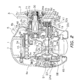
FIG. 2 is a cross-sectional view of the dual-bearing reel; -
FIG. 3 is a side view of the second side cover seen from its rear side; -
FIG. 4 is a cross-sectional view of a second side cover of the dual-bearing reel; -
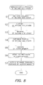
FIG. 5 is a flowchart representing a manufacturing process of the second side cover; and -
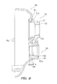
FIG. 6 is a diagram, corresponding toFIG. 4 , according to another exemplary embodiment. - As illustrated in
FIG. 1 , a fishing reel according to an exemplary embodiment of the present invention is a low-profile dual-bearing reel for bait casting. The dual-bearing reel includes a reel unit 1, ahandle 2, and astar drag 3. Thehandle 2, which is used for rotating a spool, is disposed on a lateral side of the reel unit 1. Thestar drag 3, which is used for regulating drag, is disposed on a reel unit 1 side of thehandle 2. - As illustrated in
FIG. 2 , the reel unit 1 includes aframe 5, a pair of afirst side cover 6a and asecond side cover 6b (an exemplary main body member), a first bearingmounting part 70, and a second bearingmounting part 80. The first and second side covers 6a and 6b are made of aluminum alloy and are attached to the both lateral sides of theframe 5. Each of the first and second side covers 6a and 6b includes a chromium plating layer as a corrosion-resistant film on the surface thereof. As illustrated inFIG. 2 , thesecond side cover 6b includes afirst opening 6c and asecond opening 6d on the lateral part thereof. The first andsecond openings bearing mounting part 70 is swaged to thefirst opening 6c, while the secondbearing mounting part 80 is swaged to thesecond opening 6d. As illustrated inFIG. 1 , the reel unit 1 further includes a front cover 7 and a thumb rest 8. The front cover 7 covers the front side of the reel unit 1, while the thumb rest 8 covers the top side of the reel unit 1. Aspool 12 for winding the fishing line is rotatably and detachably mounted in the inside of the reel unit 1. - The
frame 5 includes a pair of afirst side plate 5a and asecond side plate 5b and a plurality of coupling portions (not illustrated in the figures). The first andsecond plates second side plates - As illustrated in
FIG. 2 , theframe 5 accommodates therein thespool 12, alevel winding mechanism 15, and aclutch lever 17. Thespool 12 is disposed while the rotary axis thereof is arranged in a direction perpendicular to a fishing rod. Thelevel winding mechanism 15 is configured to uniformly wind the fishing line onto thespool 12. Theclutch lever 17 functions as a thumb pad in thumbing the fishing line. Thespool 12 can pass through anopening 5d of thefirst side plate 5a. Further, a gear mechanism 18, aclutch mechanism 13, a clutch engaging/disengaging mechanism 19, a drag mechanism 21, and a casting control mechanism 22 are disposed between theframe 5 and thesecond side cover 6b. The gear mechanism 18 is configured to transmit rotational force from thehandle 2 to thespool 12 and thelevel winding mechanism 15. The clutch engaging/disengaging mechanism 19 is configured to control and engage/disengage theclutch mechanism 13 in accordance with an operation of theclutch lever 17. The casting control mechanism 22 is configured to regulate resistive force to be caused during rotation of thespool 12. Further, acentrifugal braking mechanism 23 is disposed between theframe 5 and thefirst side cover 6a for inhibiting occurrence of backlash in casting. - As illustrated in
FIG. 2 , thespool 12 is formed by cutting magnesium alloy and has abobbin trunk 12b, a pair offlanges 12a, and a boss 12c. Thebobbin trunk 12b is a tubular portion for winding the fishing line about the outer periphery thereof. Theflanges 12a protrude radially outwards from the both axial ends of thebobbin trunk 12b. The boss 12c is formed in the inner peripheral part of thebobbin trunk 12b. The inner periphery of the boss 12c is fixed onto a spool shaft 16. Thebobbin trunk 12b, theflanges 12a and the boss 12c are integrally formed by a member made of magnesium alloy. Thespool 12 is non-rotatably fixed onto the spool shaft 16, for instance, by serration coupling. The method of fixing thespool 12 onto the spool shaft 16 is not limited to methods using convex and concave (e.g., serration coupling). A variety of coupling methods (bonding, insert molding, etc.) can be used as the method of fixing thespool 12 onto the spool shaft 16. - As illustrated in
FIG. 2 , the spool shaft 16 is formed in a rod shape by cutting stainless alloy. The spool shaft 16 extends outwards of thesecond side cover 6b while penetrating through thesecond side plate 5b. One end (i.e., the extended end) of the spool shaft 16 is rotatably supported by asecond bearing 24b mounted to the secondbearing mounting part 80 fitted to thesecond opening 6d formed in thesecond side cover 6b. On the other hand, the other end of the spool shaft 16 is rotatably supported within thecentrifugal braking mechanism 23 through afourth bearing 24d. The second andfourth bearings second side plate 5b. Anengaging pin 16b, which forms a part of theclutch mechanism 13, is fixed to the right end of the large-diameter portion 16a. The engagingpin 16b penetrates the large-diameter portion 16a along its diameter while the both ends thereof radially protrude therefrom. - As illustrated in
FIG. 2 , the gear mechanism 18 includes ahandle shaft 30, adrive gear 31 and apinion gear 32. Thedrive gear 31 is fixed onto thehandle shaft 30. Thepinion gear 32 is a tubular gear meshing with thedrive gear 31. To reduce the height of the thumb rest 8, the vertical position of thehandle shaft 30 of the gear mechanism 18 is lower than that in the well-known structure. Therefore, the lower parts of thesecond side plate 5b and thesecond side cover 6b, which accommodates the gear mechanism 18, are positioned lower than the lower parts of thefirst side plate 5a and thefirst side cover 6a. Further as illustrated inFIG. 2 , thehandle shaft 30 is rotatably supported by thesecond side cover 6b through afirst bearing 24a mounted to the firstbearing mounting part 70 fitted to thefirst opening 6c formed in thesecond side cover 6b. As illustrated inFIG. 2 , thefirst bearing 24a is a ball bearing. - As illustrated in
FIGS. 2 to 4 , the firstbearing mounting part 70 is a tubular member fixed to thesecond side cover 6b. As illustrated in enlarged views ofFIGS. 3 and4 , the firstbearing mounting part 70 includes a firstouter member 71 and a firstinner member 72. The firstouter member 71 is a tubular member swaged to thefirst opening 6c of thesecond side cover 6b. The firstinner member 72 is a tubular member screwed and bonded to the inner periphery of the firstouter member 71. As illustrated inFIG. 4 , the firstinner member 72 has a first innerperipheral surface 72a on the inner periphery thereof. The innerperipheral surface 72a receives thefirst bearing 24a (seeFIG. 2 ) mounted thereto. The innerperipheral surface 72a is formed by cutting to be executed after the firstouter member 71 is swaged to thefirst opening 6c. As illustrated inFIG. 4 , the firstinner member 72 has a first male threadedportion 72b on the outer periphery thereof. The first male threadedportion 72b can be screwed into a first female threadedportion 71a formed on the inner periphery of the firstouter member 71. As illustrated inFIG. 4 , the firstouter member 71 has the first female threadedportion 71a and a second innerperipheral surface 71b on the inner periphery thereof. The first female threadedportion 71a is screwed onto the first male threadedportion 72b of the firstinner member 72. The second innerperipheral surface 71b is disposed on the left side of the first female threadedportion 71a (seeFIG. 4 ) and receives a one-way clutch 25 (seeFIG. 2 ) to be mounted thereto. - The first
inner member 72 is mounted to the inner periphery of the firstouter member 71 from the right side inFIG. 4 while the first male threadedportion 72b is screwed into the first female threadedportion 71a. Both of the first female threadedportion 71a and the first male threadedportion 72b are left-handed screws for preventing the firstinner member 72 from being loosened in executing a cutting process from the left side inFIG. 4 . Further, the first female threadedportion 71a and the first male threadedportion 72b are bonded to each other. On the other hand, the firstinner member 72 includes a slot (not illustrated in the figures) on the right end surface thereof. A tool is engaged with the slot for screwing the firstinner member 72 into the firstouter member 71. Further, the firstouter member 71 has a firstflanged portion 71c on the outer periphery thereof. The firstflanged portion 71c functions as a stopper in fixing the firstouter member 71 to thefirst opening 6c. - The first
outer member 71 is made of aluminum alloy and includes an anodized coating as a corrosion-resistant coating on the surface thereof. On the other hand, the firstinner member 72 is made of stainless alloy as a corrosion-resistant material. Therefore, it is not required to from an anodized coating as a corrosion-resistant coating on the surface of the firstinner member 72. - As illustrated in
FIGS. 2 to 4 , the secondbearing mounting part 80 is a tubular member fixed to thesecond side cover 6b. As illustrated in enlarged views ofFIGS. 3 and4 , the secondbearing mounting part 80 includes a secondouter member 81 and a secondinner member 82. The secondouter member 81 is a tubular member swaged to thesecond opening 6d of thesecond side cover 6b. The secondinner member 82 is a tubular member screwed into and fixed by means of bonding to the inner periphery of the secondouter member 81. As illustrated inFIG. 4 , the secondouter member 81 has a second female threadedportion 81a and a second flanged portion 81b. The second female threadedportion 81a can be screwed onto a second male threaded portion 82c formed on the outer periphery of the secondinner member 82. The second flanged portion 81b is formed on the outer periphery of the secondouter member 81 and functions as a stopper in fixing the secondouter member 81 to thesecond opening 6d of thesecond side cover 6b. The secondinner member 82 has a third innerperipheral surface 82a and a fourth innerperipheral surface 82b. Thesecond bearing 24b (seeFIG. 2 ) is mounted to the third innerperipheral surface 82a, whereas a third bearing 24c (seeFIG. 2 ) is mounted to the fourth innerperipheral surface 82b. The third and fourth innerperipheral surfaces peripheral surface 72a of the firstinner member 72. - The second
inner member 82 is mounted to the inner periphery of the secondouter member 81 from the left side inFIG. 4 while the second male threaded portion 82c is screwed into the second female threadedportion 81a. Similarly to the first female threadedportion 71a and the first male threadedportion 72b, the second female threadedportion 81a and the second male threaded portion 82c are left handed screws and prevent the secondinner member 82 from being loosened in executing a cutting process from the left side inFIG. 4 . Further, the second female threadedportion 81a and the second male threaded portion 82c are bonded to each other. As illustrated inFIG. 3 , the secondinner member 82 further has aslot 82d on the left end surface thereof (seeFIG. 4 ). A tool is engaged with theslot 82d for screwing the secondinner member 82 into the secondouter member 81. - The second
outer member 81 is made of aluminum alloy and includes an anodized coating as a corrosion-resistant coating on the surface thereof. The secondinner member 82 is made of stainless alloy as a corrosion-resistant material. Therefore, it is not required to form an anodized coating as a corrosion-resistant coating on the surface of the secondinner member 82. -
FIG. 5 represents a series of steps of attaching the aforementioned first and secondbearing mounting parts second side cover 6b. - First in Step S1, die cast molding of aluminum alloy is executed for forming the
second side cover 6b having the first andsecond openings - Next in Step S2, cutting of the
second side cover 6b is executed simultaneously for removing burr produced in the molding and for forming elements such as the first andsecond openings positioning holes 6e for processing references (seeFIG. 3 ) and tworecesses 6f (seeFIG. 3 ) receiving twopositioning pins 6g (seeFIGS. 3 and4 ) press-inserted therein for positioning thesecond side cover 6b in attaching thesecond side cover 6b to theframe 5. - Next in Step S3, masking of the
positioning holes 6e is executed by inserting screws into thepositioning holes 6e. - Next in Step S4, a chromium plating layer is formed on the surface of the
second side cover 6b by means of chromium plating. - Next in Step S5, the first
outer member 71 and the secondouter member 81, each of which is made of aluminum alloy and includes an anodized coating on the surface thereof, are swaged to thefirst opening 6c and thesecond opening 6d of thesecond side cover 6b, respectively. - Next in Step S6, to form the first and second
bearing mounting parts inner member 72 and the secondinner member 82 are screwed into and fixed by means of bonding to the inner periphery of the firstouter member 71 and that of the secondouter member 81, respectively. - Finally in Step S7, the inner
peripheral surface 72a of the firstinner member 72 of the firstbearing mounting part 70 and the third and fourth innerperipheral surfaces inner member 82 of the secondbearing mounting part 80 are cut with reference to thepositioning holes 6e. - It should be noted that the
positioning holes 6e are filled with silicone grease after processing (e.g., in assembling) and are clogged with screws or etc. that anticorrosion processing is executed. Further, the positioning pins 6g are press-inserted into therecesses 6f. The positioning pins 6g are used for positioning thesecond side cover 6b in attaching thesecond side cover 6b to theframe 5. - As illustrated in
FIG. 2 , thepinion gear 32 is a tubular member that the spool shaft 16 penetrates the center part thereof at a predetermined interval. Thepinion gear 32 extends from the outside to the inside of thesecond side plate 5b. Thepinion gear 32 is mounted onto the spool shaft 16 while being axially movable. Further, the left end (seeFIG. 2 ) of thepinion gear 32 is supported by thesecond side plate 5b through afifth bearing 24e while being rotatable and axially movable. On the other hand, the right end (seeFIG. 2 ) of thepinion gear 32 is supported by the secondbearing mounting portion 80 of thesecond side cover 6b through the third bearing 24c while being rotatable and axially movable. The third andfifth bearings 24c and 24e are both ball bearings. - The
pinion gear 32 includes ateeth portion 32a, a meshing portion 32b and a narrowedportion 32c. Theteeth portion 32a is formed on the outer periphery of the right end (seeFIG. 2 ) of thepinion gear 32 for meshing with thedrive gear 31. The meshing portion 32b is formed on the other end (i.e., the left end inFIG. 2 ) of thepinion gear 32. The narrowedportion 32c is formed between theteeth portion 32a and the meshing portion 32b. The meshing portion 32b is a recessed groove formed on the end surface of thepinion gear 32 along the diameter of thepinion gear 32. The engagingpin 16b, which is fixed to the spool shaft 16 while penetrating therethrough, is engaged with the meshing portion 32b. When thepinion gear 32 is herein moved outwards and theengaging pin 16b of the spool shaft 16 is disengaged from the meshing portion 32b of thepinion gear 32, the rotational force from thehandle shaft 30 is not transmitted to thespool 12. Theclutch mechanism 13 is formed by the meshing portion 32b and theengaging pin 16b. - As illustrated in
FIG. 2 , theclutch lever 17 is disposed behind thespool 12 while being disposed on the rear part of the space interposed between the pair of thefirst side plate 5a and thesecond side plate 5b. - As illustrated in
FIG. 2 , the clutch engaging/disengaging mechanism 19 includes aclutch yoke 40. Theclutch yoke 40 is disposed on the outer peripheral side of the spool shaft 16. Theclutch yoke 40 is supported by two pins 41 (only one of thepins 41 is illustrated) while being movable in parallel to the axis of the spool shaft 16. Further, theclutch yoke 40 has an engaging portion 40a on the middle part thereof. The engaging portion 40a is engaged with the narrowedportion 32c of thepinion gear 32. Further, aspring 42 is disposed on the outer periphery of each of thepins 41 supporting theclutch yoke 40 while being disposed between theclutch yoke 40 and thesecond side cover 6b. Theclutch yoke 40 is constantly urged to the clutch-on side by thesprings 42. - With the structure, the
pinion gear 32 is normally positioned in an inward clutch engaged position. More specifically, the meshing portion 32b of thepinion gear 32 and theengaging pin 16b of the spool shaft 16 are engaged and thus a clutch-on state is produced. On the other hand, when thepinion gear 32 is moved outwards by theclutch yoke 40, the meshing portion 32b and theengaging pin 16b are disengaged from each other and thus a clutch-off state is produced. - The drag mechanism 21 includes a
friction plate 45 and a pressure plate 46. Thefriction plate 45 is configured to be pressed by thedrive gear 31. The pressure plate 46 serves to press thefriction plate 45 towards thedrive gear 31 with predetermined force in conjunction with a rotary operation of thestar drag 3. - The casting control mechanism 22 includes a plurality of
friction plates 51 and abrake cap 52. Thefriction plates 51 abut to the both ends of the spool shaft 16 from the axially outside of the spool shaft 20. Thebrake cap 52 is configured to regulate abutting pressure of thefriction plates 51 against the spool shaft 16. The left-side friction plate 51 is attached to the inside of abrake case 65. - As illustrated in
FIG. 2 , thecentrifugal braking mechanism 23 includes abrake member 68, a rotary member 66 and six moving members 67. Thebrake member 68 is fixed to thebrake case 65. The rotary member 66 is fixed to the spool shaft 16 while being concentrically disposed on the inner peripheral side of thebrake member 68. The moving members 67 are mounted to the rotary member 66 while being radially movable. - According to the dual-bearing reel thus structured, it is not required to form a corrosion-resistant coating on each of the first inner
peripheral surface 72a of the firstinner member 72 and the third and fourth innerperipheral surfaces inner member 82 by forming each of the first and secondinner members outer members outer member 71 and that of the secondouter member 81 can be kept high, while the inner periphery of the firstinner member 72 and that of the second inner member 82 (i.e., the first innerperipheral surface 72a, the third innerperipheral surface 82a and the fourth innerperipheral surface 82b) can be highly accurately formed. - (a) The
second side cover 6b of the dual-bearing reel has been exemplified as the fishing component according to the present invention. However, the fishing component is not limited to thesecond side cover 6b. For example, the present invention can be also applied to a reel unit for an electric reel or a counter reel and a reel unit for a spinning reel. - (b) In the aforementioned exemplary embodiment, the
first side cover 6a, thesecond side cover 6b, the firstouter member 71, and the secondouter member 81 are made of aluminum alloy whereas the firstinner member 72 and the secondinner member 82 are made of stainless alloy. However, materials of these members are not limited to the aforementioned metal materials. For example, thesecond side cover 6b, the firstouter member 71 and the secondouter member 81 can be made of light metal such as magnesium alloy. - (c) In the aforementioned exemplary embodiment, a chromium plating layer as a corrosion-resistant coating is formed on the surface of the
second side cover 6b, whereas an anodized coating as a corrosion-resistant coating is formed on the surface of the firstouter member 71 and that of the secondouter member 81. However, the corrosion-resistant coatings can not be limited to the above. Alternatively, a layer plated with any other metal and a painted layer can be used as the corrosion-resistant coatings. - (d) In the aforementioned exemplary embodiment, the second
inner member 82 has two inner peripheral surfaces, i.e., the third innerperipheral surface 82a that thesecond bearing 24b is mounted and the fourth innerperipheral surface 82b that the third bearing 24c is mounted. However, the secondinner member 82 can have a single inner peripheral surface that a single bearing is mounted. Alternatively, the secondinner member 82 can include two inner members, i.e., an inner member having the third innerperipheral surface 82a that thesecond bearing 24b is mounted and an inner member having the fourth innerperipheral surface 82b that the third bearing 24c is mounted. - (e) In the aforementioned exemplary embodiment, after the first
outer member 71 and the secondouter member 81 are fixed to thesecond side cover 6b, the firstinner member 72 is mounted and fixed to the firstouter member 71 while the secondinner member 82 is mounted and fixed to the secondouter member 81. However, the firstouter member 71 and the secondouter member 81 can be fixed to thesecond side cover 6b after the firstinner member 72 is mounted and fixed to the firstouter member 71 while the secondinner member 82 is mounted and fixed to the secondouter member 81. - (f) In the aforementioned exemplary embodiment, the first
outer member 71 is swaged to thefirst opening 6c of thesecond side cover 6b, while the secondouter member 81 is swaged to thesecond opening 6d of thesecond side cover 6b. However, the fixation method of these members is not limited to the above. For example, any other suitable fixation methods such as bonding, welding or insert molding can be herein used. - (g) In the aforementioned exemplary embodiment, each of the first and second
inner members - (h) In the aforementioned exemplary embodiment, the
second side cover 6b includes the first andsecond openings outer members second openings second side cover 6b, the firstouter member 71 and the secondouter member 81 can be integrally formed as illustrated inFIG. 6 . - According to the fishing-reel reel unit of the present invention, the first outer member has the corrosion-resistant coating formed thereon, while the first inner member is made of a corrosion-resistant material and is fixed as a separate member to the inner peripheral side of the first outer member. Thus, it is not required to form a corrosion-resistant coating on the inner peripheral surface of the first inner member by forming the first inner member with a corrosion-resistant material and forming the corrosion-resistant coating only on the first outer member. As a result, corrosion-resistance of the first outer member and that of the first inner member can be kept high, while the inner periphery of the first inner member can be highly accurately formed.
Claims (7)
- A fishing-reel reel unit, comprising:a main body member (6c);a first outer member (71) being mounted on the main body member (6c), the first outer member (71) including a corrosion-resistant coating formed thereon; andcharacterized in that the fishing-reel reel unit comprisesa first inner member (72) being formed in a tubular shape, the first inner member (72) being fixed to an inner periphery of the first outer member (71), the first inner member (72) having a first inner peripheral surface (72a) on which a first bearing (24a) is mounted, the first inner member made of a corrosion-resistant material.
- The fishing-reel reel unit according to claim 1, wherein
the main body member (6b) further includes a first opening (6c), and
the first outer member (71) is fixed to the first opening (6c). - The fishing-reel reel unit according to claim 2, wherein
at least an outer surface of the main body member (6c) is covered with a corrosion-resistant coating formed after the first opening is formed. - The fishing-reel reel unit according to claim 1, wherein
the first outer member (71) is integrally formed with the main body member (6b). - The fishing-reel reel unit according to one of claims 2 and 3, wherein
the first outer member (71) is made of light metal and includes a corrosion-resistant coating formed on an outer surface thereof, and
the first inner member (72) is made of stainless alloy. - The fishing-reel reel unit according to one of claims 1 to 5, wherein
the main body member (6b) further includes a second outer member,
the second outer member (81) is disposed away from the first outer member,
the fishing-reel reel unit further includes a second inner member,
the second inner member (82) is fixed to an inner peripheral side of the second outer member, and
the second inner member includes a second inner peripheral surface to which a second bearing is mounted. - A fishing reel, comprising:the fishing-reel reel unit according to one of claims 1 to 6.
Applications Claiming Priority (1)
| Application Number | Priority Date | Filing Date | Title |
|---|---|---|---|
| JP2011244152A JP5956741B2 (en) | 2011-11-08 | 2011-11-08 | Fishing reel body and fishing reel |
Publications (2)
| Publication Number | Publication Date |
|---|---|
| EP2591670A1 EP2591670A1 (en) | 2013-05-15 |
| EP2591670B1 true EP2591670B1 (en) | 2014-07-30 |
Family
ID=47172456
Family Applications (1)
| Application Number | Title | Priority Date | Filing Date |
|---|---|---|---|
| EP12191198.6A Active EP2591670B1 (en) | 2011-11-08 | 2012-11-05 | Fishing-reel reel unit and fishing reel |
Country Status (7)
| Country | Link |
|---|---|
| US (1) | US8985493B2 (en) |
| EP (1) | EP2591670B1 (en) |
| JP (1) | JP5956741B2 (en) |
| KR (1) | KR101979018B1 (en) |
| CN (1) | CN103081875B (en) |
| MY (1) | MY164165A (en) |
| TW (1) | TWI612888B (en) |
Families Citing this family (12)
| Publication number | Priority date | Publication date | Assignee | Title |
|---|---|---|---|---|
| JP6517466B2 (en) * | 2012-12-28 | 2019-05-22 | 株式会社シマノ | Double bearing reel |
| JP6218532B2 (en) * | 2013-09-27 | 2017-10-25 | グローブライド株式会社 | Fishing reel |
| JP6376740B2 (en) * | 2013-10-01 | 2018-08-22 | 株式会社シマノ | Double bearing reel |
| JP6395383B2 (en) * | 2014-01-23 | 2018-09-26 | 株式会社シマノ | Fishing reel |
| JP6615462B2 (en) * | 2015-02-12 | 2019-12-04 | 株式会社シマノ | Double bearing reel |
| JP2018113917A (en) * | 2017-01-19 | 2018-07-26 | 株式会社シマノ | Double bearing reel |
| JP7082868B2 (en) * | 2017-11-07 | 2022-06-09 | 株式会社シマノ | Double bearing reel |
| JP7064323B2 (en) * | 2017-12-06 | 2022-05-10 | 株式会社シマノ | Bearing holding structure of fishing reel and fishing reel |
| JP7082901B2 (en) * | 2018-04-26 | 2022-06-09 | シマノコンポネンツ マレーシア エスディーエヌ.ビーエッチディー. | Double bearing reel |
| TWI813778B (en) | 2019-01-10 | 2023-09-01 | 日商島野股份有限公司 | Dual bearing cord reel |
| JP7311443B2 (en) * | 2020-03-03 | 2023-07-19 | グローブライド株式会社 | Structural member of fishing reel and manufacturing method thereof |
| JP2023084191A (en) * | 2021-12-07 | 2023-06-19 | グローブライド株式会社 | Fishing reel, and corrosion member mounted on the same |
Family Cites Families (26)
| Publication number | Priority date | Publication date | Assignee | Title |
|---|---|---|---|---|
| JPS59152221U (en) * | 1983-03-31 | 1984-10-12 | 三菱重工業株式会社 | bearing structure |
| JPH0629027Y2 (en) * | 1986-04-09 | 1994-08-10 | ダイワ精工株式会社 | Fishing reel |
| JP2514526Y2 (en) * | 1990-07-26 | 1996-10-23 | 株式会社シマノ | Spinning reel |
| JP2966490B2 (en) * | 1990-08-10 | 1999-10-25 | 株式会社シマノ | Manufacturing method of dual bearing reel body |
| JP3066990B2 (en) * | 1991-11-26 | 2000-07-17 | 株式会社シマノ | Spinning reel and manufacturing method thereof |
| US6095444A (en) * | 1996-01-24 | 2000-08-01 | Daiwa Seiko, Inc. | Attachment unit for a double bearing type reel for fishing |
| SG80003A1 (en) | 1997-12-10 | 2001-04-17 | Shimano Kk | Mechanical assembly with incompatible metallic materials |
| JP3445934B2 (en) * | 1998-05-26 | 2003-09-16 | 株式会社シマノ | Surface structure of fishing gear |
| JP3558896B2 (en) * | 1998-10-23 | 2004-08-25 | ダイワ精工株式会社 | Fishing reel |
| JP2000312549A (en) * | 1999-04-30 | 2000-11-14 | Daiwa Seiko Inc | Component member of reel for fishing |
| JP3819198B2 (en) * | 1999-11-19 | 2006-09-06 | 株式会社シマノ | Reel body of double-bearing reel |
| JP2001321036A (en) * | 2000-03-08 | 2001-11-20 | Daiwa Seiko Inc | Constructive member for fishing reel |
| JP3772265B2 (en) * | 2000-05-17 | 2006-05-10 | 株式会社シマノ | Painted parts for fishing |
| JP3961757B2 (en) * | 2000-09-29 | 2007-08-22 | 株式会社シマノ | Parts support structure for fishing reel |
| JP4553495B2 (en) * | 2001-01-24 | 2010-09-29 | 株式会社シマノ | Fastening structure for fishing parts |
| JP2004082612A (en) * | 2002-08-28 | 2004-03-18 | Shimano Inc | Outdoor appearance component |
| JP2005210998A (en) * | 2004-01-30 | 2005-08-11 | Daiwa Seiko Inc | Fishing reel |
| JP4535742B2 (en) * | 2004-02-03 | 2010-09-01 | 株式会社シマノ | Fishing reel, fishing information display device and fishing information display system |
| JP2005270012A (en) * | 2004-03-25 | 2005-10-06 | Daiwa Seiko Inc | Reel for fishing |
| US20060289690A1 (en) * | 2005-06-01 | 2006-12-28 | Marsh Jeffrey D | Bait casting reel and method |
| JP2007159427A (en) * | 2005-12-09 | 2007-06-28 | Shimano Inc | Part for fishing |
| JP4901500B2 (en) * | 2007-01-23 | 2012-03-21 | 株式会社シマノ | Handle shaft support structure for dual-bearing reels |
| JP4963291B2 (en) * | 2007-12-27 | 2012-06-27 | 株式会社シマノ | Fishing reel spool |
| JP5143648B2 (en) * | 2008-07-08 | 2013-02-13 | 株式会社シマノ | Lever drag type double bearing reel |
| JP2010043733A (en) * | 2008-07-15 | 2010-02-25 | Jtekt Corp | Rolling bearing with pulley |
| JP2010190403A (en) * | 2009-02-20 | 2010-09-02 | Sii Micro Precision Kk | Rolling bearing device and pivot device |
-
2011
- 2011-11-08 JP JP2011244152A patent/JP5956741B2/en active Active
-
2012
- 2012-09-24 US US13/625,449 patent/US8985493B2/en active Active
- 2012-10-01 TW TW101136213A patent/TWI612888B/en active
- 2012-10-16 MY MYPI2012700773A patent/MY164165A/en unknown
- 2012-10-18 CN CN201210397578.6A patent/CN103081875B/en active Active
- 2012-10-23 KR KR1020120117667A patent/KR101979018B1/en active IP Right Grant
- 2012-11-05 EP EP12191198.6A patent/EP2591670B1/en active Active
Also Published As
| Publication number | Publication date |
|---|---|
| JP2013099265A (en) | 2013-05-23 |
| CN103081875A (en) | 2013-05-08 |
| CN103081875B (en) | 2016-08-03 |
| US8985493B2 (en) | 2015-03-24 |
| US20130153700A1 (en) | 2013-06-20 |
| JP5956741B2 (en) | 2016-07-27 |
| TW201328594A (en) | 2013-07-16 |
| EP2591670A1 (en) | 2013-05-15 |
| MY164165A (en) | 2017-11-30 |
| KR20130050880A (en) | 2013-05-16 |
| TWI612888B (en) | 2018-02-01 |
| KR101979018B1 (en) | 2019-05-16 |
Similar Documents
| Publication | Publication Date | Title |
|---|---|---|
| EP2591670B1 (en) | Fishing-reel reel unit and fishing reel | |
| JP2013099265A5 (en) | ||
| EP2517559B1 (en) | Centrifugal brake device for dual-bearing reel | |
| EP2494866B1 (en) | Spool of fishing reel | |
| JP5291904B2 (en) | Double bearing reel cast control mechanism | |
| EP2784353B1 (en) | Reel part for fishing reel | |
| US8882014B2 (en) | Fishing-reel reel unit and fishing reel | |
| EP2591669B1 (en) | Fishing-reel reel unit and fishing reel | |
| EP2749165B1 (en) | Dual-bearing reel | |
| JP2014197986A5 (en) | ||
| EP1514472A1 (en) | Reel unit for a dual bearing reel | |
| JP2013099264A5 (en) | ||
| JP2013000043A5 (en) |
Legal Events
| Date | Code | Title | Description |
|---|---|---|---|
| PUAI | Public reference made under article 153(3) epc to a published international application that has entered the european phase |
Free format text: ORIGINAL CODE: 0009012 |
|
| AK | Designated contracting states |
Kind code of ref document: A1 Designated state(s): AL AT BE BG CH CY CZ DE DK EE ES FI FR GB GR HR HU IE IS IT LI LT LU LV MC MK MT NL NO PL PT RO RS SE SI SK SM TR |
|
| AX | Request for extension of the european patent |
Extension state: BA ME |
|
| 17P | Request for examination filed |
Effective date: 20130808 |
|
| RBV | Designated contracting states (corrected) |
Designated state(s): AL AT BE BG CH CY CZ DE DK EE ES FI FR GB GR HR HU IE IS IT LI LT LU LV MC MK MT NL NO PL PT RO RS SE SI SK SM TR |
|
| GRAP | Despatch of communication of intention to grant a patent |
Free format text: ORIGINAL CODE: EPIDOSNIGR1 |
|
| INTG | Intention to grant announced |
Effective date: 20140226 |
|
| RIN1 | Information on inventor provided before grant (corrected) |
Inventor name: NIITSUMA, AKIRA Inventor name: HIRAYAMA, HIROKAZU Inventor name: NAKAGAWA, SHOUJI Inventor name: TAKECHI, KUNIO |
|
| GRAS | Grant fee paid |
Free format text: ORIGINAL CODE: EPIDOSNIGR3 |
|
| GRAA | (expected) grant |
Free format text: ORIGINAL CODE: 0009210 |
|
| AK | Designated contracting states |
Kind code of ref document: B1 Designated state(s): AL AT BE BG CH CY CZ DE DK EE ES FI FR GB GR HR HU IE IS IT LI LT LU LV MC MK MT NL NO PL PT RO RS SE SI SK SM TR |
|
| REG | Reference to a national code |
Ref country code: GB Ref legal event code: FG4D |
|
| REG | Reference to a national code |
Ref country code: CH Ref legal event code: EP |
|
| REG | Reference to a national code |
Ref country code: AT Ref legal event code: REF Ref document number: 679491 Country of ref document: AT Kind code of ref document: T Effective date: 20140815 |
|
| REG | Reference to a national code |
Ref country code: IE Ref legal event code: FG4D |
|
| REG | Reference to a national code |
Ref country code: DE Ref legal event code: R096 Ref document number: 602012002578 Country of ref document: DE Effective date: 20140918 |
|
| REG | Reference to a national code |
Ref country code: AT Ref legal event code: MK05 Ref document number: 679491 Country of ref document: AT Kind code of ref document: T Effective date: 20140730 |
|
| REG | Reference to a national code |
Ref country code: NL Ref legal event code: VDEP Effective date: 20140730 |
|
| REG | Reference to a national code |
Ref country code: LT Ref legal event code: MG4D |
|
| PG25 | Lapsed in a contracting state [announced via postgrant information from national office to epo] |
Ref country code: FI Free format text: LAPSE BECAUSE OF FAILURE TO SUBMIT A TRANSLATION OF THE DESCRIPTION OR TO PAY THE FEE WITHIN THE PRESCRIBED TIME-LIMIT Effective date: 20140730 Ref country code: LT Free format text: LAPSE BECAUSE OF FAILURE TO SUBMIT A TRANSLATION OF THE DESCRIPTION OR TO PAY THE FEE WITHIN THE PRESCRIBED TIME-LIMIT Effective date: 20140730 Ref country code: SE Free format text: LAPSE BECAUSE OF FAILURE TO SUBMIT A TRANSLATION OF THE DESCRIPTION OR TO PAY THE FEE WITHIN THE PRESCRIBED TIME-LIMIT Effective date: 20140730 Ref country code: PT Free format text: LAPSE BECAUSE OF FAILURE TO SUBMIT A TRANSLATION OF THE DESCRIPTION OR TO PAY THE FEE WITHIN THE PRESCRIBED TIME-LIMIT Effective date: 20141202 Ref country code: GR Free format text: LAPSE BECAUSE OF FAILURE TO SUBMIT A TRANSLATION OF THE DESCRIPTION OR TO PAY THE FEE WITHIN THE PRESCRIBED TIME-LIMIT Effective date: 20141031 Ref country code: BG Free format text: LAPSE BECAUSE OF FAILURE TO SUBMIT A TRANSLATION OF THE DESCRIPTION OR TO PAY THE FEE WITHIN THE PRESCRIBED TIME-LIMIT Effective date: 20141030 Ref country code: ES Free format text: LAPSE BECAUSE OF FAILURE TO SUBMIT A TRANSLATION OF THE DESCRIPTION OR TO PAY THE FEE WITHIN THE PRESCRIBED TIME-LIMIT Effective date: 20140730 Ref country code: NO Free format text: LAPSE BECAUSE OF FAILURE TO SUBMIT A TRANSLATION OF THE DESCRIPTION OR TO PAY THE FEE WITHIN THE PRESCRIBED TIME-LIMIT Effective date: 20141030 |
|
| PG25 | Lapsed in a contracting state [announced via postgrant information from national office to epo] |
Ref country code: LV Free format text: LAPSE BECAUSE OF FAILURE TO SUBMIT A TRANSLATION OF THE DESCRIPTION OR TO PAY THE FEE WITHIN THE PRESCRIBED TIME-LIMIT Effective date: 20140730 Ref country code: HR Free format text: LAPSE BECAUSE OF FAILURE TO SUBMIT A TRANSLATION OF THE DESCRIPTION OR TO PAY THE FEE WITHIN THE PRESCRIBED TIME-LIMIT Effective date: 20140730 Ref country code: AT Free format text: LAPSE BECAUSE OF FAILURE TO SUBMIT A TRANSLATION OF THE DESCRIPTION OR TO PAY THE FEE WITHIN THE PRESCRIBED TIME-LIMIT Effective date: 20140730 Ref country code: IS Free format text: LAPSE BECAUSE OF FAILURE TO SUBMIT A TRANSLATION OF THE DESCRIPTION OR TO PAY THE FEE WITHIN THE PRESCRIBED TIME-LIMIT Effective date: 20141130 Ref country code: RS Free format text: LAPSE BECAUSE OF FAILURE TO SUBMIT A TRANSLATION OF THE DESCRIPTION OR TO PAY THE FEE WITHIN THE PRESCRIBED TIME-LIMIT Effective date: 20140730 Ref country code: PL Free format text: LAPSE BECAUSE OF FAILURE TO SUBMIT A TRANSLATION OF THE DESCRIPTION OR TO PAY THE FEE WITHIN THE PRESCRIBED TIME-LIMIT Effective date: 20140730 Ref country code: NL Free format text: LAPSE BECAUSE OF FAILURE TO SUBMIT A TRANSLATION OF THE DESCRIPTION OR TO PAY THE FEE WITHIN THE PRESCRIBED TIME-LIMIT Effective date: 20140730 Ref country code: CY Free format text: LAPSE BECAUSE OF FAILURE TO SUBMIT A TRANSLATION OF THE DESCRIPTION OR TO PAY THE FEE WITHIN THE PRESCRIBED TIME-LIMIT Effective date: 20140730 |
|
| PG25 | Lapsed in a contracting state [announced via postgrant information from national office to epo] |
Ref country code: CZ Free format text: LAPSE BECAUSE OF FAILURE TO SUBMIT A TRANSLATION OF THE DESCRIPTION OR TO PAY THE FEE WITHIN THE PRESCRIBED TIME-LIMIT Effective date: 20140730 Ref country code: SK Free format text: LAPSE BECAUSE OF FAILURE TO SUBMIT A TRANSLATION OF THE DESCRIPTION OR TO PAY THE FEE WITHIN THE PRESCRIBED TIME-LIMIT Effective date: 20140730 Ref country code: IT Free format text: LAPSE BECAUSE OF FAILURE TO SUBMIT A TRANSLATION OF THE DESCRIPTION OR TO PAY THE FEE WITHIN THE PRESCRIBED TIME-LIMIT Effective date: 20140730 Ref country code: EE Free format text: LAPSE BECAUSE OF FAILURE TO SUBMIT A TRANSLATION OF THE DESCRIPTION OR TO PAY THE FEE WITHIN THE PRESCRIBED TIME-LIMIT Effective date: 20140730 Ref country code: RO Free format text: LAPSE BECAUSE OF FAILURE TO SUBMIT A TRANSLATION OF THE DESCRIPTION OR TO PAY THE FEE WITHIN THE PRESCRIBED TIME-LIMIT Effective date: 20140730 Ref country code: DK Free format text: LAPSE BECAUSE OF FAILURE TO SUBMIT A TRANSLATION OF THE DESCRIPTION OR TO PAY THE FEE WITHIN THE PRESCRIBED TIME-LIMIT Effective date: 20140730 |
|
| REG | Reference to a national code |
Ref country code: DE Ref legal event code: R097 Ref document number: 602012002578 Country of ref document: DE |
|
| PLBE | No opposition filed within time limit |
Free format text: ORIGINAL CODE: 0009261 |
|
| STAA | Information on the status of an ep patent application or granted ep patent |
Free format text: STATUS: NO OPPOSITION FILED WITHIN TIME LIMIT |
|
| PG25 | Lapsed in a contracting state [announced via postgrant information from national office to epo] |
Ref country code: BE Free format text: LAPSE BECAUSE OF NON-PAYMENT OF DUE FEES Effective date: 20141130 Ref country code: MC Free format text: LAPSE BECAUSE OF FAILURE TO SUBMIT A TRANSLATION OF THE DESCRIPTION OR TO PAY THE FEE WITHIN THE PRESCRIBED TIME-LIMIT Effective date: 20140730 |
|
| 26N | No opposition filed |
Effective date: 20150504 |
|
| REG | Reference to a national code |
Ref country code: IE Ref legal event code: MM4A |
|
| REG | Reference to a national code |
Ref country code: FR Ref legal event code: PLFP Year of fee payment: 4 |
|
| PG25 | Lapsed in a contracting state [announced via postgrant information from national office to epo] |
Ref country code: IE Free format text: LAPSE BECAUSE OF NON-PAYMENT OF DUE FEES Effective date: 20141105 |
|
| PG25 | Lapsed in a contracting state [announced via postgrant information from national office to epo] |
Ref country code: SI Free format text: LAPSE BECAUSE OF FAILURE TO SUBMIT A TRANSLATION OF THE DESCRIPTION OR TO PAY THE FEE WITHIN THE PRESCRIBED TIME-LIMIT Effective date: 20140730 |
|
| REG | Reference to a national code |
Ref country code: CH Ref legal event code: PL |
|
| PG25 | Lapsed in a contracting state [announced via postgrant information from national office to epo] |
Ref country code: TR Free format text: LAPSE BECAUSE OF FAILURE TO SUBMIT A TRANSLATION OF THE DESCRIPTION OR TO PAY THE FEE WITHIN THE PRESCRIBED TIME-LIMIT Effective date: 20140730 Ref country code: HU Free format text: LAPSE BECAUSE OF FAILURE TO SUBMIT A TRANSLATION OF THE DESCRIPTION OR TO PAY THE FEE WITHIN THE PRESCRIBED TIME-LIMIT; INVALID AB INITIO Effective date: 20121105 Ref country code: BE Free format text: LAPSE BECAUSE OF FAILURE TO SUBMIT A TRANSLATION OF THE DESCRIPTION OR TO PAY THE FEE WITHIN THE PRESCRIBED TIME-LIMIT Effective date: 20140730 Ref country code: LI Free format text: LAPSE BECAUSE OF NON-PAYMENT OF DUE FEES Effective date: 20151130 Ref country code: MT Free format text: LAPSE BECAUSE OF FAILURE TO SUBMIT A TRANSLATION OF THE DESCRIPTION OR TO PAY THE FEE WITHIN THE PRESCRIBED TIME-LIMIT Effective date: 20140730 Ref country code: CH Free format text: LAPSE BECAUSE OF NON-PAYMENT OF DUE FEES Effective date: 20151130 |
|
| REG | Reference to a national code |
Ref country code: FR Ref legal event code: PLFP Year of fee payment: 5 |
|
| PGFP | Annual fee paid to national office [announced via postgrant information from national office to epo] |
Ref country code: LU Payment date: 20161027 Year of fee payment: 5 |
|
| PGFP | Annual fee paid to national office [announced via postgrant information from national office to epo] |
Ref country code: FR Payment date: 20161014 Year of fee payment: 5 |
|
| PG25 | Lapsed in a contracting state [announced via postgrant information from national office to epo] |
Ref country code: SM Free format text: LAPSE BECAUSE OF FAILURE TO SUBMIT A TRANSLATION OF THE DESCRIPTION OR TO PAY THE FEE WITHIN THE PRESCRIBED TIME-LIMIT Effective date: 20140730 |
|
| PG25 | Lapsed in a contracting state [announced via postgrant information from national office to epo] |
Ref country code: MK Free format text: LAPSE BECAUSE OF FAILURE TO SUBMIT A TRANSLATION OF THE DESCRIPTION OR TO PAY THE FEE WITHIN THE PRESCRIBED TIME-LIMIT Effective date: 20140730 |
|
| PG25 | Lapsed in a contracting state [announced via postgrant information from national office to epo] |
Ref country code: LU Free format text: LAPSE BECAUSE OF NON-PAYMENT OF DUE FEES Effective date: 20171105 |
|
| REG | Reference to a national code |
Ref country code: FR Ref legal event code: ST Effective date: 20180731 |
|
| PG25 | Lapsed in a contracting state [announced via postgrant information from national office to epo] |
Ref country code: FR Free format text: LAPSE BECAUSE OF NON-PAYMENT OF DUE FEES Effective date: 20171130 Ref country code: AL Free format text: LAPSE BECAUSE OF FAILURE TO SUBMIT A TRANSLATION OF THE DESCRIPTION OR TO PAY THE FEE WITHIN THE PRESCRIBED TIME-LIMIT Effective date: 20140730 |
|
| REG | Reference to a national code |
Ref country code: DE Ref legal event code: R082 Ref document number: 602012002578 Country of ref document: DE Representative=s name: SONNENBERG HARRISON PARTNERSCHAFT MBB, DE Ref country code: DE Ref legal event code: R082 Ref document number: 602012002578 Country of ref document: DE Representative=s name: SONNENBERG HARRISON PARTNERSCHAFT MBB PATENT- , DE |
|
| PGFP | Annual fee paid to national office [announced via postgrant information from national office to epo] |
Ref country code: GB Payment date: 20201028 Year of fee payment: 9 |
|
| GBPC | Gb: european patent ceased through non-payment of renewal fee |
Effective date: 20211105 |
|
| PG25 | Lapsed in a contracting state [announced via postgrant information from national office to epo] |
Ref country code: GB Free format text: LAPSE BECAUSE OF NON-PAYMENT OF DUE FEES Effective date: 20211105 |
|
| P01 | Opt-out of the competence of the unified patent court (upc) registered |
Effective date: 20230424 |
|
| PGFP | Annual fee paid to national office [announced via postgrant information from national office to epo] |
Ref country code: DE Payment date: 20230929 Year of fee payment: 12 |