EP2591303B9 - A plate heat exchanger - Google Patents
A plate heat exchanger Download PDFInfo
- Publication number
- EP2591303B9 EP2591303B9 EP11727424.1A EP11727424A EP2591303B9 EP 2591303 B9 EP2591303 B9 EP 2591303B9 EP 11727424 A EP11727424 A EP 11727424A EP 2591303 B9 EP2591303 B9 EP 2591303B9
- Authority
- EP
- European Patent Office
- Prior art keywords
- plates
- ridges
- grooves
- heat exchanger
- plate
- Prior art date
- Legal status (The legal status is an assumption and is not a legal conclusion. Google has not performed a legal analysis and makes no representation as to the accuracy of the status listed.)
- Active
Links
Images

Classifications
-
- F—MECHANICAL ENGINEERING; LIGHTING; HEATING; WEAPONS; BLASTING
- F28—HEAT EXCHANGE IN GENERAL
- F28F—DETAILS OF HEAT-EXCHANGE AND HEAT-TRANSFER APPARATUS, OF GENERAL APPLICATION
- F28F3/00—Plate-like or laminated elements; Assemblies of plate-like or laminated elements
- F28F3/02—Elements or assemblies thereof with means for increasing heat-transfer area, e.g. with fins, with recesses, with corrugations
- F28F3/04—Elements or assemblies thereof with means for increasing heat-transfer area, e.g. with fins, with recesses, with corrugations the means being integral with the element
-
- F—MECHANICAL ENGINEERING; LIGHTING; HEATING; WEAPONS; BLASTING
- F28—HEAT EXCHANGE IN GENERAL
- F28F—DETAILS OF HEAT-EXCHANGE AND HEAT-TRANSFER APPARATUS, OF GENERAL APPLICATION
- F28F3/00—Plate-like or laminated elements; Assemblies of plate-like or laminated elements
- F28F3/08—Elements constructed for building-up into stacks, e.g. capable of being taken apart for cleaning
-
- F—MECHANICAL ENGINEERING; LIGHTING; HEATING; WEAPONS; BLASTING
- F28—HEAT EXCHANGE IN GENERAL
- F28D—HEAT-EXCHANGE APPARATUS, NOT PROVIDED FOR IN ANOTHER SUBCLASS, IN WHICH THE HEAT-EXCHANGE MEDIA DO NOT COME INTO DIRECT CONTACT
- F28D1/00—Heat-exchange apparatus having stationary conduit assemblies for one heat-exchange medium only, the media being in contact with different sides of the conduit wall, in which the other heat-exchange medium is a large body of fluid, e.g. domestic or motor car radiators
-
- F—MECHANICAL ENGINEERING; LIGHTING; HEATING; WEAPONS; BLASTING
- F28—HEAT EXCHANGE IN GENERAL
- F28D—HEAT-EXCHANGE APPARATUS, NOT PROVIDED FOR IN ANOTHER SUBCLASS, IN WHICH THE HEAT-EXCHANGE MEDIA DO NOT COME INTO DIRECT CONTACT
- F28D1/00—Heat-exchange apparatus having stationary conduit assemblies for one heat-exchange medium only, the media being in contact with different sides of the conduit wall, in which the other heat-exchange medium is a large body of fluid, e.g. domestic or motor car radiators
- F28D1/02—Heat-exchange apparatus having stationary conduit assemblies for one heat-exchange medium only, the media being in contact with different sides of the conduit wall, in which the other heat-exchange medium is a large body of fluid, e.g. domestic or motor car radiators with heat-exchange conduits immersed in the body of fluid
- F28D1/03—Heat-exchange apparatus having stationary conduit assemblies for one heat-exchange medium only, the media being in contact with different sides of the conduit wall, in which the other heat-exchange medium is a large body of fluid, e.g. domestic or motor car radiators with heat-exchange conduits immersed in the body of fluid with plate-like or laminated conduits
-
- F—MECHANICAL ENGINEERING; LIGHTING; HEATING; WEAPONS; BLASTING
- F28—HEAT EXCHANGE IN GENERAL
- F28D—HEAT-EXCHANGE APPARATUS, NOT PROVIDED FOR IN ANOTHER SUBCLASS, IN WHICH THE HEAT-EXCHANGE MEDIA DO NOT COME INTO DIRECT CONTACT
- F28D9/00—Heat-exchange apparatus having stationary plate-like or laminated conduit assemblies for both heat-exchange media, the media being in contact with different sides of a conduit wall
- F28D9/0031—Heat-exchange apparatus having stationary plate-like or laminated conduit assemblies for both heat-exchange media, the media being in contact with different sides of a conduit wall the conduits for one heat-exchange medium being formed by paired plates touching each other
-
- F—MECHANICAL ENGINEERING; LIGHTING; HEATING; WEAPONS; BLASTING
- F28—HEAT EXCHANGE IN GENERAL
- F28F—DETAILS OF HEAT-EXCHANGE AND HEAT-TRANSFER APPARATUS, OF GENERAL APPLICATION
- F28F3/00—Plate-like or laminated elements; Assemblies of plate-like or laminated elements
-
- F—MECHANICAL ENGINEERING; LIGHTING; HEATING; WEAPONS; BLASTING
- F28—HEAT EXCHANGE IN GENERAL
- F28F—DETAILS OF HEAT-EXCHANGE AND HEAT-TRANSFER APPARATUS, OF GENERAL APPLICATION
- F28F3/00—Plate-like or laminated elements; Assemblies of plate-like or laminated elements
- F28F3/02—Elements or assemblies thereof with means for increasing heat-transfer area, e.g. with fins, with recesses, with corrugations
-
- F—MECHANICAL ENGINEERING; LIGHTING; HEATING; WEAPONS; BLASTING
- F28—HEAT EXCHANGE IN GENERAL
- F28F—DETAILS OF HEAT-EXCHANGE AND HEAT-TRANSFER APPARATUS, OF GENERAL APPLICATION
- F28F3/00—Plate-like or laminated elements; Assemblies of plate-like or laminated elements
- F28F3/02—Elements or assemblies thereof with means for increasing heat-transfer area, e.g. with fins, with recesses, with corrugations
- F28F3/04—Elements or assemblies thereof with means for increasing heat-transfer area, e.g. with fins, with recesses, with corrugations the means being integral with the element
- F28F3/042—Elements or assemblies thereof with means for increasing heat-transfer area, e.g. with fins, with recesses, with corrugations the means being integral with the element in the form of local deformations of the element
- F28F3/046—Elements or assemblies thereof with means for increasing heat-transfer area, e.g. with fins, with recesses, with corrugations the means being integral with the element in the form of local deformations of the element the deformations being linear, e.g. corrugations
-
- F—MECHANICAL ENGINEERING; LIGHTING; HEATING; WEAPONS; BLASTING
- F28—HEAT EXCHANGE IN GENERAL
- F28F—DETAILS OF HEAT-EXCHANGE AND HEAT-TRANSFER APPARATUS, OF GENERAL APPLICATION
- F28F3/00—Plate-like or laminated elements; Assemblies of plate-like or laminated elements
- F28F3/02—Elements or assemblies thereof with means for increasing heat-transfer area, e.g. with fins, with recesses, with corrugations
- F28F3/04—Elements or assemblies thereof with means for increasing heat-transfer area, e.g. with fins, with recesses, with corrugations the means being integral with the element
- F28F3/048—Elements or assemblies thereof with means for increasing heat-transfer area, e.g. with fins, with recesses, with corrugations the means being integral with the element in the form of ribs integral with the element or local variations in thickness of the element, e.g. grooves, microchannels
Definitions
- the present invention relates to a plate heat exchanger for exchanging heat between media, the heat exchanger comprising a number of stacked plates, the plates being provided with a first, large scale pressed pattern comprising ridges and grooves intended to keep first and second pairs of stacked plates on a distance from one another, such that flow channels for a first medium is formed in spaces between said plate pairs, and to provide contact points between the plate pairs in points where the large scale pressed pattern of neighboring plate pairs contact one another.
- Heat exchangers are widely used for a variety of applications where two media are to exchange heat with one another.
- a brazed plate heat exchanger comprises a number of heat exchanger plates provided with a pressed pattern of ridges and grooves adapted to provide contact points between the plates, hence keeping neighboring plates on a distance from one another under formation of interplate flow channels. Neighboring plates are brazed to one another at the contact points.
- Most brazed plate heat exchangers are "symmetric", i.e. they have the same flow resistance for equal mass flow for all interplate flow channels.
- plate heat exchangers are not known to withstand high pressure; most heat exchangers have a design burst pressure of twenty or thirty bars. This is sufficient for most applications, even for use in refrigeration circuits, but for applications having carbon dioxide as refrigerant, brazed plate heat exchangers have hitherto not been strong enough.
- the present invention solves the above and other problems by a plate heat exchanger for exchanging heat between media, the heat exchanger comprising a number of stacked plates.
- the plates are provided with a first, large scale pressed pattern comprising ridges and grooves intended to keep first and second pairs of stacked plates on a distance from one another, such that flow channels for a first medium is formed in spaces between said plate pairs.
- contact points are provided between the plate pairs in points where the large scale pressed pattern of neighboring plate pairs contact one another.
- the plates of each plate pair are kept on a distance from one another by a small-scale pressed pattern comprising ridges and grooves.
- the large-scale ridges R and grooves G may be arranged as elongate ridges and grooves running obliquely over the width of the heat exchanger plates, wherein the ridges and grooves of adjacent plate pairs cross one another when the plate pairs are stacked onto one another.
- the large-scale ridges and grooves may be arranged in a herringbone pattern, wherein apexes of the herringbone pattern of adjacent plates of adjacent plate pairs point in reverse directions.
- the heat exchanger plates may be brazed to one another.
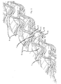
- FIG. 1 four heat exchanger plates A, B, C and D are shown in a sectioned perspective view. All four plates are provided with a large scale pressed pattern of ridges R and depressions D, running obliquely across the width of a heat exchanger plate (not shown).
- the heat exchanger plates are arranged such that a heat exchanger pair comprising the heat exchanger plates A and B is arranged such that the ridges R and grooves G of the large scale pressed pattern run parallel and synchronously with each other.
- the plates C and D form another pair of heat exchanger plates wherein the ridges R and grooves G run parallel and synchronously with each other.
- the two pairs of plates A, B and C, D, respectively are placed such that the ridges R and grooves G of the plates B and C cross to form contact points between the plates B and C.
- the contact points between the ridges R and grooves G will keep the plates on a distance from one another, hence forming a flow channel BC.
- All heat exchanger plates A, B C and D are also provided with a small-scale pressed pattern comprising ridges r and grooves g.
- the ridges and grooves r, g are integrated in the large scale pattern comprising the ridges R and grooves G, and arranged such that the grooves g of the heat exchanger plate D cross ridges r of the heat exchanger plate C, in order to form contact points between the plates C and D, such that the heat exchanger plates are kept on a distance from one another under formation of narrow flow channels CD, while the contact points provide a connection, which, after a brazing operation to be explained later, keep the plates bonded to one another.
- the heat exchanger plates A and B are also provided with small-scale grooves g and small-scale ridges r, such that the plates A and B are kept on a distance from another under formation of flow channels AB.
- the heat exchanger plates of the heat exchanger are also provided with edge portions designed to co-act with edge portions of adjacent plates to form a sealed circumferential edge portion, also in a way well known by persons skilled in the art..
- the port openings communicating with the flow channels defined by the small-scale grooves and ridges are smaller than the port openings defined by the large-scale grooves and ridges.
- the flow channels AB and CD, formed by the small scale pressed pattern with the ridges r and the grooves g will meander in a way defined by the large scale pressed pattern. This means that the effective length of these flow channels will be larger as compared to the efficient length of the flow channels formed by the large scale pressed pattern comprising the ridges and grooves R and G, respectively.
- One further benefit of the heat exchanger according to the present invention is that it is possible to have varying burst pressure capabilities of the large channels BC and the small channels AB and CD. This can be achieved by arranging the ridges r and the grooves r close to one another; if the ridges r and grooves g are located close to one another, more contact points between the plates will be formed; hence, the burst pressure will increase.
- the ridges R, r and the grooves G, g have been described as elongate ridges and grooves crossing one another.
- the ridges and grooves R, r, G, g, respectively may be in the form of "dimples", i.e. smoothed conical depressions and projections.
- the plates A, B, C and D of a heat exchanger according to the present invention are preferably brazed to one another, but it is also possible to design the edge portions (not shown) and the port areas to host gaskets to form a gasket sealed heat exchanger.
Landscapes
- Engineering & Computer Science (AREA)
- Physics & Mathematics (AREA)
- Thermal Sciences (AREA)
- Mechanical Engineering (AREA)
- General Engineering & Computer Science (AREA)
- Heat-Exchange Devices With Radiators And Conduit Assemblies (AREA)
- Defrosting Systems (AREA)
- Thermotherapy And Cooling Therapy Devices (AREA)
Description
- The present invention relates to a plate heat exchanger for exchanging heat between media, the heat exchanger comprising a number of stacked plates, the plates being provided with a first, large scale pressed pattern comprising ridges and grooves intended to keep first and second pairs of stacked plates on a distance from one another, such that flow channels for a first medium is formed in spaces between said plate pairs, and to provide contact points between the plate pairs in points where the large scale pressed pattern of neighboring plate pairs contact one another.
- Heat exchangers are widely used for a variety of applications where two media are to exchange heat with one another.
- Plate heat exchangers, especially brazed plate heat exchangers, have over the years proven to be the most efficient and economical solutions for most applications. As well known by persons skilled in the art, a brazed plate heat exchanger comprises a number of heat exchanger plates provided with a pressed pattern of ridges and grooves adapted to provide contact points between the plates, hence keeping neighboring plates on a distance from one another under formation of interplate flow channels. Neighboring plates are brazed to one another at the contact points. Most brazed plate heat exchangers are "symmetric", i.e. they have the same flow resistance for equal mass flow for all interplate flow channels.
- Moreover, plate heat exchangers are not known to withstand high pressure; most heat exchangers have a design burst pressure of twenty or thirty bars. This is sufficient for most applications, even for use in refrigeration circuits, but for applications having carbon dioxide as refrigerant, brazed plate heat exchangers have hitherto not been strong enough.
- Some efforts have been made in order to increase the design pressure of the brazed plate heat exchangers, for example providing an external edge of the heat exchanger with a reinforcing structure.
- Another solution is suggested by document
US-6,016,865 which proposes a brazed plate heat exchanger that is specially aimed for a heat exchange between a fluid at a relatively high pressure and a fluid at a relatively low pressure. - For decades, it has been known that the design pressure of a brazed heat exchanger increases if the pressed pattern of the heat exchanger plates is "narrow", i.e. exhibits a small distance between rides and grooves of the pressed pattern of the heat exchanger plates.
- As well known by persons skilled in the art, in most applications it is not necessary that all flow channels have the same design pressure. In most cases, the refrigerant flow channels require a much higher design pressure. Having flow channels for the media to exchange heat with the refrigerant with a high design pressure is often inevitable, however pointless. On the contrary, it is often detrimental to have flow channels with a high design pressure for this media; with a high design pressure, the pressure drop increases due to the high surface density of contact points between the plates, and the small distance between the plates.
- One other problem with the known heat exchangers is that they have the same length of the channels. This is not very efficient seen from a heat transfer point of view since. As an example, the heat transfer rate between e.g. a brine solution to metal is considerably higher than between coolant and metal. It would hence be desired to increase the length of the coolant flow passages while keeping the length of the brine channels constant.
- The present invention solves the above and other problems by a plate heat exchanger for exchanging heat between media, the heat exchanger comprising a number of stacked plates. The plates are provided with a first, large scale pressed pattern comprising ridges and grooves intended to keep first and second pairs of stacked plates on a distance from one another, such that flow channels for a first medium is formed in spaces between said plate pairs. Moreover, contact points are provided between the plate pairs in points where the large scale pressed pattern of neighboring plate pairs contact one another. The plates of each plate pair are kept on a distance from one another by a small-scale pressed pattern comprising ridges and grooves.
- The large-scale ridges R and grooves G may be arranged as elongate ridges and grooves running obliquely over the width of the heat exchanger plates, wherein the ridges and grooves of adjacent plate pairs cross one another when the plate pairs are stacked onto one another.
- In another embodiment, the large-scale ridges and grooves may be arranged in a herringbone pattern, wherein apexes of the herringbone pattern of adjacent plates of adjacent plate pairs point in reverse directions.
- In order to come to a compact and strong heat exchanger, the heat exchanger plates may be brazed to one another.
- In the following, the invention will be described with reference to the appended drawings, wherein:
-
Fig. 1 is a sectioned perspective view of four heat exchanger plates comprised in the heat exchanger according to the invention and -
Fig. 2 is a section view showing a randomly chosen section of the four plates ofFig. 1 . - In
Fig. 1 , four heat exchanger plates A, B, C and D are shown in a sectioned perspective view. All four plates are provided with a large scale pressed pattern of ridges R and depressions D, running obliquely across the width of a heat exchanger plate (not shown). - The heat exchanger plates are arranged such that a heat exchanger pair comprising the heat exchanger plates A and B is arranged such that the ridges R and grooves G of the large scale pressed pattern run parallel and synchronously with each other. The plates C and D form another pair of heat exchanger plates wherein the ridges R and grooves G run parallel and synchronously with each other. In the stack of heat exchanger plates forming the heat exchanger, the two pairs of plates A, B and C, D, respectively, are placed such that the ridges R and grooves G of the plates B and C cross to form contact points between the plates B and C. The contact points between the ridges R and grooves G will keep the plates on a distance from one another, hence forming a flow channel BC.
- All heat exchanger plates A, B C and D are also provided with a small-scale pressed pattern comprising ridges r and grooves g. The ridges and grooves r, g are integrated in the large scale pattern comprising the ridges R and grooves G, and arranged such that the grooves g of the heat exchanger plate D cross ridges r of the heat exchanger plate C, in order to form contact points between the plates C and D, such that the heat exchanger plates are kept on a distance from one another under formation of narrow flow channels CD, while the contact points provide a connection, which, after a brazing operation to be explained later, keep the plates bonded to one another. The heat exchanger plates A and B are also provided with small-scale grooves g and small-scale ridges r, such that the plates A and B are kept on a distance from another under formation of flow channels AB.
- In order to allow selective fluid flow through the flow channels AB,CD and CD, provided by the large scale and small scale pressed patterns, areas (not shown) around port openings (not shown) are provided at different heights in a way well known by persons skilled in the art.
- The heat exchanger plates of the heat exchanger are also provided with edge portions designed to co-act with edge portions of adjacent plates to form a sealed circumferential edge portion, also in a way well known by persons skilled in the art..
- In the shown embodiment, four different kinds of heat exchanger plates are used. If the port openings have the same size, it is possible to use two types of heat exchanger plates, but by using four plates, it is possible to have port openings having two different sizes.
- Using two different port sizes is beneficial, since the he flow areas of the flow channels BC formed by the large-scale pressed pattern comprising the grooves G and the ridges R is substantially larger then the flow area of the flow channels AB and CD formed by the small scale pressed pattern comprising the grooves g and the ridges r; having different flow areas of the flow channels and the same size of the port openings will either render the port opening too small or the port opening too large. In a preferred embodiment of the invention, the port openings communicating with the flow channels defined by the small-scale grooves and ridges are smaller than the port openings defined by the large-scale grooves and ridges.
- As could be understood from the above description, the flow channels AB and CD, formed by the small scale pressed pattern with the ridges r and the grooves g will meander in a way defined by the large scale pressed pattern. This means that the effective length of these flow channels will be larger as compared to the efficient length of the flow channels formed by the large scale pressed pattern comprising the ridges and grooves R and G, respectively.
- This is very beneficial when it comes to one of the intended uses of the heat exchanger according to the invention, namely heat exchange between carbon dioxide and a brine solution. As well known by persons skilled in the art, the heat transfer rate between metal and carbon dioxide is significantly lower than between brine solution and metal. By increasing the efficient length of the heat flow channels for the carbon dioxide, the heat exchange capability of the heat exchanger will increase significantly, without increasing the actual length of the heat exchanger.
- As well known by persons skilled in the art of heat exchangers, this is very beneficial in some cases. The heat transfer rate is often lower for the media travelling through the small scale flow channel.
- One further benefit of the heat exchanger according to the present invention is that it is possible to have varying burst pressure capabilities of the large channels BC and the small channels AB and CD. This can be achieved by arranging the ridges r and the grooves r close to one another; if the ridges r and grooves g are located close to one another, more contact points between the plates will be formed; hence, the burst pressure will increase.
- Above, the ridges R, r and the grooves G, g have been described as elongate ridges and grooves crossing one another. In other embodiments of the invention, however, the ridges and grooves R, r, G, g, respectively, may be in the form of "dimples", i.e. smoothed conical depressions and projections. However, it is crucial that there are no "negative" press angles in the pressed pattern; after the pressing of the press pattern, the pressing tool must release the pressed plate.
- The plates A, B, C and D of a heat exchanger according to the present invention are preferably brazed to one another, but it is also possible to design the edge portions (not shown) and the port areas to host gaskets to form a gasket sealed heat exchanger.
Claims (4)
- A plate heat exchanger for exchanging heat between media, the heat exchanger comprising a number of stacked plates (A, B, C, D) arranged in plate pairs (A, B; C,D), the plates (A, B, C, D) being provided with a first, large scale pressed pattern comprising ridges (R) and grooves (G), wherein ridges (R) and grooves (G) of both plates (A, B, C, D) forming a plate pair (A, B; C, D) run parallel and synchronously with each other, wherein said ridges (R) and said grooves (G) provide contact points between the plate pairs (A, B; C, D) in points where the large scale pressed patterns of neighboring plate pairs (A, B; C, D) contact one another such that the plate pairs (A, B; C, D) are kept on a distance from one another such that flow channels (BC) for a first medium are formed in spaces between said plate pairs (A, B; C, D), wherein the plates (A, B, C, D) are also provided with a small-scale pressed pattern comprising ridges (r) and grooves (g) integrated in the large scale pattern, wherein the ridges (r) and the grooves (g) are arranged such that the grooves (g) of one of the plates (D, B) of each of the plate pairs (A, B; C, D) cross the ridges (r) of the other one of the plates (A, C) of each of the plate pairs (A, B; C, D) in order to form contact points between the plates (A, B, C, D) of each of the plate pairs (A, B; C, D) such that the plates (A, B, C, D) of each of the plate pairs (A, B; C, D) are kept on a distance from one another under formation of a narrow flow channel.
- The plate heat exchanger of claim 1, wherein the large-scale ridges R and grooves G are arranged as elongate ridges and grooves running obliquely over the width of the heat exchanger plates, wherein the ridges R and grooves G of adjacent plate pairs cross one another when the plate pairs are stacked onto one another.
- The plate heat exchanger of claim 1, wherein the large-scale ridges R and grooves G are arranged in a herringbone pattern, wherein apexes of the herringbone pattern of adjacent plates of adjacent plate pairs point in reverse directions.
- The heat exchanger of any of the preceding claims, wherein the heat exchanger plates are brazed to one another.
Priority Applications (1)
| Application Number | Priority Date | Filing Date | Title |
|---|---|---|---|
| PL11727424T PL2591303T3 (en) | 2010-07-08 | 2011-06-15 | A plate heat exchanger |
Applications Claiming Priority (2)
| Application Number | Priority Date | Filing Date | Title |
|---|---|---|---|
| SE1050755 | 2010-07-08 | ||
| PCT/EP2011/059965 WO2012004100A1 (en) | 2010-07-08 | 2011-06-15 | A plate heat exchanger |
Publications (3)
| Publication Number | Publication Date |
|---|---|
| EP2591303A1 EP2591303A1 (en) | 2013-05-15 |
| EP2591303B1 EP2591303B1 (en) | 2015-07-22 |
| EP2591303B9 true EP2591303B9 (en) | 2016-02-10 |
Family
ID=44514646
Family Applications (1)
| Application Number | Title | Priority Date | Filing Date |
|---|---|---|---|
| EP11727424.1A Active EP2591303B9 (en) | 2010-07-08 | 2011-06-15 | A plate heat exchanger |
Country Status (10)
| Country | Link |
|---|---|
| US (1) | US9389028B2 (en) |
| EP (1) | EP2591303B9 (en) |
| JP (1) | JP6018053B2 (en) |
| KR (1) | KR101803281B1 (en) |
| CN (1) | CN103026166B (en) |
| DK (1) | DK2591303T5 (en) |
| ES (1) | ES2550483T3 (en) |
| PL (1) | PL2591303T3 (en) |
| PT (1) | PT2591303E (en) |
| WO (1) | WO2012004100A1 (en) |
Families Citing this family (20)
| Publication number | Priority date | Publication date | Assignee | Title |
|---|---|---|---|---|
| US8622115B2 (en) * | 2009-08-19 | 2014-01-07 | Alstom Technology Ltd | Heat transfer element for a rotary regenerative heat exchanger |
| SI3062949T2 (en) * | 2013-10-29 | 2023-08-31 | Swep International Ab | A method of brazing a plate heat exchanger using scren printed brazing material |
| TR201911112T4 (en) * | 2013-12-10 | 2019-08-21 | Swep Int Ab | Heat exchanger with improved flow. |
| US10030916B2 (en) * | 2014-07-29 | 2018-07-24 | Intel Corporation | Fluid flow channel for enhanced heat transfer efficiency |
| EP3225947A1 (en) * | 2016-03-30 | 2017-10-04 | Alfa Laval Corporate AB | Heat transfer plate and plate heat exchanger comprising a plurality of such heat transfer plates |
| CN106440858A (en) * | 2016-10-28 | 2017-02-22 | 佛山顺德宸祥轩电子有限公司 | Energy-storage and energy-saving water heater adopting plate-tube heat exchanger |
| CN106482555A (en) * | 2016-10-28 | 2017-03-08 | 佛山顺德宸祥轩电子有限公司 | A kind of band-tube type heat exchanger |
| CN106440860A (en) * | 2016-10-28 | 2017-02-22 | 佛山顺德宸祥轩电子有限公司 | Tube-plate heat exchanger type asynchronous instant waste heat recycling device |
| CN106369821A (en) * | 2016-10-28 | 2017-02-01 | 佛山顺德宸祥轩电子有限公司 | Tube-on-sheet heat exchanger type multi-split heap pump shower room |
| CN106322764A (en) * | 2016-10-28 | 2017-01-11 | 东莞市康源节能科技有限公司 | A plate and tube heat exchanger type shower room |
| CN106288887A (en) * | 2016-10-28 | 2017-01-04 | 东莞市康源节能科技有限公司 | A plate and tube heat exchanger |
| US10578367B2 (en) | 2016-11-28 | 2020-03-03 | Carrier Corporation | Plate heat exchanger with alternating symmetrical and asymmetrical plates |
| WO2018146560A1 (en) * | 2017-02-13 | 2018-08-16 | Koch Knight, Llc | Heat transfer media |
| EP3447427B1 (en) * | 2017-08-22 | 2020-03-18 | InnoHeat Sweden AB | Heat exchanger |
| EP3447429B1 (en) * | 2017-08-22 | 2023-06-07 | InnoHeat Sweden AB | Heat exchanger plate and heat exchanger |
| USD889420S1 (en) * | 2018-01-05 | 2020-07-07 | Baltimore Aircoil Company, Inc. | Heat exchanger cassette |
| US10677538B2 (en) * | 2018-01-05 | 2020-06-09 | Baltimore Aircoil Company | Indirect heat exchanger |
| US20200166293A1 (en) * | 2018-11-27 | 2020-05-28 | Hamilton Sundstrand Corporation | Weaved cross-flow heat exchanger and method of forming a heat exchanger |
| CN111928705B (en) * | 2019-05-13 | 2022-03-25 | 亚浩电子五金塑胶(惠州)有限公司 | Heat radiator with gravity type loop heat pipe |
| SE545724C2 (en) * | 2020-07-17 | 2023-12-19 | Swep Int Ab | A double wall plate heat exchanger |
Family Cites Families (25)
| Publication number | Priority date | Publication date | Assignee | Title |
|---|---|---|---|---|
| US3469626A (en) * | 1967-01-19 | 1969-09-30 | Apv Co Ltd | Plate heat exchangers |
| US3661203A (en) * | 1969-11-21 | 1972-05-09 | Parkson Corp | Plates for directing the flow of fluids |
| SE8501955D0 (en) * | 1985-04-23 | 1985-04-23 | Alfa Laval Thermal Ab | PLATE HEAT EXCHANGER |
| SE8504379D0 (en) * | 1985-09-23 | 1985-09-23 | Alfa Laval Thermal Ab | PLATTVEMEVEXLARE |
| SE466027B (en) * | 1990-05-16 | 1991-12-02 | Alfa Laval Thermal Ab | DOUBLE WALL PLATE HEAT EXCHANGER WITH LEAKAGE CHANNELS TWO SEALING PARTS |
| SE468685B (en) * | 1991-06-24 | 1993-03-01 | Alfa Laval Thermal Ab | PLATE HEAT EXCHANGE WITH PLATTER THAT HAS AASAR AND RAENNOR THERE AASAR ON A PLATE BASED ON PARALLEL WITH THE SAME CURRENT AASAR ON THE OTHER PLATE |
| CN2119632U (en) * | 1991-12-07 | 1992-10-21 | 天津大学 | Asymmetric plate-type heat exchanger |
| SE9200213D0 (en) * | 1992-01-27 | 1992-01-27 | Alfa Laval Thermal Ab | WELDED PLATE HEAT EXCHANGER |
| DE59309277D1 (en) * | 1993-03-25 | 1999-02-18 | Sulzer Chemtech Ag | Packing element designed as a heat exchanger for mass transfer or mass conversion processes |
| AU7738494A (en) * | 1993-09-27 | 1995-04-18 | Eberhard Paul | Channel heat exchanger |
| FR2714456B1 (en) * | 1993-12-29 | 1996-01-12 | Commissariat Energie Atomique | Improved plate heat exchanger. |
| JP3026231U (en) * | 1995-12-22 | 1996-07-02 | 東洋ラジエーター株式会社 | Oil cooler |
| SE9601438D0 (en) * | 1996-04-16 | 1996-04-16 | Tetra Laval Holdings & Finance | plate heat exchangers |
| JP3147065B2 (en) * | 1997-12-10 | 2001-03-19 | ダイキン工業株式会社 | Plate heat exchanger |
| JP4462653B2 (en) * | 1998-03-26 | 2010-05-12 | 株式会社日阪製作所 | Plate heat exchanger |
| JP2000292079A (en) * | 1999-04-01 | 2000-10-20 | Daikin Ind Ltd | Plate heat exchanger |
| SE514714C2 (en) * | 1999-08-27 | 2001-04-09 | Alfa Laval Ab | Soldered plate heat exchanger with double wall plates without internal contact opposite the solder connections |
| SE516844C3 (en) * | 2000-07-07 | 2002-04-17 | Alfa Laval Ab | Plate heat / plate heat exchanger with electrically heated layers in double wall plate elements |
| ITVR20020051U1 (en) * | 2002-08-26 | 2004-02-27 | Benetton Bruno Ora Onda Spa | PLATE HEAT EXCHANGER. |
| PT1630510E (en) * | 2004-08-28 | 2007-04-30 | Swep Int Ab | A plate heat exchanger |
| FR2897930B1 (en) * | 2006-02-28 | 2008-05-16 | Commissariat Energie Atomique | PLATE HEAT EXCHANGER INCLUDING A DEVICE FOR EVALUATING ITS ENCRYPTION CONDITION |
| JP2008190786A (en) * | 2007-02-05 | 2008-08-21 | Calsonic Kansei Corp | Plate-type heat exchanger |
| DE102008014375A1 (en) * | 2008-03-17 | 2009-09-24 | Behr Gmbh & Co. Kg | Gas cooler e.g. i-flow-cooler, for combustion engine of motor vehicle, has disc elements stacked parallel to each other, and flow paths running parallel to each other in longitudinal direction of cooler over predominant part of its length |
| SE534306C2 (en) * | 2008-06-17 | 2011-07-05 | Alfa Laval Corp Ab | Heat exchanger plate and plate heat exchanger |
| PL2202476T3 (en) * | 2008-12-29 | 2016-09-30 | Method of manufacturing a welded plate heat exchanger |
-
2011
- 2011-06-15 JP JP2013517154A patent/JP6018053B2/en active Active
- 2011-06-15 US US13/808,780 patent/US9389028B2/en active Active
- 2011-06-15 DK DK11727424.1T patent/DK2591303T5/en active
- 2011-06-15 PL PL11727424T patent/PL2591303T3/en unknown
- 2011-06-15 PT PT117274241T patent/PT2591303E/en unknown
- 2011-06-15 KR KR1020137000429A patent/KR101803281B1/en active Active
- 2011-06-15 WO PCT/EP2011/059965 patent/WO2012004100A1/en not_active Ceased
- 2011-06-15 EP EP11727424.1A patent/EP2591303B9/en active Active
- 2011-06-15 CN CN201180033465.1A patent/CN103026166B/en not_active Expired - Fee Related
- 2011-06-15 ES ES11727424.1T patent/ES2550483T3/en active Active
Also Published As
| Publication number | Publication date |
|---|---|
| JP6018053B2 (en) | 2016-11-02 |
| US9389028B2 (en) | 2016-07-12 |
| ES2550483T3 (en) | 2015-11-10 |
| KR101803281B1 (en) | 2017-11-30 |
| CN103026166B (en) | 2016-08-03 |
| EP2591303B1 (en) | 2015-07-22 |
| KR20130114076A (en) | 2013-10-16 |
| DK2591303T3 (en) | 2015-11-02 |
| JP2013530374A (en) | 2013-07-25 |
| EP2591303A1 (en) | 2013-05-15 |
| US20130180699A1 (en) | 2013-07-18 |
| WO2012004100A1 (en) | 2012-01-12 |
| PL2591303T3 (en) | 2015-12-31 |
| ES2550483T9 (en) | 2016-04-14 |
| DK2591303T5 (en) | 2016-04-04 |
| CN103026166A (en) | 2013-04-03 |
| PT2591303E (en) | 2015-11-16 |
Similar Documents
| Publication | Publication Date | Title |
|---|---|---|
| EP2591303B1 (en) | A plate heat exchanger | |
| EP2267391B1 (en) | Asymmetric heat exchanger | |
| EP1630510B2 (en) | A plate heat exchanger | |
| US10473403B2 (en) | Heat exchanger | |
| EP2151653B1 (en) | Micro-channel heat exchanger | |
| JP5106453B2 (en) | Plate heat exchanger and refrigeration air conditioner | |
| US20120125583A1 (en) | Heat exchanger | |
| CN101194137B (en) | Plate heat exchanger with heat exchange structure forming multiple channels in passage | |
| US20110226448A1 (en) | Heat exchanger having winding channels | |
| EP4097413B1 (en) | A brazed plate heat exchanger and use thereof | |
| CN104567509B (en) | A kind of fin-type heat exchange unit and manufacture method and the heat exchanger containing this unit | |
| CN103217049B (en) | A kind of plate type heat exchanger and plate thereof | |
| CN104296586A (en) | Heat exchanger sheet, heat exchanger heat exchange unit and heat exchanger | |
| EP2775246B1 (en) | Dimple pattern gasketed heat exchanger | |
| US20110180247A1 (en) | Heat exchanger | |
| JP4874365B2 (en) | Plate heat exchanger and refrigeration cycle apparatus using the heat exchanger | |
| US11413714B2 (en) | Method for producing a brazed plate heat exchanger | |
| JP2002107073A (en) | Stacked heat exchanger | |
| CN201666748U (en) | Brazed plate heat exchanger | |
| JP2005300062A (en) | Heat exchanger and manufacturing method thereof | |
| CN119153420A (en) | Micro-energy chip and heat exchanger formed by same | |
| JP2000121280A (en) | Plate heat exchanger |
Legal Events
| Date | Code | Title | Description |
|---|---|---|---|
| PUAI | Public reference made under article 153(3) epc to a published international application that has entered the european phase |
Free format text: ORIGINAL CODE: 0009012 |
|
| 17P | Request for examination filed |
Effective date: 20130122 |
|
| AK | Designated contracting states |
Kind code of ref document: A1 Designated state(s): AL AT BE BG CH CY CZ DE DK EE ES FI FR GB GR HR HU IE IS IT LI LT LU LV MC MK MT NL NO PL PT RO RS SE SI SK SM TR |
|
| DAX | Request for extension of the european patent (deleted) | ||
| 17Q | First examination report despatched |
Effective date: 20140429 |
|
| GRAP | Despatch of communication of intention to grant a patent |
Free format text: ORIGINAL CODE: EPIDOSNIGR1 |
|
| INTG | Intention to grant announced |
Effective date: 20150116 |
|
| GRAS | Grant fee paid |
Free format text: ORIGINAL CODE: EPIDOSNIGR3 |
|
| GRAA | (expected) grant |
Free format text: ORIGINAL CODE: 0009210 |
|
| AK | Designated contracting states |
Kind code of ref document: B1 Designated state(s): AL AT BE BG CH CY CZ DE DK EE ES FI FR GB GR HR HU IE IS IT LI LT LU LV MC MK MT NL NO PL PT RO RS SE SI SK SM TR |
|
| REG | Reference to a national code |
Ref country code: GB Ref legal event code: FG4D |
|
| REG | Reference to a national code |
Ref country code: CH Ref legal event code: EP |
|
| REG | Reference to a national code |
Ref country code: IE Ref legal event code: FG4D |
|
| REG | Reference to a national code |
Ref country code: AT Ref legal event code: REF Ref document number: 738155 Country of ref document: AT Kind code of ref document: T Effective date: 20150815 |
|
| REG | Reference to a national code |
Ref country code: DE Ref legal event code: R096 Ref document number: 602011018028 Country of ref document: DE |
|
| REG | Reference to a national code |
Ref country code: CH Ref legal event code: NV Representative=s name: ISLER AND PEDRAZZINI AG, CH |
|
| REG | Reference to a national code |
Ref country code: DK Ref legal event code: T3 Effective date: 20151027 |
|
| REG | Reference to a national code |
Ref country code: SE Ref legal event code: TRGR Ref country code: ES Ref legal event code: FG2A Ref document number: 2550483 Country of ref document: ES Kind code of ref document: T3 Effective date: 20151110 |
|
| REG | Reference to a national code |
Ref country code: PT Ref legal event code: SC4A Free format text: AVAILABILITY OF NATIONAL TRANSLATION Effective date: 20151021 |
|
| REG | Reference to a national code |
Ref country code: AT Ref legal event code: MK05 Ref document number: 738155 Country of ref document: AT Kind code of ref document: T Effective date: 20150722 |
|
| REG | Reference to a national code |
Ref country code: NL Ref legal event code: FP |
|
| REG | Reference to a national code |
Ref country code: LT Ref legal event code: MG4D |
|
| REG | Reference to a national code |
Ref country code: PL Ref legal event code: T3 |
|
| PG25 | Lapsed in a contracting state [announced via postgrant information from national office to epo] |
Ref country code: LV Free format text: LAPSE BECAUSE OF FAILURE TO SUBMIT A TRANSLATION OF THE DESCRIPTION OR TO PAY THE FEE WITHIN THE PRESCRIBED TIME-LIMIT Effective date: 20150722 Ref country code: NO Free format text: LAPSE BECAUSE OF FAILURE TO SUBMIT A TRANSLATION OF THE DESCRIPTION OR TO PAY THE FEE WITHIN THE PRESCRIBED TIME-LIMIT Effective date: 20151022 Ref country code: GR Free format text: LAPSE BECAUSE OF FAILURE TO SUBMIT A TRANSLATION OF THE DESCRIPTION OR TO PAY THE FEE WITHIN THE PRESCRIBED TIME-LIMIT Effective date: 20151023 Ref country code: LT Free format text: LAPSE BECAUSE OF FAILURE TO SUBMIT A TRANSLATION OF THE DESCRIPTION OR TO PAY THE FEE WITHIN THE PRESCRIBED TIME-LIMIT Effective date: 20150722 |
|
| PG25 | Lapsed in a contracting state [announced via postgrant information from national office to epo] |
Ref country code: RS Free format text: LAPSE BECAUSE OF FAILURE TO SUBMIT A TRANSLATION OF THE DESCRIPTION OR TO PAY THE FEE WITHIN THE PRESCRIBED TIME-LIMIT Effective date: 20150722 Ref country code: AT Free format text: LAPSE BECAUSE OF FAILURE TO SUBMIT A TRANSLATION OF THE DESCRIPTION OR TO PAY THE FEE WITHIN THE PRESCRIBED TIME-LIMIT Effective date: 20150722 Ref country code: HR Free format text: LAPSE BECAUSE OF FAILURE TO SUBMIT A TRANSLATION OF THE DESCRIPTION OR TO PAY THE FEE WITHIN THE PRESCRIBED TIME-LIMIT Effective date: 20150722 Ref country code: IS Free format text: LAPSE BECAUSE OF FAILURE TO SUBMIT A TRANSLATION OF THE DESCRIPTION OR TO PAY THE FEE WITHIN THE PRESCRIBED TIME-LIMIT Effective date: 20151122 |
|
| REG | Reference to a national code |
Ref country code: DK Ref legal event code: T5 Effective date: 20160331 |
|
| REG | Reference to a national code |
Ref country code: DE Ref legal event code: R097 Ref document number: 602011018028 Country of ref document: DE |
|
| PG25 | Lapsed in a contracting state [announced via postgrant information from national office to epo] |
Ref country code: CZ Free format text: LAPSE BECAUSE OF FAILURE TO SUBMIT A TRANSLATION OF THE DESCRIPTION OR TO PAY THE FEE WITHIN THE PRESCRIBED TIME-LIMIT Effective date: 20150722 Ref country code: IT Free format text: LAPSE BECAUSE OF FAILURE TO SUBMIT A TRANSLATION OF THE DESCRIPTION OR TO PAY THE FEE WITHIN THE PRESCRIBED TIME-LIMIT Effective date: 20150722 Ref country code: SK Free format text: LAPSE BECAUSE OF FAILURE TO SUBMIT A TRANSLATION OF THE DESCRIPTION OR TO PAY THE FEE WITHIN THE PRESCRIBED TIME-LIMIT Effective date: 20150722 Ref country code: EE Free format text: LAPSE BECAUSE OF FAILURE TO SUBMIT A TRANSLATION OF THE DESCRIPTION OR TO PAY THE FEE WITHIN THE PRESCRIBED TIME-LIMIT Effective date: 20150722 |
|
| PLBE | No opposition filed within time limit |
Free format text: ORIGINAL CODE: 0009261 |
|
| STAA | Information on the status of an ep patent application or granted ep patent |
Free format text: STATUS: NO OPPOSITION FILED WITHIN TIME LIMIT |
|
| PG25 | Lapsed in a contracting state [announced via postgrant information from national office to epo] |
Ref country code: RO Free format text: LAPSE BECAUSE OF FAILURE TO SUBMIT A TRANSLATION OF THE DESCRIPTION OR TO PAY THE FEE WITHIN THE PRESCRIBED TIME-LIMIT Effective date: 20150722 |
|
| REG | Reference to a national code |
Ref country code: FR Ref legal event code: PLFP Year of fee payment: 6 |
|
| 26N | No opposition filed |
Effective date: 20160425 |
|
| PG25 | Lapsed in a contracting state [announced via postgrant information from national office to epo] |
Ref country code: SI Free format text: LAPSE BECAUSE OF FAILURE TO SUBMIT A TRANSLATION OF THE DESCRIPTION OR TO PAY THE FEE WITHIN THE PRESCRIBED TIME-LIMIT Effective date: 20150722 |
|
| PG25 | Lapsed in a contracting state [announced via postgrant information from national office to epo] |
Ref country code: MC Free format text: LAPSE BECAUSE OF FAILURE TO SUBMIT A TRANSLATION OF THE DESCRIPTION OR TO PAY THE FEE WITHIN THE PRESCRIBED TIME-LIMIT Effective date: 20150722 |
|
| REG | Reference to a national code |
Ref country code: IE Ref legal event code: MM4A |
|
| PG25 | Lapsed in a contracting state [announced via postgrant information from national office to epo] |
Ref country code: IE Free format text: LAPSE BECAUSE OF NON-PAYMENT OF DUE FEES Effective date: 20160615 |
|
| REG | Reference to a national code |
Ref country code: FR Ref legal event code: PLFP Year of fee payment: 7 |
|
| PGFP | Annual fee paid to national office [announced via postgrant information from national office to epo] |
Ref country code: CH Payment date: 20170609 Year of fee payment: 7 |
|
| PGFP | Annual fee paid to national office [announced via postgrant information from national office to epo] |
Ref country code: BE Payment date: 20170519 Year of fee payment: 7 Ref country code: PL Payment date: 20170607 Year of fee payment: 7 Ref country code: BE Payment date: 20170615 Year of fee payment: 7 Ref country code: NL Payment date: 20170615 Year of fee payment: 7 Ref country code: PT Payment date: 20170512 Year of fee payment: 7 |
|
| PGFP | Annual fee paid to national office [announced via postgrant information from national office to epo] |
Ref country code: TR Payment date: 20170615 Year of fee payment: 7 |
|
| PGFP | Annual fee paid to national office [announced via postgrant information from national office to epo] |
Ref country code: ES Payment date: 20170727 Year of fee payment: 7 |
|
| PG25 | Lapsed in a contracting state [announced via postgrant information from national office to epo] |
Ref country code: CY Free format text: LAPSE BECAUSE OF FAILURE TO SUBMIT A TRANSLATION OF THE DESCRIPTION OR TO PAY THE FEE WITHIN THE PRESCRIBED TIME-LIMIT Effective date: 20150722 Ref country code: HU Free format text: LAPSE BECAUSE OF FAILURE TO SUBMIT A TRANSLATION OF THE DESCRIPTION OR TO PAY THE FEE WITHIN THE PRESCRIBED TIME-LIMIT; INVALID AB INITIO Effective date: 20110615 Ref country code: SM Free format text: LAPSE BECAUSE OF FAILURE TO SUBMIT A TRANSLATION OF THE DESCRIPTION OR TO PAY THE FEE WITHIN THE PRESCRIBED TIME-LIMIT Effective date: 20150722 |
|
| REG | Reference to a national code |
Ref country code: FR Ref legal event code: PLFP Year of fee payment: 8 |
|
| PG25 | Lapsed in a contracting state [announced via postgrant information from national office to epo] |
Ref country code: MT Free format text: LAPSE BECAUSE OF NON-PAYMENT OF DUE FEES Effective date: 20160630 Ref country code: MK Free format text: LAPSE BECAUSE OF FAILURE TO SUBMIT A TRANSLATION OF THE DESCRIPTION OR TO PAY THE FEE WITHIN THE PRESCRIBED TIME-LIMIT Effective date: 20150722 Ref country code: LU Free format text: LAPSE BECAUSE OF NON-PAYMENT OF DUE FEES Effective date: 20160615 |
|
| PG25 | Lapsed in a contracting state [announced via postgrant information from national office to epo] |
Ref country code: BG Free format text: LAPSE BECAUSE OF FAILURE TO SUBMIT A TRANSLATION OF THE DESCRIPTION OR TO PAY THE FEE WITHIN THE PRESCRIBED TIME-LIMIT Effective date: 20150722 |
|
| PG25 | Lapsed in a contracting state [announced via postgrant information from national office to epo] |
Ref country code: AL Free format text: LAPSE BECAUSE OF FAILURE TO SUBMIT A TRANSLATION OF THE DESCRIPTION OR TO PAY THE FEE WITHIN THE PRESCRIBED TIME-LIMIT Effective date: 20150722 |
|
| REG | Reference to a national code |
Ref country code: DK Ref legal event code: EBP Effective date: 20180630 |
|
| PG25 | Lapsed in a contracting state [announced via postgrant information from national office to epo] |
Ref country code: PT Free format text: LAPSE BECAUSE OF NON-PAYMENT OF DUE FEES Effective date: 20181217 Ref country code: FI Free format text: LAPSE BECAUSE OF NON-PAYMENT OF DUE FEES Effective date: 20180615 |
|
| REG | Reference to a national code |
Ref country code: CH Ref legal event code: PL |
|
| REG | Reference to a national code |
Ref country code: NL Ref legal event code: MM Effective date: 20180701 |
|
| REG | Reference to a national code |
Ref country code: BE Ref legal event code: FP Effective date: 20151016 Ref country code: BE Ref legal event code: MM Effective date: 20180630 |
|
| PG25 | Lapsed in a contracting state [announced via postgrant information from national office to epo] |
Ref country code: NL Free format text: LAPSE BECAUSE OF NON-PAYMENT OF DUE FEES Effective date: 20180701 |
|
| PG25 | Lapsed in a contracting state [announced via postgrant information from national office to epo] |
Ref country code: CH Free format text: LAPSE BECAUSE OF NON-PAYMENT OF DUE FEES Effective date: 20180630 Ref country code: LI Free format text: LAPSE BECAUSE OF NON-PAYMENT OF DUE FEES Effective date: 20180630 |
|
| PG25 | Lapsed in a contracting state [announced via postgrant information from national office to epo] |
Ref country code: BE Free format text: LAPSE BECAUSE OF NON-PAYMENT OF DUE FEES Effective date: 20180630 |
|
| PG25 | Lapsed in a contracting state [announced via postgrant information from national office to epo] |
Ref country code: DK Free format text: LAPSE BECAUSE OF NON-PAYMENT OF DUE FEES Effective date: 20180630 |
|
| REG | Reference to a national code |
Ref country code: ES Ref legal event code: FD2A Effective date: 20190916 |
|
| PG25 | Lapsed in a contracting state [announced via postgrant information from national office to epo] |
Ref country code: ES Free format text: LAPSE BECAUSE OF NON-PAYMENT OF DUE FEES Effective date: 20180616 |
|
| PG25 | Lapsed in a contracting state [announced via postgrant information from national office to epo] |
Ref country code: PL Free format text: LAPSE BECAUSE OF NON-PAYMENT OF DUE FEES Effective date: 20180615 |
|
| PG25 | Lapsed in a contracting state [announced via postgrant information from national office to epo] |
Ref country code: TR Free format text: LAPSE BECAUSE OF NON-PAYMENT OF DUE FEES Effective date: 20180615 |
|
| P01 | Opt-out of the competence of the unified patent court (upc) registered |
Effective date: 20230514 |
|
| PGFP | Annual fee paid to national office [announced via postgrant information from national office to epo] |
Ref country code: GB Payment date: 20230607 Year of fee payment: 13 |
|
| GBPC | Gb: european patent ceased through non-payment of renewal fee |
Effective date: 20240615 |
|
| PG25 | Lapsed in a contracting state [announced via postgrant information from national office to epo] |
Ref country code: GB Free format text: LAPSE BECAUSE OF NON-PAYMENT OF DUE FEES Effective date: 20240615 |
|
| PGFP | Annual fee paid to national office [announced via postgrant information from national office to epo] |
Ref country code: DE Payment date: 20250619 Year of fee payment: 15 |
|
| PGFP | Annual fee paid to national office [announced via postgrant information from national office to epo] |
Ref country code: FR Payment date: 20250610 Year of fee payment: 15 |
|
| PGFP | Annual fee paid to national office [announced via postgrant information from national office to epo] |
Ref country code: SE Payment date: 20250610 Year of fee payment: 15 |