EP2590822B2 - Value document with a transparent ink-accepting layer and with an opaque ink-accepting layer - Google Patents
Value document with a transparent ink-accepting layer and with an opaque ink-accepting layer Download PDFInfo
- Publication number
- EP2590822B2 EP2590822B2 EP11738610.2A EP11738610A EP2590822B2 EP 2590822 B2 EP2590822 B2 EP 2590822B2 EP 11738610 A EP11738610 A EP 11738610A EP 2590822 B2 EP2590822 B2 EP 2590822B2
- Authority
- EP
- European Patent Office
- Prior art keywords
- layer
- ink
- receiving layer
- value
- sub
- Prior art date
- Legal status (The legal status is an assumption and is not a legal conclusion. Google has not performed a legal analysis and makes no representation as to the accuracy of the status listed.)
- Active
Links
- 230000036961 partial effect Effects 0.000 claims description 56
- 239000000758 substrate Substances 0.000 claims description 36
- 239000000945 filler Substances 0.000 claims description 11
- 239000011230 binding agent Substances 0.000 claims description 9
- 239000002985 plastic film Substances 0.000 claims description 9
- 229920006255 plastic film Polymers 0.000 claims description 9
- 239000011888 foil Substances 0.000 claims description 8
- 239000000203 mixture Substances 0.000 claims description 7
- 239000004372 Polyvinyl alcohol Substances 0.000 claims description 5
- VXAUWWUXCIMFIM-UHFFFAOYSA-M aluminum;oxygen(2-);hydroxide Chemical compound [OH-].[O-2].[Al+3] VXAUWWUXCIMFIM-UHFFFAOYSA-M 0.000 claims description 5
- 229910001593 boehmite Inorganic materials 0.000 claims description 5
- 239000006185 dispersion Substances 0.000 claims description 5
- 238000004049 embossing Methods 0.000 claims description 5
- 229920002451 polyvinyl alcohol Polymers 0.000 claims description 5
- VYPSYNLAJGMNEJ-UHFFFAOYSA-N Silicium dioxide Chemical compound O=[Si]=O VYPSYNLAJGMNEJ-UHFFFAOYSA-N 0.000 claims description 4
- 230000003247 decreasing effect Effects 0.000 claims description 4
- FAHBNUUHRFUEAI-UHFFFAOYSA-M hydroxidooxidoaluminium Chemical compound O[Al]=O FAHBNUUHRFUEAI-UHFFFAOYSA-M 0.000 claims description 4
- NIXOWILDQLNWCW-UHFFFAOYSA-M Acrylate Chemical compound [O-]C(=O)C=C NIXOWILDQLNWCW-UHFFFAOYSA-M 0.000 claims description 2
- 229910021536 Zeolite Inorganic materials 0.000 claims description 2
- HNPSIPDUKPIQMN-UHFFFAOYSA-N dioxosilane;oxo(oxoalumanyloxy)alumane Chemical compound O=[Si]=O.O=[Al]O[Al]=O HNPSIPDUKPIQMN-UHFFFAOYSA-N 0.000 claims description 2
- 229920003009 polyurethane dispersion Polymers 0.000 claims description 2
- 239000000741 silica gel Substances 0.000 claims description 2
- 229910002027 silica gel Inorganic materials 0.000 claims description 2
- 239000010457 zeolite Substances 0.000 claims description 2
- 229910018404 Al2 O3 Inorganic materials 0.000 claims 1
- 239000010410 layer Substances 0.000 description 257
- 239000000976 ink Substances 0.000 description 82
- 239000010408 film Substances 0.000 description 24
- 239000012788 optical film Substances 0.000 description 21
- 239000000049 pigment Substances 0.000 description 20
- 238000007639 printing Methods 0.000 description 20
- 230000000694 effects Effects 0.000 description 18
- 229920003023 plastic Polymers 0.000 description 16
- 239000004033 plastic Substances 0.000 description 15
- 239000000463 material Substances 0.000 description 12
- 239000000123 paper Substances 0.000 description 12
- 239000002131 composite material Substances 0.000 description 10
- 229920000642 polymer Polymers 0.000 description 9
- 238000012546 transfer Methods 0.000 description 9
- 238000001035 drying Methods 0.000 description 8
- 239000004922 lacquer Substances 0.000 description 8
- 230000003287 optical effect Effects 0.000 description 8
- 238000000034 method Methods 0.000 description 7
- 239000003973 paint Substances 0.000 description 6
- -1 polyethylene terephthalate Polymers 0.000 description 5
- 230000002829 reductive effect Effects 0.000 description 5
- 239000012790 adhesive layer Substances 0.000 description 4
- 230000007423 decrease Effects 0.000 description 4
- 238000013461 design Methods 0.000 description 4
- 230000000007 visual effect Effects 0.000 description 4
- XLYOFNOQVPJJNP-UHFFFAOYSA-N water Substances O XLYOFNOQVPJJNP-UHFFFAOYSA-N 0.000 description 4
- 239000000654 additive Substances 0.000 description 3
- 230000001070 adhesive effect Effects 0.000 description 3
- 238000011161 development Methods 0.000 description 3
- 230000018109 developmental process Effects 0.000 description 3
- 238000009472 formulation Methods 0.000 description 3
- 230000001771 impaired effect Effects 0.000 description 3
- 239000004973 liquid crystal related substance Substances 0.000 description 3
- 239000002861 polymer material Substances 0.000 description 3
- 229920002635 polyurethane Polymers 0.000 description 3
- 239000004814 polyurethane Substances 0.000 description 3
- 239000011241 protective layer Substances 0.000 description 3
- 229910018072 Al 2 O 3 Inorganic materials 0.000 description 2
- 229920002799 BoPET Polymers 0.000 description 2
- 239000004831 Hot glue Substances 0.000 description 2
- 239000004698 Polyethylene Substances 0.000 description 2
- 239000004743 Polypropylene Substances 0.000 description 2
- PPBRXRYQALVLMV-UHFFFAOYSA-N Styrene Chemical compound C=CC1=CC=CC=C1 PPBRXRYQALVLMV-UHFFFAOYSA-N 0.000 description 2
- 239000000853 adhesive Substances 0.000 description 2
- 238000000576 coating method Methods 0.000 description 2
- 230000006735 deficit Effects 0.000 description 2
- 230000001419 dependent effect Effects 0.000 description 2
- 238000007646 gravure printing Methods 0.000 description 2
- 239000004615 ingredient Substances 0.000 description 2
- 238000004519 manufacturing process Methods 0.000 description 2
- 229920003207 poly(ethylene-2,6-naphthalate) Polymers 0.000 description 2
- 229920001707 polybutylene terephthalate Polymers 0.000 description 2
- 239000011112 polyethylene naphthalate Substances 0.000 description 2
- 229920000139 polyethylene terephthalate Polymers 0.000 description 2
- 239000005020 polyethylene terephthalate Substances 0.000 description 2
- 238000003847 radiation curing Methods 0.000 description 2
- QNRATNLHPGXHMA-XZHTYLCXSA-N (r)-(6-ethoxyquinolin-4-yl)-[(2s,4s,5r)-5-ethyl-1-azabicyclo[2.2.2]octan-2-yl]methanol;hydrochloride Chemical compound Cl.C([C@H]([C@H](C1)CC)C2)CN1[C@@H]2[C@H](O)C1=CC=NC2=CC=C(OCC)C=C21 QNRATNLHPGXHMA-XZHTYLCXSA-N 0.000 description 1
- 229910018626 Al(OH) Inorganic materials 0.000 description 1
- NOWKCMXCCJGMRR-UHFFFAOYSA-N Aziridine Chemical class C1CN1 NOWKCMXCCJGMRR-UHFFFAOYSA-N 0.000 description 1
- 229920000742 Cotton Polymers 0.000 description 1
- 239000004952 Polyamide Substances 0.000 description 1
- 229910010413 TiO 2 Inorganic materials 0.000 description 1
- 238000010521 absorption reaction Methods 0.000 description 1
- NIXOWILDQLNWCW-UHFFFAOYSA-N acrylic acid group Chemical group C(C=C)(=O)O NIXOWILDQLNWCW-UHFFFAOYSA-N 0.000 description 1
- 239000002318 adhesion promoter Substances 0.000 description 1
- 239000002390 adhesive tape Substances 0.000 description 1
- 230000002411 adverse Effects 0.000 description 1
- 125000001931 aliphatic group Chemical group 0.000 description 1
- 230000005540 biological transmission Effects 0.000 description 1
- 150000001718 carbodiimides Chemical class 0.000 description 1
- 239000012876 carrier material Substances 0.000 description 1
- 239000011248 coating agent Substances 0.000 description 1
- 230000001427 coherent effect Effects 0.000 description 1
- 239000003431 cross linking reagent Substances 0.000 description 1
- GYZLOYUZLJXAJU-UHFFFAOYSA-N diglycidyl ether Chemical class C1OC1COCC1CO1 GYZLOYUZLJXAJU-UHFFFAOYSA-N 0.000 description 1
- 230000008030 elimination Effects 0.000 description 1
- 238000003379 elimination reaction Methods 0.000 description 1
- 238000010438 heat treatment Methods 0.000 description 1
- 239000012948 isocyanate Substances 0.000 description 1
- 150000002513 isocyanates Chemical class 0.000 description 1
- 239000002932 luster Substances 0.000 description 1
- 150000007518 monoprotic acids Chemical class 0.000 description 1
- 239000003921 oil Substances 0.000 description 1
- 238000004806 packaging method and process Methods 0.000 description 1
- 239000002245 particle Substances 0.000 description 1
- 229920002647 polyamide Polymers 0.000 description 1
- 229920006267 polyester film Polymers 0.000 description 1
- 229920000573 polyethylene Polymers 0.000 description 1
- 229920001155 polypropylene Polymers 0.000 description 1
- 230000005855 radiation Effects 0.000 description 1
- 238000007650 screen-printing Methods 0.000 description 1
- 239000000377 silicon dioxide Substances 0.000 description 1
- 239000002356 single layer Substances 0.000 description 1
- 239000000126 substance Substances 0.000 description 1
- 239000010409 thin film Substances 0.000 description 1
- 230000007704 transition Effects 0.000 description 1
- 238000012795 verification Methods 0.000 description 1
Images

Classifications
-
- B—PERFORMING OPERATIONS; TRANSPORTING
- B42—BOOKBINDING; ALBUMS; FILES; SPECIAL PRINTED MATTER
- B42D—BOOKS; BOOK COVERS; LOOSE LEAVES; PRINTED MATTER CHARACTERISED BY IDENTIFICATION OR SECURITY FEATURES; PRINTED MATTER OF SPECIAL FORMAT OR STYLE NOT OTHERWISE PROVIDED FOR; DEVICES FOR USE THEREWITH AND NOT OTHERWISE PROVIDED FOR; MOVABLE-STRIP WRITING OR READING APPARATUS
- B42D25/00—Information-bearing cards or sheet-like structures characterised by identification or security features; Manufacture thereof
- B42D25/20—Information-bearing cards or sheet-like structures characterised by identification or security features; Manufacture thereof characterised by a particular use or purpose
- B42D25/29—Securities; Bank notes
-
- B—PERFORMING OPERATIONS; TRANSPORTING
- B42—BOOKBINDING; ALBUMS; FILES; SPECIAL PRINTED MATTER
- B42D—BOOKS; BOOK COVERS; LOOSE LEAVES; PRINTED MATTER CHARACTERISED BY IDENTIFICATION OR SECURITY FEATURES; PRINTED MATTER OF SPECIAL FORMAT OR STYLE NOT OTHERWISE PROVIDED FOR; DEVICES FOR USE THEREWITH AND NOT OTHERWISE PROVIDED FOR; MOVABLE-STRIP WRITING OR READING APPARATUS
- B42D25/00—Information-bearing cards or sheet-like structures characterised by identification or security features; Manufacture thereof
- B42D25/30—Identification or security features, e.g. for preventing forgery
- B42D25/355—Security threads
-
- D—TEXTILES; PAPER
- D21—PAPER-MAKING; PRODUCTION OF CELLULOSE
- D21H—PULP COMPOSITIONS; PREPARATION THEREOF NOT COVERED BY SUBCLASSES D21C OR D21D; IMPREGNATING OR COATING OF PAPER; TREATMENT OF FINISHED PAPER NOT COVERED BY CLASS B31 OR SUBCLASS D21G; PAPER NOT OTHERWISE PROVIDED FOR
- D21H19/00—Coated paper; Coating material
- D21H19/36—Coatings with pigments
- D21H19/38—Coatings with pigments characterised by the pigments
- D21H19/385—Oxides, hydroxides or carbonates
-
- D—TEXTILES; PAPER
- D21—PAPER-MAKING; PRODUCTION OF CELLULOSE
- D21H—PULP COMPOSITIONS; PREPARATION THEREOF NOT COVERED BY SUBCLASSES D21C OR D21D; IMPREGNATING OR COATING OF PAPER; TREATMENT OF FINISHED PAPER NOT COVERED BY CLASS B31 OR SUBCLASS D21G; PAPER NOT OTHERWISE PROVIDED FOR
- D21H19/00—Coated paper; Coating material
- D21H19/36—Coatings with pigments
- D21H19/38—Coatings with pigments characterised by the pigments
- D21H19/40—Coatings with pigments characterised by the pigments siliceous, e.g. clays
-
- D—TEXTILES; PAPER
- D21—PAPER-MAKING; PRODUCTION OF CELLULOSE
- D21H—PULP COMPOSITIONS; PREPARATION THEREOF NOT COVERED BY SUBCLASSES D21C OR D21D; IMPREGNATING OR COATING OF PAPER; TREATMENT OF FINISHED PAPER NOT COVERED BY CLASS B31 OR SUBCLASS D21G; PAPER NOT OTHERWISE PROVIDED FOR
- D21H19/00—Coated paper; Coating material
- D21H19/36—Coatings with pigments
- D21H19/44—Coatings with pigments characterised by the other ingredients, e.g. the binder or dispersing agent
- D21H19/64—Inorganic compounds
-
- D—TEXTILES; PAPER
- D21—PAPER-MAKING; PRODUCTION OF CELLULOSE
- D21H—PULP COMPOSITIONS; PREPARATION THEREOF NOT COVERED BY SUBCLASSES D21C OR D21D; IMPREGNATING OR COATING OF PAPER; TREATMENT OF FINISHED PAPER NOT COVERED BY CLASS B31 OR SUBCLASS D21G; PAPER NOT OTHERWISE PROVIDED FOR
- D21H19/00—Coated paper; Coating material
- D21H19/80—Paper comprising more than one coating
- D21H19/82—Paper comprising more than one coating superposed
-
- D—TEXTILES; PAPER
- D21—PAPER-MAKING; PRODUCTION OF CELLULOSE
- D21H—PULP COMPOSITIONS; PREPARATION THEREOF NOT COVERED BY SUBCLASSES D21C OR D21D; IMPREGNATING OR COATING OF PAPER; TREATMENT OF FINISHED PAPER NOT COVERED BY CLASS B31 OR SUBCLASS D21G; PAPER NOT OTHERWISE PROVIDED FOR
- D21H21/00—Non-fibrous material added to the pulp, characterised by its function, form or properties; Paper-impregnating or coating material, characterised by its function, form or properties
- D21H21/14—Non-fibrous material added to the pulp, characterised by its function, form or properties; Paper-impregnating or coating material, characterised by its function, form or properties characterised by function or properties in or on the paper
- D21H21/40—Agents facilitating proof of genuineness or preventing fraudulent alteration, e.g. for security paper
-
- B—PERFORMING OPERATIONS; TRANSPORTING
- B41—PRINTING; LINING MACHINES; TYPEWRITERS; STAMPS
- B41M—PRINTING, DUPLICATING, MARKING, OR COPYING PROCESSES; COLOUR PRINTING
- B41M5/00—Duplicating or marking methods; Sheet materials for use therein
- B41M5/50—Recording sheets characterised by the coating used to improve ink, dye or pigment receptivity, e.g. for ink-jet or thermal dye transfer recording
- B41M5/52—Macromolecular coatings
- B41M5/5218—Macromolecular coatings characterised by inorganic additives, e.g. pigments, clays
-
- B42D2033/04—
Definitions
- the invention relates to a security element for the production of documents of value and a document of value comprising such a security element.
- Documents of value within the meaning of the present invention are, for example, banknotes, stocks, bonds, certificates, vouchers, checks, lottery tickets, high-quality entry tickets, passports, identity cards, credit cards and other flat objects of value.
- Such flat objects of value can also be, for example, packaging for possibly high-value products.
- the term document of value also includes all preliminary stages of finished documents of value which, for example, are not yet fit for circulation, such as security paper, film or film composites, among others. Such a value document can also only be a part of a valuable object.
- a security element within the meaning of the present invention can be, for example, a window or see-through window formed by a transparent film, a security thread, a feature produced by printing such as a microprint, a film strip, a patch or a label.
- a security element in particular a security element in the form of a security thread or a film strip, can be embodied as an optically variable security element, with an optically variable security element being understood within the meaning of the present invention as an optical element whose visual impression produced by an observer depends on the viewing direction , that is, the viewing angle of the viewer onto the optical element and possibly also from the direction of incidence of an illuminating light beam.
- optically variable security elements are diffraction structures which produce a viewing angle-dependent visual impression, in particular by reconstructing optically perceptible patterns, such as embossed or volume holograms and other kinegrams, such as achromatic matt structures.
- optically variable elements are optical elements that show a so-called color shift effect, such as single- or multi-layer thin-film interference layers or liquid crystal layers, each of which can be present as a continuous layer or in pigment form (so-called effect pigments such as Iriodine).
- lens or micromirror structures within an optically variable security element are usually constructed on the basis of a polymer layer, e.g. a plastic film, or at least comprise a polymer layer as a cover or protective layer.
- security elements In the special case that the optical element is based on a plastic film, the element can be referred to as an optical film element.
- One countermeasure would be to provide the ink acceptance layer with a reduced layer thickness or with such a filler content that the opacity and/or the clouding effect of the ink acceptance layer is reduced in order to ensure improved perceptibility of a security element.
- this has the disadvantage that the adhesion and drying of the printing ink of the further imprint to be applied deteriorates. If good ink acceptance is required, a more or less pronounced haze above the security element must be accepted. If, on the other hand, there is a requirement to produce a clear see-through window, for example, satisfactory ink trapping of the printing ink of the additional print on the window has hitherto not been possible.
- U.S. 5,387,013 discloses a value document according to the preamble of claim 1.
- WO 2008/031170 A1 discloses security devices with radiation curable embossed ink for security documents.
- U.S. 2004/0053017 A1 discloses a watermarked information carrier.
- the object of the present invention is therefore to specify a security element, e.g. an optical film element, for the production of documents of value, which allows good ink acceptance, adhesion and drying of an ink of a further imprint to be applied, without causing the security element to become matt or cloudy. It is also the object of the invention to specify a document of value with such a security element.
- a security element e.g. an optical film element
- ink trapping layers The task of ink trapping layers is to ensure ink trapping, i.e. absorption of the printing ink from another imprint or certain ingredients of such printing inks, such as oils, and thus adhesion and drying of the printing ink in the further imprint.
- the term ink acceptance layer also includes layers understood, which impart improved adhesion to a surface, in particular to a polymer, plastic or film surface.
- the ink-receiving layer can have one or more layers, ie it can be made up of several sub-layers, with the individual layers being homogeneous in each case.
- a first sub-layer of the ink-receptive layer that is optionally arranged directly on the surface of the security element primarily provides increased adhesion of a further sub-layer of the ink-receptive layer on the security element, while the further sub-layer primarily ensures the ink receptivity of the printing ink of a further imprint.
- the first partial layer which is arranged directly on the surface of the security element and has adhesive properties is also referred to as a primer or adhesive layer.
- the transparent ink-accepting layer is arranged above a first surface of the security element, i.e. the transparent ink-accepting layer is e.g. either applied directly to a foil or polymer or plastic layer of the security element or separated from it by one or more further, preferably transparent intermediate layers.
- the transparent ink acceptance layer advantageously forms the uppermost layer and thus ensures ink acceptance, adhesion and drying of the printing ink of the further imprint.
- the further imprint can be applied using an offset process, a gravure printing process or another suitable printing process. This can be a background pressure.
- a transparent ink-receptive layer enables the security element to be perceived without impairment, at least before a further imprint is applied. In particular, there is no impairment of perceptibility due to matting or clouding. If the security element is a simple window or see-through window, which is formed e.g. on the basis of a transparent film, the use of the transparent ink-receptive layer also enables a clear view through the window. If the security element consists of an optically variable security element, the transparent ink-accepting layer allows an unimpaired optically variable effect to be perceived.
- the transparent ink-accepting layer according to the invention comprises at least one filler and one binder.
- Boehmite, pseudo-boehmite, zeolite, Al 2 O 3 or silica gel or a mixture of these substances is used as the filler.
- these fillers preferably have a particle size in a range from 1 nm to 1 ⁇ m, with the range from 5 nm to 200 nm being particularly preferred.
- the use of boehmite or pseudo-boehmite is preferred.
- boehmite is meant according to " Römpp Lexikon der Chemie", 10th edition, Georg Thieme Verlag, 1996 , the rhombic crystalline metahydroxide ⁇ -AlO(OH), which can be obtained, for example, from crystalline Al(OH) 3 by heating for 14 days at 150°C in a sealed tube with elimination of water.
- Polyvinyl alcohol, modified polyvinyl alcohol, polyurethane dispersions, acrylate dispersions, and derivatives or mixtures thereof are used as binders.
- the filler to binder ratio is between 6:1 and 30:1, said ratio being by mass.
- the transparent ink-accepting layer thus comprises significantly more filler than binder.
- the filler-to-binder ratio may be, for example, 6:1, 8:1, 10:1, 12:1, 15:1, 20:1, 25:1, or 30:1, each of said ratios being a sub - or upper limit of the above range.
- the ink acceptance layer preferably comprises a crosslinking agent, in particular from the class of isocyanate, aziridine, carbodiimide or glycidyl ether.
- the transparent ink-accepting layer can include other additives such as deaerators or monoprotic acids.
- An ink acceptance layer constructed in this way is characterized by good adhesion to plastic layers, in particular plastic foils, and also ensures good ink acceptance of the printing ink to be applied in the further imprint and its drying and adhesion.
- This recipe can therefore also be used as a starting point for the development of non-transparent ink acceptance layers.
- further additives, such as pigments are added to the formulation of the ink acceptance layer, which produce the desired property.
- pigments such as TiO 2 , BaSO 4 , CaCO 3 , silica, or polymer-based hollow sphere pigments such as "ROPAQUE" from Rohm & Haas or effect pigments that produce a pearlescent or metallic luster, interference pigments, liquid crystal pigments, thermochromic or magnetic pigments, or pigments producing phosphorescence or fluorescence or having an antistatic effect. If such an ink-receptive layer has, for example, a high opacity due to its additives, it is advisable to implement a desired base color of the security element or a substrate via the ink-receptive layer.
- the adhesion of the ink acceptance layer according to the invention to plastic layers, in particular plastic films, can be improved by means of a primer layer serving as an adhesion promoter.
- the security element is designed as a see-through window or window, feature produced by printing, security thread, film strip, patch or label and the transparent ink acceptance layer is applied over the entire surface.
- the security element further preferably comprises a polymer layer, for example a plastic film, to which the transparent ink-accepting layer is applied.
- a security element can be produced directly on a document of value to be secured or can be prepared on a separate carrier as a transfer element.
- a separate carrier preferably has a plastic or polymer material and can be or have, for example, a foil material, in particular a transfer material.
- Plastics such as PET (polyethylene terephthalate), PBT (polybutylene terephthalate), PEN are used for the film material (polyethylene naphthalate), PP (polypropylene), PA (polyamide) and PE (polyethylene) into consideration.
- This film material can also be stretched monoaxially or biaxially.
- the security element is attached to a document of value to be secured with the aid of an adhesive layer, a hot-melt adhesive preferably being used for this purpose.
- the carrier material is optionally removed again, so that the security element remains on the document of value to be secured.
- the transparent ink acceptance layer serves as a separating layer or release layer.
- a transparent UV lacquer is often used as a cover and protective layer on known security elements, in particular on transfer elements.
- this UV lacquer layer is either covered with the transparent ink-receptive layer or replaced by the transparent ink-receptive layer.
- the transparent ink-receptive layer forms the uppermost layer of the security element, which increases the ink-receptiveness for the printing ink of the further imprint, since the transparent ink-receptive layer has improved ink-receptiveness compared to the known transparent UV lacquer.
- the security element can be designed as a patch or label and, for example, have a flat shape with comparable length dimensions in all directions or have an elongated shape, for example in the form of a strip, as is the case with security threads or film strips, for example so-called LEAD strips, the case is.
- a security element is designed as a transfer element with an optionally transparent film as the carrier, it is also referred to as a film element, film patch or film strip.
- a document of value comprises a substrate and a security element according to the invention, which is arranged on the substrate of the document of value in such a way that the first surface of the security element forms a common surface with a first surface of the substrate.
- the transparent ink acceptance layer is arranged above the common surface either over the entire area or at least in a first partial area of the common surface.
- the transparent ink-accepting layer can thus also be arranged in an area outside of the security element.
- the wording "outside the security element" means that the transparent ink-accepting layer is not arranged above the security element when the document of value is viewed in incident light.
- Single-layer or multi-layer substrates can be used as the substrate of the document of value.
- any type of paper or paper-like material can be used, in particular cotton vellum paper.
- Paper can also be used which contains a certain proportion x of a polymer material in the range from 0 to 100% by weight.
- a plastic layer such as a plastic film, or a composite film can be used.
- Such a film can additionally be stretched monoaxially or biaxially. Such a stretching of the film leads, among other things, to the fact that it acquires polarizing properties that can be used as a security feature in the document of value.
- a multi-layer composite can be used as the multi-layer substrate, which has, for example, a layer of paper or a paper-like material.
- a transparent plastic or polymer layer is laminated onto this layer, for example on both sides, as a result of which such a multilayer composite has an extremely high level of stability and durability.
- Security papers with plastic or polymer-coated paper layers are used to produce foil composite banknotes.
- the multi-layer composite can also have a central layer made of a plastic or polymer material, which is coated on both sides with a layer made of paper or a paper-like material.
- a multi-layer, paper-free composite material can also be used as the multi-layer substrate material.
- the security element can be arranged on the surface of the substrate. However, it can also be arranged within the substrate and, for example, only partially come to the surface of the substrate, as is the case with security threads such as window or pendulum security threads.
- the security element can also fill a gap in the substrate, as is the case with windows, in particular see-through windows.
- the security element can also be arranged underneath a transparent layer, e.g. a plastic foil, or embedded within the transparent layer.
- a security element designed as a transfer element with a full-area transparent ink-accepting layer is particularly suitable for application to a document of value whose substrate surface consists of paper or a paper-like material, in particular if the transparent ink-accepting layer is implemented in such a way that it has the same or a similar ink-accepting ability as the Has paper or paper-like substrate surface of the document of value, since a document of value can thus be realized with a security element which, without making further coating steps necessary, has a high ability to accept ink over its entire surface.
- the transparent ink-accepting layer can be arranged directly on the common surface of the security element and the substrate.
- a further transparent layer for example a plastic film, in particular a PET film or polyester film, is arranged between the common surface and the transparent ink acceptance layer.
- the transparent layer forms, for example, a cover or protective layer for the security element and the substrate.
- the transparent ink-receiving layer then ensures printability with the printing ink of a further imprint.
- the further transparent layer is preferably arranged directly on the common surface and/or the transparent ink-receiving layer is arranged directly on the further transparent layer, eg a plastic film.
- an opaque ink-accepting layer is additionally arranged above the common surface in addition to the transparent ink-accepting layer.
- the opaque ink-accepting layer In a second partial area of the common surface, which lies outside of the security element, ie not above the security element when the document of value is viewed in incident light, the opaque ink-accepting layer has a first, preferably constant, layer thickness.
- a third portion of the common surface is located above the security element and is preferably defined by the extent of the security element.
- the opaque ink-accepting layer has a recess, ie a layer thickness of zero or at least a layer thickness that is reduced compared to the first layer thickness.
- Such a configuration allows an opaque ink-accepting layer to be arranged on the document of value without impairing the perceptibility of the security element, while at the same time good printability of the document of value is also ensured above the security element.
- the layer thickness of the opaque ink-accepting layer within the third partial area and/or in a fourth partial area decreases stepwise or continuously, starting from the first layer thickness of the opaque ink-accepting layer in the second partial area, preferably down to zero or approximately zero. This decreasing curve preferably shows a constant gradient.
- the fourth sub-area of the common surface lies between the second and the third sub-area and preferably borders directly on the third sub-area and completely surrounds it.
- the third sub-area defines the area of the security element, as a result of which the fourth sub-area defines an edge area of the security element, which lies outside of the security element and immediately surrounds it.
- the fourth partial area preferably has a constant width.
- the layer thickness of the opaque ink-accepting layer decreases to zero or approximately zero in the third and/or fourth partial area.
- the layer thickness of the opaque ink acceptance layer is particularly preferably zero in the entire third partial area and the layer thickness of the opaque ink acceptance layer decreases from the first layer thickness to zero in the fourth partial area, starting from the edge area to the second partial area to the edge area to the third partial area.
- the edge area of the opaque ink-accepting layer can only be seen slightly and disruptive shiny edges, for example at the transition area between opaque and transparent ink-accepting layers, are avoided.
- the transparent ink-accepting layer is arranged within the second, third and possibly fourth partial area below or above the opaque ink-accepting layer, has a constant layer thickness there and is preferably formed as a coherent layer.
- the transparent ink acceptance layer is applied to the document of value with a layer thickness that remains the same.
- the transparent ink-accepting layer in the third and optionally fourth partial area can have a layer thickness that is increased compared to the second partial area in order to completely or at least partially compensate for the reduced layer thickness of the opaque ink-accepting layer in this area.
- the layer thickness of the transparent ink-accepting layer is particularly preferably designed such that the sum of the layer thicknesses of the transparent and opaque ink-accepting layer in the second, third and possibly fourth partial area, preferably over the entire surface of the document of value, remains the same.
- the layer thickness of the transparent ink-receiving layer in the third and/or fourth sub-area, starting from the second sub-area has a profile corresponding to the opaque ink-receiving layer, increasing stepwise or continuously in the direction of the third sub-area, preferably with a constant gradient.
- the transparent ink-accepting layer has a constant layer thickness in the third sub-area and has a different layer thickness only in the fourth sub-area.
- Such configurations of the opaque and transparent ink-accepting layer on the document of value create a completely flat common surface of the opaque and transparent ink-accepting layer.
- the transparent ink-accepting layer is arranged only within the third and optionally fourth partial area, ie the layer thickness of the transparent ink-accepting layer in the second partial area is zero.
- the layer thickness of the transparent ink-receiving layer starting from the layer thickness zero at the edge area to the second sub-area, again shows a stair-like or continuously increasing course in the direction of the third sub-area, preferably with a constant gradient, so that the sum of the layer thicknesses of transparent and opaque ink-accepting layer in the second, third and optionally fourth partial area, preferably over the entire surface of the entire document of value, remains the same. If the layer thickness of the opaque ink-accepting layer in the third subarea is zero, then the layer thickness of the ink-accepting layer in the third subarea remains the same and is equal to the layer thickness of the ink-accepting layer in the second subarea.
- Such configurations of the opaque and transparent ink-accepting layer on the document of value create a completely flat common surface of the opaque and transparent ink-accepting layer.
- the transparent ink receptive layer has first and second subregions, the transparent ink receptive layer having first and second configurations in the first and second subregions that are different from each other.
- the area in which the transparent ink-receiving layer is applied is thus divided into at least two sub-areas, which preferably border one another.
- the configuration in the two sub-areas is such that the two sub-areas produce an optically identical impression on an observer, at least when viewed from a predetermined viewing direction and preferably when viewed from all viewing directions, while the two sub-areas differ in one technical property.
- This can be, for example, the ink acceptance behavior with regard to the further imprint to be applied or the behavior when the document of value and/or the security element is embossed.
- the opaque ink-accepting layer can have a first and a second sub-area, wherein the opaque ink-accepting layer has a first and second configuration in the first and second sub-area, which are different from one another.
- the area in which the opaque ink-accepting layer is applied is thus divided into at least two sub-areas, which preferably border one another.
- the configuration in the two sub-areas is such that the two sub-areas produce an optically identical impression on an observer, at least when viewed from a predetermined viewing direction and preferably when viewed from all viewing directions, while the two sub-areas differ in one technical property.
- This can be, for example, the ink acceptance behavior with regard to the further imprint to be applied or the behavior when the document of value and/or the security element is embossed.
- the respective two sub-areas are indistinguishable for an observer at least when viewing a predetermined viewing direction and preferably when viewing from all viewing directions for an observer. If the respective two sub-areas differ, for example, in their ink acceptance behavior with regard to the printing ink of the further imprint to be applied, then the two sub-areas are indistinguishable in the unprinted state, as described above.
- the printing ink of the further printed image When the printing ink of the further printed image is applied to the two respective sub-areas of the transparent or opaque ink-receiving layer, these become distinguishable for an observer at least when viewed from a predetermined direction, preferably when viewed from all viewing directions, by creating a different visual impression for the observer, for example a different one show color brilliance.
- the printing ink of the further printed image is applied over the entire surface of the respective two sub-areas as a background print.
- the respective two sub-areas can also differ in their behavior towards embossing, that is to say they have mechanical stability that differs from one another, for example.
- sub-areas of opaque and/or transparent ink-receptive layers can be achieved by a different layer structure or by different formulations for the ink-receptive layers in the respective sub-areas.
- additional pigments can be provided in the ink-accepting layer in a sub-area, the presence of which can only be recognized when viewed in a predetermined viewing direction, as is the case, for example, with effect pigments such as interference pigments or liquid-crystal pigments, which exhibit a color-shift effect, for example.
- the same formulations can also be used for the ink acceptance layer in both sub-areas, with the effect pigments being oriented differently in these sub-areas.
- Different ingredients that change the transmission behavior can also be used for the various sub-areas of an opaque ink-accepting layer, as a result of which the two sub-areas of the opaque ink-accepting layer produce an identical optical impression in reflected light, but are distinguishable from one another in transmitted light.
- the respective sub-areas of the opaque and/or transparent ink-receiving layer are arranged in such a way that the viewer receives recognizable information if these sub-areas can be distinguished from one another.
- the substructure formed by the two respective sub-areas forms, for example, a motif or a graphic or alphanumeric character.
- the transparent ink acceptance layer can additionally be provided with an overcoating, through which matting and/or an extension of the service life and fitness for circulation can be achieved.
- a paint system consisting of a lower and an upper paint layer, for example, is suitable as the paint layer WO 2004/072378 A1 is disclosed, the disclosure of which is incorporated herein by reference.
- the lower layer of paint can be a water-based dispersion paint layer based, for example, on water-based dispersions of aliphatic polyester-polyurethanes or acrylic-styrene-polyurethanes.
- the upper lacquer layer is preferably a radiation-curing and/or physically drying lacquer layer.
- Water-based dispersions preferably without a polyurethane content, eg based on acrylic styrene, are suitable as a physically drying paint layer.
- the upper lacquer layer can also contain a hybrid lacquer which contains both physically drying and radiation-curing lacquer components.
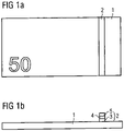
- a bank note with a substrate 1 is shown as a document of value.
- the denomination "50" is printed on the substrate 1 .
- the substrate 1 of the document of value consists of paper or a paper-like material and has a correspondingly high ink acceptance capacity and good printability for an in Figure 1a not shown, further imprint.
- a security element 2 for example an optical film element, is arranged on the substrate 1, which is a transfer element in the embodiment shown.
- the security element 2 comprises an adhesive layer 3 which comprises an activatable adhesive, for example a hot-melt adhesive.
- the central film component 4 of the optical film element 2 is fixed on the surface of the substrate 1 with the aid of the adhesive layer 3 .
- the optical film element 2 also comprises a transparent ink-accepting layer 5. Accordingly, the resulting surface of the banknote consists of the transparent ink-accepting layer 5 in the area of the optical film element 2 and in the remaining area from the surface of the substrate 1. Correspondingly, a high ink acceptance ability and thus a good printability is created over the entire value document, ie the ink acceptance ability of the substrate is not impaired by the application of the described optical film element designed as a transfer element. This configuration does not have all the features claimed, in particular the opaque ink acceptance layer.
- a second, not claimed exemplary embodiment of a document of value in the form of a banknote is shown.
- the document of value in turn comprises a substrate 1, which can consist of paper or a paper-like material or also of plastic or a foil.
- the substrate is typically opaque. In the case of a plastic banknote, however, the substrate is usually a transparent film.
- a first optical film element in the form of a window 6 (passage window) and a second optical film element in the form of a security thread 7 are arranged in the substrate 1 . Both window 6 and security thread 7 emerge in the substrate 1, whereby the common surface of substrate 1, window 6 and security thread 7 generally consists of different materials.
- a transparent ink acceptance layer 5 can be arranged directly on this common surface.
- the exemplary embodiment illustrated is a film composite banknote in which the substrate 1, as well as the window 6 and the security thread 7, are covered by a plastic layer 8, for example a PET film.
- the transparent ink acceptance layer 5 is directly on the plastic layer 8 arranged.
- the in Figure 2a banknote shown have further layers, not shown, such as adhesive or primer layers, which ensure, for example, sufficient adhesion of the various layers to one another.
- the transparent ink acceptance layer 5 thus forms a uniform surface of the document of value and thus creates a uniform and high ability to accept ink on the entire document of value.
- FIG. 2b illustrated in section embodiment of the invention differs from that in Figure 2a illustrated embodiment by an additional opaque ink-accepting layer 9.
- the transparent ink-accepting layer 5, as shown in the exemplary embodiment, can be arranged over the entire surface of the document of value or only in a first partial area above the common surface of substrate 1, window 6 and security thread 7, i.e. above the surface of the document of value, with the transparent ink acceptance layer 5 being arranged at least above the optical film elements, ie above the window 6 and the security thread 7 .
- the opaque ink acceptance layer 9 is not applied over the entire surface of the document of value.
- the surface of the value document is divided into one or more second sub-areas B, third sub-areas C and fourth sub-areas D.
- the second sub-areas B are completely outside the optical film elements, i.e. they do not overlap with the window 6 or security thread 7.
- the third sub-areas C correspond in the in Figure 2b illustrated embodiment the areas of the optical film elements, that is, they are arranged above window 6 and security thread 7.
- the third partial regions C have the dimensions of the optical film elements, but they can alternatively also cover a larger or smaller region.
- the fourth sub-areas D are transitional areas between the second sub-areas B and the third sub-areas C and directly adjoin the second sub-areas B and the third sub-areas C. Since the third partial areas C correspond to the areas of the optical elements, the fourth partial areas D form an outer edge area around the optical film elements.
- the fourth partial areas D preferably have a constant width.
- the opaque ink acceptance layer 9 is applied with a first, constant layer thickness.
- the layer thickness of the opaque ink acceptance layer 9 is zero, ie no opaque ink acceptance layer 9 is applied in the third partial areas C.
- the optical perceptibility of the optical film elements is not impaired by the presence of the opaque ink-accepting layer 9.
- the layer thickness of the opaque ink acceptance layer 9 decreases towards the third sub-areas C, which, as shown in the exemplary embodiment, can be continuous or can also be stepped.
- This decreasing course of the layer thickness of the opaque ink-accepting layer 9 in the fourth partial areas D creates a transitional area of the opaque ink-accepting layer 9 which, for example, prevents the occurrence of so-called glossy edges and the occurrence of the so-called Tesa effect.
- the layer thickness of the transparent ink acceptance layer 5 remains the same on the entire document of value and thus in the second B, third C and fourth D partial areas.
- the layer thickness of the transparent ink-receiving layer 5 in the third partial areas C and fourth partial areas D is increased in comparison with the layer thickness in the second partial areas B, so that the reduced layer thickness of the opaque ink-receiving layer 9 in these areas is compensated, so that the total layer thickness of opaque 9 and transparent 5 ink acceptance layer is constant and thus results in a completely flat surface of the document of value.
- the layer thickness of the transparent ink-accepting layer 5 in the second sub-areas B is zero and differs from zero only in the third sub-areas C and fourth sub-areas D.
- the transparent ink-accepting layer 5 thus fills in the gaps in the opaque ink-accepting layer 9, as a result of which a completely flat surface of the document of value is also created in this way.
- the transparent ink acceptance layer 5 is arranged above the opaque ink acceptance layer 9, ie the transparent ink acceptance layer 5 is applied as the opaque ink acceptance layer 9 in a later method step.
- the transparent ink-acceptance layer 5 is applied to the document of value in an earlier method step than the opaque ink-acceptance layer 9 , as a result of which the transparent ink-acceptance layer 5 lies below the opaque ink-acceptance layer 9 . In this case, too, it is possible to provide a completely flat surface of the document of value.
- the transparent ink acceptance layer 5 is arranged over the entire surface of the document of value and has an increased layer thickness in the third partial areas C and fourth partial areas D, such that the total layer thickness of the opaque 9 and transparent 5 ink acceptance layer remains the same.
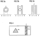
- Figure 3a is that in the Figures 2a to 2f shown window 6 shown in plan view. It has a circular shape and the third partial area C is arranged exactly above the window 6 and is therefore itself circular.
- the fourth sub-area D forms a ring of constant width around the third sub-area C, with the fourth sub-area D directly adjoining the third sub-area C.
- the second sub-area B directly follows the fourth sub-area D.
- the layer thickness of the opaque ink acceptance layer 9 shows a gradual progression in the radial direction, starting from the center of the circular window 6 in an annular area, which directly adjoins the window 6 in the radial direction to the outside.
- the third sub-area C can also form an area that deviates from the area of the optical film element, as is exemplified in Figure 3b is shown, where the third partial area C is a strip-shaped area in which the circular window 6 comes to rest completely.
- the fourth sub-areas D and second sub-areas B form further strip-shaped areas that directly adjoin.
- Such a strip-shaped third subregion C is particularly suitable for elongate optical film elements, such as those already described in FIGS Figures 2a to 2f shown security thread 7.
- the third sub-area C is wider than the security thread 7, with the fourth sub-areas D adjoining the third sub-area C as further strip-shaped areas, and the second sub-areas B directly adjoining them.
- the configuration of the third partial areas C, the fourth partial areas D and the second partial areas B can thus be adapted to the application method of the opaque and the transparent ink acceptance layer. These can be applied using common printing methods such as gravure printing, screen printing or flexographic printing, but also using coating methods in which the transparent and/or opaque ink-receiving layer is poured or sprayed onto the surface or is applied with rollers.
- One like in the Figures 3b and 3c The illustrated strip-shaped configuration of the third C, fourth D and second B partial areas is particularly suitable when the opaque and/or transparent ink acceptance layer is applied to the document of value with the aid of pressure rollers.
- a transparent ink-receiving layer 5 is arranged over an optical film element 2, which can be designed as a transfer element, and which has different configurations in the sub-areas 5a and 5b.
- the sub-areas 5a and 5b cannot be recognized by an observer.
- the configurations of the transparent ink acceptance layer 5 in the subregions 5a and 5b differ in their ink acceptance behavior.
- the further imprint applied in the sub-areas 5a and 5b appears with different brilliance, for example.
- an additional substructure formed by the subregions 5a and 5b can be created in the transparent ink acceptance layer, which only becomes recognizable after overprinting with a further print.
- the configurations of the transparent ink-accepting layer in the sub-areas 5a and 5b can also differ in other properties.
- effect pigments can be provided in the transparent ink-accepting layer 5 in one of the two sub-areas, as a result of which the sub-areas can only be distinguished when viewed from a predetermined viewing direction.
- the transparent ink acceptance layer can differ in its embossing behavior in the sub-areas 5a and 5b, as a result of which the different sub-areas 5a and 5b only become recognizable after the document of value has been embossed.
- the sub-areas 5a and 5b can form a substructure that conveys information to the viewer, for example a motif or a graphic or alphanumeric symbol.
- the opaque ink-accepting layer 9 can also have a sub-area 9a in which the opaque ink-accepting layer has a configuration that results in ink-acceptance behavior that differs from the remaining area of the opaque ink-acceptance layer 9, or in a different embossing behavior.
- effect pigments can also be provided only in a subregion 9a of the opaque ink-accepting layer or effect pigments that differ in their composition and/or alignment from the effect pigments in the rest of the ink-acceptance layer.
- the opaque ink-accepting layer there is also the possibility of generating a transmitted-light behavior that differs from the rest of the opaque ink-accepting layer 9 by using, for example, different fillers in the subregion 9a. The sub-area 9a cannot then be seen in reflected light, but can be seen in transmitted light.
- the invention was described using security elements designed as optical film elements, which are formed on the basis of a film.
- security elements that have a polymer layer instead of a plastic film could also be used.
- the security element can also be a feature produced by printing, for example a microprint.
Description
Die Erfindung betrifft ein Sicherheitselement zur Herstellung von Wertdokumenten sowie ein Wertdokument umfassend ein solches Sicherheitselement.The invention relates to a security element for the production of documents of value and a document of value comprising such a security element.
Wertdokumente im Sinne der vorliegenden Erfindung sind beispielsweise Banknoten, Aktien, Anleihen, Urkunden, Gutscheine, Schecks, Lotteriescheine, hochwertige Eintrittskarten, Pässe, Ausweise, Kreditkarten und andere flächige Wertgegenstände. Solche flächigen Wertgegenstände können beispielsweise auch Verpackungen für gegebenenfalls hochwertige Produkte sein. Der Begriff Wertdokument umfasst im Sinne der vorliegenden Erfindung auch alle Vorstufen von fertig gestellten Wertdokumenten, die beispielsweise noch nicht umlauffähig sind, wie unter anderem Sicherheitspapier, Folie oder Folienverbunde. Ein solches Wertdokument kann auch nur ein Teil in einem Wertgegenstand sein.Documents of value within the meaning of the present invention are, for example, banknotes, stocks, bonds, certificates, vouchers, checks, lottery tickets, high-quality entry tickets, passports, identity cards, credit cards and other flat objects of value. Such flat objects of value can also be, for example, packaging for possibly high-value products. In the context of the present invention, the term document of value also includes all preliminary stages of finished documents of value which, for example, are not yet fit for circulation, such as security paper, film or film composites, among others. Such a value document can also only be a part of a valuable object.
Derartige Wertdokumente werden aus gestalterischen Gründen oder aus Sicherheitsgründen mit Sicherheitselementen versehen, die allein durch ihr Vorhandensein oder ihre Ausgestaltung eine Prüfung der Echtheit der Wertdokumente gestatten und zugleich als Schutz vor unerlaubter Reproduktion dienen. Ein Sicherheitselement im Sinne der vorliegenden Erfindung kann z.B. ein Fenster bzw. Durchsichtsfenster, das z.B. durch eine transparente Folie gebildet ist, ein Sicherheitsfaden, ein drucktechnisch erzeugtes Merkmal wie z.B. ein Mikrodruck, ein Folienstreifen, ein Patch oder ein Etikett sein. Ein Sicherheitselement, insbesondere ein Sicherheitselement in Form eines Sicherheitsfadens oder eines Folienstreifens, kann als optisch variables Sicherheitselement ausgebildet sein, wobei im Sinne der vorliegenden Erfindung unter einem optisch variablen Sicherheitselement ein optisches Element verstanden wird, dessen bei einem Betrachter erzeugter visueller Eindruck von der Betrachtungsrichtung abhängt, das heißt dem Blickwinkel des Betrachters auf das optische Element und gegebenenfalls auch von der Einfallsrichtung eines Beleuchtungs-Lichtstrahles. Beispiele solcher optisch variabler Sicherheitselemente sind Beugungsstrukturen, die insbesondere durch Rekonstruktion von optisch wahrnehmbaren Mustern einen Betrachtungswinkel-abhängigen visuellen Eindruck erzeugen, wie beispielsweise Präge-oder Volumenhologramme und sonstige Kinegramme, wie achromatische matte Strukturen. Ein weiteres Beispiel solcher optisch variablen Elemente sind optische Elemente, die einen sogenannten Farbkippeffekt zeigen, wie beispielsweise ein- oder mehrlagige Dünnschicht-Interferenzschichten oder Flüssigkristallschichten, welche jeweils als durchgängige Schicht oder in Pigmentform (sogenannte Effektpigmente wie beispielsweise Iriodine) vorliegen können. Weitere Beispiele sind Linsen- oder Mikrospiegelstrukturen innerhalb eines optisch variablen Sicherheitselements. Solchen optischen Elementen ist gemeinsam, dass sie üblicherweise auf Basis einer Polymerschicht, z.B. einer Kunststofffolie, aufgebaut sind oder zumindest eine Polymerschicht als Deck- oder Schutzschicht umfassen. Im Sinne der vorliegenden Erfindung werden solche Elemente allgemein als Sicherheitselemente bezeichnet. Im speziellen Fall, dass das optische Element auf Basis einer Kunststofffolie aufgebaut ist, kann das Element als optisches Folienelement bezeichnet werden.For design reasons or for security reasons, such documents of value are provided with security elements which, merely by virtue of their presence or design, allow the authenticity of the documents of value to be checked and at the same time serve as protection against unauthorized reproduction. A security element within the meaning of the present invention can be, for example, a window or see-through window formed by a transparent film, a security thread, a feature produced by printing such as a microprint, a film strip, a patch or a label. A security element, in particular a security element in the form of a security thread or a film strip, can be embodied as an optically variable security element, with an optically variable security element being understood within the meaning of the present invention as an optical element whose visual impression produced by an observer depends on the viewing direction , that is, the viewing angle of the viewer onto the optical element and possibly also from the direction of incidence of an illuminating light beam. Examples of such optically variable security elements are diffraction structures which produce a viewing angle-dependent visual impression, in particular by reconstructing optically perceptible patterns, such as embossed or volume holograms and other kinegrams, such as achromatic matt structures. Another example of such optically variable elements are optical elements that show a so-called color shift effect, such as single- or multi-layer thin-film interference layers or liquid crystal layers, each of which can be present as a continuous layer or in pigment form (so-called effect pigments such as Iriodine). Further examples are lens or micromirror structures within an optically variable security element. A common feature of such optical elements is that they are usually constructed on the basis of a polymer layer, e.g. a plastic film, or at least comprise a polymer layer as a cover or protective layer. Within the meaning of the present invention, such elements are generally referred to as security elements. In the special case that the optical element is based on a plastic film, the element can be referred to as an optical film element.
Zur Erhöhung der Fälschungssicherheit, das heißt um eine Nachahmung zu erschweren, eine Überprüfung der Echtheit zu erleichtern oder als zusätzliches Gestaltungselement ist es wünschenswert, solche Sicherheitselemente oder Wertdokumente, die solche Sicherheitselemente umfassen, mit einem weiteren Aufdruck zusätzlich zu einem gegebenenfalls bereits aufgebrachten Aufdruck zu überdrucken. Jedoch ist die Farbannahme beim Überdrucken solcher Sicherheitselemente in der Regel nicht zufriedenstellend. Daher ist es bekannt, auf solchen Sicherheitselementen Druck- oder Farbannahmeschichten (im Folgenden der Einfachheit halber als Farbannahmeschichten bezeichnet) vorzusehen. Die für solche Sicherheitselemente geeigneten Farbannahmeschichten sind jedoch bei den notwendigen Schichtdicken oder infolge von Füllstoffen opak oder haben zumindest eine unerwünschte trübende Wirkung. Dadurch wird die visuelle Wahrnehmbarkeit oder die maschinelle Detektierbarkeit des Sicherheitselements negativ beeinflusst. Beispielsweise ist dann eine gute, ungestörte Durchsicht durch ein Fenster nicht mehr möglich. Handelt es sich bei dem Sicherheitselement um ein optisch variables Element, so kann dessen optisch variabler Effekt beeinträchtigt oder vollständig unterbunden werden.To increase security against counterfeiting, that is, to counterfeit make it more difficult to facilitate verification of authenticity or as an additional design element, it is desirable to overprint such security elements or documents of value which comprise such security elements with a further imprint in addition to an imprint that may already have been applied. However, the acceptance of ink when such security elements are overprinted is generally unsatisfactory. It is therefore known to provide printing or ink acceptance layers (hereinafter referred to as ink acceptance layers for the sake of simplicity) on such security elements. However, the ink acceptance layers suitable for such security elements are opaque at the necessary layer thicknesses or as a result of fillers or at least have an undesirable clouding effect. As a result, the visual perceptibility or machine detectability of the security element is adversely affected. For example, a good, undisturbed view through a window is then no longer possible. If the security element is an optically variable element, its optically variable effect can be impaired or prevented completely.
Eine Maßnahme dagegen wäre es, die Farbannahmeschicht mit einer verringerten Schichtdicke oder mit einem solchen Füllstoffgehalt vorzusehen, so dass die Opazität und/ oder die trübende Wirkung der Farbannahmeschicht reduziert wird, um so eine verbesserte Wahrnehmbarkeit eines Sicherheitselements zu gewährleisten. Dies hat jedoch den Nachteil, dass sich dadurch die Haftung und Trocknung der Druckfarbe des aufzubringenden weiteren Aufdrucks verschlechtert. Besteht die Anforderung einer guten Farbannahme, muss eine mehr oder weniger stark ausgeprägte Trübung oberhalb des Sicherheitselementes hingenommen werden. Besteht dagegen die Anforderung, beispielsweise ein klares Durchsichtsfenster herzustellen, so ist eine befriedigende Farbannahme der Druckfarbe des weiteren Aufdrucks auf dem Fenster bislang nicht möglich.One countermeasure would be to provide the ink acceptance layer with a reduced layer thickness or with such a filler content that the opacity and/or the clouding effect of the ink acceptance layer is reduced in order to ensure improved perceptibility of a security element. However, this has the disadvantage that the adhesion and drying of the printing ink of the further imprint to be applied deteriorates. If good ink acceptance is required, a more or less pronounced haze above the security element must be accepted. If, on the other hand, there is a requirement to produce a clear see-through window, for example, satisfactory ink trapping of the printing ink of the additional print on the window has hitherto not been possible.
Aufgabe der vorliegenden Erfindung ist es daher, ein Sicherheitselement, z.B. ein optisches Folienelement, für die Herstellung von Wertdokumenten anzugeben, das eine gute Farbannahme, Haftung und Trocknung einer Druckfarbe eines aufzubringenden weiteren Aufdrucks gestattet, ohne dabei eine Mattierung oder Trübung des Sicherheitselements zu verursachen. Es ist weiterhin Aufgabe der Erfindung, ein Wertdokument mit einem solchen Sicherheitselement anzugeben.The object of the present invention is therefore to specify a security element, e.g. an optical film element, for the production of documents of value, which allows good ink acceptance, adhesion and drying of an ink of a further imprint to be applied, without causing the security element to become matt or cloudy. It is also the object of the invention to specify a document of value with such a security element.
Diese Aufgabe wird durch ein Sicherheitselement sowie ein Wertdokument mit den Merkmalen der unabhängigen Ansprüche gelöst. Die abhängigen Ansprüche betreffen bevorzugte Ausgestaltungen und Weiterbildungen der Erfindung.This object is achieved by a security element and a document of value having the features of the independent claims. The dependent claims relate to preferred configurations and developments of the invention.
Farbannahmeschichten haben die Aufgabe, die Farbannahme, das heißt das Wegschlagen der Druckfarbe eines weiteren Aufdrucks oder von bestimmten Inhaltsstoffen solcher Druckfarben, wie Ölen, und somit die Haftung und Trocknung der Druckfarbe des weiteren Aufdrucks zu gewährleisten. Im Sinne der vorliegenden Erfindung werden unter dem Begriff Farbannahmeschicht auch Schichten verstanden, die eine verbesserte Haftung auf einer Oberfläche, insbesondere auf eine Polymer-, Kunststoff- oder Folienoberfläche, vermitteln. Die Farbannahmeschicht kann einschichtig oder mehrschichtig, das heißt aus mehreren Teilschichten aufgebaut sein, wobei die einzelnen Schichten jeweils homogen sind. Beispielsweise vermittelt eine gegebenenfalls direkt auf der Oberfläche des Sicherheitselements angeordnete erste Teilschicht der Farbannahmeschicht vornehmlich eine erhöhte Haftung einer weiteren Teilschicht der Farbannahmeschicht auf dem Sicherheitselement, während die weitere Teilschicht vornehmlich die Farbannahmefähigkeit der Druckfarbe eines weiteren Aufdrucks gewährleistet. Dabei wird die direkt auf der Oberfläche des Sicherheitselementes angeordnete, eine Klebefähigkeit aufweisende erste Teilschicht auch als Primer- oder Klebstoffschicht bezeichnet.The task of ink trapping layers is to ensure ink trapping, i.e. absorption of the printing ink from another imprint or certain ingredients of such printing inks, such as oils, and thus adhesion and drying of the printing ink in the further imprint. For the purposes of the present invention, the term ink acceptance layer also includes layers understood, which impart improved adhesion to a surface, in particular to a polymer, plastic or film surface. The ink-receiving layer can have one or more layers, ie it can be made up of several sub-layers, with the individual layers being homogeneous in each case. For example, a first sub-layer of the ink-receptive layer that is optionally arranged directly on the surface of the security element primarily provides increased adhesion of a further sub-layer of the ink-receptive layer on the security element, while the further sub-layer primarily ensures the ink receptivity of the printing ink of a further imprint. The first partial layer which is arranged directly on the surface of the security element and has adhesive properties is also referred to as a primer or adhesive layer.
Erfindungsgemäß ist die transparente Farbannahmeschicht oberhalb einer ersten Oberfläche des Sicherheitselementes angeordnet, das heißt die transparente Farbannahmeschicht ist z.B. entweder direkt auf eine Folie oder Polymer- bzw. Kunststoffschicht des Sicherheitselements appliziert oder durch eine oder mehrere weitere, vorzugsweise transparente Zwischenschichten davon getrennt. Beim Bedrucken des Sicherheitselements mit einem weiteren Aufdruck bildet die transparente Farbannahmeschicht vorteilhafterweise die oberste Schicht und stellt somit die Farbannahme, die Haftung und die Trocknung der Druckfarbe des weiteren Aufdrucks sicher. Der weitere Aufdruck kann dabei mit Hilfe eines Offset-Verfahrens, eines Tiefdruckverfahrens oder eines anderen geeigneten Druckverfahrens aufgebracht werden. Dabei kann es sich um einen Untergrunddruck handeln.According to the invention, the transparent ink-accepting layer is arranged above a first surface of the security element, i.e. the transparent ink-accepting layer is e.g. either applied directly to a foil or polymer or plastic layer of the security element or separated from it by one or more further, preferably transparent intermediate layers. When the security element is printed with a further imprint, the transparent ink acceptance layer advantageously forms the uppermost layer and thus ensures ink acceptance, adhesion and drying of the printing ink of the further imprint. The further imprint can be applied using an offset process, a gravure printing process or another suitable printing process. This can be a background pressure.
Die erfindungsgemäße Verwendung einer transparenten Farbannahmeschicht ermöglicht zumindest vor dem Aufbringen eines weiteren Aufdrucks eine unbeeinträchtigte Wahrnehmung des Sicherheitselementes. Insbesondere entsteht keine Beeinträchtigung der Wahrnehmbarkeit durch eine Mattierung oder Trübung. Handelt es sich bei dem Sicherheitselement um ein einfaches Fenster oder Durchsichtsfenster, das z.B. auf Grundlage einer transparenten Folie gebildet ist, so ermöglicht die Verwendung der transparenten Farbannahmeschicht weiterhin eine klare Durchsicht durch das Fenster. Besteht das Sicherheitselement aus einem optisch variablen Sicherheitselement, so gestattet die transparente Farbannahmeschicht eine Wahrnehmung eines unbeeinträchtigten optisch variablen Effekts.The use according to the invention of a transparent ink-receptive layer enables the security element to be perceived without impairment, at least before a further imprint is applied. In particular, there is no impairment of perceptibility due to matting or clouding. If the security element is a simple window or see-through window, which is formed e.g. on the basis of a transparent film, the use of the transparent ink-receptive layer also enables a clear view through the window. If the security element consists of an optically variable security element, the transparent ink-accepting layer allows an unimpaired optically variable effect to be perceived.
Die erfindungsgemäße transparente Farbannahmeschicht umfasst zumindest einen Füllstoff und ein Bindemittel.The transparent ink-accepting layer according to the invention comprises at least one filler and one binder.
Als Füllstoff wird Böhmit, pseudo-Böhmit, Zeolith, Al2O3 oder Kieselgel oder ein Gemisch von diesen Stoffen verwendet. Im Hinblick auf die Transparenz der transparenten Farbannahmeschicht weisen diese Füllstoffe vorzugsweise eine Partikelgröße in einem Bereich von 1 nm bis 1 µm auf, wobei der Bereich von 5 nm bis 200 nm besonders bevorzugt wird. Die Verwendung von Böhmit oder Pseudo-Böhmit wird bevorzugt. Unter Böhmit versteht man laut "
Als Bindemittel werden Polyvinylalkohol, modifizierter Polyvinylalkohol, Polyurethandispersionen, Acrylatdispersionen, sowie Derivate oder Mischungen derselben verwendet. Vorzugsweise liegt das Füllstoff-zu-Bindemittel-Verhältnis zwischen 6:1 und 30:1, wobei sich das genannte Verhältnis auf die Masse bezieht. Damit umfasst die transparente Farbannahmeschicht deutlich mehr Füllstoff als Bindemittel. Das Füllstoff-zu-Bindemittel-Verhältnis kann beispielsweise 6:1, 8:1, 10:1,12:1, 15:1, 20:1, 25:1 oder 30:1 betragen, wobei jedes der genannten Verhältnisse eine Unter- oder Obergrenze des oben genannten Bereichs darstellen kann.Polyvinyl alcohol, modified polyvinyl alcohol, polyurethane dispersions, acrylate dispersions, and derivatives or mixtures thereof are used as binders. Preferably, the filler to binder ratio is between 6:1 and 30:1, said ratio being by mass. The transparent ink-accepting layer thus comprises significantly more filler than binder. The filler-to-binder ratio may be, for example, 6:1, 8:1, 10:1, 12:1, 15:1, 20:1, 25:1, or 30:1, each of said ratios being a sub - or upper limit of the above range.
Neben dem genannten Füllstoff und Bindemittel umfasst die Farbannahmeschicht vorzugsweise einen Vernetzer, insbesondere aus der Stoffklasse Isocyanat, Aziridin, Carbodiimid oder Glycidether. Weiterhin kann die transparente Farbannahmeschicht weitere Zusatzstoffe wie etwa Entlüfter oder einprotonige Säuren umfassen.In addition to the filler and binder mentioned, the ink acceptance layer preferably comprises a crosslinking agent, in particular from the class of isocyanate, aziridine, carbodiimide or glycidyl ether. Furthermore, the transparent ink-accepting layer can include other additives such as deaerators or monoprotic acids.
Eine derart aufgebaute Farbannahmeschicht zeichnet sich durch eine gute Haftung auf Kunststoffschichten, insbesondere Kunststofffolien, aus und stellt weiterhin eine gute Farbannahmefähigkeit der aufzubringenden Druckfarbe des weiteren Aufdrucks sowie deren Trocknung und Haftung sicher. Diese Rezeptur kann daher auch als Ausgangspunkt zur Entwicklung von nicht-transparenten Farbannahmeschichten verwendet werden. Dazu werden der Rezeptur der Farbannahmeschicht weitere Zusatzstoffe, wie beispielsweise Pigmente, zugegeben, die die gewünschte Eigenschaft erzeugen. Dies können beispielsweise Pigmente wie TiO2, BaSO4, CaCO3, Kieselsäuren, oder Hohlkugelpigmente auf Polymerbasis wie z.B. "ROPAQUE" der Firma Rohm & Haas sein oder auch Effektpigmente, die einen Perlglanz oder einen metallischen Glanz erzeugen, Interferenzpigmente, Flüssigkristallpigmente, thermochrome oder magnetische Pigmente, oder Pigmente, die eine Phosphoreszenz oder Fluoreszenz erzeugen oder eine antistatische Wirkung aufweisen, sein. Weist eine solche Farbannahmeschicht aufgrund ihrer Zusatzstoffe beispielsweise eine hohe Opazität auf, empfiehlt es sich, gegebenenfalls eine gewünschte Basisfarbe des Sicherheitselementes oder eines Substrats über die Farbannahmeschicht zu realisieren.An ink acceptance layer constructed in this way is characterized by good adhesion to plastic layers, in particular plastic foils, and also ensures good ink acceptance of the printing ink to be applied in the further imprint and its drying and adhesion. This recipe can therefore also be used as a starting point for the development of non-transparent ink acceptance layers. For this purpose, further additives, such as pigments, are added to the formulation of the ink acceptance layer, which produce the desired property. These can be, for example, pigments such as TiO 2 , BaSO 4 , CaCO 3 , silica, or polymer-based hollow sphere pigments such as "ROPAQUE" from Rohm & Haas or effect pigments that produce a pearlescent or metallic luster, interference pigments, liquid crystal pigments, thermochromic or magnetic pigments, or pigments producing phosphorescence or fluorescence or having an antistatic effect. If such an ink-receptive layer has, for example, a high opacity due to its additives, it is advisable to implement a desired base color of the security element or a substrate via the ink-receptive layer.
Die Haftung der erfindungsgemäßen Farbannahmeschicht auf Kunststoffschichten, insbesondere Kunststofffolien, kann mittels einer als Haftvermittler dienenden Primer-Schicht verbessert werden.The adhesion of the ink acceptance layer according to the invention to plastic layers, in particular plastic films, can be improved by means of a primer layer serving as an adhesion promoter.
In einer bevorzugten Ausgestaltung des erfindungsgemäßen Sicherheitselements ist dieses als Durchsichtsfenster bzw. Fenster, drucktechnisch erzeugtes Merkmal, Sicherheitsfaden, Folienstreifen, Patch oder Etikett ausgebildet und die transparente Farbannahmeschicht ist vollflächig aufgebracht. Das Sicherheitselement umfasst weiter bevorzugt eine Polymerschicht, z.B. eine Kunststofffolie, auf der die transparente Farbannahmeschicht aufgebracht ist. Ein solches Sicherheitselement kann direkt auf einem zu sichernden Wertdokument erzeugt werden oder auf einem separaten Träger als Transferelement vorbereitet werden. Ein solcher separater Träger weist bevorzugt ein Kunststoff- bzw. Polymermaterial auf und kann beispielsweise ein Folienmaterial, insbesondere ein Transfermaterial, sein oder aufweisen. Für das Folienmaterial kommen dabei Kunststoffe wie PET (Polyethylenterephthalat), PBT (Polybutylenterephthalat), PEN (Polyethylennaphthalat), PP (Polypropylen), PA (Polyamid) und PE (Polyethylen) in Betracht. Dieses Folienmaterial kann ferner monoaxial oder biaxial gereckt sein.In a preferred embodiment of the security element according to the invention, this is designed as a see-through window or window, feature produced by printing, security thread, film strip, patch or label and the transparent ink acceptance layer is applied over the entire surface. The security element further preferably comprises a polymer layer, for example a plastic film, to which the transparent ink-accepting layer is applied. Such a security element can be produced directly on a document of value to be secured or can be prepared on a separate carrier as a transfer element. Such a separate carrier preferably has a plastic or polymer material and can be or have, for example, a foil material, in particular a transfer material. Plastics such as PET (polyethylene terephthalate), PBT (polybutylene terephthalate), PEN are used for the film material (polyethylene naphthalate), PP (polypropylene), PA (polyamide) and PE (polyethylene) into consideration. This film material can also be stretched monoaxially or biaxially.
Die Befestigung des Sicherheitselements auf einem zu sichernden Wertdokument erfolgt dabei mit Hilfe einer Klebstoffschicht, wobei hierfür vorzugsweise ein Heißschmelzkleber verwendet wird. Nach dem Transfer des Sicherheitselements auf ein zu sicherndes Wertdokument wird das Trägermaterial gegebenenfalls wieder abgezogen, so dass das Sicherheitselement auf dem zu sichernden Wertdokument verbleibt. Die transparente Farbannahmeschicht dient dabei als Trennschicht bzw. Release-Schicht.The security element is attached to a document of value to be secured with the aid of an adhesive layer, a hot-melt adhesive preferably being used for this purpose. After the security element has been transferred to a document of value to be secured, the carrier material is optionally removed again, so that the security element remains on the document of value to be secured. The transparent ink acceptance layer serves as a separating layer or release layer.
Auf bekannten Sicherheitselementen, insbesondere auf Transferelementen, wird häufig ein transparenter UV-Lack als Deck- und Schutzschicht verwendet. In der bevorzugten Ausgestaltung wird diese UV-Lackschicht entweder mit der transparenten Farbannahmeschicht überzogen oder durch die transparente Farbannahmeschicht ersetzt.A transparent UV lacquer is often used as a cover and protective layer on known security elements, in particular on transfer elements. In the preferred embodiment, this UV lacquer layer is either covered with the transparent ink-receptive layer or replaced by the transparent ink-receptive layer.
Die transparente Farbannahmeschicht bildet beim Bedrucken des Folienstreifens oder Transferelementes mit dem weiteren Aufdruck die oberste Schicht des Sicherheitselements, wodurch sich die Farbannahmefähigkeit für die Druckfarbe des weiteren Aufdrucks erhöht, da die transparente Farbannahmeschicht eine gegenüber dem bekannten transparenten UV-Lack verbesserte Druckfarbannahmefähigkeit aufweist.When the film strip or transfer element is printed with the further imprint, the transparent ink-receptive layer forms the uppermost layer of the security element, which increases the ink-receptiveness for the printing ink of the further imprint, since the transparent ink-receptive layer has improved ink-receptiveness compared to the known transparent UV lacquer.
In einer bevorzugten Ausgestaltung kann das Sicherheitselement als Patch oder Etikett ausgebildet sein und beispielsweise eine flächige Form mit vergleichbaren Längenabmessungen in allen Richtung aufweisen oder eine längliche Form beispielsweise in Form eines Streifens aufweisen, wie dies bei Sicherheitsfäden oder Folienstreifen, beispielsweise sogenannten LEAD-Streifen, der Fall ist. Ist ein solches Sicherheitselement als Transferelement mit einer gegebenenfalls transparenten Folie als Träger ausgebildet, so wird es auch als Folienelement, Folienpatch oder Folienstreifen bezeichnet.In a preferred embodiment, the security element can be designed as a patch or label and, for example, have a flat shape with comparable length dimensions in all directions or have an elongated shape, for example in the form of a strip, as is the case with security threads or film strips, for example so-called LEAD strips, the case is. If such a security element is designed as a transfer element with an optionally transparent film as the carrier, it is also referred to as a film element, film patch or film strip.
In der Erfindung umfasst ein Wertdokument ein Substrat sowie ein erfindungsgemäßes Sicherheitselement, das derart auf dem Substrat des Wertdokumentes angeordnet ist, dass die erste Oberfläche des Sicherheitselementes mit einer ersten Oberfläche des Substrats eine gemeinsame Oberfläche bildet. Dabei ist die transparente Farbannahmeschicht oberhalb der gemeinsamen Oberfläche entweder vollflächig oder zumindest in einem ersten Teilbereich der gemeinsamen Oberfläche angeordnet. Die transparente Farbannahmeschicht kann somit auch in einem Bereich außerhalb des Sicherheitselements angeordnet sein. Mit der Formulierung "außerhalb des Sicherheitselements" ist gemeint, dass die transparente Farbannahmeschicht bei der Betrachtung des Wertdokuments im Auflicht nicht oberhalb des Sicherheitselements angeordnet ist.According to the invention, a document of value comprises a substrate and a security element according to the invention, which is arranged on the substrate of the document of value in such a way that the first surface of the security element forms a common surface with a first surface of the substrate. In this case, the transparent ink acceptance layer is arranged above the common surface either over the entire area or at least in a first partial area of the common surface. The transparent ink-accepting layer can thus also be arranged in an area outside of the security element. The wording "outside the security element" means that the transparent ink-accepting layer is not arranged above the security element when the document of value is viewed in incident light.
Als Substrat des Wertdokumentes können ein- oder mehrlagige Substrate verwendet werden. Im Fall von einlagigen Substraten kommt jede Art von Papier oder Papier-artigem Material in Betracht, insbesondere Baumwoll-Velin-Papier. Es kann auch Papier eingesetzt werden, welches einen gewissen Anteil x eines Polymermaterials im Bereich von 0 bis 100 Gew.-% enthält. Weiterhin kann als Substrat eine Kunststoffschicht, beispielsweise eine Kunststofffolie, oder ein Folienverbund verwendet werden. Eine solche Folie kann zusätzlich monoaxial oder biaxial gereckt sein. Eine solche Reckung der Folie führt unter anderem dazu, dass sie polarisierende Eigenschaften erhält, die als Sicherheitsmerkmal in dem Wertdokument genutzt werden können.Single-layer or multi-layer substrates can be used as the substrate of the document of value. In the case of single-ply substrates, any type of paper or paper-like material can be used, in particular cotton vellum paper. Paper can also be used which contains a certain proportion x of a polymer material in the range from 0 to 100% by weight. Furthermore, as Substrate a plastic layer, such as a plastic film, or a composite film can be used. Such a film can additionally be stretched monoaxially or biaxially. Such a stretching of the film leads, among other things, to the fact that it acquires polarizing properties that can be used as a security feature in the document of value.
Als mehrlagiges Substrat kann ein mehrlagiger Verbund verwendet werden, der beispielsweise eine Schicht aus Papier oder einem Papier-artigen Material aufweist. Auf diese Schicht ist beispielsweise von beiden Seiten eine transparente Kunststoff- oder Polymerschicht aufkaschiert, wodurch ein solcher mehrlagiger Verbund eine außerordentlich große Stabilität und Haltbarkeit aufweist. Dabei werden Sicherheitspapiere mit Kunststoff- oder Polymerbeschichteten Papierschichten zur Herstellung von Folienverbundbanknoten verwendet. Umgekehrt kann der mehrlagige Verbund auch eine zentrale Schicht aus einem Kunststoff- oder Polymermaterial aufweisen, welche beidseitig mit jeweils einer Lage aus Papier oder einem Papier-artigen Material beschichtet ist. Als mehrlagiges Substratmaterial kann auch ein mehrschichtiges, papierfreies Komposit-Material eingesetzt werden.A multi-layer composite can be used as the multi-layer substrate, which has, for example, a layer of paper or a paper-like material. A transparent plastic or polymer layer is laminated onto this layer, for example on both sides, as a result of which such a multilayer composite has an extremely high level of stability and durability. Security papers with plastic or polymer-coated paper layers are used to produce foil composite banknotes. Conversely, the multi-layer composite can also have a central layer made of a plastic or polymer material, which is coated on both sides with a layer made of paper or a paper-like material. A multi-layer, paper-free composite material can also be used as the multi-layer substrate material.
Das Sicherheitselement kann auf der Oberfläche des Substrats angeordnet werden. Es kann jedoch auch innerhalb des Substrats angeordnet sein und beispielsweise nur bereichsweise an die Oberfläche des Substrats treten, wie dies bei Sicherheitsfäden wie Fenster- oder Pendel-Sicherheitsfäden der Fall ist. Das Sicherheitselement kann auch eine Aussparung in dem Substrat füllen, wie dies bei Fenstern, insbesondere Durchsichtsfenstern der Fall ist. Auch kann das Sicherheitselement im Falle eines aus mehreren Schichten bestehenden Verbundes, wie etwa einer Folienverbundbanknote, auch unterhalb einer transparenten Schicht, z.B. einer Kunststofffolie, angeordnet sein oder innerhalb der transparenten Schicht eingebettet sein.The security element can be arranged on the surface of the substrate. However, it can also be arranged within the substrate and, for example, only partially come to the surface of the substrate, as is the case with security threads such as window or pendulum security threads. The security element can also fill a gap in the substrate, as is the case with windows, in particular see-through windows. In the case of a composite consisting of several layers, such as a foil composite bank note, the security element can also be arranged underneath a transparent layer, e.g. a plastic foil, or embedded within the transparent layer.
Ein als Transferelement ausgebildetes Sicherheitselement mit einer vollflächigen transparenten Farbannahmeschicht eignet sich besonders zur Aufbringung auf einem Wertdokument, dessen Substratoberfläche aus Papier oder einem Papier-artigen Material besteht, insbesondere wenn die transparente Farbannahmeschicht derart realisiert ist, das sie die gleiche oder eine ähnliche Farbannahmefähigkeit wie die Papier- oder Papier-artige Substratoberfläche des Wertdokuments aufweist, da somit ein Wertdokument mit einem Sicherheitselement realisiert werden kann, welches ohne weitere Beschichtungsschritte notwendig zu machen, eine hohe Farbannahmefähigkeit auf seiner gesamten Oberfläche aufweist.A security element designed as a transfer element with a full-area transparent ink-accepting layer is particularly suitable for application to a document of value whose substrate surface consists of paper or a paper-like material, in particular if the transparent ink-accepting layer is implemented in such a way that it has the same or a similar ink-accepting ability as the Has paper or paper-like substrate surface of the document of value, since a document of value can thus be realized with a security element which, without making further coating steps necessary, has a high ability to accept ink over its entire surface.
Die transparente Farbannahmeschicht kann unmittelbar auf der gemeinsamen Oberfläche von Sicherheitselement und Substrat angeordnet werden. In einer bevorzugten Ausgestaltung ist jedoch eine weitere transparente Schicht, beispielsweise eine Kunststofffolie, insbesondere eine PET-Folie bzw. Polyesterfolie, zwischen der gemeinsamen Oberfläche und der transparenten Farbannahmeschicht angeordnet. Dabei bildet die transparente Schicht beispielsweise eine Deck- oder Schutzschicht für das Sicherheitselement und das Substrat. Die transparente Farbannahmeschicht stellt dann die Bedruckbarkeit mit der Druckfarbe eines weiteren Aufdrucks sicher. Bevorzugt ist die weitere transparente Schicht unmittelbar auf der gemeinsamen Oberfläche angeordnet und/ oder die transparente Farbannahmeschicht unmittelbar auf der weiteren transparenten Schicht, z.B. einer Kunststofffolie, angeordnet.The transparent ink-accepting layer can be arranged directly on the common surface of the security element and the substrate. In a preferred embodiment, however, a further transparent layer, for example a plastic film, in particular a PET film or polyester film, is arranged between the common surface and the transparent ink acceptance layer. In this case, the transparent layer forms, for example, a cover or protective layer for the security element and the substrate. The transparent ink-receiving layer then ensures printability with the printing ink of a further imprint. The further transparent layer is preferably arranged directly on the common surface and/or the transparent ink-receiving layer is arranged directly on the further transparent layer, eg a plastic film.
Erfindungsgemäß ist oberhalb der gemeinsamen Oberfläche neben der transparenten Farbannahmeschicht zusätzlich eine opake Farbannahmeschicht angeordnet. In einem zweiten Teilbereich der gemeinsamen Oberfläche, welcher außerhalb, das heißt bei der Betrachtung des Wertdokuments im Auflicht nicht oberhalb, des Sicherheitselements liegt, weist die opake Farbannahmeschicht eine erste, vorzugsweise gleich bleibende Schichtdicke auf. Ein dritter Teilbereich der gemeinsamen Oberfläche befindet sich oberhalb des Sicherheitselements und ist vorzugsweise durch die Ausdehnung des Sicherheitselements definiert. In diesem dritten Teilbereich weist die opake Farbannahmeschicht eine Aussparung auf, das heißt eine Schichtdicke von null oder zumindest eine gegenüber der ersten Schichtdicke verringerte Schichtdicke. Dadurch ist das Sicherheitselement vollständig nur von der transparenten Farbannahmeschicht überzogen. Die opake Farbannahmeschicht ist nur in Bereichen außerhalb des Sicherheitselements angeordnet.According to the invention, an opaque ink-accepting layer is additionally arranged above the common surface in addition to the transparent ink-accepting layer. In a second partial area of the common surface, which lies outside of the security element, ie not above the security element when the document of value is viewed in incident light, the opaque ink-accepting layer has a first, preferably constant, layer thickness. A third portion of the common surface is located above the security element and is preferably defined by the extent of the security element. In this third sub-area, the opaque ink-accepting layer has a recess, ie a layer thickness of zero or at least a layer thickness that is reduced compared to the first layer thickness. As a result, the security element is completely covered only by the transparent ink-accepting layer. The opaque ink-accepting layer is only arranged in areas outside of the security element.
Eine derartige Ausgestaltung gestattet eine Anordnung einer opaken Farbannahmeschicht auf dem Wertdokument, ohne die Wahrnehmbarkeit des Sicherheitselementes zu beeinträchtigen, wobei gleichzeitig eine gute Bedruckbarkeit des Wertdokumentes auch oberhalb des Sicherheitselements gewährleistet ist.Such a configuration allows an opaque ink-accepting layer to be arranged on the document of value without impairing the perceptibility of the security element, while at the same time good printability of the document of value is also ensured above the security element.
In den Randbereichen der opaken Farbannahmeschicht, beispielsweise dort, wo die opake Farbannahmeschicht an die transparente Farbannahmeschicht unmittelbar angrenzt, kann es jedoch zu unerwünschten Glanzkanten (Tesaeffekt) kommen. Solche Glanzkanten stehen einem gewünschten einheitlichen Erscheinungsbild der Oberfläche des Wertdokumentes entgegen. In einer bevorzugten Ausgestaltung nimmt daher die Schichtdicke der opaken Farbannahmeschicht innerhalb des dritten Teilbereiches und/ oder in einem vierten Teilbereich ausgehend von der ersten Schichtdicke der opaken Farbannahmeschicht in dem zweiten Teilbereich treppenförmig oder stufenlos ab, vorzugsweise bis auf null oder etwa null. Dieser abnehmende Verlauf zeigt vorzugsweise einen konstanten Gradienten. Der vierte Teilbereich der gemeinsamen Oberfläche liegt dabei zwischen dem zweiten und dem dritten Teilbereich und grenzt vorzugsweise unmittelbar an den dritten Teilbereich und umgibt diesen vollständig. Im einfachsten Fall definiert der dritte Teilbereich den Bereich des Sicherheitselements, wodurch der vierte Teilbereich einen Randbereich des Sicherheitselementes definiert, welcher außerhalb des Sicherheitselementes liegt und diesen unmittelbar umgibt. Dabei weist der vierte Teilbereich vorzugsweise eine konstante Breite auf. Die Schichtdicke der opaken Farbannahmeschicht nimmt im dritten und/oder vierten Teilbereich bis auf null oder etwa null ab. Besonders bevorzugt beträgt die Schichtdicke der opaken Farbannahmeschicht im gesamten dritten Teilbereich null und die Schichtdicke der opaken Farbannahmeschicht nimmt in dem vierten Teilbereich ausgehend von dem Randbereich zum zweiten Teilbereich bis hin zum Randbereich zum dritten Teilbereich von der ersten Schichtdicke auf null ab.In the edge regions of the opaque ink-accepting layer, for example where the opaque ink-accepting layer directly adjoins the transparent ink-accepting layer, however, undesired glossy edges (adhesive tape effect) can occur. Such shiny edges stand in the way of a desired uniform appearance of the surface of the document of value. In a preferred embodiment, the layer thickness of the opaque ink-accepting layer within the third partial area and/or in a fourth partial area decreases stepwise or continuously, starting from the first layer thickness of the opaque ink-accepting layer in the second partial area, preferably down to zero or approximately zero. This decreasing curve preferably shows a constant gradient. The fourth sub-area of the common surface lies between the second and the third sub-area and preferably borders directly on the third sub-area and completely surrounds it. In the simplest case, the third sub-area defines the area of the security element, as a result of which the fourth sub-area defines an edge area of the security element, which lies outside of the security element and immediately surrounds it. In this case, the fourth partial area preferably has a constant width. The layer thickness of the opaque ink-accepting layer decreases to zero or approximately zero in the third and/or fourth partial area. The layer thickness of the opaque ink acceptance layer is particularly preferably zero in the entire third partial area and the layer thickness of the opaque ink acceptance layer decreases from the first layer thickness to zero in the fourth partial area, starting from the edge area to the second partial area to the edge area to the third partial area.
Durch einen derartigen graduellen Verlauf der Schichtdicke der opaken Farbannahmeschicht ist der Randbereich der opaken Farbannahmeschicht nur noch geringfügig zu erkennen und störende Glanzkanten beispielsweise am Übergangsbereich zwischen opaker und transparenter Farbannahmeschicht werden vermieden.With such a gradual development of the layer thickness of the opaque ink-accepting layer, the edge area of the opaque ink-accepting layer can only be seen slightly and disruptive shiny edges, for example at the transition area between opaque and transparent ink-accepting layers, are avoided.
In einer weiteren bevorzugten Ausgestaltung ist die transparente Farbannahmeschicht innerhalb des zweiten, dritten und gegebenenfalls vierten Teilbereichs unterhalb oder oberhalb der opaken Farbannahmeschicht angeordnet, weist dort eine gleich bleibende Schichtdicke auf und ist vorzugsweise als zusammenhängende Schicht ausgebildet. Im einfachsten Fall ist dazu die transparente Farbannahmeschicht mit gleich bleibender Schichtdicke auf dem Wertdokument aufgetragen. Alternativ kann die transparente Farbannahmeschicht im dritten und gegebenenfalls vierten Teilbereich eine gegenüber dem zweiten Teilbereich erhöhte Schichtdicke aufweisen, um die reduzierte Schichtdicke der opaken Farbannahmeschicht in diesem Bereich vollständig oder zumindest teilweise auszugleichen. Besonders bevorzugt ist die Schichtdicke der transparenten Farbannahmeschicht dabei derart ausgestaltet, dass die Summe der Schichtdicken von transparenter und opaker Farbannahmeschicht im zweiten, dritten und gegebenenfalls vierten Teilbereich, vorzugsweise vollflächig auf der gesamten Oberfläche des Wertdokumentes, gleich bleibend ist. In diesem Fall weist die Schichtdicke der transparenten Farbannahmeschicht in dem dritten und/ oder vierten Teilbereich ausgehend von dem zweiten Teilbereich einen der opaken Farbannahmeschicht entsprechenden, in Richtung des dritten Teilbereichs treppenförmig oder stufenlos zunehmenden Verlauf, vorzugsweise mit einem konstanten Gradienten, auf. Besonders bevorzugt weist die transparente Farbannahmeschicht in dem dritten Teilbereich eine konstante Schichtdicke auf und zeigt nur in dem vierten Teilbereich eine unterschiedliche Schichtdicke.In a further preferred embodiment, the transparent ink-accepting layer is arranged within the second, third and possibly fourth partial area below or above the opaque ink-accepting layer, has a constant layer thickness there and is preferably formed as a coherent layer. In the simplest case, the transparent ink acceptance layer is applied to the document of value with a layer thickness that remains the same. Alternatively, the transparent ink-accepting layer in the third and optionally fourth partial area can have a layer thickness that is increased compared to the second partial area in order to completely or at least partially compensate for the reduced layer thickness of the opaque ink-accepting layer in this area. The layer thickness of the transparent ink-accepting layer is particularly preferably designed such that the sum of the layer thicknesses of the transparent and opaque ink-accepting layer in the second, third and possibly fourth partial area, preferably over the entire surface of the document of value, remains the same. In this case, the layer thickness of the transparent ink-receiving layer in the third and/or fourth sub-area, starting from the second sub-area, has a profile corresponding to the opaque ink-receiving layer, increasing stepwise or continuously in the direction of the third sub-area, preferably with a constant gradient. Particularly preferably, the transparent ink-accepting layer has a constant layer thickness in the third sub-area and has a different layer thickness only in the fourth sub-area.
Durch derartige Ausgestaltungen von opaker und transparenter Farbannahmeschicht auf dem Wertdokument wird eine vollständig ebene gemeinsame Oberfläche von opaker und transparenter Farbannahmeschicht geschaffen.Such configurations of the opaque and transparent ink-accepting layer on the document of value create a completely flat common surface of the opaque and transparent ink-accepting layer.
In einer weiteren bevorzugten Ausgestaltung ist die transparente Farbannahmeschicht nur innerhalb des dritten und gegebenenfalls vierten Teilbereichs angeordnet, das heißt die Schichtdicke der transparenten Farbannahmeschicht im zweiten Teilbereich beträgt null. Innerhalb des dritten und/ oder gegebenenfalls vierten Teilbereichs zeigt die Schichtdicke der transparenten Farbannahmeschicht ausgehend von der Schichtdicke null am Randbereich zum zweiten Teilbereich wiederum einen in Richtung des dritten Teilbereichs treppenförmig oder stufenlos zunehmenden Verlauf, vorzugsweise mit einem konstanten Gradienten, so dass die Summe der Schichtdicken von transparenter und opaker Farbannahmeschicht im zweiten, dritten und gegebenenfalls vierten Teilbereich, vorzugsweise vollflächig auf dem gesamten Wertdokument, gleich bleibend ist. Beträgt die Schichtdicke der opaken Farbannahmeschicht im dritten Teilbereich den Wert null, so ist die Schichtdicke der Farbannahmeschicht in dem dritten Teilbereich gleich bleibend und gleich der Schichtdicke der Farbannahmeschicht in dem zweiten Teilbereich.In a further preferred configuration, the transparent ink-accepting layer is arranged only within the third and optionally fourth partial area, ie the layer thickness of the transparent ink-accepting layer in the second partial area is zero. Within the third and/or possibly fourth sub-area, the layer thickness of the transparent ink-receiving layer, starting from the layer thickness zero at the edge area to the second sub-area, again shows a stair-like or continuously increasing course in the direction of the third sub-area, preferably with a constant gradient, so that the sum of the layer thicknesses of transparent and opaque ink-accepting layer in the second, third and optionally fourth partial area, preferably over the entire surface of the entire document of value, remains the same. If the layer thickness of the opaque ink-accepting layer in the third subarea is zero, then the layer thickness of the ink-accepting layer in the third subarea remains the same and is equal to the layer thickness of the ink-accepting layer in the second subarea.
Durch derartige Ausgestaltungen von opaker und transparenter Farbannahmeschicht auf dem Wertdokument wird eine vollständig ebene gemeinsame Oberfläche von opaker und transparenter Farbannahmeschicht geschaffen.Such configurations of the opaque and transparent ink-accepting layer on the document of value create a completely flat common surface of the opaque and transparent ink-accepting layer.
In einer weiteren bevorzugten Ausgestaltung des Wertdokumentes weist die transparente Farbannahmeschicht einen ersten und einen zweiten Unterbereich auf, wobei die transparente Farbannahmeschicht in dem ersten und zweiten Unterbereich eine erste und zweite Ausgestaltung besitzt, welche voneinander verschieden sind. Der Bereich, in dem die transparente Farbannahmeschicht aufgetragen ist, ist somit in wenigstens zwei Unterbereiche unterteilt, welche bevorzugt aneinandergrenzen. Die Ausgestaltung in den beiden Unterbereichen ist dabei derart, dass die beiden Unterbereiche zumindest bei Betrachtung aus einer vorbestimmten Betrachtungsrichtung und vorzugsweise bei Betrachtung aus allen Betrachtungsrichtungen einen optisch gleichen Eindruck bei einem Betrachter erzeugen, während sich beide Unterbereiche in einer technischen Eigenschaft unterscheiden. Dies kann beispielsweise das Farbannahmeverhalten bezüglich des aufzubringenden weiteren Aufdrucks oder das Verhalten bei Verprägung des Wertdokuments und/ oder des Sicherheitselements sein.In a further preferred embodiment of the document of value the transparent ink receptive layer has first and second subregions, the transparent ink receptive layer having first and second configurations in the first and second subregions that are different from each other. The area in which the transparent ink-receiving layer is applied is thus divided into at least two sub-areas, which preferably border one another. The configuration in the two sub-areas is such that the two sub-areas produce an optically identical impression on an observer, at least when viewed from a predetermined viewing direction and preferably when viewed from all viewing directions, while the two sub-areas differ in one technical property. This can be, for example, the ink acceptance behavior with regard to the further imprint to be applied or the behavior when the document of value and/or the security element is embossed.
Ebenso kann alternativ oder zusätzlich die opake Farbannahmeschicht einen ersten und einen zweiten Unterbereich aufweisen, wobei die opake Farbannahmeschicht in dem ersten und zweiten Unterbereich eine erste und zweite Ausgestaltung besitzt, welche voneinander verschieden sind. Der Bereich, in dem die opake Farbannahmeschicht aufgetragen ist, ist somit in wenigstens zwei Unterbereiche unterteilt, welche bevorzugt aneinandergrenzen. Die Ausgestaltung in den beiden Unterbereichen ist dabei derart, dass die beiden Unterbereiche zumindest bei Betrachtung aus einer vorbestimmten Betrachtungsrichtung und vorzugsweise bei Betrachtung aus allen Betrachtungsrichtungen einen optisch gleichen Eindruck bei einem Betrachter erzeugen, während sich beide Unterbereiche in einer technischen Eigenschaft unterscheiden. Dies kann beispielsweise das Farbannahmeverhalten bezüglich des aufzubringenden weiteren Aufdrucks oder das Verhalten bei Verprägung des Wertdokuments und/oder des Sicherheitselements sein.Likewise, alternatively or additionally, the opaque ink-accepting layer can have a first and a second sub-area, wherein the opaque ink-accepting layer has a first and second configuration in the first and second sub-area, which are different from one another. The area in which the opaque ink-accepting layer is applied is thus divided into at least two sub-areas, which preferably border one another. The configuration in the two sub-areas is such that the two sub-areas produce an optically identical impression on an observer, at least when viewed from a predetermined viewing direction and preferably when viewed from all viewing directions, while the two sub-areas differ in one technical property. This can be, for example, the ink acceptance behavior with regard to the further imprint to be applied or the behavior when the document of value and/or the security element is embossed.
Unmittelbar nach dem Aufbringen der opaken und/ oder transparenten Farbannahmeschicht sind die jeweils beiden Unterbereiche für einen Betrachter zumindest bei Betrachtung einer vorbestimmten Betrachtungsrichtung und vorzugsweise bei Betrachtung aus allen Betrachtungsrichtungen für einen Betrachter ununterscheidbar. Unterscheiden sich die jeweils beiden Unterbereiche beispielsweise in ihrem Farbannahmeverhalten bezüglich der Druckfarbe des aufzubringenden weiteren Aufdrucks, so sind die beiden Unterbereiche im unbedruckten Zustand, wie oben beschrieben, ununterscheidbar. Beim Aufbringen der Druckfarbe des weiteren Druckbildes auf die jeweils beiden Unterbereiche von transparenter oder opaker Farbannahmeschicht werden diese zumindest bei Betrachtung aus einer vorbestimmten Richtung vorzugsweise bei Betrachtung aus allen Betrachtungsrichtungen für einen Betrachter unterscheidbar, indem sie einen unterschiedlichen optischen Eindruck beim Betrachter erzeugen, beispielsweise eine unterschiedliche Farbbrillanz zeigen. Dabei ist es von Vorteil, wenn die Druckfarbe des weiteren Druckbildes als Untergrunddruck vollflächig auf die jeweils beiden Unterbereiche aufgebracht wird.Immediately after the application of the opaque and/or transparent ink-accepting layer, the respective two sub-areas are indistinguishable for an observer at least when viewing a predetermined viewing direction and preferably when viewing from all viewing directions for an observer. If the respective two sub-areas differ, for example, in their ink acceptance behavior with regard to the printing ink of the further imprint to be applied, then the two sub-areas are indistinguishable in the unprinted state, as described above. When the printing ink of the further printed image is applied to the two respective sub-areas of the transparent or opaque ink-receiving layer, these become distinguishable for an observer at least when viewed from a predetermined direction, preferably when viewed from all viewing directions, by creating a different visual impression for the observer, for example a different one show color brilliance. In this case, it is advantageous if the printing ink of the further printed image is applied over the entire surface of the respective two sub-areas as a background print.
Alternativ oder zusätzlich können sich die jeweils beiden Unterbereiche auch in ihrem Verhalten gegenüber einer Verprägung unterscheiden, das heißt sie weisen beispielsweise eine voneinander verschiedene mechanische Stabilität auf.Alternatively or additionally, the respective two sub-areas can also differ in their behavior towards embossing, that is to say they have mechanical stability that differs from one another, for example.
Die notwendige unterschiedliche Ausgestaltung der jeweils beiden Unterbereiche von opaker und/ oder transparenter Farbannahmeschicht können im Falle eines mehrschichtigen Aufbaus durch einen unterschiedlichen Schichtaufbau oder durch verschiedene Rezepturen für die Farbannahmeschichten in den jeweiligen Unterbereichen erreicht werden. Beispielsweise können in einem Unterbereich zusätzliche Pigmente in der Farbannahmeschicht vorgesehen sein, deren Vorhandensein nur bei Betrachtung in einer vorbestimmten Betrachtungsrichtung erkennbar ist, wie dies beispielsweise bei Effektpigmenten wie Interferenzpigmenten oder Flüssigkristallpigmenten der Fall ist, welche beispielsweise einen Farbkippeffekt zeigen. Alternativ können bei Verwendung solcher Effektpigmente auch die gleichen Rezepturen für die Farbannahmeschicht in beiden Unterbereichen verwendet werden, wobei die Ausrichtung der Effektpigmente in diesen Unterbereichen voneinander verschieden ausgebildet wird. Für die verschiedenen Unterbereiche einer opaken Farbannahmeschicht können auch das Transmissionsverhalten verändernde unterschiedliche Inhaltsstoffe verwendet werden, wodurch die beiden Unterbereiche der opaken Farbannahmeschicht im Auflicht einen identischen optischen Eindruck erzeugen, im Durchlicht jedoch voneinander unterscheidbar sind.The necessary different design of the two In the case of a multi-layer structure, sub-areas of opaque and/or transparent ink-receptive layers can be achieved by a different layer structure or by different formulations for the ink-receptive layers in the respective sub-areas. For example, additional pigments can be provided in the ink-accepting layer in a sub-area, the presence of which can only be recognized when viewed in a predetermined viewing direction, as is the case, for example, with effect pigments such as interference pigments or liquid-crystal pigments, which exhibit a color-shift effect, for example. Alternatively, when using such effect pigments, the same formulations can also be used for the ink acceptance layer in both sub-areas, with the effect pigments being oriented differently in these sub-areas. Different ingredients that change the transmission behavior can also be used for the various sub-areas of an opaque ink-accepting layer, as a result of which the two sub-areas of the opaque ink-accepting layer produce an identical optical impression in reflected light, but are distinguishable from one another in transmitted light.
In einer weiteren bevorzugten Ausgestaltung sind die jeweiligen Unterbereiche von opaker und/ oder transparenter Farbannahmeschicht derart angeordnet, dass sich für den Betrachter eine erkennbare Information ergibt, wenn diese Unterbereiche voneinander unterscheidbar sind. Die durch die beiden jeweiligen Unterbereiche gebildete Substruktur bildet beispielsweise ein Motiv oder ein graphisches oder alphanumerisches Zeichen.In a further preferred embodiment, the respective sub-areas of the opaque and/or transparent ink-receiving layer are arranged in such a way that the viewer receives recognizable information if these sub-areas can be distinguished from one another. The substructure formed by the two respective sub-areas forms, for example, a motif or a graphic or alphanumeric character.
Bei dem erfindungsgemäßen Sicherheitselement sowie dem erfindungsgemäßen Wertdokument kann die transparente Farbannahmeschicht zusätzlich mit einer Überlackierung versehen werden, durch die eine Mattierung und/oder eine Verlängerung der Lebensdauer und Umlauffähigkeit erreicht werden kann. Als Lackschicht eignet sich z.B. ein aus einer unteren und einer oberen Lackschicht bestehendes Lacksystem, das z.B. in der
Weitere Ausführungsbeispiele und Vorteile der Erfindung werden nachfolgend beispielhaft anhand der begleitenden
Im Einzelnen zeigen die Figuren:
-
Figur 1a
eine Banknote mit einem Sicherheitselement in Draufsicht; -
Figur 1b
einen Schnitt durch die Banknote ausFigur 1a ; -
Figur 2a bis 2f
Schnittansichten durch Ausführungsbeispiele; -
Figur 3a bis 3c
Draufsichten auf verschiedene Ausgestaltungen von Teilbereichen; und -
Figur 4 eine
Draufsicht auf ein weiteres Ausführungsbeispiel eines Wertdokumentes.
-
Figure 1a
a bank note with a security element in plan view; -
Figure 1b
make a cut through the banknoteFigure 1a ; -
Figure 2a to 2f
sectional views through exemplary embodiments; -
Figure 3a to 3c
Top views of different configurations of partial areas; and -
figure 4 one
Top view of a further exemplary embodiment of a document of value.
In den
In
Das in
In den zweiten Teilbereichen ist die opake Farbannahmeschicht 9 mit einer ersten, gleich bleibenden Schichtdicke aufgetragen. In den dritten Teilbereichen C beträgt die Schichtdicke der opaken Farbannahmeschicht 9 null, das heißt in den dritten Teilbereichen C ist keine opake Farbannahmeschicht 9 aufgetragen. Somit wird die optische Wahrnehmbarkeit der optischen Folienelemente durch das Vorhandensein der opaken Farbannahmeschicht 9 nicht beeinträchtigt. In den vierten Teilbereichen D zeigt die Schichtdicke der opaken Farbannahmeschicht 9 einen zu den dritten Teilbereichen C hin abnehmenden Verlauf, welcher wie im Ausführungsbeispiel dargestellt stufenlos sein kann oder auch treppenförmig ausgebildet sein kann. Durch diesen abnehmenden Verlauf der Schichtdicke der opaken Farbannahmeschicht 9 in den vierten Teilbereichen D wird ein Übergangsbereich der opaken Farbannahmeschicht 9 geschaffen, die beispielsweise das Auftreten von so genannten Glanzkanten und das Auftreten des so genannten Tesaeffekts verhindert.In the second partial areas, the opaque
In dem in
In dem in
In dem in
In den in den
In einem nicht dargestellten Variante des in
In
Der dritte Teilbereich C kann jedoch auch einen von dem Bereich des optischen Folienelements abweichenden Bereich bilden, wie dies beispielhaft in
Ein solcher streifenförmiger dritter Teilbereich C eignet sich insbesondere für längliche optische Folienelemente, wie beispielsweise den bereits in den
Somit kann die Ausgestaltung der dritten Teilbereiche C, der vierten Teilbereiche D und der zweiten Teilbereiche B an das Applikationsverfahren der opaken und der transparenten Farbannahmeschicht angepasst werden. Diese können mit gängigen Druckverfahren wie dem Tiefdruck, dem Siebdruck oder dem Flexodruck aber auch mit Beschichtungsverfahren aufgebracht werden, in denen die transparente und/oder opake Farbannahmeschicht auf die Oberfläche gegossen oder gesprüht wird oder mit Walzen aufgetragen wird. Eine wie in den
In dem in
Die Unterbereiche 5a und 5b können dabei eine Substruktur bilden, die dem Betrachter eine Information vermittelt, beispielsweise ein Motiv oder ein graphisches oder alphanumerisches Symbol.The sub-areas 5a and 5b can form a substructure that conveys information to the viewer, for example a motif or a graphic or alphanumeric symbol.
Ebenso kann auch die opake Farbannahmeschicht 9 einen Unterbereiche 9a aufweisen, in dem die opake Farbannahmeschicht eine Ausgestaltung aufweist, die in einem von dem übrigen Bereich der opaken Farbannahmeschicht 9 verschiedenen Farbannahmeverhalten, oder in einem verschiedenen Prägeverhalten resultiert. Ebenso können auch nur in einem Unterbereich 9a der opaken Farbannahmeschicht Effektpigmente vorgesehen sein oder Effektpigmente, die sich in ihrer Zusammensetzung und/oder Ausrichtung von den Effektpigmenten in der übrigen Farbannahmeschicht unterscheiden. Im Falle der opaken Farbannahmeschicht bietet sich auch die Möglichkeit durch die Verwendung beispielsweise verschiedener Füllstoffe in dem Unterbereich 9a ein Durchlichtverhalten zu erzeugen, das sich von der übrigen opaken Farbannahmeschicht 9 unterscheidet. Der Unterbereich 9a ist dann im Auflicht nicht zu erkennen, jedoch im Durchlicht wahrnehmbar.Likewise, the opaque ink-accepting
In den in
Claims (10)
- A document of value comprising a substrate (1) and a security element (2, 7), the security element (2, 7) comprising at least one transparent ink-receiving layer (5) disposed in a partial region above a first surface of the security element (2, 7) and being so disposed in or on the substrate that the first surface of the security element (2, 7) forms a common surface with a first surface of the substrate (1), characterized in that the transparent ink-receiving layer (5), which comprises a filler selected from the group consisting of boehmite, pseudo-boehmite, zeolite, Al2 O3 and silica gel, and a binder selected from the group comprising polyvinyl alcohol, modified polyvinyl alcohol, polyurethane dispersions, acrylate dispersions, and derivatives or mixtures thereof, is disposed above the common surface in a first portion of the common surface, wherein an opaque ink-receiving layer (9) is disposed above the common surface in a portion of the common surface which is not above, i.e. outside, the security element when the value document is viewed in reflected light.i.e. outside the security element (2, 7), wherein above the common surface the opaque ink-receiving layer (9) is arranged in a second partial region (B) of the common surface which, when the document of value is viewed in incident light, is not above, i.e. outside, the security element (2, 7). outside the security element (2, 7) when the document of value is viewed in incident light, has a first, constant layer thickness there and has a recess in a third partial region (C) of the common surface which lies above the security element when the document of value is viewed in incident light, the layer thickness of the opaque ink-receiving layer (9) within a fourth partial region (D) of the common surface, which lies between the second partial region (B) and the third partial region (C), starting from the first layer thickness in the second partial region (B), has a staircase-shaped or continuously decreasing course, preferably with a constant gradient, the layer thickness of the opaque ink-receiving layer (9) decreasing in the fourth partial region (D) to zero and being zero in the entire third partial region (C).
- The value document of claim 1, wherein the binder comprises polyvinyl alcohol and preferably the filler to binder ratio is in the range of 6:1 to 30:1.
- Value document according to claim 1 or 2, wherein the security element (2) is formed as a window, security thread, foil strip, print-generated feature, patch or label.
- Value document according to any one of claims 1 to 3, wherein a transparent layer (8), preferably a plastic film, is arranged between the common surface and the transparent ink-receiving layer (5).
- A document of value according to claim 1, wherein the fourth portion (D) is immediately adjacent to the second portion (B) and the third portion (C) and completely surrounds the third portion (C).
- Value document according to one of claims 1 to 5, wherein the transparent ink-receiving layer (5) is arranged below or above the opaque ink-receiving layer (9) within the second (B), third (C) and optionally fourth (D) partial region and has a constant layer thickness there or has an increased layer thickness in the third (C) and optionally fourth (D) partial region compared with the second (B) partial region, preferably in such a way that the sum of the layer thicknesses of transparent ink-receiving layer (5) and opaque ink-receiving layer (9) in the second (B), third (C) and, if appropriate, fourth (D) partial region is constant.
- Value document according to one of the claims 1 to 6, wherein the transparent ink-receiving layer (5) is arranged below or above the opaque ink-receiving layer (9) only within the third (C) and optionally fourth (D) partial region and preferably the layer thickness of the transparent ink-receiving layer (5), starting from a layer thickness of zero in the second partial region (B), has a staircase-like or continuously increasing course, preferably with a constant gradient, in such a way that the sum of the layer thicknesses of transparent ink-receiving layer (5) and opaque ink-receiving layer (9) in the second (B), third (C) and, if appropriate, fourth (D) subregion remains constant.
- Value document according to one of the claims 1 to 7, wherein the transparent ink-receiving layer (5) has a first configuration in a first subregion (5a) of the transparent ink-receiving layer and a second configuration in at least one second subregion (5b) of the transparent ink-receiving layer, in such a way, that both subregions, at least when viewed from a predetermined direction, preferably when viewed from all directions, produce an optically identical impression on a viewer, wherein both subregions differ in a technical property, in particular in their ink-receiving behaviour or their embossing behaviour.
- A document of value according to any one of claims 1 to 8, wherein the opaque ink-receiving layer (9) has a first configuration in a first sub-region (9a) of the opaque ink-receiving layer and a second configuration in at least one second sub-region of the opaque ink-receiving layer, such that both sub-regions produce an optically identical impression on a viewer at least when viewed from a predetermined direction, preferably when viewed from all directions, wherein both sub-regions differ in a technical property, in particular in their ink-receiving behaviour or their embossing behaviour.
- A document of value according to claim 8 or 9, wherein the sub-regions (5a, 5b) of the transparent ink-receiving layer (5) and/or the sub-regions (9a) of the opaque ink-receiving layer (9) form information recognisable to an observer.
Applications Claiming Priority (2)
| Application Number | Priority Date | Filing Date | Title |
|---|---|---|---|
| DE102010026071A DE102010026071A1 (en) | 2010-07-05 | 2010-07-05 | Transparent ink accepting layer |
| PCT/EP2011/003279 WO2012003947A1 (en) | 2010-07-05 | 2011-07-01 | Transparent ink-accepting layer |
Publications (3)
| Publication Number | Publication Date |
|---|---|
| EP2590822A1 EP2590822A1 (en) | 2013-05-15 |
| EP2590822B1 EP2590822B1 (en) | 2015-05-06 |
| EP2590822B2 true EP2590822B2 (en) | 2022-07-13 |
Family
ID=44582818
Family Applications (1)
| Application Number | Title | Priority Date | Filing Date |
|---|---|---|---|
| EP11738610.2A Active EP2590822B2 (en) | 2010-07-05 | 2011-07-01 | Value document with a transparent ink-accepting layer and with an opaque ink-accepting layer |
Country Status (5)
| Country | Link |
|---|---|
| EP (1) | EP2590822B2 (en) |
| AU (1) | AU2011276149B2 (en) |
| DE (1) | DE102010026071A1 (en) |
| MX (1) | MX2013000033A (en) |
| WO (1) | WO2012003947A1 (en) |
Families Citing this family (6)
| Publication number | Priority date | Publication date | Assignee | Title |
|---|---|---|---|---|
| FR3004471B1 (en) | 2013-04-11 | 2015-10-23 | Arjowiggins Security | SECURITY ELEMENT COMPRISING A MASKING STRUCTURE CONTAINING A MIXTURE OF NANOMETER CHARGES. |
| FR3004470B1 (en) | 2013-04-11 | 2015-05-22 | Arjowiggins Security | SECURITY ELEMENT COMPRISING AN INTERFERENTIAL PIGMENT AND A NANOMETRIC LOAD. |
| DE102016112675A1 (en) * | 2016-07-11 | 2018-01-11 | Bundesdruckerei Gmbh | Method for producing a layer arrangement for a security document and security document |
| EP3917787A1 (en) * | 2019-01-30 | 2021-12-08 | Koenig & Bauer Banknote Solutions SA | Process for preparing polymeric security articles |
| DE102019007696A1 (en) | 2019-11-06 | 2021-05-06 | Giesecke+Devrient Currency Technology Gmbh | Value document |
| DE102020007028A1 (en) | 2020-11-17 | 2022-05-19 | Giesecke+Devrient Currency Technology Gmbh | Security element, document of value equipped with the same and production method |
Citations (12)
| Publication number | Priority date | Publication date | Assignee | Title |
|---|---|---|---|---|
| US5387013A (en) † | 1989-01-31 | 1995-02-07 | Dai Nippon Insatsu Kabushiki Kaisha | Heat transfer recording media |
| WO1998013211A1 (en) † | 1996-09-26 | 1998-04-02 | Reserve Bank Of Australia | Banknotes incorporating security devices |
| US20030157356A1 (en) † | 2001-11-30 | 2003-08-21 | Dai Nippon Printing Co., Ltd. | Method for image formation and image-formed product |
| US20030213550A1 (en) † | 2002-05-16 | 2003-11-20 | Eddie Daems | Carrier of information, and ID card |
| US6686027B1 (en) † | 2000-09-25 | 2004-02-03 | Agra Vadeko Inc. | Security substrate for documents of value |
| US20040053017A1 (en) † | 2002-09-13 | 2004-03-18 | Eddie Daems | Carrier of information bearing a watermark |
| US20050208234A1 (en) † | 2004-03-19 | 2005-09-22 | Agfa-Gevaert | Ink-jet recording material |
| US20070241553A1 (en) † | 2004-10-07 | 2007-10-18 | Giesecke & Devrient Gmbh | Security Ekement Provided with an Optically-Variable Layer and Method for The Production Thereod |
| US20080036193A1 (en) † | 2006-08-11 | 2008-02-14 | National Bank Of Belgium | Three images in one |
| WO2008031170A1 (en) † | 2006-09-15 | 2008-03-20 | Securency International Pty Ltd | Radiation curable embossed ink security devices for security documents. |
| US20090246380A1 (en) † | 2008-03-31 | 2009-10-01 | Fujifilm Corporation | Ink-jet recording medium and recording method |
| WO2010042999A1 (en) † | 2008-10-17 | 2010-04-22 | Securency International Pty Ltd | Registration method and apparatus for embossed and printed features |
Family Cites Families (2)
| Publication number | Priority date | Publication date | Assignee | Title |
|---|---|---|---|---|
| EP1174278B1 (en) * | 2000-07-11 | 2004-01-28 | Oji Paper Co., Ltd. | Antifalsification recording paper and paper support therefor |
| DE10327083A1 (en) | 2003-02-11 | 2004-08-19 | Giesecke & Devrient Gmbh | Security paper, for the production of bank notes, passports and identity papers, comprises a flat substrate covered with a dirt-repellent protective layer comprising at least two lacquer layers |
-
2010
- 2010-07-05 DE DE102010026071A patent/DE102010026071A1/en not_active Withdrawn
-
2011
- 2011-07-01 EP EP11738610.2A patent/EP2590822B2/en active Active
- 2011-07-01 WO PCT/EP2011/003279 patent/WO2012003947A1/en active Application Filing
- 2011-07-01 MX MX2013000033A patent/MX2013000033A/en active IP Right Grant
- 2011-07-01 AU AU2011276149A patent/AU2011276149B2/en not_active Withdrawn - After Issue
Patent Citations (12)
| Publication number | Priority date | Publication date | Assignee | Title |
|---|---|---|---|---|
| US5387013A (en) † | 1989-01-31 | 1995-02-07 | Dai Nippon Insatsu Kabushiki Kaisha | Heat transfer recording media |
| WO1998013211A1 (en) † | 1996-09-26 | 1998-04-02 | Reserve Bank Of Australia | Banknotes incorporating security devices |
| US6686027B1 (en) † | 2000-09-25 | 2004-02-03 | Agra Vadeko Inc. | Security substrate for documents of value |
| US20030157356A1 (en) † | 2001-11-30 | 2003-08-21 | Dai Nippon Printing Co., Ltd. | Method for image formation and image-formed product |
| US20030213550A1 (en) † | 2002-05-16 | 2003-11-20 | Eddie Daems | Carrier of information, and ID card |
| US20040053017A1 (en) † | 2002-09-13 | 2004-03-18 | Eddie Daems | Carrier of information bearing a watermark |
| US20050208234A1 (en) † | 2004-03-19 | 2005-09-22 | Agfa-Gevaert | Ink-jet recording material |
| US20070241553A1 (en) † | 2004-10-07 | 2007-10-18 | Giesecke & Devrient Gmbh | Security Ekement Provided with an Optically-Variable Layer and Method for The Production Thereod |
| US20080036193A1 (en) † | 2006-08-11 | 2008-02-14 | National Bank Of Belgium | Three images in one |
| WO2008031170A1 (en) † | 2006-09-15 | 2008-03-20 | Securency International Pty Ltd | Radiation curable embossed ink security devices for security documents. |
| US20090246380A1 (en) † | 2008-03-31 | 2009-10-01 | Fujifilm Corporation | Ink-jet recording medium and recording method |
| WO2010042999A1 (en) † | 2008-10-17 | 2010-04-22 | Securency International Pty Ltd | Registration method and apparatus for embossed and printed features |
Non-Patent Citations (2)
| Title |
|---|
| RENESSE VAN R L: "Optical Document Security , Third edition", 2005, ARTECH HOUSE, BOSTON, MASS., pages: 89 † |
| RUDOLF L. VAN RENESSE: "Optical Document Security, Third edition", 2005, ARTECH HOUSE, BOSTON, MASS. [U.A.], pages: 115 - 126 † |
Also Published As
| Publication number | Publication date |
|---|---|
| DE102010026071A1 (en) | 2012-01-05 |
| EP2590822B1 (en) | 2015-05-06 |
| EP2590822A1 (en) | 2013-05-15 |
| AU2011276149A1 (en) | 2013-02-21 |
| MX2013000033A (en) | 2013-02-01 |
| AU2011276149B2 (en) | 2014-04-24 |
| WO2012003947A1 (en) | 2012-01-12 |
Similar Documents
| Publication | Publication Date | Title |
|---|---|---|
| EP2461970B1 (en) | Method for producing a security element and security element obtainable according to the method | |
| EP2344342B1 (en) | Card having embedded security element | |
| EP1744900B1 (en) | Security element and methods for the production thereof | |
| EP1744904B2 (en) | Sheeting and methods for the production thereof | |
| EP2459387B1 (en) | Security element for an article to be protected and article to be protected with such a security element | |
| EP1259383B1 (en) | Laminated multi-layer card with an inlaid security element in the form of relief structures | |
| EP2430237B1 (en) | Ink receptive layer provided with a recess | |
| EP2590822B2 (en) | Value document with a transparent ink-accepting layer and with an opaque ink-accepting layer | |
| EP2442987B1 (en) | Composite film for banknotes | |
| WO2006002756A2 (en) | Security element with a color shift tilt effect | |
| EP2147156B1 (en) | Security paper | |
| WO2017211450A1 (en) | Security element, value document substrate, value document equipped therewith, and production method | |
| EP2783043B1 (en) | Method for producing a security document substrate, apparatus and security document substrate | |
| EP1651449B1 (en) | Security paper for the production of security documents | |
| EP2295234B1 (en) | Film compound bank note and method for its production | |
| EP2621734B1 (en) | Storable substrate and security element for producing a banknote, banknote and method for producing same | |
| EP4219185A1 (en) | Film, film strip, valuable document and relative production method |
Legal Events
| Date | Code | Title | Description |
|---|---|---|---|
| PUAI | Public reference made under article 153(3) epc to a published international application that has entered the european phase |
Free format text: ORIGINAL CODE: 0009012 |
|
| 17P | Request for examination filed |
Effective date: 20130205 |
|
| AK | Designated contracting states |
Kind code of ref document: A1 Designated state(s): AL AT BE BG CH CY CZ DE DK EE ES FI FR GB GR HR HU IE IS IT LI LT LU LV MC MK MT NL NO PL PT RO RS SE SI SK SM TR |
|
| DAX | Request for extension of the european patent (deleted) | ||
| GRAP | Despatch of communication of intention to grant a patent |
Free format text: ORIGINAL CODE: EPIDOSNIGR1 |
|
| RIC1 | Information provided on ipc code assigned before grant |
Ipc: D21H 19/64 20060101ALI20141031BHEP Ipc: B42D 25/00 20140101ALI20141031BHEP Ipc: D21H 19/38 20060101ALI20141031BHEP Ipc: B41M 5/52 20060101ALI20141031BHEP Ipc: D21H 19/82 20060101ALI20141031BHEP Ipc: D21H 21/40 20060101ALI20141031BHEP Ipc: B42D 15/00 20060101AFI20141031BHEP Ipc: D21H 19/40 20060101ALI20141031BHEP |
|
| INTG | Intention to grant announced |
Effective date: 20141125 |
|
| GRAS | Grant fee paid |
Free format text: ORIGINAL CODE: EPIDOSNIGR3 |
|
| GRAA | (expected) grant |
Free format text: ORIGINAL CODE: 0009210 |
|
| STAA | Information on the status of an ep patent application or granted ep patent |
Free format text: STATUS: THE PATENT HAS BEEN GRANTED |
|
| RIN1 | Information on inventor provided before grant (corrected) |
Inventor name: SEIDLER, RUDOLF Inventor name: RENNER, PATRICK Inventor name: REICHEL, KATHARINA Inventor name: LIEBLER, RALF Inventor name: KROMBHOLZ, MARKUS |
|
| AK | Designated contracting states |
Kind code of ref document: B1 Designated state(s): AL AT BE BG CH CY CZ DE DK EE ES FI FR GB GR HR HU IE IS IT LI LT LU LV MC MK MT NL NO PL PT RO RS SE SI SK SM TR |
|
| REG | Reference to a national code |
Ref country code: GB Ref legal event code: FG4D Free format text: NOT ENGLISH |
|
| REG | Reference to a national code |
Ref country code: CH Ref legal event code: EP |
|
| REG | Reference to a national code |
Ref country code: IE Ref legal event code: FG4D Free format text: LANGUAGE OF EP DOCUMENT: GERMAN |
|
| REG | Reference to a national code |
Ref country code: AT Ref legal event code: REF Ref document number: 725418 Country of ref document: AT Kind code of ref document: T Effective date: 20150615 |
|
| REG | Reference to a national code |
Ref country code: DE Ref legal event code: R096 Ref document number: 502011006796 Country of ref document: DE Effective date: 20150618 |
|
| REG | Reference to a national code |
Ref country code: SE Ref legal event code: TRGR |
|
| REG | Reference to a national code |
Ref country code: FR Ref legal event code: PLFP Year of fee payment: 5 |
|
| REG | Reference to a national code |
Ref country code: CH Ref legal event code: NV Representative=s name: PATENTANWAELTE SCHAAD, BALASS, MENZL AND PARTN, CH |
|
| REG | Reference to a national code |
Ref country code: NL Ref legal event code: MP Effective date: 20150506 |
|
| REG | Reference to a national code |
Ref country code: LT Ref legal event code: MG4D |
|
| PG25 | Lapsed in a contracting state [announced via postgrant information from national office to epo] |
Ref country code: ES Free format text: LAPSE BECAUSE OF FAILURE TO SUBMIT A TRANSLATION OF THE DESCRIPTION OR TO PAY THE FEE WITHIN THE PRESCRIBED TIME-LIMIT Effective date: 20150506 Ref country code: PT Free format text: LAPSE BECAUSE OF FAILURE TO SUBMIT A TRANSLATION OF THE DESCRIPTION OR TO PAY THE FEE WITHIN THE PRESCRIBED TIME-LIMIT Effective date: 20150907 Ref country code: HR Free format text: LAPSE BECAUSE OF FAILURE TO SUBMIT A TRANSLATION OF THE DESCRIPTION OR TO PAY THE FEE WITHIN THE PRESCRIBED TIME-LIMIT Effective date: 20150506 Ref country code: NO Free format text: LAPSE BECAUSE OF FAILURE TO SUBMIT A TRANSLATION OF THE DESCRIPTION OR TO PAY THE FEE WITHIN THE PRESCRIBED TIME-LIMIT Effective date: 20150806 Ref country code: LT Free format text: LAPSE BECAUSE OF FAILURE TO SUBMIT A TRANSLATION OF THE DESCRIPTION OR TO PAY THE FEE WITHIN THE PRESCRIBED TIME-LIMIT Effective date: 20150506 Ref country code: FI Free format text: LAPSE BECAUSE OF FAILURE TO SUBMIT A TRANSLATION OF THE DESCRIPTION OR TO PAY THE FEE WITHIN THE PRESCRIBED TIME-LIMIT Effective date: 20150506 |
|
| PG25 | Lapsed in a contracting state [announced via postgrant information from national office to epo] |
Ref country code: GR Free format text: LAPSE BECAUSE OF FAILURE TO SUBMIT A TRANSLATION OF THE DESCRIPTION OR TO PAY THE FEE WITHIN THE PRESCRIBED TIME-LIMIT Effective date: 20150807 Ref country code: IS Free format text: LAPSE BECAUSE OF FAILURE TO SUBMIT A TRANSLATION OF THE DESCRIPTION OR TO PAY THE FEE WITHIN THE PRESCRIBED TIME-LIMIT Effective date: 20150906 Ref country code: LV Free format text: LAPSE BECAUSE OF FAILURE TO SUBMIT A TRANSLATION OF THE DESCRIPTION OR TO PAY THE FEE WITHIN THE PRESCRIBED TIME-LIMIT Effective date: 20150506 Ref country code: BG Free format text: LAPSE BECAUSE OF FAILURE TO SUBMIT A TRANSLATION OF THE DESCRIPTION OR TO PAY THE FEE WITHIN THE PRESCRIBED TIME-LIMIT Effective date: 20150806 Ref country code: RS Free format text: LAPSE BECAUSE OF FAILURE TO SUBMIT A TRANSLATION OF THE DESCRIPTION OR TO PAY THE FEE WITHIN THE PRESCRIBED TIME-LIMIT Effective date: 20150506 |
|
| PG25 | Lapsed in a contracting state [announced via postgrant information from national office to epo] |
Ref country code: DK Free format text: LAPSE BECAUSE OF FAILURE TO SUBMIT A TRANSLATION OF THE DESCRIPTION OR TO PAY THE FEE WITHIN THE PRESCRIBED TIME-LIMIT Effective date: 20150506 Ref country code: EE Free format text: LAPSE BECAUSE OF FAILURE TO SUBMIT A TRANSLATION OF THE DESCRIPTION OR TO PAY THE FEE WITHIN THE PRESCRIBED TIME-LIMIT Effective date: 20150506 |
|
| REG | Reference to a national code |
Ref country code: DE Ref legal event code: R026 Ref document number: 502011006796 Country of ref document: DE |
|
| PLBI | Opposition filed |
Free format text: ORIGINAL CODE: 0009260 |
|
| PG25 | Lapsed in a contracting state [announced via postgrant information from national office to epo] |
Ref country code: SK Free format text: LAPSE BECAUSE OF FAILURE TO SUBMIT A TRANSLATION OF THE DESCRIPTION OR TO PAY THE FEE WITHIN THE PRESCRIBED TIME-LIMIT Effective date: 20150506 Ref country code: PL Free format text: LAPSE BECAUSE OF FAILURE TO SUBMIT A TRANSLATION OF THE DESCRIPTION OR TO PAY THE FEE WITHIN THE PRESCRIBED TIME-LIMIT Effective date: 20150506 Ref country code: RO Free format text: LAPSE BECAUSE OF NON-PAYMENT OF DUE FEES Effective date: 20150506 Ref country code: MC Free format text: LAPSE BECAUSE OF FAILURE TO SUBMIT A TRANSLATION OF THE DESCRIPTION OR TO PAY THE FEE WITHIN THE PRESCRIBED TIME-LIMIT Effective date: 20150506 Ref country code: CZ Free format text: LAPSE BECAUSE OF FAILURE TO SUBMIT A TRANSLATION OF THE DESCRIPTION OR TO PAY THE FEE WITHIN THE PRESCRIBED TIME-LIMIT Effective date: 20150506 |
|
| PLAX | Notice of opposition and request to file observation + time limit sent |
Free format text: ORIGINAL CODE: EPIDOSNOBS2 |
|
| 26 | Opposition filed |
Opponent name: INNOVIA SECURITY PTY LTD. Effective date: 20160205 |
|
| PG25 | Lapsed in a contracting state [announced via postgrant information from national office to epo] |
Ref country code: LU Free format text: LAPSE BECAUSE OF FAILURE TO SUBMIT A TRANSLATION OF THE DESCRIPTION OR TO PAY THE FEE WITHIN THE PRESCRIBED TIME-LIMIT Effective date: 20150701 |
|
| REG | Reference to a national code |
Ref country code: IE Ref legal event code: MM4A |
|
| PG25 | Lapsed in a contracting state [announced via postgrant information from national office to epo] |
Ref country code: SI Free format text: LAPSE BECAUSE OF FAILURE TO SUBMIT A TRANSLATION OF THE DESCRIPTION OR TO PAY THE FEE WITHIN THE PRESCRIBED TIME-LIMIT Effective date: 20150506 |
|
| REG | Reference to a national code |
Ref country code: FR Ref legal event code: PLFP Year of fee payment: 6 |
|
| PLBB | Reply of patent proprietor to notice(s) of opposition received |
Free format text: ORIGINAL CODE: EPIDOSNOBS3 |
|
| PG25 | Lapsed in a contracting state [announced via postgrant information from national office to epo] |
Ref country code: IE Free format text: LAPSE BECAUSE OF NON-PAYMENT OF DUE FEES Effective date: 20150701 |
|
| PLAB | Opposition data, opponent's data or that of the opponent's representative modified |
Free format text: ORIGINAL CODE: 0009299OPPO |
|
| R26 | Opposition filed (corrected) |
Opponent name: INNOVIA SECURITY PTY LTD. Effective date: 20160205 |
|
| PG25 | Lapsed in a contracting state [announced via postgrant information from national office to epo] |
Ref country code: MT Free format text: LAPSE BECAUSE OF FAILURE TO SUBMIT A TRANSLATION OF THE DESCRIPTION OR TO PAY THE FEE WITHIN THE PRESCRIBED TIME-LIMIT Effective date: 20150506 |
|
| PG25 | Lapsed in a contracting state [announced via postgrant information from national office to epo] |
Ref country code: SM Free format text: LAPSE BECAUSE OF FAILURE TO SUBMIT A TRANSLATION OF THE DESCRIPTION OR TO PAY THE FEE WITHIN THE PRESCRIBED TIME-LIMIT Effective date: 20150506 Ref country code: HU Free format text: LAPSE BECAUSE OF FAILURE TO SUBMIT A TRANSLATION OF THE DESCRIPTION OR TO PAY THE FEE WITHIN THE PRESCRIBED TIME-LIMIT; INVALID AB INITIO Effective date: 20110701 |
|
| PG25 | Lapsed in a contracting state [announced via postgrant information from national office to epo] |
Ref country code: NL Free format text: LAPSE BECAUSE OF FAILURE TO SUBMIT A TRANSLATION OF THE DESCRIPTION OR TO PAY THE FEE WITHIN THE PRESCRIBED TIME-LIMIT Effective date: 20150506 Ref country code: CY Free format text: LAPSE BECAUSE OF FAILURE TO SUBMIT A TRANSLATION OF THE DESCRIPTION OR TO PAY THE FEE WITHIN THE PRESCRIBED TIME-LIMIT Effective date: 20150506 |
|
| REG | Reference to a national code |
Ref country code: FR Ref legal event code: PLFP Year of fee payment: 7 |
|
| PG25 | Lapsed in a contracting state [announced via postgrant information from national office to epo] |
Ref country code: BE Free format text: LAPSE BECAUSE OF NON-PAYMENT OF DUE FEES Effective date: 20150731 |
|
| REG | Reference to a national code |
Ref country code: DE Ref legal event code: R081 Ref document number: 502011006796 Country of ref document: DE Owner name: GIESECKE+DEVRIENT CURRENCY TECHNOLOGY GMBH, DE Free format text: FORMER OWNER: GIESECKE & DEVRIENT GMBH, 81677 MUENCHEN, DE |
|
| RAP2 | Party data changed (patent owner data changed or rights of a patent transferred) |
Owner name: GIESECKE+DEVRIENT CURRENCY TECHNOLOGY GMBH |
|
| PG25 | Lapsed in a contracting state [announced via postgrant information from national office to epo] |
Ref country code: TR Free format text: LAPSE BECAUSE OF FAILURE TO SUBMIT A TRANSLATION OF THE DESCRIPTION OR TO PAY THE FEE WITHIN THE PRESCRIBED TIME-LIMIT Effective date: 20150506 |
|
| PLAB | Opposition data, opponent's data or that of the opponent's representative modified |
Free format text: ORIGINAL CODE: 0009299OPPO |
|
| REG | Reference to a national code |
Ref country code: AT Ref legal event code: MM01 Ref document number: 725418 Country of ref document: AT Kind code of ref document: T Effective date: 20160701 |
|
| R26 | Opposition filed (corrected) |
Opponent name: CCL SECURE PTY LTD Effective date: 20170707 |
|
| PG25 | Lapsed in a contracting state [announced via postgrant information from national office to epo] |
Ref country code: AT Free format text: LAPSE BECAUSE OF NON-PAYMENT OF DUE FEES Effective date: 20160701 |
|
| REG | Reference to a national code |
Ref country code: CH Ref legal event code: PUE Owner name: GIESECKE+DEVRIENT CURRENCY TECHNOLOGY GMBH, DE Free format text: FORMER OWNER: GIESECKE AND DEVRIENT GMBH, DE |
|
| REG | Reference to a national code |
Ref country code: GB Ref legal event code: 732E Free format text: REGISTERED BETWEEN 20180118 AND 20180124 |
|
| APBM | Appeal reference recorded |
Free format text: ORIGINAL CODE: EPIDOSNREFNO |
|
| APBP | Date of receipt of notice of appeal recorded |
Free format text: ORIGINAL CODE: EPIDOSNNOA2O |
|
| APAH | Appeal reference modified |
Free format text: ORIGINAL CODE: EPIDOSCREFNO |
|
| APBM | Appeal reference recorded |
Free format text: ORIGINAL CODE: EPIDOSNREFNO |
|
| APBP | Date of receipt of notice of appeal recorded |
Free format text: ORIGINAL CODE: EPIDOSNNOA2O |
|
| APBQ | Date of receipt of statement of grounds of appeal recorded |
Free format text: ORIGINAL CODE: EPIDOSNNOA3O |
|
| PG25 | Lapsed in a contracting state [announced via postgrant information from national office to epo] |
Ref country code: MK Free format text: LAPSE BECAUSE OF FAILURE TO SUBMIT A TRANSLATION OF THE DESCRIPTION OR TO PAY THE FEE WITHIN THE PRESCRIBED TIME-LIMIT Effective date: 20150506 |
|
| REG | Reference to a national code |
Ref country code: FR Ref legal event code: TP Owner name: GIESECKE+DEVRIENT CURRENCY TECHNOLOGY GMBH, DE Effective date: 20180530 |
|
| REG | Reference to a national code |
Ref country code: FR Ref legal event code: PLFP Year of fee payment: 8 |
|
| PG25 | Lapsed in a contracting state [announced via postgrant information from national office to epo] |
Ref country code: AL Free format text: LAPSE BECAUSE OF FAILURE TO SUBMIT A TRANSLATION OF THE DESCRIPTION OR TO PAY THE FEE WITHIN THE PRESCRIBED TIME-LIMIT Effective date: 20150506 |
|
| PGFP | Annual fee paid to national office [announced via postgrant information from national office to epo] |
Ref country code: SE Payment date: 20190725 Year of fee payment: 9 |
|
| APAH | Appeal reference modified |
Free format text: ORIGINAL CODE: EPIDOSCREFNO |
|
| REG | Reference to a national code |
Ref country code: SE Ref legal event code: EUG |
|
| PG25 | Lapsed in a contracting state [announced via postgrant information from national office to epo] |
Ref country code: SE Free format text: LAPSE BECAUSE OF NON-PAYMENT OF DUE FEES Effective date: 20200702 |
|
| APBU | Appeal procedure closed |
Free format text: ORIGINAL CODE: EPIDOSNNOA9O |
|
| REG | Reference to a national code |
Ref country code: CH Ref legal event code: PK Free format text: BERICHTIGUNGEN |
|
| RIC2 | Information provided on ipc code assigned after grant |
Ipc: B42D 25/355 20140101ALI20220420BHEP Ipc: B41M 5/52 20060101ALI20220420BHEP Ipc: D21H 21/40 20060101ALI20220420BHEP Ipc: D21H 19/82 20060101ALI20220420BHEP Ipc: D21H 19/64 20060101ALI20220420BHEP Ipc: D21H 19/40 20060101ALI20220420BHEP Ipc: D21H 19/38 20060101ALI20220420BHEP Ipc: B42D 25/29 20140101AFI20220420BHEP |
|
| PUAH | Patent maintained in amended form |
Free format text: ORIGINAL CODE: 0009272 |
|
| STAA | Information on the status of an ep patent application or granted ep patent |
Free format text: STATUS: PATENT MAINTAINED AS AMENDED |
|
| 27A | Patent maintained in amended form |
Effective date: 20220713 |
|
| AK | Designated contracting states |
Kind code of ref document: B2 Designated state(s): AL AT BE BG CH CY CZ DE DK EE ES FI FR GB GR HR HU IE IS IT LI LT LU LV MC MK MT NL NO PL PT RO RS SE SI SK SM TR |
|
| REG | Reference to a national code |
Ref country code: DE Ref legal event code: R102 Ref document number: 502011006796 Country of ref document: DE |
|
| PGFP | Annual fee paid to national office [announced via postgrant information from national office to epo] |
Ref country code: IT Payment date: 20220729 Year of fee payment: 12 Ref country code: DE Payment date: 20220731 Year of fee payment: 12 |
|
| PGFP | Annual fee paid to national office [announced via postgrant information from national office to epo] |
Ref country code: CH Payment date: 20220727 Year of fee payment: 12 |
|
| P01 | Opt-out of the competence of the unified patent court (upc) registered |
Effective date: 20230520 |
|
| PGFP | Annual fee paid to national office [announced via postgrant information from national office to epo] |
Ref country code: GB Payment date: 20230724 Year of fee payment: 13 |
|
| PGFP | Annual fee paid to national office [announced via postgrant information from national office to epo] |
Ref country code: FR Payment date: 20230724 Year of fee payment: 13 |
|
| REG | Reference to a national code |
Ref country code: DE Ref legal event code: R119 Ref document number: 502011006796 Country of ref document: DE |
|
| REG | Reference to a national code |
Ref country code: CH Ref legal event code: PL |