EP2590298A1 - Charge/discharge control apparatus - Google Patents
Charge/discharge control apparatus Download PDFInfo
- Publication number
- EP2590298A1 EP2590298A1 EP11800891.1A EP11800891A EP2590298A1 EP 2590298 A1 EP2590298 A1 EP 2590298A1 EP 11800891 A EP11800891 A EP 11800891A EP 2590298 A1 EP2590298 A1 EP 2590298A1
- Authority
- EP
- European Patent Office
- Prior art keywords
- rechargeable battery
- power
- limit value
- charge
- amount
- Prior art date
- Legal status (The legal status is an assumption and is not a legal conclusion. Google has not performed a legal analysis and makes no representation as to the accuracy of the status listed.)
- Withdrawn
Links
Images


Classifications
-
- H—ELECTRICITY
- H02—GENERATION; CONVERSION OR DISTRIBUTION OF ELECTRIC POWER
- H02J—ELECTRIC POWER NETWORKS; CIRCUIT ARRANGEMENTS OR SYSTEMS FOR SUPPLYING OR DISTRIBUTING ELECTRIC POWER; SYSTEMS FOR STORING ELECTRIC ENERGY
- H02J3/00—Circuit arrangements for AC mains or AC distribution networks
- H02J3/28—Arrangements for balancing of the load in networks by storage of energy
- H02J3/32—Arrangements for balancing of the load in networks by storage of energy using batteries or super capacitors with converting means
-
- H—ELECTRICITY
- H01—ELECTRIC ELEMENTS
- H01M—PROCESSES OR MEANS, e.g. BATTERIES, FOR THE DIRECT CONVERSION OF CHEMICAL ENERGY INTO ELECTRICAL ENERGY
- H01M10/00—Secondary cells; Manufacture thereof
- H01M10/42—Methods or arrangements for servicing or maintenance of secondary cells or secondary half-cells
- H01M10/44—Methods for charging or discharging
-
- H—ELECTRICITY
- H01—ELECTRIC ELEMENTS
- H01M—PROCESSES OR MEANS, e.g. BATTERIES, FOR THE DIRECT CONVERSION OF CHEMICAL ENERGY INTO ELECTRICAL ENERGY
- H01M10/00—Secondary cells; Manufacture thereof
- H01M10/42—Methods or arrangements for servicing or maintenance of secondary cells or secondary half-cells
- H01M10/48—Accumulators combined with arrangements for measuring, testing or indicating the condition of cells, e.g. the level or density of the electrolyte
-
- H—ELECTRICITY
- H02—GENERATION; CONVERSION OR DISTRIBUTION OF ELECTRIC POWER
- H02J—ELECTRIC POWER NETWORKS; CIRCUIT ARRANGEMENTS OR SYSTEMS FOR SUPPLYING OR DISTRIBUTING ELECTRIC POWER; SYSTEMS FOR STORING ELECTRIC ENERGY
- H02J7/00—Circuit arrangements for charging or discharging batteries or for supplying loads from batteries
- H02J7/02—Circuit arrangements for charging or discharging batteries or for supplying loads from batteries for charging batteries from AC mains by converters
- H02J7/04—Regulation of charging current or voltage
-
- H—ELECTRICITY
- H02—GENERATION; CONVERSION OR DISTRIBUTION OF ELECTRIC POWER
- H02J—ELECTRIC POWER NETWORKS; CIRCUIT ARRANGEMENTS OR SYSTEMS FOR SUPPLYING OR DISTRIBUTING ELECTRIC POWER; SYSTEMS FOR STORING ELECTRIC ENERGY
- H02J7/00—Circuit arrangements for charging or discharging batteries or for supplying loads from batteries
- H02J7/80—Circuit arrangements for charging or discharging batteries or for supplying loads from batteries including monitoring or indicating arrangements
-
- H—ELECTRICITY
- H02—GENERATION; CONVERSION OR DISTRIBUTION OF ELECTRIC POWER
- H02J—ELECTRIC POWER NETWORKS; CIRCUIT ARRANGEMENTS OR SYSTEMS FOR SUPPLYING OR DISTRIBUTING ELECTRIC POWER; SYSTEMS FOR STORING ELECTRIC ENERGY
- H02J7/00—Circuit arrangements for charging or discharging batteries or for supplying loads from batteries
- H02J7/865—Battery or charger load switching, e.g. concurrent charging and load supply
-
- H—ELECTRICITY
- H02—GENERATION; CONVERSION OR DISTRIBUTION OF ELECTRIC POWER
- H02J—ELECTRIC POWER NETWORKS; CIRCUIT ARRANGEMENTS OR SYSTEMS FOR SUPPLYING OR DISTRIBUTING ELECTRIC POWER; SYSTEMS FOR STORING ELECTRIC ENERGY
- H02J7/00—Circuit arrangements for charging or discharging batteries or for supplying loads from batteries
- H02J7/90—Regulation of charging or discharging current or voltage
- H02J7/94—Regulation of charging or discharging current or voltage in response to battery current
- H02J7/947—Regulation of charging or discharging current or voltage in response to battery current in response to integrated charge or discharge current
-
- H—ELECTRICITY
- H02—GENERATION; CONVERSION OR DISTRIBUTION OF ELECTRIC POWER
- H02J—ELECTRIC POWER NETWORKS; CIRCUIT ARRANGEMENTS OR SYSTEMS FOR SUPPLYING OR DISTRIBUTING ELECTRIC POWER; SYSTEMS FOR STORING ELECTRIC ENERGY
- H02J2105/00—Networks for supplying or distributing electric power characterised by their spatial reach or by the load
- H02J2105/40—Networks for supplying or distributing electric power characterised by their spatial reach or by the load characterised by the loads connecting to the networks or being supplied by the networks
- H02J2105/42—Home appliances
-
- H—ELECTRICITY
- H02—GENERATION; CONVERSION OR DISTRIBUTION OF ELECTRIC POWER
- H02J—ELECTRIC POWER NETWORKS; CIRCUIT ARRANGEMENTS OR SYSTEMS FOR SUPPLYING OR DISTRIBUTING ELECTRIC POWER; SYSTEMS FOR STORING ELECTRIC ENERGY
- H02J2105/00—Networks for supplying or distributing electric power characterised by their spatial reach or by the load
- H02J2105/50—Networks for supplying or distributing electric power characterised by their spatial reach or by the load for selectively controlling the operation of the loads
- H02J2105/54—Networks for supplying or distributing electric power characterised by their spatial reach or by the load for selectively controlling the operation of the loads according to a non-electrical condition, e.g. temperature
- H02J2105/55—Networks for supplying or distributing electric power characterised by their spatial reach or by the load for selectively controlling the operation of the loads according to a non-electrical condition, e.g. temperature according to an economic condition, e.g. tariff-based load management
-
- H—ELECTRICITY
- H02—GENERATION; CONVERSION OR DISTRIBUTION OF ELECTRIC POWER
- H02J—ELECTRIC POWER NETWORKS; CIRCUIT ARRANGEMENTS OR SYSTEMS FOR SUPPLYING OR DISTRIBUTING ELECTRIC POWER; SYSTEMS FOR STORING ELECTRIC ENERGY
- H02J3/00—Circuit arrangements for AC mains or AC distribution networks
- H02J3/34—Arrangements for transfer of electric power between networks of substantially different frequency
-
- H—ELECTRICITY
- H02—GENERATION; CONVERSION OR DISTRIBUTION OF ELECTRIC POWER
- H02J—ELECTRIC POWER NETWORKS; CIRCUIT ARRANGEMENTS OR SYSTEMS FOR SUPPLYING OR DISTRIBUTING ELECTRIC POWER; SYSTEMS FOR STORING ELECTRIC ENERGY
- H02J7/00—Circuit arrangements for charging or discharging batteries or for supplying loads from batteries
- H02J7/80—Circuit arrangements for charging or discharging batteries or for supplying loads from batteries including monitoring or indicating arrangements
- H02J7/82—Control of state of charge [SOC]
-
- Y—GENERAL TAGGING OF NEW TECHNOLOGICAL DEVELOPMENTS; GENERAL TAGGING OF CROSS-SECTIONAL TECHNOLOGIES SPANNING OVER SEVERAL SECTIONS OF THE IPC; TECHNICAL SUBJECTS COVERED BY FORMER USPC CROSS-REFERENCE ART COLLECTIONS [XRACs] AND DIGESTS
- Y02—TECHNOLOGIES OR APPLICATIONS FOR MITIGATION OR ADAPTATION AGAINST CLIMATE CHANGE
- Y02E—REDUCTION OF GREENHOUSE GAS [GHG] EMISSIONS, RELATED TO ENERGY GENERATION, TRANSMISSION OR DISTRIBUTION
- Y02E60/00—Enabling technologies; Technologies with a potential or indirect contribution to GHG emissions mitigation
- Y02E60/10—Energy storage using batteries
-
- Y—GENERAL TAGGING OF NEW TECHNOLOGICAL DEVELOPMENTS; GENERAL TAGGING OF CROSS-SECTIONAL TECHNOLOGIES SPANNING OVER SEVERAL SECTIONS OF THE IPC; TECHNICAL SUBJECTS COVERED BY FORMER USPC CROSS-REFERENCE ART COLLECTIONS [XRACs] AND DIGESTS
- Y04—INFORMATION OR COMMUNICATION TECHNOLOGIES HAVING AN IMPACT ON OTHER TECHNOLOGY AREAS
- Y04S—SYSTEMS INTEGRATING TECHNOLOGIES RELATED TO POWER NETWORK OPERATION, COMMUNICATION OR INFORMATION TECHNOLOGIES FOR IMPROVING THE ELECTRICAL POWER GENERATION, TRANSMISSION, DISTRIBUTION, MANAGEMENT OR USAGE, i.e. SMART GRIDS
- Y04S50/00—Market activities related to the operation of systems integrating technologies related to power network operation or related to communication or information technologies
- Y04S50/10—Energy trading, including energy flowing from end-user application to grid
Definitions
- the present invention relates to a charge/discharge control apparatus that controls charging/discharging of a rechargeable battery.
- a secondary battery such as a lithium-ion battery, a nickel metal hydride battery, a lead battery, or the like is used.
- a lithium-ion battery in particular, is lightweight and high in capacity and in output and thus has been receiving attention as a rechargeable battery for the above-described types of charging systems.
- Patent Document 1 JP-A-2009-194947
- the life span of a lithium-ion battery can vary largely depending on how the lithium-ion battery is used. Recovering an initial cost of introducing a battery by reducing the electric power cost requires that the battery have as long a life span as possible.
- One factor causing a decrease in battery life span is that charging/discharging is performed an increased number of times, and other such factors include keeping a battery in a fully charged state at a high temperature, overcharging a battery, and over-discharging a battery.
- capacity deterioration refers to a state where an initial full charge capacity can no longer be achieved even by charging to a fully charged state.
- capacity deterioration refers to a state where an initial full charge capacity can no longer be achieved even by charging to a fully charged state.
- capacity of a battery is decreased to about 60% of its initial full charge capacity, it is judged that the battery has reached the end of its life span.
- the present invention has been made in view of the above, and it is an object of the present invention to provide a technique for, in a system in which a rechargeable battery is charged when power usage is low and is discharged when the power usage is high, increasing the life span of the rechargeable battery.
- a charge/discharge control apparatus is a charge/discharge control apparatus that controls charging/discharging of a rechargeable battery and includes: an estimation portion that estimates power usage per unit time period; and a rechargeable battery control portion that performs control such that, based on a result of the estimation by the estimation portion, an excess amount of power over a target power value within the unit time period is charged into the rechargeable battery and is discharged from the rechargeable battery during a time zone in which the target power value is exceeded.
- an upper limit value of a charge amount with respect to full charge of the rechargeable battery is set.
- the rechargeable battery control portion charges the rechargeable battery to the upper limit value during a time zone in which the power usage estimated by the estimation portion is low, and charges thereinto an excess over the upper limit value during a time zone close to the time zone in which the target power value is exceeded.
- a charge amount refers to a present amount of electricity stored, and this term encompasses, in addition to a ratio thereof to full charge (a state of charge SOC: "%"), an absolute amount "Ah” of a charge amount.
- a state of charge SOC is defined as a present charge amount (the absolute amount "Ah") of a rechargeable battery / a charge amount (the absolute amount "Ah”) at full charge.
- the life span of the rechargeable battery can be increased.
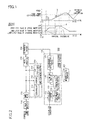
- Fig. 1 is a diagram for explaining a charge/discharge method according to the embodiment of the present invention.
- a graph on the upper side in Fig 1 shows an estimated amount of power consumption per unit time period in a certain facility
- a graph on the lower side in Fig. 1 shows a charge amount per unit time period of a rechargeable battery installed in the facility, which corresponds to the estimated power consumption.
- Fig. 2 is a diagram showing a configuration of a charge/discharge system 500 according to the embodiment of the present invention.
- the following description assumes a case where the charge/discharge system 500 according to this embodiment is installed in a facility such as a supermarket, a convenience store, or the like. There is, however, no limitation thereto.
- the charge/discharge system 500 includes a charge/discharge control apparatus 100, a rechargeable battery 200, a power receiver 210, a power meter 220, an AC/DC convertor 230, and power consuming equipment 300.
- a charge/discharge control apparatus 100 for example, a refrigerator 310, a showcase 320, and an air conditioner 330 are provided.
- the rechargeable battery 200 is a lithium-ion battery.
- the power receiver 210 introduces commercial power (AC power) into the facility.
- the power meter 220 measures actual power consumption of the power consuming equipment 300 in the facility and outputs a result of the measurement to the charge/discharge control apparatus 100 (to be more exact, an after-mentioned measurement portion 110).
- an average value of power consumption per unit time is defined as actual power consumption.
- the AC/DC convertor 230 converts alternating current power supplied from a commercial power source into direct current power and supplies the direct current power to the rechargeable battery 200.
- the AC/DC convertor 230 also converts direct current power supplied from the rechargeable battery 200 into alternating current power and supplies the alternating current power to the power consuming equipment 300 in the facility.
- the charge/discharge control apparatus 100 controls charging/discharging of the rechargeable battery 200.
- the charge/discharge control apparatus 100 includes the measurement portion 110, a learning data management portion 120, a learning data holding portion 130, an estimation portion 140, and a rechargeable battery control portion 150.
- each of these constituent components can be realized, in terms of hardware, by an arbitrary processor or memory or any other type of LSI and are realized, in terms of software, by, for example, a program loaded into a memory, depicted herein are functional blocks that are realized by such hardware and software used in a coordinated manner. It is therefore understandable to those skilled in the art that these functional blocks can be realized in various forms by hardware alone, software alone, or the combination of hardware and software.
- the measurement portion 110 acquires environmental data at a given cycle (for example, every 10 minutes).
- Environmental data includes an air temperature and a humidity outside the facility, a temperature and a humidity inside the facility, and so on.
- an air temperature outside the facility hereinafter, referred to as an outside air temperature
- the measurement portion 110 also acquires actual power consumption of the power consuming equipment 300 at a given cycle (for example, every 10 minutes) from the power meter 220.
- the learning data management portion 120 registers, as learning data, environmental data (in this embodiment, an outside air temperature) and actual power consumption acquired by the measurement portion 110 in the learning data holding portion 130.
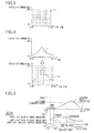
- Fig. 3 is a diagram showing one example of a data structure in the learning data holding portion 130.
- Fig. 3 depicts an example in which a two-dimensional table using a time zone and an outside air temperature as parameters is formulated, and, as learning data, measured values of actual power consumption are stored in cells "e" in the table. For example, a configuration is possible in which values of actual power consumption measured in the most recent 10 measurements are stored in the cells "e".
- environmental conditions used to obtain learning data in addition to a time zone, an air temperature, and a humidity, other parameters such as audience data, an estimated number of visitors, a bargain day, a day of the week, and so on can be used.
- the estimation portion 140 estimates power usage per unit time period. For example, the estimation portion 140 estimates power usage per unit time period of a certain day on a day before the certain day. More specifically, the estimation portion 140 acquires learning data on power usage (for example, actual power consumption) recorded using a time zone and at least one environmental condition (in this embodiment, an outside air temperature) as parameters and estimated values of the environmental condition (in this embodiment, an outside air temperature) of a unit time period, and based thereon, estimates power usage per unit time period.
- power usage for example, actual power consumption
- an environmental condition in this embodiment, an outside air temperature
- the estimation portion 140 acquires, from a meteorological database 400 formulated in an external server to which the estimation portion 140 is connected via a network (for example, the Internet), meteorological data (in this embodiment, an outside air temperature per unit time period) of a next day. Based on the outside air temperature per unit time period, the estimation portion 140 refers to the learning data holding portion 130 and estimates power usage per unit time period of the next day.
- a meteorological database 400 formulated in an external server to which the estimation portion 140 is connected via a network (for example, the Internet), meteorological data (in this embodiment, an outside air temperature per unit time period) of a next day.
- the estimation portion 140 Based on the outside air temperature per unit time period, the estimation portion 140 refers to the learning data holding portion 130 and estimates power usage per unit time period of the next day.
- Fig. 4 is a diagram for explaining a process of estimating power usage per unit time period of a next day based on an outside air temperature per unit time period of the next day.
- a graph on the upper side in Fig. 4 shows an outside air temperature "f" per unit time period of a next day acquired from the meteorological database 400.
- a graph on the lower side in Fig. 4 shows the table shown in Fig. 3 , in which values of actual power consumption are stored.
- the estimation portion 140 determines a value of estimated power consumption with respect to each time zone.
- Cells "g" in a gray scale indicate cells corresponding to values of the outside air temperature "f" per unit time period of the next day.
- maximum values average values may be used instead
- the rechargeable battery control portion 150 Based on a result of the estimation by the estimation portion 140, the rechargeable battery control portion 150 performs control such that an excess amount of power over a target power value within the above-described unit time period (in this embodiment, the day as an estimation object) is charged into the rechargeable battery 200 and is discharged from the rechargeable battery 200 during a time zone in which the target power value is exceeded.
- an upper limit value of a charge amount (in this embodiment, for example, 80%) with respect to full charge of the rechargeable battery 200 is preset. Deterioration of a rechargeable battery is accelerated to a degree varying with a charge amount, and particularly in a case where the rechargeable battery is almost fully charged or a charge amount thereof is almost nil, compared with a case where the charge amount thereof is about half, the above-described acceleration degree is increased.
- the above-described upper limit value and an after-mentioned lower limit value are set to include therebetween a range of values at which the deterioration acceleration degree is increased. This specification describes this as a characteristic of a rechargeable battery.
- the rechargeable battery control portion 150 charges the rechargeable battery 200 to the upper limit value during a time zone in which power usage per unit time period estimated by the estimation portion 140 is low compared with any other time period, and charges thereinto an excess over the upper limit value during a time zone closer to a time zone in which the target power value is exceeded than the time zone in which the rechargeable battery 200 is charged to the upper limit value.
- the above-described time zone in which power usage is low may be regarded as a time zone in which estimated power consumption does not exceed a predetermined set value, a time zone in which a cumulative sum of values of estimated power consumption is smallest, or a time zone including a time when estimated power consumption is lowest.
- a time zone corresponds to a midnight time zone.
- the electricity cost is set to be lower in a midnight time zone than in a normal time zone (as of June, 2010).
- the rechargeable battery control portion 150 charges the rechargeable battery 200 to the upper limit value during the time zone in which the electricity cost is set to be lower than in a normal time zone, and thus a further reduction in electric power cost can be expected.
- the time zone closer to the time zone in which the target power value is exceeded is a time zone in which charging of an excess over the upper limit value is scheduled to start such that it is ended at or immediately before a starting time of the time zone in which the target power value is exceeded.
- a length of time in which the rechargeable battery 200 is in a fully charged state can be maximally reduced.
- a lower limit value of the charge amount (in this embodiment, for example, 50%) with respect to full charge of the rechargeable battery 200 may be set.
- the rechargeable battery control portion 150 does not perform prior charging with respect to the rechargeable battery 200.
- the rechargeable battery control portion 150 performs charging such that a charge amount remaining after discharging of the excess amount of power attains the lower limit value.
- Fig. 5 is a diagram for explaining a charge/discharge method in a case where charging beyond an upper limit value of a charge amount is not performed.
- Fig. 6 is a diagram for explaining a charge/discharge method in a case where charging beyond full charge needs to be performed.
- Fig. 7 is a diagram showing a relationship between a charging duration and a charge amount of the rechargeable battery 200.
- the rechargeable battery control portion 150 performs control such that charging with respect to the rechargeable battery 200 is not performed. This aims to reduce the number of times charging/discharging is performed and thereby to prevent capacity deterioration of the rechargeable battery 200.
- the rechargeable battery control portion 150 performs charging of an amount of (lower limit value + x - z)% such that a charge amount remaining after discharging of the excess amount of power attains the lower limit value.
- a charge current for charging a rechargeable battery is determined based on a charging characteristic of the rechargeable battery.
- the rechargeable battery control portion 150 sets a charge current value to be decreased so that the target power value will not be exceeded.
- a charging duration is determined based on a charging characteristic (see Fig. 7 ) of a battery used. In a case where a charge current value is set to be decreased, a charging duration is set to be increased. For example, when a charge current value is set to be decreased by half, presumably, a charging duration becomes double. Based on the charging duration thus presumed, the rechargeable battery control portion 150 starts charging such that the charging is completed by an ending time of a time zone in which power usage is low (for example, a midnight time zone (herein, 23:00 to 7:00)).
- a graph on the upper side in Fig. 5 shows estimated power consumption per unit time period in a facility
- a graph on the lower side in Fig. 5 shows a charge amount per unit time period of the rechargeable battery 200 installed in the facility, which corresponds to the estimated power consumption.
- the estimation portion 140 estimates power consumption of a next day
- the rechargeable battery control portion 150 performs charging of an excess amount of power based on the estimated power consumption (see a region "i") during a time zone in which power usage is low (see a block "h").
- the charging is completed by a time earlier than 7:00 a.m., until which an electricity billing rate for a midnight time zone is applied.
- charging of an excess over the above-described upper limit value is not necessary, and there is no time period in which full charge is achieved.
- a charge amount after charging (lower limit value + x)% is larger than the above-described upper limit value
- the following process is performed. That is, an excess over the above-described upper limit value (lower limit value + x - upper limit value)% is charged immediately before a time zone in which discharging is performed (hereinafter, referred to as second charging).
- a charging duration of the second charging is also determined based on a charging characteristic of a rechargeable battery used (see Fig. 7 ). Based on the charging duration thus determined, the rechargeable battery control portion 150 starts the charging such that the charging is completed by a time immediately before the time zone in which discharging is performed.
- a graph on the upper side in Fig. 6 shows estimated power consumption per unit time period in a facility
- a graph on the lower side in Fig. 6 shows a charge amount per unit time period of the rechargeable battery 200 installed in the facility, which corresponds to the estimated power consumption.
- the estimation portion 140 estimates power consumption of a next day
- the rechargeable battery control portion 150 performs charging of an excess amount of power based on the estimated power consumption (see a region "l") during a time zone in which power usage is low (see a block "j") (hereinafter, referred to as first charging).
- the first charging is completed by a time earlier than 7:00 a.m., until which an electricity billing rate for a midnight time zone is applied.
- the first charging is performed to such an extent that the above-described upper limit value is not exceeded.
- the rechargeable battery control portion 150 performs, as the second charging, charging of an excess over the above-described upper limit value immediately before a time zone in which discharging is performed (see a block "k"). This can reduce a length of time at full charge (see a circled area "m").
- a lower limit value of a discharge amount (in this embodiment, for example, 20%) with respect to full charge of the rechargeable battery 200 may be set.
- the rechargeable battery control portion 150 performs discharging to such an extent that the discharge amount does not fall below the lower limit value thereof.
- z% is discharged from the rechargeable battery 200 to such an extent that the discharge amount does not fall below a first lower limit value thereof (see “h” in Fig. 6 ). This can suppress capacity deterioration due to over-discharging.
- a second lower limit value of a discharge amount in this embodiment, for example, 10%
- a number of times of discharging to a second lower limit value a number of times a discharge amount falls below a first lower limit value and discharging to a second lower limit value is performed
- the above-described number of times of discharging to a second lower limit value can be changed depending on a characteristic of a rechargeable battery and may be an absolute number of times or a number of times per unit time period (for example, 10 times per year or the like).
- the rechargeable battery control portion 150 may permit discharging to the second lower limit value. That is, discharging to the second lower limit value below the first lower limit value of the discharge amount may be performed.
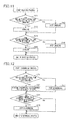
- Fig. 8 is a flow chart showing an entire operation of the charge/discharge system 500 according to the embodiment of the present invention. Details of respective processes performed in the operation will be described with reference to Figs. 9 to 12 .
- the measurement portion 110 executes a power value acquiring process
- the learning data management portion 120 executes a learning process (S10).
- the estimation portion 140 executes an estimation process (S20).
- the rechargeable battery control portion 150 executes a charging process (S40).
- the rechargeable battery control portion 150 executes a discharging process (S50). These processes are executed repeatedly.
- Fig. 9 is a flow chart showing the details of the power value acquiring process and the learning process.
- the measurement portion 110 judges whether or not periodic timing for sensor acquisition has come (S11), and if it has come (Yes at S11), acquires an outside air temperature and actual power consumption (S12).
- the learning data management portion 120 stores values of the actual power consumption in learning data cells segmented in terms of environmental conditions (in this embodiment, in terms of a time zone and an outside air temperature) (S 13).
- Fig. 10 is a flow chart showing the details of the estimation process.
- the estimation portion 140 judges whether or not an estimation time designated by a user (for example, 23:00 on a day before) has come (S21), and if it has come (Yes at S21), acquires meteorological data (in this embodiment, an outside air temperature per unit time period) of a next day (S22). Based on the meteorological data, maximum values stored in the learning data cells segmented in terms of a time zone and an outside air temperature are extracted as values of estimated power (S23), and an estimated power consumption pattern is determined (S24).
- an estimation time designated by a user for example, 23:00 on a day before
- meteorological data in this embodiment, an outside air temperature per unit time period
- the estimation portion 140 determines an excess amount of power (S25), and based thereon, determines a discharge starting time, a discharge ending time, and a discharge pattern (S26).
- a discharge pattern refers to an excess amount of power per unit time, which is obtained by subtracting a target power value from the estimated power consumption pattern.
- the estimation portion 140 compares a value obtained by subtracting an excess amount of power from a present charge amount with a lower limit value of a charge amount (S27). If the former is less than the latter (Yes at S27), the estimation portion 140 determines a first charge amount of charging to be performed during a time zone in which power usage is low (S28) and determines a starting time and an ending time of the charging (S29). If the former is not less than the latter (No at S27), charging is not performed (S30). More specifically, an invalid value is set for each of the first charging starting time and a second charging starting time.
- the estimation portion 140 compares a value obtained by adding an excess amount of power to a present charge amount with an upper limit value of a charge amount (S31). If the former exceeds the latter (Yes at S31), the estimation portion 140 determines a second charge amount of charging to be performed during a time zone immediately before discharging (S32) and determines the starting time and an ending time of the charging (S33). If the former is not more than the latter (No at S31), the processes at Steps S32 and 33 are skipped. Though not shown in Fig. 10 , during a time zone in which a target power value is presumed to be exceeded as a result of charging, a charge current value is set to be decreased, and a charging duration in that case is determined.
- Fig. 11 is a flow chart showing the details of the charging process.
- the rechargeable battery control portion 150 performs the first charging with respect to the rechargeable battery 200 (S42).
- the first charging is stopped (S43). In a case where an invalid value is set for the first charging starting time, the charging is not performed.
- the rechargeable battery control portion 150 performs the second charging with respect to the rechargeable battery 200 (S45). In a time period other than this time period (No at S44), the second charging is stopped (S46). In a case where an invalid value is set for the second charging starting time, the charging is not performed.
- Fig. 12 is a flow chart showing the details of the discharging process.
- the rechargeable battery control portion 150 performs the discharging in accordance with the discharge pattern (S52).
- the discharging is stopped (S53).
- the rechargeable battery control portion 150 stops the discharging (S55). If the charge amount exceeds the lower limit value of the discharge amount (No at S54), the discharging is performed in accordance with the discharge pattern.
- a length of time at full charge is reduced, and thus the life span of the rechargeable battery can be increased. Furthermore, the number of times charging/discharging is performed is reduced, which also allows the life span of the rechargeable battery to be increased. Moreover, over-discharging is suppressed, which also allows the life span of the rechargeable battery to be increased. In addition, charging is performed during a midnight time zone, and thus a reduction in electricity cost can be achieved.
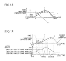
- Fig. 13 is a diagram for explaining a charge/discharge method according to Modification Example 1.
- a transition curve "s" indicates a power consumption pattern estimated on a day before at, for example, 23:00.
- a transition curve "r” indicates a power consumption pattern estimated in the morning on a present day at a time "p" (for example, 7:00) based on up-to-date meteorological information acquired from the meteorological database 400.
- the estimation portion 140 determines an excess amount of power (see a region "v"), and based thereon, charging is performed during a time zone in which power usage is low (see a block "o"). Based on the power consumption pattern indicated by the transition curve "r", which is obtained by performing re-estimation in the morning on the present day, the estimation portion 140 re-determines an excess amount of power. If a result of the re-determination finds that a present charge amount is not sufficient enough to fully obtain the re-determined excess amount of power, an amount of power over an obtainable amount is charged immediately before discharging (see a block "p").
- the estimation portion 140 may be configured such that, every time meteorological information in the meteorological database 400 is updated, it performs the above-described re-determination of an excess amount of power and changes a charge amount accordingly. As discussed above, according to Modification Example 1, accuracy in estimating a power consumption pattern can be increased, and thus further optimization of charge/discharge control can be achieved.
- Fig. 14 is a diagram for explaining a charge/discharge method according to Modification Example 2.
- a time zone in which power usage is low a midnight time zone in which the electricity cost is low is adopted as an example.
- the electricity cost varies between in a daytime power time zone and in a midnight power time zone, with midnight power set to be cheaper compared with daytime power. There may be a case, however, where the electricity cost does not vary depending on a time zone.
- a general way is to perform constant-current charging to about 80% of a charge amount at a high speed and to subsequently perform constant-voltage charging at a low speed.
- the constant-current charging to not more than about 80% of a charge amount is performed during a time zone in which power usage is low.
- the rechargeable battery control portion 150 could be configured as follows. That is, based on power usage per unit time period estimated by the estimation portion 140, the rechargeable battery control portion 150 schedules charging to the above-described upper limit value such that it is completed by a time when the power usage being falling or leveling off turns to rise.
- a graph on the upper side in Fig. 14 shows estimated power consumption per unit time period in a facility
- a graph on the lower side in Fig. 14 shows a charge amount per unit time period of the rechargeable battery 200 installed in the facility, which corresponds to the estimated power consumption.
- the estimation portion 140 estimates power consumption of a next day, and the rechargeable battery control portion 150 schedules the first charging such that it is completed by a time immediately before a gradient of variations in the estimated power consumption rises (see a block "t").
- the rechargeable battery control portion 150 performs, as the second charging, charging of an excess over the above-described upper limit value immediately before a time zone in which discharging is performed (see a block "u").
- the charge/discharge system 500 is applied to a facility such as a store or the like.
- the charge/discharge system 500 can be applied also to an individual household.
- charge/discharge control apparatus 110 measurement portion, 120 leaning data management portion, 130 leaning data holding portion, 140 estimation portion, 150 rechargeable battery control portion, 200 rechargeable battery, 210 power receiver, 220 power meter, 230 AC/DC convertor, 300 power consuming equipment, 310 refrigerator, 320 showcase, 330 air conditioner, 400 meteorological database, 500 charge/discharge system
Landscapes
- Engineering & Computer Science (AREA)
- Power Engineering (AREA)
- Manufacturing & Machinery (AREA)
- Chemical & Material Sciences (AREA)
- Chemical Kinetics & Catalysis (AREA)
- Electrochemistry (AREA)
- General Chemical & Material Sciences (AREA)
- Charge And Discharge Circuits For Batteries Or The Like (AREA)
- Secondary Cells (AREA)
- Supply And Distribution Of Alternating Current (AREA)
Abstract
Description
- The present invention relates to a charge/discharge control apparatus that controls charging/discharging of a rechargeable battery.
- Recent years have seen an increasing number of cases where an electric power user introduces a charging system capable of power peak shaving. In this type of charging system, a rechargeable battery is charged during a time zone in which power usage is low, and electricity thus charged is discharged from the rechargeable battery during a time zone in which the power usage reaches its peak so that peak power of the power usage is reduced. Furthermore, there have also been an increasing number of cases of introducing a charging system in which a rechargeable battery is charged with less costly midnight electricity, and the electricity is discharged in the daytime so that a daytime electricity cost is reduced. The introduction of these types of charging systems allows a total electricity cost to be reduced.
- As a rechargeable battery that is incorporated into such a charging system, typically, a secondary battery such as a lithium-ion battery, a nickel metal hydride battery, a lead battery, or the like is used. A lithium-ion battery, in particular, is lightweight and high in capacity and in output and thus has been receiving attention as a rechargeable battery for the above-described types of charging systems.
- Patent Document 1:
JP-A-2009-194947 - The life span of a lithium-ion battery can vary largely depending on how the lithium-ion battery is used. Recovering an initial cost of introducing a battery by reducing the electric power cost requires that the battery have as long a life span as possible. One factor causing a decrease in battery life span is that charging/discharging is performed an increased number of times, and other such factors include keeping a battery in a fully charged state at a high temperature, overcharging a battery, and over-discharging a battery.
- Now, a case is assumed where, in a charging system in which a lithium-ion battery is charged during a time zone in which power usage is low and is discharged during a time zone in which the power usage reaches its peak, the lithium-ion battery is charged to an almost fully charged state during, as the time zone in which power usage is low, a midnight time zone in which the electricity region is at a low cost and is discharged during a time zone on a next day when the power usage reaches its peak (for example, around noon). In this case, the lithium-ion battery is kept in an almost fully charged state for a long time. That is, one of the factors causing a decrease in battery life span arises in this case. Furthermore, in a situation where an ambient temperature around the battery is high such as in summer, a greater degree of capacity deterioration occurs in the battery, leading to a further decrease in the life span of the battery. Herein, capacity deterioration refers to a state where an initial full charge capacity can no longer be achieved even by charging to a fully charged state. In general, when the capacity of a battery is decreased to about 60% of its initial full charge capacity, it is judged that the battery has reached the end of its life span.
- The present invention has been made in view of the above, and it is an object of the present invention to provide a technique for, in a system in which a rechargeable battery is charged when power usage is low and is discharged when the power usage is high, increasing the life span of the rechargeable battery.
- A charge/discharge control apparatus according to a certain aspect of the present invention is a charge/discharge control apparatus that controls charging/discharging of a rechargeable battery and includes: an estimation portion that estimates power usage per unit time period; and a rechargeable battery control portion that performs control such that, based on a result of the estimation by the estimation portion, an excess amount of power over a target power value within the unit time period is charged into the rechargeable battery and is discharged from the rechargeable battery during a time zone in which the target power value is exceeded. In the rechargeable battery control portion, an upper limit value of a charge amount with respect to full charge of the rechargeable battery is set. In a case where the rechargeable battery needs to be charged beyond the upper limit value, the rechargeable battery control portion charges the rechargeable battery to the upper limit value during a time zone in which the power usage estimated by the estimation portion is low, and charges thereinto an excess over the upper limit value during a time zone close to the time zone in which the target power value is exceeded. Herein, a charge amount refers to a present amount of electricity stored, and this term encompasses, in addition to a ratio thereof to full charge (a state of charge SOC: "%"), an absolute amount "Ah" of a charge amount. A state of charge SOC is defined as a present charge amount (the absolute amount "Ah") of a rechargeable battery / a charge amount (the absolute amount "Ah") at full charge.
- According to the present invention, in a system in which a rechargeable battery is charged when power usage is low and is discharged when the power usage is high, the life span of the rechargeable battery can be increased.
-
- [
Fig. 1 ] A diagram for explaining a charge/discharge method according to an embodiment of the present invention. - [
Fig. 2 ] A diagram showing a configuration of a charge/discharge system according to the embodiment of the present invention. - [
Fig. 3 ] A diagram showing one example of a data structure in a leaning data holding portion. - [
Fig. 4 ] A diagram for explaining a process of estimating power usage per unit time period of a next day based on an outside air temperature per unit time period of the next day. - [
Fig. 5 ] A diagram for explaining a charge/discharge method in a case where charging beyond an upper limit value of a charge amount is not performed. - [
Fig. 6 ] A diagram for explaining a charge/discharge method in a case where charging beyond full charge needs to be performed. - [
Fig. 7 ] A diagram showing a relationship between a charging duration and a charge amount of a rechargeable battery. - [
Fig. 8 ] A flow chart showing an entire operation of the charge/discharge system according to the embodiment of the present invention. - [
Fig. 9 ] A flow chart showing details of a power value acquiring process and a learning process. - [
Fig. 10 ] A flow chart showing details of an estimation process. - [
Fig. 11 ] A flow chart showing details of a charging process. - [
Fig. 12 ] A flow chart showing details of a discharging process. - [
Fig. 13 ] A diagram for explaining a charge/discharge method according to Modification Example 1. - [
Fig. 14 ] A diagram for explaining a charge/discharge method according to Modification Example 2. - First, prior to a detailed description of an embodiment of the present invention, the following describes an outline of the embodiment of the present invention.
Fig. 1 is a diagram for explaining a charge/discharge method according to the embodiment of the present invention. A graph on the upper side inFig 1 shows an estimated amount of power consumption per unit time period in a certain facility, and a graph on the lower side inFig. 1 shows a charge amount per unit time period of a rechargeable battery installed in the facility, which corresponds to the estimated power consumption. As shown inFig. 1 , power consumption of a next day is estimated, and an amount of power (hereinafter, where appropriate, referred to as an excess amount of power (see a region "c")) by which the estimated power consumption exceeds a target power value (herein, electric power supplied under contract with a power company) is charged during a time zone in which power usage is low (see a block "a"). In this case, however, an excess over an upper limit value of a charge amount (for example, 80% of full charge) is charged immediately before a time zone in which discharging is performed (see a block "b"). This extremely reduces a length of time in which the rechargeable battery is at full charge (see a circled area "d") and thus can prevent deterioration of the battery. -
Fig. 2 is a diagram showing a configuration of a charge/discharge system 500 according to the embodiment of the present invention. The following description assumes a case where the charge/discharge system 500 according to this embodiment is installed in a facility such as a supermarket, a convenience store, or the like. There is, however, no limitation thereto. - The charge/
discharge system 500 includes a charge/discharge control apparatus 100, arechargeable battery 200, apower receiver 210, apower meter 220, an AC/DC convertor 230, andpower consuming equipment 300. In the facility, as thepower consuming equipment 300, for example, arefrigerator 310, ashowcase 320, and anair conditioner 330 are provided. This embodiment assumes that therechargeable battery 200 is a lithium-ion battery. - The
power receiver 210 introduces commercial power (AC power) into the facility. Thepower meter 220 measures actual power consumption of thepower consuming equipment 300 in the facility and outputs a result of the measurement to the charge/discharge control apparatus 100 (to be more exact, an after-mentioned measurement portion 110). Herein, for example, an average value of power consumption per unit time (for example, 10 minutes) is defined as actual power consumption. The AC/DC convertor 230 converts alternating current power supplied from a commercial power source into direct current power and supplies the direct current power to therechargeable battery 200. The AC/DC convertor 230 also converts direct current power supplied from therechargeable battery 200 into alternating current power and supplies the alternating current power to thepower consuming equipment 300 in the facility. - The charge/
discharge control apparatus 100 controls charging/discharging of therechargeable battery 200. The charge/discharge control apparatus 100 includes themeasurement portion 110, a learningdata management portion 120, a learningdata holding portion 130, anestimation portion 140, and a rechargeablebattery control portion 150. Although each of these constituent components can be realized, in terms of hardware, by an arbitrary processor or memory or any other type of LSI and are realized, in terms of software, by, for example, a program loaded into a memory, depicted herein are functional blocks that are realized by such hardware and software used in a coordinated manner. It is therefore understandable to those skilled in the art that these functional blocks can be realized in various forms by hardware alone, software alone, or the combination of hardware and software. - The
measurement portion 110 acquires environmental data at a given cycle (for example, every 10 minutes). Environmental data includes an air temperature and a humidity outside the facility, a temperature and a humidity inside the facility, and so on. For the sake of simplifying an explanation, this embodiment describes below a case where an air temperature outside the facility (hereinafter, referred to as an outside air temperature), which is highly correlated with power consumption, is acquired. Themeasurement portion 110 also acquires actual power consumption of thepower consuming equipment 300 at a given cycle (for example, every 10 minutes) from thepower meter 220. - The learning
data management portion 120 registers, as learning data, environmental data (in this embodiment, an outside air temperature) and actual power consumption acquired by themeasurement portion 110 in the learningdata holding portion 130.
Fig. 3 is a diagram showing one example of a data structure in the learningdata holding portion 130.Fig. 3 depicts an example in which a two-dimensional table using a time zone and an outside air temperature as parameters is formulated, and, as learning data, measured values of actual power consumption are stored in cells "e" in the table. For example, a configuration is possible in which values of actual power consumption measured in the most recent 10 measurements are stored in the cells "e". As environmental conditions used to obtain learning data, in addition to a time zone, an air temperature, and a humidity, other parameters such as audience data, an estimated number of visitors, a bargain day, a day of the week, and so on can be used. - The
estimation portion 140 estimates power usage per unit time period. For example, theestimation portion 140 estimates power usage per unit time period of a certain day on a day before the certain day. More specifically, theestimation portion 140 acquires learning data on power usage (for example, actual power consumption) recorded using a time zone and at least one environmental condition (in this embodiment, an outside air temperature) as parameters and estimated values of the environmental condition (in this embodiment, an outside air temperature) of a unit time period, and based thereon, estimates power usage per unit time period. - When a predetermined estimation time has come, the
estimation portion 140 acquires, from ameteorological database 400 formulated in an external server to which theestimation portion 140 is connected via a network (for example, the Internet), meteorological data (in this embodiment, an outside air temperature per unit time period) of a next day. Based on the outside air temperature per unit time period, theestimation portion 140 refers to the learningdata holding portion 130 and estimates power usage per unit time period of the next day. -
Fig. 4 is a diagram for explaining a process of estimating power usage per unit time period of a next day based on an outside air temperature per unit time period of the next day. A graph on the upper side inFig. 4 shows an outside air temperature "f" per unit time period of a next day acquired from themeteorological database 400. A graph on the lower side inFig. 4 shows the table shown inFig. 3 , in which values of actual power consumption are stored. Based on the data of actual power consumption obtained in the most recent 10 measurements, which are stored in the cells in the table, theestimation portion 140 determines a value of estimated power consumption with respect to each time zone. Cells "g" in a gray scale indicate cells corresponding to values of the outside air temperature "f" per unit time period of the next day. As a method for determining estimated power consumption, for example, maximum values (average values may be used instead) of actual power consumption obtained in the most recent 10 measurements are selected and used. - Based on a result of the estimation by the
estimation portion 140, the rechargeablebattery control portion 150 performs control such that an excess amount of power over a target power value within the above-described unit time period (in this embodiment, the day as an estimation object) is charged into therechargeable battery 200 and is discharged from therechargeable battery 200 during a time zone in which the target power value is exceeded. - In the rechargeable
battery control portion 150, depending on a characteristic of therechargeable battery 200, an upper limit value of a charge amount (in this embodiment, for example, 80%) with respect to full charge of therechargeable battery 200 is preset. Deterioration of a rechargeable battery is accelerated to a degree varying with a charge amount, and particularly in a case where the rechargeable battery is almost fully charged or a charge amount thereof is almost nil, compared with a case where the charge amount thereof is about half, the above-described acceleration degree is increased. The above-described upper limit value and an after-mentioned lower limit value are set to include therebetween a range of values at which the deterioration acceleration degree is increased. This specification describes this as a characteristic of a rechargeable battery. In a case where therechargeable battery 200 needs to be charged beyond the upper limit value, the rechargeablebattery control portion 150 charges therechargeable battery 200 to the upper limit value during a time zone in which power usage per unit time period estimated by theestimation portion 140 is low compared with any other time period, and charges thereinto an excess over the upper limit value during a time zone closer to a time zone in which the target power value is exceeded than the time zone in which therechargeable battery 200 is charged to the upper limit value. - The above-described time zone in which power usage is low may be regarded as a time zone in which estimated power consumption does not exceed a predetermined set value, a time zone in which a cumulative sum of values of estimated power consumption is smallest, or a time zone including a time when estimated power consumption is lowest. Typically, such a time zone corresponds to a midnight time zone. In Japan, the electricity cost is set to be lower in a midnight time zone than in a normal time zone (as of June, 2010). Hence, normally, the rechargeable
battery control portion 150 charges therechargeable battery 200 to the upper limit value during the time zone in which the electricity cost is set to be lower than in a normal time zone, and thus a further reduction in electric power cost can be expected. - Preferably, the time zone closer to the time zone in which the target power value is exceeded is a time zone in which charging of an excess over the upper limit value is scheduled to start such that it is ended at or immediately before a starting time of the time zone in which the target power value is exceeded. In this case, a length of time in which the
rechargeable battery 200 is in a fully charged state can be maximally reduced. - In the rechargeable
battery control portion 150, depending on the characteristic of therechargeable battery 200, a lower limit value of the charge amount (in this embodiment, for example, 50%) with respect to full charge of therechargeable battery 200 may be set. In this case, when a ratio of a charge amount obtained by subtracting an excess amount of power estimated by theestimation portion 140 from a present charge amount of therechargeable battery 200 to full charge of therechargeable battery 200 is not less than the lower limit value, the rechargeablebattery control portion 150 does not perform prior charging with respect to therechargeable battery 200. Conversely, when the above-described ratio of a charge amount to full charge of therechargeable battery 200 is smaller than the lower limit value, the rechargeablebattery control portion 150 performs charging such that a charge amount remaining after discharging of the excess amount of power attains the lower limit value. - The following describes a specific example for explaining this. It is premised that, where an excess amount of power is indicated as X [kWh], a full charge amount of the
rechargeable battery 200 as Y [kWh], and a present charge amount as Z [kWh], a percentage of an excess amount of power to a full charge amount is expressed as ((X/Y) X 100)%, and a percentage of a present charge amount to a full charge amount is expressed as ((Z/Y) X 100)%. In the following, the former and latter percentages are indicated as x% and z%, respectively. -
Fig. 5 is a diagram for explaining a charge/discharge method in a case where charging beyond an upper limit value of a charge amount is not performed.Fig. 6 is a diagram for explaining a charge/discharge method in a case where charging beyond full charge needs to be performed.Fig. 7 is a diagram showing a relationship between a charging duration and a charge amount of therechargeable battery 200. - In a case where a difference obtained by subtracting an excess amount of power from a present charge amount is not less than the above-described lower limit value (in this embodiment, for example, 30%) (z - x ≥ lower limit value), the rechargeable
battery control portion 150 performs control such that charging with respect to therechargeable battery 200 is not performed. This aims to reduce the number of times charging/discharging is performed and thereby to prevent capacity deterioration of therechargeable battery 200. In a case where the above-described difference is smaller than the lower limit value (z - x < lower limit value), during a time zone in which estimated power usage is low, the rechargeablebattery control portion 150 performs charging of an amount of (lower limit value + x - z)% such that a charge amount remaining after discharging of the excess amount of power attains the lower limit value. - A charge current for charging a rechargeable battery is determined based on a charging characteristic of the rechargeable battery. During a time zone in which a target power value is presumed to be exceeded as a result of charging, however, the rechargeable
battery control portion 150 sets a charge current value to be decreased so that the target power value will not be exceeded. A charging duration is determined based on a charging characteristic (seeFig. 7 ) of a battery used. In a case where a charge current value is set to be decreased, a charging duration is set to be increased. For example, when a charge current value is set to be decreased by half, presumably, a charging duration becomes double. Based on the charging duration thus presumed, the rechargeablebattery control portion 150 starts charging such that the charging is completed by an ending time of a time zone in which power usage is low (for example, a midnight time zone (herein, 23:00 to 7:00)). - A graph on the upper side in
Fig. 5 shows estimated power consumption per unit time period in a facility, and a graph on the lower side inFig. 5 shows a charge amount per unit time period of therechargeable battery 200 installed in the facility, which corresponds to the estimated power consumption. Theestimation portion 140 estimates power consumption of a next day, and the rechargeablebattery control portion 150 performs charging of an excess amount of power based on the estimated power consumption (see a region "i") during a time zone in which power usage is low (see a block "h"). Herein, the charging is completed by a time earlier than 7:00 a.m., until which an electricity billing rate for a midnight time zone is applied. InFig. 5 , charging of an excess over the above-described upper limit value is not necessary, and there is no time period in which full charge is achieved. - On the other hand, in a case where a charge amount after charging (lower limit value + x)% is larger than the above-described upper limit value, the following process is performed. That is, an excess over the above-described upper limit value (lower limit value + x - upper limit value)% is charged immediately before a time zone in which discharging is performed (hereinafter, referred to as second charging). A charging duration of the second charging is also determined based on a charging characteristic of a rechargeable battery used (see
Fig. 7 ). Based on the charging duration thus determined, the rechargeablebattery control portion 150 starts the charging such that the charging is completed by a time immediately before the time zone in which discharging is performed. - A graph on the upper side in
Fig. 6 shows estimated power consumption per unit time period in a facility, and a graph on the lower side inFig. 6 shows a charge amount per unit time period of therechargeable battery 200 installed in the facility, which corresponds to the estimated power consumption. Theestimation portion 140 estimates power consumption of a next day, and the rechargeablebattery control portion 150 performs charging of an excess amount of power based on the estimated power consumption (see a region "l") during a time zone in which power usage is low (see a block "j") (hereinafter, referred to as first charging). Herein, the first charging is completed by a time earlier than 7:00 a.m., until which an electricity billing rate for a midnight time zone is applied. The first charging is performed to such an extent that the above-described upper limit value is not exceeded. The rechargeablebattery control portion 150 performs, as the second charging, charging of an excess over the above-described upper limit value immediately before a time zone in which discharging is performed (see a block "k"). This can reduce a length of time at full charge (see a circled area "m"). - In the rechargeable
battery control portion 150, depending on the characteristic of therechargeable battery 200, a lower limit value of a discharge amount (in this embodiment, for example, 20%) with respect to full charge of therechargeable battery 200 may be set. In this case, the rechargeablebattery control portion 150 performs discharging to such an extent that the discharge amount does not fall below the lower limit value thereof. To explain this using the above-described specific example, during a time zone in which estimated power consumption exceeds a target power value, z% is discharged from therechargeable battery 200 to such an extent that the discharge amount does not fall below a first lower limit value thereof (see "h" inFig. 6 ). This can suppress capacity deterioration due to over-discharging. Moreover, in the rechargeablebattery control portion 150, a second lower limit value of a discharge amount (in this embodiment, for example, 10%) and a number of times of discharging to a second lower limit value (a number of times a discharge amount falls below a first lower limit value and discharging to a second lower limit value is performed) may be set. The above-described number of times of discharging to a second lower limit value can be changed depending on a characteristic of a rechargeable battery and may be an absolute number of times or a number of times per unit time period (for example, 10 times per year or the like). In that case, if the above-described number of times of discharging to a second lower limit value is not more than a predetermined number of times, the rechargeablebattery control portion 150 may permit discharging to the second lower limit value. That is, discharging to the second lower limit value below the first lower limit value of the discharge amount may be performed. -
Fig. 8 is a flow chart showing an entire operation of the charge/discharge system 500 according to the embodiment of the present invention. Details of respective processes performed in the operation will be described with reference toFigs. 9 to 12 . Themeasurement portion 110 executes a power value acquiring process, and the learningdata management portion 120 executes a learning process (S10). Theestimation portion 140 executes an estimation process (S20). The rechargeablebattery control portion 150 executes a charging process (S40). The rechargeablebattery control portion 150 executes a discharging process (S50). These processes are executed repeatedly. -
Fig. 9 is a flow chart showing the details of the power value acquiring process and the learning process. Themeasurement portion 110 judges whether or not periodic timing for sensor acquisition has come (S11), and if it has come (Yes at S11), acquires an outside air temperature and actual power consumption (S12). The learningdata management portion 120 stores values of the actual power consumption in learning data cells segmented in terms of environmental conditions (in this embodiment, in terms of a time zone and an outside air temperature) (S 13). -
Fig. 10 is a flow chart showing the details of the estimation process. Theestimation portion 140 judges whether or not an estimation time designated by a user (for example, 23:00 on a day before) has come (S21), and if it has come (Yes at S21), acquires meteorological data (in this embodiment, an outside air temperature per unit time period) of a next day (S22). Based on the meteorological data, maximum values stored in the learning data cells segmented in terms of a time zone and an outside air temperature are extracted as values of estimated power (S23), and an estimated power consumption pattern is determined (S24). - Based on the estimated power consumption pattern, the
estimation portion 140 determines an excess amount of power (S25), and based thereon, determines a discharge starting time, a discharge ending time, and a discharge pattern (S26). A discharge pattern refers to an excess amount of power per unit time, which is obtained by subtracting a target power value from the estimated power consumption pattern. - The
estimation portion 140 compares a value obtained by subtracting an excess amount of power from a present charge amount with a lower limit value of a charge amount (S27). If the former is less than the latter (Yes at S27), theestimation portion 140 determines a first charge amount of charging to be performed during a time zone in which power usage is low (S28) and determines a starting time and an ending time of the charging (S29). If the former is not less than the latter (No at S27), charging is not performed (S30). More specifically, an invalid value is set for each of the first charging starting time and a second charging starting time. - In a case where the first charging is executed, the
estimation portion 140 compares a value obtained by adding an excess amount of power to a present charge amount with an upper limit value of a charge amount (S31). If the former exceeds the latter (Yes at S31), theestimation portion 140 determines a second charge amount of charging to be performed during a time zone immediately before discharging (S32) and determines the starting time and an ending time of the charging (S33). If the former is not more than the latter (No at S31), the processes at Steps S32 and 33 are skipped. Though not shown inFig. 10 , during a time zone in which a target power value is presumed to be exceeded as a result of charging, a charge current value is set to be decreased, and a charging duration in that case is determined. -
Fig. 11 is a flow chart showing the details of the charging process. During a time period from the starting time to the ending time of the first charging (Yes at S41), the rechargeablebattery control portion 150 performs the first charging with respect to the rechargeable battery 200 (S42). In a time period other than this time period (No at S41), the first charging is stopped (S43). In a case where an invalid value is set for the first charging starting time, the charging is not performed. - During a time period from the starting time to the ending time of the second charging (Yes at S44), the rechargeable
battery control portion 150 performs the second charging with respect to the rechargeable battery 200 (S45). In a time period other than this time period (No at S44), the second charging is stopped (S46). In a case where an invalid value is set for the second charging starting time, the charging is not performed. -
Fig. 12 is a flow chart showing the details of the discharging process. During a time period from the starting time to the ending time of discharging (Yes at S51), the rechargeablebattery control portion 150 performs the discharging in accordance with the discharge pattern (S52). In a time period other than this time period (No at S51), the discharging is stopped (S53). - If a charge amount of the
rechargeable battery 200 is not more than a lower limit value of a discharge amount (Yes at S54), the rechargeablebattery control portion 150 stops the discharging (S55). If the charge amount exceeds the lower limit value of the discharge amount (No at S54), the discharging is performed in accordance with the discharge pattern. - As discussed above, according to this embodiment, in a system in which a rechargeable battery is charged when power usage is low and is discharged when the power usage is high, a length of time at full charge is reduced, and thus the life span of the rechargeable battery can be increased. Furthermore, the number of times charging/discharging is performed is reduced, which also allows the life span of the rechargeable battery to be increased. Moreover, over-discharging is suppressed, which also allows the life span of the rechargeable battery to be increased. In addition, charging is performed during a midnight time zone, and thus a reduction in electricity cost can be achieved.
- The foregoing has discussed the present invention based on the embodiment. It is understandable to those skilled in the art that the embodiment is only illustrative and may be variously modified in terms of combinations of constituent components and processes, and that such modifications also fall within the scope of the present invention.
-
Fig. 13 is a diagram for explaining a charge/discharge method according to Modification Example 1. InFig. 13 , a transition curve "s" indicates a power consumption pattern estimated on a day before at, for example, 23:00. A transition curve "r" indicates a power consumption pattern estimated in the morning on a present day at a time "p" (for example, 7:00) based on up-to-date meteorological information acquired from themeteorological database 400. - Based on the power consumption pattern indicated by the transition curve "s", the
estimation portion 140 determines an excess amount of power (see a region "v"), and based thereon, charging is performed during a time zone in which power usage is low (see a block "o"). Based on the power consumption pattern indicated by the transition curve "r", which is obtained by performing re-estimation in the morning on the present day, theestimation portion 140 re-determines an excess amount of power. If a result of the re-determination finds that a present charge amount is not sufficient enough to fully obtain the re-determined excess amount of power, an amount of power over an obtainable amount is charged immediately before discharging (see a block "p"). - The
estimation portion 140 may be configured such that, every time meteorological information in themeteorological database 400 is updated, it performs the above-described re-determination of an excess amount of power and changes a charge amount accordingly. As discussed above, according to Modification Example 1, accuracy in estimating a power consumption pattern can be increased, and thus further optimization of charge/discharge control can be achieved. -
Fig. 14 is a diagram for explaining a charge/discharge method according to Modification Example 2. In the foregoing embodiment, as a time zone in which power usage is low, a midnight time zone in which the electricity cost is low is adopted as an example. In Japan, the electricity cost varies between in a daytime power time zone and in a midnight power time zone, with midnight power set to be cheaper compared with daytime power. There may be a case, however, where the electricity cost does not vary depending on a time zone. - As shown in
Fig. 7 referred to above, when charging a lithium-ion battery, a general way is to perform constant-current charging to about 80% of a charge amount at a high speed and to subsequently perform constant-voltage charging at a low speed. Thus, preferably, the constant-current charging to not more than about 80% of a charge amount is performed during a time zone in which power usage is low. - In view of the above-described findings without regard to the electricity cost, the rechargeable
battery control portion 150 could be configured as follows. That is, based on power usage per unit time period estimated by theestimation portion 140, the rechargeablebattery control portion 150 schedules charging to the above-described upper limit value such that it is completed by a time when the power usage being falling or leveling off turns to rise. - A graph on the upper side in
Fig. 14 shows estimated power consumption per unit time period in a facility, and a graph on the lower side inFig. 14 shows a charge amount per unit time period of therechargeable battery 200 installed in the facility, which corresponds to the estimated power consumption. Theestimation portion 140 estimates power consumption of a next day, and the rechargeablebattery control portion 150 schedules the first charging such that it is completed by a time immediately before a gradient of variations in the estimated power consumption rises (see a block "t"). The rechargeablebattery control portion 150 performs, as the second charging, charging of an excess over the above-described upper limit value immediately before a time zone in which discharging is performed (see a block "u"). - As discussed above, according to Modification Example 2, constant-current charging is performed during a time zone in which power usage is low, so that charging can be performed such that a target power value is not exceeded, and a charging duration can be reduced.
- In the foregoing discussion, as an example, the charge/
discharge system 500 is applied to a facility such as a store or the like. The charge/discharge system 500, however, can be applied also to an individual household. - 100 charge/discharge control apparatus, 110 measurement portion, 120 leaning data management portion, 130 leaning data holding portion, 140 estimation portion, 150 rechargeable battery control portion, 200 rechargeable battery, 210 power receiver, 220 power meter, 230 AC/DC convertor, 300 power consuming equipment, 310 refrigerator, 320 showcase, 330 air conditioner, 400 meteorological database, 500 charge/discharge system
Claims (8)
- A charge/discharge control apparatus that controls charging/discharging of a rechargeable battery, comprising:an estimation portion that estimates power usage per unit time period; anda rechargeable battery control portion that performs control such that, based on a result of the estimation by the estimation portion, power in an amount sufficient to allow discharging of an excess amount of power over a target power value within the unit time period is charged into the rechargeable battery, and an amount of power corresponding to the excess amount of power is discharged from the rechargeable battery during a time zone in which the target power value is exceeded,whereinthe estimation portion formulates, using an outside air temperature as a parameter, learning data on the power usage per unit time period, acquires outside air temperature data of a next day from a meteorological database formulated in an external server, and, based on the learning data and the outside air temperature data, estimates the power usage per unit time period, andin the rechargeable battery control portion, an upper limit value of a charge amount with respect to full charge of the rechargeable battery is set, and in a case where the rechargeable battery needs to be charged beyond the upper limit value, the rechargeable battery control portion charges the rechargeable battery to the upper limit value during a time zone in which the power usage estimated by the estimation portion is low, and charges thereinto an excess over the upper limit value during a time zone close to the time zone in which the target power value is exceeded.
- The charge/discharge control apparatus according to claim 1, wherein
in the rechargeable battery control portion, a lower limit value of the charge amount with respect to full charge of the rechargeable battery is set, and
in a case where a charge amount obtained by subtracting the excess amount of power estimated by the estimation portion from a present charge amount of the rechargeable battery is not less than the lower limit value, the rechargeable battery control portion does not perform prior charging with respect to the rechargeable battery, and in a case where the charge amount obtained by the subtraction is lower than the lower limit value, the rechargeable battery control portion performs charging such that a charge amount remaining after the discharging of the excess amount of power attains the lower limit value. - The charge/discharge control apparatus according to claim 1 or 2, wherein
in the rechargeable battery control portion, a first lower limit value of a discharge amount of the rechargeable battery is set, and
the rechargeable battery control portion performs discharging to such an extent that the discharge amount does not fall below the first lower limit value of the discharge amount. - The charge/discharge control apparatus according to claim 3, wherein
in the rechargeable battery control portion, a second lower limit value smaller than the first lower limit value of the discharge amount of the rechargeable battery and a number of times of discharging to the second lower limit value are further set, and
in a case where the number of times of discharging to the second lower limit value is not more than a predetermined number of times, the rechargeable battery control portion permits the discharging to the second lower limit value. - The charge/discharge control apparatus according to claim 1, wherein
the rechargeable battery control portion charges the rechargeable battery to the upper limit value during a time zone in which an electricity cost is set to be lower than in a normal time zone. - The charge/discharge control apparatus according to claim 1, wherein
based on the power usage per unit time period estimated by the estimation portion, the rechargeable battery control portion schedules the charging to the upper limit value such that the charging is completed by a time when the power usage being falling or leveling off turns to rise. - The charge/discharge control apparatus according to claim 1, wherein
the estimation portion acquires learning data on power usage recorded using a time zone and at least one environmental condition as parameters and estimated values of the environmental condition of the unit time period, and based thereon, estimates the power usage per unit time period. - A refrigerator system comprising the control apparatus according to any one of claims 1 to 7.
Applications Claiming Priority (2)
| Application Number | Priority Date | Filing Date | Title |
|---|---|---|---|
| JP2010150303 | 2010-06-30 | ||
| PCT/JP2011/064903 WO2012002429A1 (en) | 2010-06-30 | 2011-06-29 | Charge/discharge control apparatus |
Publications (2)
| Publication Number | Publication Date |
|---|---|
| EP2590298A1 true EP2590298A1 (en) | 2013-05-08 |
| EP2590298A4 EP2590298A4 (en) | 2014-05-21 |
Family
ID=45402134
Family Applications (1)
| Application Number | Title | Priority Date | Filing Date |
|---|---|---|---|
| EP11800891.1A Withdrawn EP2590298A4 (en) | 2010-06-30 | 2011-06-29 | CHARGE / DISCHARGE CONTROL APPARATUS |
Country Status (5)
| Country | Link |
|---|---|
| US (1) | US9071068B2 (en) |
| EP (1) | EP2590298A4 (en) |
| JP (2) | JP5485392B2 (en) |
| CN (1) | CN102986113A (en) |
| WO (1) | WO2012002429A1 (en) |
Cited By (2)
| Publication number | Priority date | Publication date | Assignee | Title |
|---|---|---|---|---|
| IT201700103604A1 (en) * | 2017-09-15 | 2019-03-15 | Integra Srl | APPARATUS AND METHOD TO FEED CONTINUOUSLY AN ELECTRIC DISTRIBUTION NETWORK |
| FR3118339A1 (en) * | 2020-12-23 | 2022-06-24 | Somfy Activites Sa | Battery power management method, electrical power management device implementing such a method, and home automation installation comprising such a device |
Families Citing this family (25)
| Publication number | Priority date | Publication date | Assignee | Title |
|---|---|---|---|---|
| JP6012144B2 (en) * | 2011-05-20 | 2016-10-25 | パナソニックエコソリューションズ電路株式会社 | Charge control system |
| CN103733459B (en) * | 2011-08-23 | 2016-04-06 | 富士通株式会社 | Electric power levelized control device and electric power levelized control method |
| JP5947675B2 (en) * | 2012-08-30 | 2016-07-06 | パナソニック株式会社 | Power control device and power supply system using the same |
| JP6166599B2 (en) * | 2013-06-28 | 2017-07-19 | 株式会社エヌエフ回路設計ブロック | Power storage system and its operation method |
| US9511675B2 (en) * | 2013-09-13 | 2016-12-06 | Nissan North America, Inc. | Methods of decreasing peak energy consumption |
| CN103902004B (en) * | 2014-03-24 | 2017-02-08 | 可牛网络技术(北京)有限公司 | Charging remaining time calculation method and device and mobile equipment |
| JP2016015857A (en) * | 2014-07-03 | 2016-01-28 | シャープ株式会社 | Power control system and power control apparatus |
| FR3028684A1 (en) * | 2014-11-14 | 2016-05-20 | Orange | TECHNIQUE FOR MANAGING ELECTRICAL CONSUMPTION IN A LOCAL COMMUNICATION NETWORK |
| JP2016116401A (en) * | 2014-12-17 | 2016-06-23 | 株式会社ピューズ | Power load leveling device |
| WO2016129034A1 (en) * | 2015-02-09 | 2016-08-18 | 三菱電機株式会社 | Control device, control system, control method, and program |
| WO2016132796A1 (en) * | 2015-02-19 | 2016-08-25 | 日本電気株式会社 | Power consumption estimating device, power consumption estimating method and program |
| KR101750150B1 (en) * | 2015-03-11 | 2017-07-04 | 엘에스산전 주식회사 | System for managing power |
| US10355517B2 (en) | 2015-06-22 | 2019-07-16 | Mitsubishi Electric Corporation | Storage-battery control device, storage-battery charge/discharge system, photovoltaic power generation system, and storage-battery control method |
| KR102381582B1 (en) * | 2015-06-23 | 2022-04-01 | 삼성전자 주식회사 | Energy Management Method and Device for Base Station using Smart Grid |
| JP6582737B2 (en) * | 2015-08-25 | 2019-10-02 | 住友電気工業株式会社 | Charge / discharge control device and control program |
| CN106896330B (en) * | 2017-03-24 | 2019-05-17 | 东软集团股份有限公司 | A kind of data processing method and device about battery dump energy |
| CN107276108B (en) * | 2017-06-28 | 2020-03-20 | 宁波三星医疗电气股份有限公司 | Power distribution method and device |
| US20190137956A1 (en) * | 2017-11-06 | 2019-05-09 | Nec Laboratories America, Inc. | Battery lifetime maximization in behind-the-meter energy management systems |
| JP6696699B2 (en) * | 2017-11-15 | 2020-05-20 | 株式会社東芝 | Power control device, power control method, and power control program |
| US10958082B2 (en) * | 2018-04-25 | 2021-03-23 | Microsoft Technology Licensing, Llc | Intelligent battery cycling for lifetime longevity |
| DE102019125200B4 (en) * | 2019-09-19 | 2022-07-07 | Ibc Solar Ag | Method for controlling a storage system and energy management system for a storage system |
| JP7259709B2 (en) * | 2019-11-12 | 2023-04-18 | 東芝三菱電機産業システム株式会社 | Energy management system |
| CN112677769B (en) * | 2020-12-28 | 2022-10-11 | 重庆大学 | Battery system power limit estimation method based on multi-factor fusion |
| US20220407329A1 (en) * | 2021-06-16 | 2022-12-22 | Hewlett-Packard Development Company, L.P. | Battery charge regulation |
| CN117833391A (en) * | 2023-11-27 | 2024-04-05 | 华为数字能源技术有限公司 | Energy storage device and energy storage system |
Family Cites Families (18)
| Publication number | Priority date | Publication date | Assignee | Title |
|---|---|---|---|---|
| JP2537784B2 (en) * | 1985-12-13 | 1996-09-25 | 株式会社日立製作所 | Operation control method for heat storage air conditioner |
| JPH10300169A (en) | 1997-04-25 | 1998-11-13 | Matsushita Refrig Co Ltd | Air conditioner |
| JPH10300168A (en) * | 1997-04-30 | 1998-11-13 | Sanden Corp | Power control device for compressor |
| JP2000253586A (en) | 1999-02-26 | 2000-09-14 | Sanyo Electric Co Ltd | Battery charging method and power supply |
| JP3621853B2 (en) | 1999-09-17 | 2005-02-16 | 株式会社日立製作所 | Power supply system |
| JP2002142378A (en) * | 2000-10-31 | 2002-05-17 | Canon Inc | Charging device, method and storage medium |
| JP2003079054A (en) * | 2001-08-31 | 2003-03-14 | Sanyo Electric Co Ltd | Solar power generation system with storage battery |
| JP2003189470A (en) * | 2001-12-21 | 2003-07-04 | Yuasa Corp | Operating method of peak cut device |
| JP2004094607A (en) * | 2002-08-30 | 2004-03-25 | Matsushita Electric Ind Co Ltd | Portable information device, method and program for optimizing state of charge of battery, battery management server, and method and program for optimizing state of charge of battery-powered electric device |
| JP4760766B2 (en) * | 2006-05-16 | 2011-08-31 | 株式会社日立製作所 | Peak shift management server and power demand peak shift method |
| US7590472B2 (en) * | 2006-11-09 | 2009-09-15 | Gridpoint, Inc. | Energy arbitrage by load shifting |
| JP2009194947A (en) | 2008-02-12 | 2009-08-27 | Kansai Electric Power Co Inc:The | Charge/discharge depth management device and method, and power storage system |
| JP2009254221A (en) | 2008-04-11 | 2009-10-29 | Kansai Electric Power Co Inc:The | Battery charging method of secondary battery |
| JP5095495B2 (en) | 2008-05-20 | 2012-12-12 | 日本電信電話株式会社 | Electric power system and control method thereof |
| EP2139090A1 (en) | 2008-06-24 | 2009-12-30 | ABB Research Ltd. | Method for operating a battery energy storage system |
| JP5272545B2 (en) * | 2008-07-04 | 2013-08-28 | 株式会社明電舎 | Store power supply equipment |
| US20100123436A1 (en) | 2008-11-14 | 2010-05-20 | Symbol Technologies, Inc. | Optimized lithium-ion battery charging |
| JP5570782B2 (en) * | 2009-10-16 | 2014-08-13 | 三洋電機株式会社 | POWER SUPPLY DEVICE, VEHICLE EQUIPPED WITH THE SAME, AND CHARGING / DISCHARGE CONTROL METHOD FOR POWER SUPPLY DEVICE |
-
2011
- 2011-06-29 JP JP2012522659A patent/JP5485392B2/en not_active Expired - Fee Related
- 2011-06-29 EP EP11800891.1A patent/EP2590298A4/en not_active Withdrawn
- 2011-06-29 CN CN2011800323924A patent/CN102986113A/en active Pending
- 2011-06-29 US US13/807,910 patent/US9071068B2/en not_active Expired - Fee Related
- 2011-06-29 WO PCT/JP2011/064903 patent/WO2012002429A1/en not_active Ceased
-
2014
- 2014-02-17 JP JP2014027596A patent/JP2014131477A/en active Pending
Cited By (3)
| Publication number | Priority date | Publication date | Assignee | Title |
|---|---|---|---|---|
| IT201700103604A1 (en) * | 2017-09-15 | 2019-03-15 | Integra Srl | APPARATUS AND METHOD TO FEED CONTINUOUSLY AN ELECTRIC DISTRIBUTION NETWORK |
| FR3118339A1 (en) * | 2020-12-23 | 2022-06-24 | Somfy Activites Sa | Battery power management method, electrical power management device implementing such a method, and home automation installation comprising such a device |
| WO2022136671A1 (en) * | 2020-12-23 | 2022-06-30 | Somfy Activites Sa | Method for managing the power of a battery, electric power management device implementing such a method, and home automation installation comprising such a device |
Also Published As
| Publication number | Publication date |
|---|---|
| EP2590298A4 (en) | 2014-05-21 |
| US9071068B2 (en) | 2015-06-30 |
| CN102986113A (en) | 2013-03-20 |
| WO2012002429A1 (en) | 2012-01-05 |
| US20130099751A1 (en) | 2013-04-25 |
| JP5485392B2 (en) | 2014-05-07 |
| JPWO2012002429A1 (en) | 2013-08-29 |
| JP2014131477A (en) | 2014-07-10 |
Similar Documents
| Publication | Publication Date | Title |
|---|---|---|
| US9071068B2 (en) | Charge/discharge control apparatus | |
| CN110870130B (en) | Battery system charging control device, battery system and battery charging control method | |
| JP6103170B1 (en) | Storage battery control device, storage battery charge / discharge system, solar power generation system, and storage battery control method | |
| JP6596472B2 (en) | Charge / discharge management device | |
| JP6554410B2 (en) | POWER STORAGE SYSTEM MANAGEMENT DEVICE, POWER STORAGE SYSTEM MANAGEMENT METHOD, POWER STORAGE SYSTEM | |
| EP2778697B1 (en) | Battery-state monitoring system | |
| US10305309B2 (en) | Electrical energy storage system with battery state-of-charge estimation | |
| JP5013023B2 (en) | Specification selection device for power storage system and specification selection method for power storage system | |
| KR102557731B1 (en) | Method and apparatus for estimating instantaneous open circuit voltage profile of battery | |
| US20140009117A1 (en) | Electrical storage system and mobile body | |
| US20120065792A1 (en) | Supply-demand balance controller | |
| WO2015029448A1 (en) | Energy management device, energy management method, and energy management system | |
| US11588343B2 (en) | Power storage device, power storage system, power supply system, and control method for power storage device | |
| WO2013115244A1 (en) | Charging-time-predicting device, charging-time-predicting method, and program | |
| CN102713653A (en) | Method and device for detecting charge acceptance limit of secondary battery | |
| KR101646730B1 (en) | System and method for estimating soc of sodium rechargeable battery | |
| EP3043446A1 (en) | Discharge start time determination system for electricity storage device and discharge start time determination method for electricity storage device | |
| JP5240737B2 (en) | Charging system, charging method and program | |
| JP2014107950A (en) | Power storage system and control method for the same | |
| JP2003018763A (en) | Power generation prediction method for solar power generation | |
| JP2004191150A (en) | Apparatus for calculating remaining capacity of secondary battery and method of calculating remaining capacity | |
| Chen et al. | A li-ion battery charge protocol with optimal aging-quality of service trade-off | |
| JP6178179B2 (en) | Power storage device | |
| WO2018105645A1 (en) | Operation control system, and control method therefor | |
| JP2004191151A (en) | Apparatus for calculating remaining capacity of secondary battery and method of calculating remaining capacity |
Legal Events
| Date | Code | Title | Description |
|---|---|---|---|
| PUAI | Public reference made under article 153(3) epc to a published international application that has entered the european phase |
Free format text: ORIGINAL CODE: 0009012 |
|
| 17P | Request for examination filed |
Effective date: 20121217 |
|
| AK | Designated contracting states |
Kind code of ref document: A1 Designated state(s): AL AT BE BG CH CY CZ DE DK EE ES FI FR GB GR HR HU IE IS IT LI LT LU LV MC MK MT NL NO PL PT RO RS SE SI SK SM TR |
|
| DAX | Request for extension of the european patent (deleted) | ||
| A4 | Supplementary search report drawn up and despatched |
Effective date: 20140423 |
|
| RIC1 | Information provided on ipc code assigned before grant |
Ipc: H01M 10/44 20060101ALI20140414BHEP Ipc: H02J 3/34 20060101ALN20140414BHEP Ipc: H02J 3/32 20060101ALI20140414BHEP Ipc: H02J 3/14 20060101ALN20140414BHEP Ipc: H02J 7/02 20060101AFI20140414BHEP |
|
| STAA | Information on the status of an ep patent application or granted ep patent |
Free format text: STATUS: THE APPLICATION HAS BEEN WITHDRAWN |
|
| 18W | Application withdrawn |
Effective date: 20140718 |