EP2590005B1 - Facettierter Rückspiegel für Sichtlinien-Jittermessung - Google Patents
Facettierter Rückspiegel für Sichtlinien-Jittermessung Download PDFInfo
- Publication number
- EP2590005B1 EP2590005B1 EP12153209.7A EP12153209A EP2590005B1 EP 2590005 B1 EP2590005 B1 EP 2590005B1 EP 12153209 A EP12153209 A EP 12153209A EP 2590005 B1 EP2590005 B1 EP 2590005B1
- Authority
- EP
- European Patent Office
- Prior art keywords
- mirror
- flat mirror
- axis
- jitter
- jitter sensing
- Prior art date
- Legal status (The legal status is an assumption and is not a legal conclusion. Google has not performed a legal analysis and makes no representation as to the accuracy of the status listed.)
- Active
Links
Images


Classifications
-
- G—PHYSICS
- G02—OPTICS
- G02B—OPTICAL ELEMENTS, SYSTEMS OR APPARATUS
- G02B5/00—Optical elements other than lenses
- G02B5/08—Mirrors
- G02B5/09—Multifaceted or polygonal mirrors, e.g. polygonal scanning mirrors; Fresnel mirrors
-
- G—PHYSICS
- G02—OPTICS
- G02B—OPTICAL ELEMENTS, SYSTEMS OR APPARATUS
- G02B27/00—Optical systems or apparatus not provided for by any of the groups G02B1/00 - G02B26/00, G02B30/00
- G02B27/64—Imaging systems using optical elements for stabilisation of the lateral and angular position of the image
- G02B27/644—Imaging systems using optical elements for stabilisation of the lateral and angular position of the image compensating for large deviations, e.g. maintaining a fixed line of sight while a vehicle on which the system is mounted changes course
-
- G—PHYSICS
- G02—OPTICS
- G02B—OPTICAL ELEMENTS, SYSTEMS OR APPARATUS
- G02B27/00—Optical systems or apparatus not provided for by any of the groups G02B1/00 - G02B26/00, G02B30/00
- G02B27/64—Imaging systems using optical elements for stabilisation of the lateral and angular position of the image
- G02B27/646—Imaging systems using optical elements for stabilisation of the lateral and angular position of the image compensating for small deviations, e.g. due to vibration or shake
-
- H—ELECTRICITY
- H04—ELECTRIC COMMUNICATION TECHNIQUE
- H04N—PICTORIAL COMMUNICATION, e.g. TELEVISION
- H04N23/00—Cameras or camera modules comprising electronic image sensors; Control thereof
- H04N23/60—Control of cameras or camera modules
- H04N23/68—Control of cameras or camera modules for stable pick-up of the scene, e.g. compensating for camera body vibrations
- H04N23/682—Vibration or motion blur correction
- H04N23/685—Vibration or motion blur correction performed by mechanical compensation
-
- H—ELECTRICITY
- H04—ELECTRIC COMMUNICATION TECHNIQUE
- H04N—PICTORIAL COMMUNICATION, e.g. TELEVISION
- H04N23/00—Cameras or camera modules comprising electronic image sensors; Control thereof
- H04N23/60—Control of cameras or camera modules
- H04N23/695—Control of camera direction for changing a field of view, e.g. pan, tilt or based on tracking of objects
Definitions
- Gimbaled optical sensors that are mounted on mobile platforms, for example, airborne sensors, benefit from line-of-sight jitter sensing and control.
- tracking or targeting sensors may require precise, continuous line-of-sight jitter sensing and control.
- jitter sensing is accomplished using either a single-pass or double-pass jitter sensing optical beam which is sensed at high bandwidth and used to control a jitter-correcting beam-steering mirror.
- US patent application 2002/145102 there is described an optical system for stabilizing line of sight.
- the system uses a jitter rejection mirror and a reference beam from a stabilized source.
- the stabilized source requires a plurality of actuators coupled to drivers, and the drivers provide actuation signals to the actuators in response to displacement signals received from displacement sensors.
- aspects and embodiments are directed to a jitter sensing mechanism and method in a gimbaled optical sensor system.
- a faceted retro-mirror is used to allow a double-pass line-of-sight monitoring beam to sense line-of-sight jitter in a multi-axis gimbaled optical sensor system.
- a gimbaled optical sensor system comprises a multi-axis gimbal, a jitter sensing beam source configured to generate a jitter sensing beam that travels along a line of sight of the gimbaled optical sensor system, a jitter sensing beam detector, a flat mirror mounted on an inner-most gimbal axis of the multi-axis gimbal and configured to reflect the jitter sensing beam, a faceted retro-mirror rigidly mounted on a second gimbal axis of the multi-axis gimbal and, positioned out of plane with the flat mirror, and aligned to receive the jitter sensing beam reflected by the flat mirror, the faceted retro-mirror including a plurality of facets each tilted with respect to adjacent facets by an angular tilt, the faceted retro-mirror configured to reflect the jitter sensing beam from at least one facet of the faceted retro-mirror via the flat mirror to a field of view
- the angular tilt of the adjacent facets is approximately one degree in elevation.
- the jitter sensing beam detector may include, for example, a position centroid sensing photodetector or a pixilated imaging array.
- the inner-most gimbal axis is an elevation axis
- the second gimbal axis is an azimuth axis.
- the range of angular movement of the flat mirror is approximately ⁇ 5 degrees.
- the range of angular movement of the flat mirror is approximately ⁇ 10 degrees.
- each facet of the plurality of facets further includes an alternating azimuth tilt.
- the jitter sensing beam detector may include two photodetectors positioned side-by-side, wherein the alternating azimuth tilt of each facet is selected such that each facet reflects the jitter sensing beam to only one of the two photodetectors.
- the flat mirror is a 2:1 gain flat mirror.
- Another embodiment is directed to a method of line of sight jitter sensing in a gimbaled optical sensor system that includes a multi-axis gimbal.
- the method comprises generating a jitter sensing beam, directing the jitter sensing beam along a line of sight of the gimbaled optical sensor system, reflecting the jitter sensing beam from a flat mirror to a faceted retro-mirror positioned out of plane with the flat mirror, the flat mirror being mounted on an inner-most gimbal axis of the multi-axis gimbal and the faceted retro-mirror being rigidly mounted on a second gimbal axis of the multi-axis gimbal, and aligned to receive the jitter sensing beam reflected by the flat mirror, the faceted retro-mirror including a plurality of facets each tilted with respect to adjacent facets by an angular tilt.
- the method also includes actuating the flat mirror over a range of angular motion about the inner-most gimbal axis, and reflecting the jitter sensing beam from at least one facet of the faceted retro-mirror via the flat mirror to a field of view of a jitter sensing detector over the range of angular motion of the flat mirror.
- the range of angular movement of the flat mirror is approximately ⁇ 5 degrees. In another example, the range of angular movement of the flat mirror is approximately ⁇ 10 degrees.
- Multi-function gimbaled airborne optical sensors may perform a range of functions, such as, for example, air-to-ground targeting or imaging, air-to-air tracking, and/or side-looking scanning.
- the system may include multiple passive and/or active sensors, such as infrared cameras, visible-light cameras, a laser transmitter, LIDAR sensors, etc.
- An opto-mechanical assembly including a multi-axis gimbal and optics for beam steering and focusing, directs optical beams to and from the sensors and ensures all sensors are "boresighted" (pointing in the same direction).
- the opto-mechanical assembly also functions to stabilize the optical beams to and from the sensors since the aircraft (or other mobile platform) may be subject to disturbances, such as wind gusts or other environmental effects.
- the field of regard of the optical system as a whole may be large, for example, approximately a hemisphere or hyperhemisphere around a central line-of-sight axis, for example, along a direction of travel of the mobile platform.
- the field of view of each individual sensor may be relatively small, for example, approximately one degree (1°).
- the opto-mechanical assembly is used to accurately point the fields of view of the individual sensors within the field of regard of the overall system, and includes steering mirrors and gimbals to achieve this function.
- a faceted retro-mirror is used to allow a double-pass line-of-sight monitoring beam to sense line-of-sight jitter in a gimbaled optical sensor system, in particular, a system where the inner-most gimbal axis includes a 2:1 gain mirror, as discussed further below.
- the faceted retro-mirror has a plurality of facets that have a fixed tilt relative to one another, and is configured such that the facets compensate for angular movement of 2:1 gain mirror on the inner-most gimbal axis so as to periodically return the monitoring beam to the center of the field of view of the jitter-sensing detector, as discussed below.
- This mechanism allows for accurate line of sight jitter sensing in multi-function, multi-axis gimbaled optical sensor systems, where conventional jitter sensing may be limited.
- references to embodiments or elements or acts of the systems and methods herein referred to in the singular may also embrace embodiments including a plurality of these elements, and any references in plural to any embodiment or element or act herein may also embrace embodiments including only a single element.
- the use herein of "including,” “comprising,” “having,” “containing,” “involving,” and variations thereof is meant to encompass the items listed thereafter and equivalents thereof as well as additional items.
- References to “or” may be construed as inclusive so that any terms described using “or” may indicate any of a single, more than one, and all of the described terms.
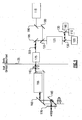
- FIG. 1 there is illustrated a block diagram of one example of a multi-function gimbaled optical sensor system 100 in which a jitter sensing mechanism according to various embodiments may be implemented.
- the system 100 may be mounted on an aircraft, for example, or other mobile platform.
- the system 100 includes passive sensors, for example, an infrared (IR) focal plane array 105 and a visible focal plane array 110, and active sensors, for example, a laser transmit/receive module 115.
- Laser beam steering mirrors 180 may be used to guide optical beams to and from the active sensors, such as the laser transmit/receive module 115.
- a dichroic beam splitter 120 is used to separate the optical paths for the passive sensors and the active sensors.
- the passive path includes a relayed imager 125, and additional dichroic beam splitters 130 are used to direct the optical beams to the various passive sensors.
- components to the left of line 135 are gimbal-mounted; whereas components to the right of line 135 are off-gimbal and body-mounted on the aircraft.
- the gimbaled components of the system 100 may include afocal foreoptics 155 and pointing mirrors 160, 165.
- Optical beams pass via a window 170 from the pointing mirrors 160, 165 to object space, and vice versa.
- a beam-steering mirror 195 is used to steer the line of sight of the sensors, as discussed further below.
- FIG. 2 illustrates a ray trace of the passive sensor optical path through the system of FIG. 1 operating in a forward step-stare mode (i.e., the line of sight of the system is along the roll axis, in the direction of travel of the aircraft). It is to be appreciated that the system 100 may also be operated in other modes, for example, in an elevation stare-track mode or in a side-looking stare-track mode.
- focal point 210 corresponds to the focal plane array of at least one passive sensor (e.g., IR focal plane array 105 or visible focal plane array 110).
- the opto-mechanical assembly of the system 100 includes a three-axis gimbal, having a roll axis (represented by arrow 140) aligned with the direction of travel of the aircraft, an azimuth axis 145, and an elevation axis 150.
- the roll and azimuth axes may introduce image rotation to the images constructed from optical beams received by the optical sensor system 100.
- the system 100 may include a derotation device 175, for example, a derotation prism, to compensate for this image rotation.
- the opto-mechanical assembly may be configured to sweep the fields of view of the sensors over a wide range of azimuth angles, for example, approximately -80°to 80°, and over a smaller range of elevation angles, for example, approximately ⁇ 10° or ⁇ 20°.
- movement on the roll axis may sweep fields of view of the sensors over a wide range of roll angles.
- the system 100 can point the fields of view of the active and passive sensors over a very large field of regard, as discussed above.
- the fields of view of the sensors may be very small.
- the visual focal plane array 110 may have a field of view of approximately 2.5 degrees, with an individual pixel subtending 23 microradians ( ⁇ rad) and the infrared focal plane array 105 may have a field of view of approximately 2.5 degrees, with an individual pixel subtending 45 ⁇ rad.
- the visual focal plane array 110 may have a field of view of approximately 2.5 degrees and an individual pixel subtending 12 ⁇ rad and the infrared focal plane array 105 may have a field of view of approximately 2.5 degrees and an individual pixel subtending 30 ⁇ rad.
- very precise jitter control for example, approximately 8 ⁇ rad, 4-5 ⁇ rad or 2-4 ⁇ rad, may be desirable.
- a double-pass jitter sensing technique is used for line-of-sight jitter sensing in the optical sensor system 100.
- the jitter sensing beam 320 travels through the optical components of the system 100 along the sensor line of sight, jitter on the jitter sensing beam is the same as jitter on the line of sight. Accordingly, error signals generated from the jitter sensing measurements taken using the jitter sensing beam may be used to apply corrections to the beam-steering mirror 195, as discussed above.
- the use of a double-pass jitter sensing technique may allow both the source of jitter sensing beam and the jitter sensing detector to be located off-gimbal and body-mounted on the aircraft (i.e., to the right of line 135 in FIG. 1 ). Additionally, the use of a double-pass jitter sensing technique may allow the return beam to be interfered with a coherent phase reference and form an interferometer, such that absolute changes in optical path length can be additionally sensed. The sensing of such changes in optical path length may be desirable for certain advanced coherent detection Lidar subsystems.
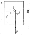
- the optical system 100 includes a jitter sensing module 190.
- the jitter sensing beam source 220 and jitter sensing detector 230 for jitter control can both be located within module 190.
- the jitter sensing beam 320 from the beam source 220 comes out of module 190, travels forward through all optical elements, reflects off a faceted retro-mirror 410, as discussed further below, and returns to module 190 by the same path to the sensing detector 230.
- a beam splitter 240 may be used to separate the forward and return optical paths of the jitter sensing beam 320 within the module 190.
- the elevation axis is the inner-most axis of the three-axis gimbal.
- a mirror 410 located out of plane with the elevation mirror 160 may be used to return the jitter sensing beam 320 to the jitter sensing detector 230 within module 190 to provide jitter sensing measurements.
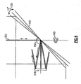
- the elevation axis 150 steers the sensor line of sight at twice the rate of movement of the elevation mirror 160, whereas the azimuth 145 and roll 140 axes steer the sensor line of sight at the same rate as the mirror or gimbal. As a result, referring to FIG.
- angular movement of the elevation mirror 160 may quickly cause the retro-reflected beam to fall outside of the field of view of the jitter sensing detector 230 within module 190, as illustrated in FIG. 4 .
- ⁇ 5° angular travel 330 of the elevation mirror 160 results in ⁇ 10° travel of the jitter sensing beam 320, which may result in the retro-reflected beam not being returned to the jitter sensing detector 230 within module 190.
- the flat mirror 310 is replaced with a faceted retro-mirror 410.
- the faceted retro-mirror 410 is located on the object space side of the inner-most gimbal axis.
- the inner-most gimbal axis is the elevation axis 150.
- the elevation mirror 160 may be a 2:1 gain flex-pivoted flat fold mirror.
- the faceted retro-mirror 410 includes a reflective face that is formed with a plurality of facets 420, each angled slightly with respect to adjacent facets.
- the faceted retro-mirror 410 is rigidly mounted on the azimuth axis 145 of the gimbal such that the mirror moves with movement of the azimuth axis but does not move in elevation as the elevation mirror 160 is actuated. Accordingly, angular movement 330 of the elevation mirror 160 causes the jitter sensing beam to translate from facet to facet of the faceted retro-mirror 410.
- the tilt angle of each facet 420 may differ from that of its nearest neighbor facet by a specified number of degrees, for example, one degree (1°).
- the faceted retro-mirror 410 may be designed with facets that are angled with respect to one another by an amount other than 1°. For example, the difference between the angles of the facets may be selected based on a desired size of the mirror 410, number of facets 420, and/or expected range of angular motion of the elevation mirror 160.
- the faceted retro-mirror 410 removes the line of sight bias from the jitter sensing beam and allows the beam to stay within the field of view of the jitter sensing detector 230 for jitter sensing.
- This mechanism allows for accurate line of sight jitter sensing because the jitter sensing beam double-passes and samples all optical surfaces in the line of sight optical path.
- Conventional jitter-sensing mechanisms may exclude one or more optical surfaces and hence compromise the accuracy of the monitoring process.
- the jitter sensing detector 230 includes a photodetector 510, such as a photo-potentiometer ("photopot") or position sensitive detector (PSD) that detects the incident jitter sensing beam.
- the faceted retro-mirror 410 includes a plurality of facets 420 with a central flat facet and the facets above and below the central facet tilted by 1° degree relative to one another.
- the jitter sensing beam is reflected by the center facet 420 of the faceted retro-mirror, and the reflected beam (referred to as the 0° facet return 520) is centered on the photodetector 510, as illustrated in the first (left-most) panel of FIG. 6 .
- the +1° facet return 530 i.e., beam reflected by the facet immediately below the central facet
- -1° facet return 540 i.e., beam reflected by the facet immediately above the central facet
- both are returned outside the field of view of the photodetector 510.
- the photodetector 510 detects the jitter sensing beam based on the 0° facet return 520.
- FIG. 6 illustrates the shifting of the 0°, +1° and -1° facet returns 520, 530 and 540, respectively, on the photodetector 510 as the line of sight of the system 100 (and therefore the jitter sensing beam 320) is moved by actuation of the elevation mirror 160.
- a one degree movement in the line of sight (corresponding to a 0.5 degree movement of the elevation mirror 160) causes the jitter sensing beam to translate completely to the adjacent facet and returns the beam to the center of the photodetector 510.
- the faceted retro-mirror 410 (moving on the azimuth axis 145) periodically returns the jitter sensing beam to the center of the jitter sensing detector 230 field of view.
- the faceted retro-mirror 410 removes the absolute elevation angle from the beam, modulo 1° (or another amount, based on the angle of separation between adjacent facets), yet retains the line of sight jitter information in both the azimuth and elevation dimensions unperturbed for accurate jitter sensing and corrections.
- the diameter of the jitter sensing beam may be larger than the individual mirror facets 420. Therefore, multiple jitter sensing beam returns may be generated by adjacent mirror facets 420, as discussed above and illustrated in FIG. 6 .
- the photodetector 510 is a pixilated imaging array sensitive to the wavelength of the jitter sensing beam. Using this type of sensing detector, the presence of two or more beams is easily distinguished and the desired jitter measurement signal is easily determined.
- the photodetector 510 is a single position centroid sensing photodetector, also known as a photopot, that is sensitive to the wavelength of the jitter sensing beam. These types of detectors are configured to determine the centroid of incident light (from one or more beams) Dotted circle 550 represents the centroid of the returned jitter sensing beam 320. As can be seen with reference to FIG. 6 , in some circumstances, multiple facet returns may be incident on the photodetector 510 at the same time, which may result in some sensing ambiguity.
- the position centroid sensing photodetectors may be configured to handle such ambiguities, the ambiguities may cause a loss of resolution in the jitter measurements, and therefore may be undesirable in embodiments where the jitter sensing and compensation requirement is only a few microradians. As discussed above, this ambiguity may be negated by the use of a pixilated imaging array for the photodetector 510.
- the faceted retro-mirror 410 is configured with each facet 420 also having a fixed azimuth angle bias.
- the jitter sensing detector 230 includes at least two photodetectors arranged side-by-side, as illustrated for example in FIG. 7 .
- the facets have alternating + and - azimuth tilts to separate the facet returns 520, 530 or 540.
- the fixed azimuth angles biases or tilts of the facets may be selected such that only a single facet return 520, 530 or 540 falls on either one of the pair of photodetectors 560a, 560b at any given time, as shown in FIG. 7 .
- the fixed azimuth angle biases of the facets 420 may be substantially smaller than the facet angles.
- the facet angles may be approximately 1° from one facet to an adjacent facet, whereas the azimuth angle biases may be only a fraction of a degree, for example, about one half of a degree.
- the azimuth angle biases need only be sufficient to separate the facet returns such that adjacent facet returns fall on different photodetectors (e.g., 560a or 560b) at any given time.
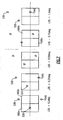
- FIG. 8A is a schematic front view of one example of a faceted retro-mirror 410a without alternating azimuth tilts.
- the arrows represent facet normals.
- FIG. 8B is a schematic side view of an example of the faceted retro-mirror 410
- FIG. 8C is a schematic front view of one example of a faceted retro-mirror 410b having alternating azimuth tilts, as discussed above.
- the arrows represent facet normals.
Landscapes
- Physics & Mathematics (AREA)
- General Physics & Mathematics (AREA)
- Optics & Photonics (AREA)
- Engineering & Computer Science (AREA)
- Multimedia (AREA)
- Signal Processing (AREA)
- Optical Radar Systems And Details Thereof (AREA)
Claims (15)
- Kardanisch aufgehängtes optisches Sensorsystem (100) mit
einem mehrachsigen kardanischen Rahmen,
einer Jittermessstrahlquelle (220), die ausgebildet ist, um einen Jittermessstrahl (320) zu erzeugen, der sich entlang einer Sichtlinie des kardanisch aufgehängten optischen Sensorsystems (100) ausbreitet,
einem Jittermessstrahldetektor (230),
einem flachen Spiegel (160), der an einer innersten Kardanachse (150) des mehrachsigen kardanischen Rahmen montiert und ausgebildet ist, um den Jittermessstrahl (320) zu reflektieren, und
einem facettierten Rückspiegel (410), der fest an einer zweiten Kardanachse (145) des mehrachsigen kardanischen Rahmens montiert ist und nicht in einer Ebene mit dem flachen Spiegel positioniert ist und ausgerichtet ist, um den vom flachen Spiegel reflektierten Jittermessstrahl (320) zu empfangen, wobei der facettierte Rückspiegel eine Mehrzahl von Facetten (420) aufweist, die jeweils relativ zu benachbarten Facetten um einen Neigungswinkel geneigt sind, wobei der facettierte Rückspiegel ausgebildet ist, um den Jittermessstrahl von zumindest einer Facette des facettierten Rückspiegels (410) über den flachen Spiegel (160) in ein Sichtfeld des Jittermessstrahldetektors (230) über einen Bereich einer Winkelbewegung des flachen Spiegels (160) um die innerste Kardanachse zu reflektieren. - Kardanisch aufgehängtes optisches Sensorsystem (100) nach Anspruch 1, wobei die innerste Kardanachse (150) eine Elevationsachse ist und die zweite Kardanachse (145) eine Azimuthachse ist.
- Kardanisch aufgehängtes optisches Sensorsystem (100) nach Anspruch 1 oder 2, bei dem der Neigungswinkel der benachbarten Facetten ungefähr 1° in Elevation ist.
- Kardanisch aufgehängtes optisches Sensorsystem (100) nach Anspruch 1, 2 oder 3, bei dem der Jittermessstrahldetektor (230) einen Positionsschwerpunktsmessfotodetektor (510) aufweist.
- Kardanisch aufgehängtes optisches Sensorsystem (100) nach einem der vorhergehenden Ansprüche, bei dem der Jittermessstrahldetektor (230) einen pixelierten Abbildungsbereich aufweist.
- Kardanisch aufgehängtes optisches Sensorsystem (100) nach einem der vorhergehenden Ansprüche, bei dem der Bereich der Winkelbewegung des flachen Spiegels ungefähr ± 5° beträgt.
- Kardanisch aufgehängtes optisches Sensorsystem (100) nach einem der Ansprüche 1 bis 5, bei dem der Bereich der Winkelbewegung des flachen Spiegels (110) ungefähr ± 10° beträgt.
- Kardanisch aufgehängtes optisches Sensorsystem (100) nach einem der vorhergehenden Ansprüche, bei dem jede Facette der Mehrzahl von Facetten ferner eine wechselnde Azimuthneigung aufweist.
- Kardanisch aufgehängtes optisches Sensorsystem (100) nach Anspruch 8, bei dem der Jittermessstrahldetektor (230) zwei Seite an Seite positionierte Fotodetektoren (560a, 560b) aufweist, und bei dem die wechselnde Azimuthneigung jeder Facette so gewählt ist, dass jede Facette den Jittermessstrahl zu nur einer der beiden Fotodetektoren (560a, 560b) reflektiert.
- Kardanisch aufgehängtes optisches Sensorsystem (100) nach einem der vorhergehenden Ansprüche, bei dem der flache Spiegel (160) und der facettierte Rückspiegel (410) in einer optomechanischen Anordnung enthalten sind, wobei der flache Spiegel (160) an einer Elevationsachse der optomechanischen Anordnung montiert ist und der facettierte Rückspiegel an einer Azimuthachse der optomechanischen Anordnung montiert ist, wobei die optomechanische Anordnung ausgebildet ist, um den flachen Spiegel (160) über den Bereich der Winkelbewegung zu bewegen.
- Kardanisch aufgehängtes optisches Sensorsystem (100) nach einem der vorhergehenden Ansprüche, bei dem der flache Spiegel (160) ein flacher Spiegel mit 2:1-Verstärkung ist.
- Verfahren eines Sichtlinienjittermessens in einem kardanisch aufgehängten optischen Sensorsystem (100), das einen mehrachsigen kardanischen Rahmen aufweist, wobei das Verfahren folgende Schritte aufweist:Erzeugen eines Jittermessstrahls (320) undRichten des Jittermessstrahls (320) entlang einer Sichtlinie des kardanisch aufgehängten optischen Sensorsystems (100),Reflektieren des Jittermessstrahls (320) von einem flachen Spiegel (160) zu einem facettierten Rückspiegel (410), der nicht in einer Ebene mit dem flachen Spiegel (160) positioniert ist, wobei der flache Spiegel (160) an einer innersten Kardanachse (150) des mehrachsigen kardanischen Rahmens montiert ist und der facettierte Rückspiegel (410) fest an einer zweien Kardanachse des mehrachsigen kardanischen Rahmens montiert ist und ausgerichtet ist, um den vom flachen Spiegel (160) reflektierten Jittermessstrahl (320) zu empfangen, wobei der facettierte Rückspiegel (410) eine Mehrzahl von Facetten aufweist, die jeweils relativ zu benachbarten Facetten um eine Winkelneigung geneigt sind,Bewegen des flachen Spiegels (160) über einen Bereich einer Winkelbewegung um die innerste Kardanachse (150) undReflektieren des Jittermessstrahls (320) von zumindest einer Facette des facettierten Rückspiegels (410) über den flachen Spiegel (160) zu einem Sichtfeld eines Jittermessstrahldetektors (230) über den Bereich der Winkelbewegung des flachen Spiegels (160).
- Verfahren nach Anspruch 12, bei dem die Bewegung des flachen Spiegels (160) ein Bewegen des flachen Spiegels über zumindest ± 5°der Winkelbewegung enthält.
- Verfahren nach Anspruch 12, bei dem die Bewegung des flachen Spiegels ein Bewegen des flachen Spiegels (160) über zumindest ± 10° der Winkelbewegung enthält.
- Verfahren nach Anspruch 12, 13 oder 14, bei dem der flache Spiegel (160) ein flacher Spiegel mit 2:1-Verstärkung ist.
Applications Claiming Priority (1)
| Application Number | Priority Date | Filing Date | Title |
|---|---|---|---|
| US13/286,362 US8536503B2 (en) | 2011-11-01 | 2011-11-01 | Faceted retro-mirror for line-of-sight jitter sensing |
Publications (2)
| Publication Number | Publication Date |
|---|---|
| EP2590005A1 EP2590005A1 (de) | 2013-05-08 |
| EP2590005B1 true EP2590005B1 (de) | 2015-02-25 |
Family
ID=45655318
Family Applications (1)
| Application Number | Title | Priority Date | Filing Date |
|---|---|---|---|
| EP12153209.7A Active EP2590005B1 (de) | 2011-11-01 | 2012-01-31 | Facettierter Rückspiegel für Sichtlinien-Jittermessung |
Country Status (3)
| Country | Link |
|---|---|
| US (1) | US8536503B2 (de) |
| EP (1) | EP2590005B1 (de) |
| IL (1) | IL217508A0 (de) |
Families Citing this family (10)
| Publication number | Priority date | Publication date | Assignee | Title |
|---|---|---|---|---|
| US9404792B2 (en) | 2013-07-01 | 2016-08-02 | Raytheon Company | Auto-alignment system for high precision masted head mirror |
| US9841607B2 (en) * | 2015-05-01 | 2017-12-12 | The Boeing Company | Method and apparatus for stabilizing a line of sight of a radiant energy system |
| US9601904B1 (en) | 2015-12-07 | 2017-03-21 | Raytheon Company | Laser diode driver with variable input voltage and variable diode string voltage |
| US10567654B2 (en) | 2017-04-27 | 2020-02-18 | Raytheon Company | Automatic structurally induced line of sight jitter compensation for electro-optical/infrared turret system |
| US11830194B2 (en) | 2019-06-27 | 2023-11-28 | Massachusetts Institute Of Technology | Data-driven angular jitter estimator for lidar |
| US11619709B2 (en) * | 2020-04-20 | 2023-04-04 | Raytheon Company | Optical system to reduce local internal backscatter |
| US11754680B2 (en) | 2020-04-20 | 2023-09-12 | Raytheon Company | Optical system that detects and blocks backscatter |
| US11268860B2 (en) | 2020-07-24 | 2022-03-08 | Raytheon Company | Radiometric calibration of detector |
| US11363198B2 (en) * | 2020-10-07 | 2022-06-14 | Raytheon Company | Optical sensor with jitter stabiliization |
| US12038609B2 (en) * | 2021-09-03 | 2024-07-16 | Raytheon Company | Diffraction grating return mirror for wide field of view line of sight jitter sensing |
Family Cites Families (5)
| Publication number | Priority date | Publication date | Assignee | Title |
|---|---|---|---|---|
| US4010365A (en) | 1973-03-26 | 1977-03-01 | Hughes Aircraft Company | Self-stabilizing image scanner |
| US4445140A (en) * | 1981-12-29 | 1984-04-24 | Honeywell Inc. | Electronic image stabilization system |
| US4701602A (en) * | 1984-08-02 | 1987-10-20 | Hughes Aircraft Company | Adaptable modular stabilization system |
| US6653611B2 (en) * | 2001-04-09 | 2003-11-25 | A-Tech Corporation | Optical line of sight pointing and stabilization system |
| US7876359B2 (en) | 2003-01-17 | 2011-01-25 | Insitu, Inc. | Cooperative nesting of mechanical and electronic stabilization for an airborne camera system |
-
2011
- 2011-11-01 US US13/286,362 patent/US8536503B2/en active Active
-
2012
- 2012-01-12 IL IL217508A patent/IL217508A0/en active IP Right Grant
- 2012-01-31 EP EP12153209.7A patent/EP2590005B1/de active Active
Also Published As
| Publication number | Publication date |
|---|---|
| EP2590005A1 (de) | 2013-05-08 |
| US8536503B2 (en) | 2013-09-17 |
| IL217508A0 (en) | 2012-06-28 |
| US20130105671A1 (en) | 2013-05-02 |
Similar Documents
| Publication | Publication Date | Title |
|---|---|---|
| EP2590005B1 (de) | Facettierter Rückspiegel für Sichtlinien-Jittermessung | |
| EP3025183B1 (de) | Vierachsiger kardan-flugzeugsensor | |
| EP2525235B1 (de) | Luftgestütztes multifunktionales Sensorsystem | |
| US11774557B2 (en) | Distance measurement instrument with scanning function | |
| EP3017266B1 (de) | Selbstausrichtungssystem für hochpräzisen stirnspiegel mit mast | |
| EP2831624B1 (de) | Koordinatenmesssystem und -verfahren | |
| US20080073484A1 (en) | Optical system | |
| EP2588917B1 (de) | Sichtstabilisierungssystem | |
| EP2352966B1 (de) | Kardansystem mit optischem coudé-pfad und datenübertragungsverfahren | |
| KR102663862B1 (ko) | 섬유 팁 리이미징을 갖는 라이다 시스템 | |
| JP5239007B2 (ja) | 横方向及び長手方向の計測学システム | |
| KR102209500B1 (ko) | 라이다 장치 | |
| US20150069216A1 (en) | Laser beam control system with bidirectional beam director | |
| US10073165B2 (en) | Distance measurement instrument with scanning function | |
| JP7536666B2 (ja) | 測量装置 | |
| JP7344732B2 (ja) | 測量装置及び測量装置システム | |
| RU2372628C1 (ru) | Многофункциональная оптико-локационная система | |
| EP1579262A2 (de) | Optisches system | |
| US12061334B2 (en) | Optical scanning system using micro-electro-mechanical system (mems) micro-mirror arrays (MMAs) | |
| RU2541494C1 (ru) | Комбинированная оптико-электронная система | |
| US11363198B2 (en) | Optical sensor with jitter stabiliization | |
| RU2653158C1 (ru) | Локационный оптико-электронный модуль | |
| WO2023033915A1 (en) | Diffraction grating return mirror for wide field of view line of sight jitter sensing |
Legal Events
| Date | Code | Title | Description |
|---|---|---|---|
| PUAI | Public reference made under article 153(3) epc to a published international application that has entered the european phase |
Free format text: ORIGINAL CODE: 0009012 |
|
| AK | Designated contracting states |
Kind code of ref document: A1 Designated state(s): AL AT BE BG CH CY CZ DE DK EE ES FI FR GB GR HR HU IE IS IT LI LT LU LV MC MK MT NL NO PL PT RO RS SE SI SK SM TR |
|
| AX | Request for extension of the european patent |
Extension state: BA ME |
|
| 17P | Request for examination filed |
Effective date: 20130808 |
|
| RBV | Designated contracting states (corrected) |
Designated state(s): AL AT BE BG CH CY CZ DE DK EE ES FI FR GB GR HR HU IE IS IT LI LT LU LV MC MK MT NL NO PL PT RO RS SE SI SK SM TR |
|
| GRAP | Despatch of communication of intention to grant a patent |
Free format text: ORIGINAL CODE: EPIDOSNIGR1 |
|
| INTG | Intention to grant announced |
Effective date: 20140808 |
|
| GRAP | Despatch of communication of intention to grant a patent |
Free format text: ORIGINAL CODE: EPIDOSNIGR1 |
|
| INTG | Intention to grant announced |
Effective date: 20141211 |
|
| GRAS | Grant fee paid |
Free format text: ORIGINAL CODE: EPIDOSNIGR3 |
|
| GRAA | (expected) grant |
Free format text: ORIGINAL CODE: 0009210 |
|
| AK | Designated contracting states |
Kind code of ref document: B1 Designated state(s): AL AT BE BG CH CY CZ DE DK EE ES FI FR GB GR HR HU IE IS IT LI LT LU LV MC MK MT NL NO PL PT RO RS SE SI SK SM TR |
|
| REG | Reference to a national code |
Ref country code: GB Ref legal event code: FG4D |
|
| REG | Reference to a national code |
Ref country code: CH Ref legal event code: EP |
|
| REG | Reference to a national code |
Ref country code: IE Ref legal event code: FG4D |
|
| REG | Reference to a national code |
Ref country code: DE Ref legal event code: R096 Ref document number: 602012005345 Country of ref document: DE Effective date: 20150402 |
|
| REG | Reference to a national code |
Ref country code: AT Ref legal event code: REF Ref document number: 712460 Country of ref document: AT Kind code of ref document: T Effective date: 20150415 |
|
| REG | Reference to a national code |
Ref country code: NL Ref legal event code: VDEP Effective date: 20150225 |
|
| REG | Reference to a national code |
Ref country code: AT Ref legal event code: MK05 Ref document number: 712460 Country of ref document: AT Kind code of ref document: T Effective date: 20150225 |
|
| REG | Reference to a national code |
Ref country code: LT Ref legal event code: MG4D |
|
| PG25 | Lapsed in a contracting state [announced via postgrant information from national office to epo] |
Ref country code: SE Free format text: LAPSE BECAUSE OF FAILURE TO SUBMIT A TRANSLATION OF THE DESCRIPTION OR TO PAY THE FEE WITHIN THE PRESCRIBED TIME-LIMIT Effective date: 20150225 Ref country code: LT Free format text: LAPSE BECAUSE OF FAILURE TO SUBMIT A TRANSLATION OF THE DESCRIPTION OR TO PAY THE FEE WITHIN THE PRESCRIBED TIME-LIMIT Effective date: 20150225 Ref country code: HR Free format text: LAPSE BECAUSE OF FAILURE TO SUBMIT A TRANSLATION OF THE DESCRIPTION OR TO PAY THE FEE WITHIN THE PRESCRIBED TIME-LIMIT Effective date: 20150225 Ref country code: FI Free format text: LAPSE BECAUSE OF FAILURE TO SUBMIT A TRANSLATION OF THE DESCRIPTION OR TO PAY THE FEE WITHIN THE PRESCRIBED TIME-LIMIT Effective date: 20150225 Ref country code: NO Free format text: LAPSE BECAUSE OF FAILURE TO SUBMIT A TRANSLATION OF THE DESCRIPTION OR TO PAY THE FEE WITHIN THE PRESCRIBED TIME-LIMIT Effective date: 20150525 Ref country code: ES Free format text: LAPSE BECAUSE OF FAILURE TO SUBMIT A TRANSLATION OF THE DESCRIPTION OR TO PAY THE FEE WITHIN THE PRESCRIBED TIME-LIMIT Effective date: 20150225 |
|
| PG25 | Lapsed in a contracting state [announced via postgrant information from national office to epo] |
Ref country code: GR Free format text: LAPSE BECAUSE OF FAILURE TO SUBMIT A TRANSLATION OF THE DESCRIPTION OR TO PAY THE FEE WITHIN THE PRESCRIBED TIME-LIMIT Effective date: 20150526 Ref country code: IS Free format text: LAPSE BECAUSE OF FAILURE TO SUBMIT A TRANSLATION OF THE DESCRIPTION OR TO PAY THE FEE WITHIN THE PRESCRIBED TIME-LIMIT Effective date: 20150625 Ref country code: RS Free format text: LAPSE BECAUSE OF FAILURE TO SUBMIT A TRANSLATION OF THE DESCRIPTION OR TO PAY THE FEE WITHIN THE PRESCRIBED TIME-LIMIT Effective date: 20150225 Ref country code: LV Free format text: LAPSE BECAUSE OF FAILURE TO SUBMIT A TRANSLATION OF THE DESCRIPTION OR TO PAY THE FEE WITHIN THE PRESCRIBED TIME-LIMIT Effective date: 20150225 Ref country code: AT Free format text: LAPSE BECAUSE OF FAILURE TO SUBMIT A TRANSLATION OF THE DESCRIPTION OR TO PAY THE FEE WITHIN THE PRESCRIBED TIME-LIMIT Effective date: 20150225 |
|
| PG25 | Lapsed in a contracting state [announced via postgrant information from national office to epo] |
Ref country code: NL Free format text: LAPSE BECAUSE OF FAILURE TO SUBMIT A TRANSLATION OF THE DESCRIPTION OR TO PAY THE FEE WITHIN THE PRESCRIBED TIME-LIMIT Effective date: 20150225 |
|
| PG25 | Lapsed in a contracting state [announced via postgrant information from national office to epo] |
Ref country code: DK Free format text: LAPSE BECAUSE OF FAILURE TO SUBMIT A TRANSLATION OF THE DESCRIPTION OR TO PAY THE FEE WITHIN THE PRESCRIBED TIME-LIMIT Effective date: 20150225 Ref country code: EE Free format text: LAPSE BECAUSE OF FAILURE TO SUBMIT A TRANSLATION OF THE DESCRIPTION OR TO PAY THE FEE WITHIN THE PRESCRIBED TIME-LIMIT Effective date: 20150225 Ref country code: SK Free format text: LAPSE BECAUSE OF FAILURE TO SUBMIT A TRANSLATION OF THE DESCRIPTION OR TO PAY THE FEE WITHIN THE PRESCRIBED TIME-LIMIT Effective date: 20150225 Ref country code: CZ Free format text: LAPSE BECAUSE OF FAILURE TO SUBMIT A TRANSLATION OF THE DESCRIPTION OR TO PAY THE FEE WITHIN THE PRESCRIBED TIME-LIMIT Effective date: 20150225 Ref country code: RO Free format text: LAPSE BECAUSE OF FAILURE TO SUBMIT A TRANSLATION OF THE DESCRIPTION OR TO PAY THE FEE WITHIN THE PRESCRIBED TIME-LIMIT Effective date: 20150225 |
|
| REG | Reference to a national code |
Ref country code: DE Ref legal event code: R097 Ref document number: 602012005345 Country of ref document: DE |
|
| PG25 | Lapsed in a contracting state [announced via postgrant information from national office to epo] |
Ref country code: PL Free format text: LAPSE BECAUSE OF FAILURE TO SUBMIT A TRANSLATION OF THE DESCRIPTION OR TO PAY THE FEE WITHIN THE PRESCRIBED TIME-LIMIT Effective date: 20150225 |
|
| REG | Reference to a national code |
Ref country code: FR Ref legal event code: PLFP Year of fee payment: 5 |
|
| PG25 | Lapsed in a contracting state [announced via postgrant information from national office to epo] |
Ref country code: IT Free format text: LAPSE BECAUSE OF FAILURE TO SUBMIT A TRANSLATION OF THE DESCRIPTION OR TO PAY THE FEE WITHIN THE PRESCRIBED TIME-LIMIT Effective date: 20150225 |
|
| PLBE | No opposition filed within time limit |
Free format text: ORIGINAL CODE: 0009261 |
|
| STAA | Information on the status of an ep patent application or granted ep patent |
Free format text: STATUS: NO OPPOSITION FILED WITHIN TIME LIMIT |
|
| 26N | No opposition filed |
Effective date: 20151126 |
|
| PG25 | Lapsed in a contracting state [announced via postgrant information from national office to epo] |
Ref country code: SI Free format text: LAPSE BECAUSE OF FAILURE TO SUBMIT A TRANSLATION OF THE DESCRIPTION OR TO PAY THE FEE WITHIN THE PRESCRIBED TIME-LIMIT Effective date: 20150225 |
|
| PG25 | Lapsed in a contracting state [announced via postgrant information from national office to epo] |
Ref country code: BE Free format text: LAPSE BECAUSE OF FAILURE TO SUBMIT A TRANSLATION OF THE DESCRIPTION OR TO PAY THE FEE WITHIN THE PRESCRIBED TIME-LIMIT Effective date: 20150225 |
|
| PG25 | Lapsed in a contracting state [announced via postgrant information from national office to epo] |
Ref country code: LU Free format text: LAPSE BECAUSE OF FAILURE TO SUBMIT A TRANSLATION OF THE DESCRIPTION OR TO PAY THE FEE WITHIN THE PRESCRIBED TIME-LIMIT Effective date: 20160131 |
|
| REG | Reference to a national code |
Ref country code: CH Ref legal event code: PL |
|
| PG25 | Lapsed in a contracting state [announced via postgrant information from national office to epo] |
Ref country code: MC Free format text: LAPSE BECAUSE OF FAILURE TO SUBMIT A TRANSLATION OF THE DESCRIPTION OR TO PAY THE FEE WITHIN THE PRESCRIBED TIME-LIMIT Effective date: 20150225 |
|
| PG25 | Lapsed in a contracting state [announced via postgrant information from national office to epo] |
Ref country code: LI Free format text: LAPSE BECAUSE OF NON-PAYMENT OF DUE FEES Effective date: 20160131 Ref country code: CH Free format text: LAPSE BECAUSE OF NON-PAYMENT OF DUE FEES Effective date: 20160131 |
|
| REG | Reference to a national code |
Ref country code: IE Ref legal event code: MM4A |
|
| REG | Reference to a national code |
Ref country code: FR Ref legal event code: PLFP Year of fee payment: 6 |
|
| PG25 | Lapsed in a contracting state [announced via postgrant information from national office to epo] |
Ref country code: IE Free format text: LAPSE BECAUSE OF NON-PAYMENT OF DUE FEES Effective date: 20160131 |
|
| PG25 | Lapsed in a contracting state [announced via postgrant information from national office to epo] |
Ref country code: MT Free format text: LAPSE BECAUSE OF FAILURE TO SUBMIT A TRANSLATION OF THE DESCRIPTION OR TO PAY THE FEE WITHIN THE PRESCRIBED TIME-LIMIT Effective date: 20150225 |
|
| REG | Reference to a national code |
Ref country code: FR Ref legal event code: PLFP Year of fee payment: 7 |
|
| PG25 | Lapsed in a contracting state [announced via postgrant information from national office to epo] |
Ref country code: CY Free format text: LAPSE BECAUSE OF FAILURE TO SUBMIT A TRANSLATION OF THE DESCRIPTION OR TO PAY THE FEE WITHIN THE PRESCRIBED TIME-LIMIT Effective date: 20150225 Ref country code: SM Free format text: LAPSE BECAUSE OF FAILURE TO SUBMIT A TRANSLATION OF THE DESCRIPTION OR TO PAY THE FEE WITHIN THE PRESCRIBED TIME-LIMIT Effective date: 20150225 Ref country code: HU Free format text: LAPSE BECAUSE OF FAILURE TO SUBMIT A TRANSLATION OF THE DESCRIPTION OR TO PAY THE FEE WITHIN THE PRESCRIBED TIME-LIMIT; INVALID AB INITIO Effective date: 20120131 |
|
| PG25 | Lapsed in a contracting state [announced via postgrant information from national office to epo] |
Ref country code: TR Free format text: LAPSE BECAUSE OF FAILURE TO SUBMIT A TRANSLATION OF THE DESCRIPTION OR TO PAY THE FEE WITHIN THE PRESCRIBED TIME-LIMIT Effective date: 20150225 Ref country code: PT Free format text: LAPSE BECAUSE OF FAILURE TO SUBMIT A TRANSLATION OF THE DESCRIPTION OR TO PAY THE FEE WITHIN THE PRESCRIBED TIME-LIMIT Effective date: 20150225 Ref country code: MK Free format text: LAPSE BECAUSE OF FAILURE TO SUBMIT A TRANSLATION OF THE DESCRIPTION OR TO PAY THE FEE WITHIN THE PRESCRIBED TIME-LIMIT Effective date: 20150225 |
|
| PG25 | Lapsed in a contracting state [announced via postgrant information from national office to epo] |
Ref country code: BG Free format text: LAPSE BECAUSE OF FAILURE TO SUBMIT A TRANSLATION OF THE DESCRIPTION OR TO PAY THE FEE WITHIN THE PRESCRIBED TIME-LIMIT Effective date: 20150225 |
|
| PG25 | Lapsed in a contracting state [announced via postgrant information from national office to epo] |
Ref country code: AL Free format text: LAPSE BECAUSE OF FAILURE TO SUBMIT A TRANSLATION OF THE DESCRIPTION OR TO PAY THE FEE WITHIN THE PRESCRIBED TIME-LIMIT Effective date: 20150225 |
|
| P01 | Opt-out of the competence of the unified patent court (upc) registered |
Effective date: 20230530 |
|
| PGFP | Annual fee paid to national office [announced via postgrant information from national office to epo] |
Ref country code: DE Payment date: 20241218 Year of fee payment: 14 |
|
| PGFP | Annual fee paid to national office [announced via postgrant information from national office to epo] |
Ref country code: GB Payment date: 20251220 Year of fee payment: 15 |
|
| PGFP | Annual fee paid to national office [announced via postgrant information from national office to epo] |
Ref country code: FR Payment date: 20251217 Year of fee payment: 15 |