EP2589896A2 - Air Conditioner - Google Patents
Air Conditioner Download PDFInfo
- Publication number
- EP2589896A2 EP2589896A2 EP12161518.1A EP12161518A EP2589896A2 EP 2589896 A2 EP2589896 A2 EP 2589896A2 EP 12161518 A EP12161518 A EP 12161518A EP 2589896 A2 EP2589896 A2 EP 2589896A2
- Authority
- EP
- European Patent Office
- Prior art keywords
- heat exchanger
- outdoor
- defrosting operation
- air conditioner
- units
- Prior art date
- Legal status (The legal status is an assumption and is not a legal conclusion. Google has not performed a legal analysis and makes no representation as to the accuracy of the status listed.)
- Granted
Links
Images


Classifications
-
- F—MECHANICAL ENGINEERING; LIGHTING; HEATING; WEAPONS; BLASTING
- F25—REFRIGERATION OR COOLING; COMBINED HEATING AND REFRIGERATION SYSTEMS; HEAT PUMP SYSTEMS; MANUFACTURE OR STORAGE OF ICE; LIQUEFACTION SOLIDIFICATION OF GASES
- F25B—REFRIGERATION MACHINES, PLANTS OR SYSTEMS; COMBINED HEATING AND REFRIGERATION SYSTEMS; HEAT PUMP SYSTEMS
- F25B47/00—Arrangements for preventing or removing deposits or corrosion, not provided for in another subclass
- F25B47/02—Defrosting cycles
-
- F—MECHANICAL ENGINEERING; LIGHTING; HEATING; WEAPONS; BLASTING
- F25—REFRIGERATION OR COOLING; COMBINED HEATING AND REFRIGERATION SYSTEMS; HEAT PUMP SYSTEMS; MANUFACTURE OR STORAGE OF ICE; LIQUEFACTION SOLIDIFICATION OF GASES
- F25B—REFRIGERATION MACHINES, PLANTS OR SYSTEMS; COMBINED HEATING AND REFRIGERATION SYSTEMS; HEAT PUMP SYSTEMS
- F25B13/00—Compression machines, plants or systems, with reversible cycle
-
- F—MECHANICAL ENGINEERING; LIGHTING; HEATING; WEAPONS; BLASTING
- F25—REFRIGERATION OR COOLING; COMBINED HEATING AND REFRIGERATION SYSTEMS; HEAT PUMP SYSTEMS; MANUFACTURE OR STORAGE OF ICE; LIQUEFACTION SOLIDIFICATION OF GASES
- F25B—REFRIGERATION MACHINES, PLANTS OR SYSTEMS; COMBINED HEATING AND REFRIGERATION SYSTEMS; HEAT PUMP SYSTEMS
- F25B47/00—Arrangements for preventing or removing deposits or corrosion, not provided for in another subclass
- F25B47/02—Defrosting cycles
- F25B47/022—Defrosting cycles hot gas defrosting
-
- F—MECHANICAL ENGINEERING; LIGHTING; HEATING; WEAPONS; BLASTING
- F25—REFRIGERATION OR COOLING; COMBINED HEATING AND REFRIGERATION SYSTEMS; HEAT PUMP SYSTEMS; MANUFACTURE OR STORAGE OF ICE; LIQUEFACTION SOLIDIFICATION OF GASES
- F25B—REFRIGERATION MACHINES, PLANTS OR SYSTEMS; COMBINED HEATING AND REFRIGERATION SYSTEMS; HEAT PUMP SYSTEMS
- F25B49/00—Arrangement or mounting of control or safety devices
- F25B49/02—Arrangement or mounting of control or safety devices for compression type machines, plants or systems
-
- F—MECHANICAL ENGINEERING; LIGHTING; HEATING; WEAPONS; BLASTING
- F25—REFRIGERATION OR COOLING; COMBINED HEATING AND REFRIGERATION SYSTEMS; HEAT PUMP SYSTEMS; MANUFACTURE OR STORAGE OF ICE; LIQUEFACTION SOLIDIFICATION OF GASES
- F25B—REFRIGERATION MACHINES, PLANTS OR SYSTEMS; COMBINED HEATING AND REFRIGERATION SYSTEMS; HEAT PUMP SYSTEMS
- F25B2313/00—Compression machines, plants or systems with reversible cycle not otherwise provided for
- F25B2313/023—Compression machines, plants or systems with reversible cycle not otherwise provided for using multiple indoor units
- F25B2313/0232—Compression machines, plants or systems with reversible cycle not otherwise provided for using multiple indoor units with bypasses
- F25B2313/02321—Compression machines, plants or systems with reversible cycle not otherwise provided for using multiple indoor units with bypasses during cooling
-
- F—MECHANICAL ENGINEERING; LIGHTING; HEATING; WEAPONS; BLASTING
- F25—REFRIGERATION OR COOLING; COMBINED HEATING AND REFRIGERATION SYSTEMS; HEAT PUMP SYSTEMS; MANUFACTURE OR STORAGE OF ICE; LIQUEFACTION SOLIDIFICATION OF GASES
- F25B—REFRIGERATION MACHINES, PLANTS OR SYSTEMS; COMBINED HEATING AND REFRIGERATION SYSTEMS; HEAT PUMP SYSTEMS
- F25B2313/00—Compression machines, plants or systems with reversible cycle not otherwise provided for
- F25B2313/025—Compression machines, plants or systems with reversible cycle not otherwise provided for using multiple outdoor units
- F25B2313/0251—Compression machines, plants or systems with reversible cycle not otherwise provided for using multiple outdoor units being defrosted alternately
-
- F—MECHANICAL ENGINEERING; LIGHTING; HEATING; WEAPONS; BLASTING
- F25—REFRIGERATION OR COOLING; COMBINED HEATING AND REFRIGERATION SYSTEMS; HEAT PUMP SYSTEMS; MANUFACTURE OR STORAGE OF ICE; LIQUEFACTION SOLIDIFICATION OF GASES
- F25B—REFRIGERATION MACHINES, PLANTS OR SYSTEMS; COMBINED HEATING AND REFRIGERATION SYSTEMS; HEAT PUMP SYSTEMS
- F25B2313/00—Compression machines, plants or systems with reversible cycle not otherwise provided for
- F25B2313/025—Compression machines, plants or systems with reversible cycle not otherwise provided for using multiple outdoor units
- F25B2313/0252—Compression machines, plants or systems with reversible cycle not otherwise provided for using multiple outdoor units with bypasses
- F25B2313/02521—Compression machines, plants or systems with reversible cycle not otherwise provided for using multiple outdoor units with bypasses during cooling
-
- F—MECHANICAL ENGINEERING; LIGHTING; HEATING; WEAPONS; BLASTING
- F25—REFRIGERATION OR COOLING; COMBINED HEATING AND REFRIGERATION SYSTEMS; HEAT PUMP SYSTEMS; MANUFACTURE OR STORAGE OF ICE; LIQUEFACTION SOLIDIFICATION OF GASES
- F25B—REFRIGERATION MACHINES, PLANTS OR SYSTEMS; COMBINED HEATING AND REFRIGERATION SYSTEMS; HEAT PUMP SYSTEMS
- F25B2313/00—Compression machines, plants or systems with reversible cycle not otherwise provided for
- F25B2313/025—Compression machines, plants or systems with reversible cycle not otherwise provided for using multiple outdoor units
- F25B2313/0252—Compression machines, plants or systems with reversible cycle not otherwise provided for using multiple outdoor units with bypasses
- F25B2313/02522—Compression machines, plants or systems with reversible cycle not otherwise provided for using multiple outdoor units with bypasses during defrosting
-
- F—MECHANICAL ENGINEERING; LIGHTING; HEATING; WEAPONS; BLASTING
- F25—REFRIGERATION OR COOLING; COMBINED HEATING AND REFRIGERATION SYSTEMS; HEAT PUMP SYSTEMS; MANUFACTURE OR STORAGE OF ICE; LIQUEFACTION SOLIDIFICATION OF GASES
- F25B—REFRIGERATION MACHINES, PLANTS OR SYSTEMS; COMBINED HEATING AND REFRIGERATION SYSTEMS; HEAT PUMP SYSTEMS
- F25B2313/00—Compression machines, plants or systems with reversible cycle not otherwise provided for
- F25B2313/025—Compression machines, plants or systems with reversible cycle not otherwise provided for using multiple outdoor units
- F25B2313/0252—Compression machines, plants or systems with reversible cycle not otherwise provided for using multiple outdoor units with bypasses
- F25B2313/02523—Compression machines, plants or systems with reversible cycle not otherwise provided for using multiple outdoor units with bypasses during heating
-
- F—MECHANICAL ENGINEERING; LIGHTING; HEATING; WEAPONS; BLASTING
- F25—REFRIGERATION OR COOLING; COMBINED HEATING AND REFRIGERATION SYSTEMS; HEAT PUMP SYSTEMS; MANUFACTURE OR STORAGE OF ICE; LIQUEFACTION SOLIDIFICATION OF GASES
- F25B—REFRIGERATION MACHINES, PLANTS OR SYSTEMS; COMBINED HEATING AND REFRIGERATION SYSTEMS; HEAT PUMP SYSTEMS
- F25B2313/00—Compression machines, plants or systems with reversible cycle not otherwise provided for
- F25B2313/025—Compression machines, plants or systems with reversible cycle not otherwise provided for using multiple outdoor units
- F25B2313/0253—Compression machines, plants or systems with reversible cycle not otherwise provided for using multiple outdoor units in parallel arrangements
- F25B2313/02531—Compression machines, plants or systems with reversible cycle not otherwise provided for using multiple outdoor units in parallel arrangements during cooling
-
- F—MECHANICAL ENGINEERING; LIGHTING; HEATING; WEAPONS; BLASTING
- F25—REFRIGERATION OR COOLING; COMBINED HEATING AND REFRIGERATION SYSTEMS; HEAT PUMP SYSTEMS; MANUFACTURE OR STORAGE OF ICE; LIQUEFACTION SOLIDIFICATION OF GASES
- F25B—REFRIGERATION MACHINES, PLANTS OR SYSTEMS; COMBINED HEATING AND REFRIGERATION SYSTEMS; HEAT PUMP SYSTEMS
- F25B2313/00—Compression machines, plants or systems with reversible cycle not otherwise provided for
- F25B2313/025—Compression machines, plants or systems with reversible cycle not otherwise provided for using multiple outdoor units
- F25B2313/0253—Compression machines, plants or systems with reversible cycle not otherwise provided for using multiple outdoor units in parallel arrangements
- F25B2313/02532—Compression machines, plants or systems with reversible cycle not otherwise provided for using multiple outdoor units in parallel arrangements during defrosting
-
- F—MECHANICAL ENGINEERING; LIGHTING; HEATING; WEAPONS; BLASTING
- F25—REFRIGERATION OR COOLING; COMBINED HEATING AND REFRIGERATION SYSTEMS; HEAT PUMP SYSTEMS; MANUFACTURE OR STORAGE OF ICE; LIQUEFACTION SOLIDIFICATION OF GASES
- F25B—REFRIGERATION MACHINES, PLANTS OR SYSTEMS; COMBINED HEATING AND REFRIGERATION SYSTEMS; HEAT PUMP SYSTEMS
- F25B2313/00—Compression machines, plants or systems with reversible cycle not otherwise provided for
- F25B2313/025—Compression machines, plants or systems with reversible cycle not otherwise provided for using multiple outdoor units
- F25B2313/0253—Compression machines, plants or systems with reversible cycle not otherwise provided for using multiple outdoor units in parallel arrangements
- F25B2313/02533—Compression machines, plants or systems with reversible cycle not otherwise provided for using multiple outdoor units in parallel arrangements during heating
-
- F—MECHANICAL ENGINEERING; LIGHTING; HEATING; WEAPONS; BLASTING
- F25—REFRIGERATION OR COOLING; COMBINED HEATING AND REFRIGERATION SYSTEMS; HEAT PUMP SYSTEMS; MANUFACTURE OR STORAGE OF ICE; LIQUEFACTION SOLIDIFICATION OF GASES
- F25B—REFRIGERATION MACHINES, PLANTS OR SYSTEMS; COMBINED HEATING AND REFRIGERATION SYSTEMS; HEAT PUMP SYSTEMS
- F25B2313/00—Compression machines, plants or systems with reversible cycle not otherwise provided for
- F25B2313/027—Compression machines, plants or systems with reversible cycle not otherwise provided for characterised by the reversing means
- F25B2313/02742—Compression machines, plants or systems with reversible cycle not otherwise provided for characterised by the reversing means using two four-way valves
-
- F—MECHANICAL ENGINEERING; LIGHTING; HEATING; WEAPONS; BLASTING
- F25—REFRIGERATION OR COOLING; COMBINED HEATING AND REFRIGERATION SYSTEMS; HEAT PUMP SYSTEMS; MANUFACTURE OR STORAGE OF ICE; LIQUEFACTION SOLIDIFICATION OF GASES
- F25B—REFRIGERATION MACHINES, PLANTS OR SYSTEMS; COMBINED HEATING AND REFRIGERATION SYSTEMS; HEAT PUMP SYSTEMS
- F25B2400/00—General features or devices for refrigeration machines, plants or systems, combined heating and refrigeration systems or heat-pump systems, i.e. not limited to a particular subgroup of F25B
- F25B2400/04—Refrigeration circuit bypassing means
- F25B2400/0411—Refrigeration circuit bypassing means for the expansion valve or capillary tube
-
- F—MECHANICAL ENGINEERING; LIGHTING; HEATING; WEAPONS; BLASTING
- F25—REFRIGERATION OR COOLING; COMBINED HEATING AND REFRIGERATION SYSTEMS; HEAT PUMP SYSTEMS; MANUFACTURE OR STORAGE OF ICE; LIQUEFACTION SOLIDIFICATION OF GASES
- F25B—REFRIGERATION MACHINES, PLANTS OR SYSTEMS; COMBINED HEATING AND REFRIGERATION SYSTEMS; HEAT PUMP SYSTEMS
- F25B2400/00—General features or devices for refrigeration machines, plants or systems, combined heating and refrigeration systems or heat-pump systems, i.e. not limited to a particular subgroup of F25B
- F25B2400/07—Details of compressors or related parts
- F25B2400/075—Details of compressors or related parts with parallel compressors
Definitions
- the present disclosure relates to an air conditioner.
- air conditioners are apparatuses for cooling/heating an indoor space or purifying air using a refrigerant cycle including a compressor, condenser, an expansion mechanism, and an evaporator.
- Air conditioners are classified into air conditioner in which a single indoor unit is connected to a single outdoor unit and multi-type air conditioners in which a plurality of indoor units are connected to one or more outdoor units to provide the effect of a plurality of air conditioners.
- a defrosting process is performed.
- one outdoor unit of a plurality of outdoor units performs a cooling operation.
- the defrosting process is performed on an outdoor heat exchanger of the outdoor unit in which the cooling operation is performed.
- heating efficiency may be deteriorated and also a heating temperature may be reduced.
- the present invention provides an air conditioner according to claim 1. Preferred embodiments are defined in the dependent claims.
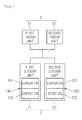
- an air conditioner includes: a plurality of indoor units; and a plurality of outdoor units connected to the plurality of indoor units, each of the plurality of outdoor units including a plurality of outdoor heat exchangers, wherein each of the outdoor heat exchangers includes a plurality of heat exchanger parts, and when a defrosting operation condition is satisfied during a heating operation, the plurality of heat exchanger parts constituting the plurality of outdoor heat exchangers successively perform a defrosting operation.
- Fig. 1 is a schematic view of an air conditioner according to an embodiment.
- Fig. 2 is a view illustrating a refrigerant cycle of the air conditioner of Fig. 1 .
- Fig. 3 is a flowchart for explaining a process of controlling an air conditioner according to an embodiment.
- Figs. 4 to 7 are schematic views for explaining an order of heat exchanger parts in which defrosting operations are performed in each of outdoor units.
- Figs. 8 and 9 are views illustrating a refrigerant flow when a specific outdoor heat exchanger performs a defrosting operation.
- Fig. 1 is a schematic view of an air conditioner according to an embodiment.
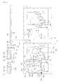
- Fig. 2 is a view illustrating a refrigerant cycle of the air conditioner of Fig. 1 .
- Fig. 2 illustrates a refrigerant flow when an air conditioner is operated in a heating mode.
- an air conditioner may include an outdoor unit 1 and an indoor unit 2 connected to the outdoor unit 1 through a refrigerant pipe.
- the outdoor unit 1 may include a plurality of outdoor units 11 and 12.
- the indoor unit 2 may include a plurality of indoor units 21 and 22.
- the present disclosure is not limited to the number of indoor unit and outdoor unit. That is, two or more outdoor units may be connected to two or more indoor units.
- the outdoor unit 1 includes a first outdoor unit 11 and a second outdoor unit 12. Since the first outdoor unit 11 and the second outdoor unit 12 have the same constitution, only the first outdoor unit 11 will be described below.
- first outdoor unit 11 may be equally applied to those of the second outdoor unit 12.
- reference numerals used for explaining the constitutions of the first outdoor unit 11 may be equally applied to those of the second outdoor unit 12 except for reference numerals necessary for explaining the present disclosure.
- Each of the outdoor units 11 and 12 includes a compression unit 110 for compressing a refrigerant and outdoor heat exchangers 130 and 200 in which outdoor air is heat-exchanged with the refrigerant.
- the first outdoor unit 11 includes the first outdoor heat exchanger 130
- the second outdoor unit 12 includes the second outdoor heat exchanger 200.
- the compression unit 110 may include one or more compressors.
- the compression unit 110 including a plurality of compressors 111 and 112 will be described as an example.
- a portion of the plurality of compressors 111 and 112 may be an inverter compressor 111 having variable capacity, and the other portion may be a constant-speed compressor 112.
- all of the compressors 111 and 112 may be the constant-speed compressors or the inverter compressors.
- the plurality of compressors 111 and 112 may be disposed in parallel.
- a portion of the plurality of compressors 111 and 112 or the whole compressors 111 and 112 may be operated according to the capacity of the indoor unit 2.
- a discharge side pipe of each of the compressors 111 and 112 includes an individual pipe 115 and a joint pipe 116. That is, the individual pipe 115 of each of the compressors 111 and 112 is jointed to the joint pipe 116.
- Oil separators 113 and 114 for separating oil from the refrigerant may be disposed on the individual pipe 115. The oil separated by the oil separators 113 and 114 may return to each of the compressors 111 and 112.
- the joint pipe 116 is connected to a four-way valve 120 for switching a passage of the refrigerant.
- the four-way valve 120 is connected to the outdoor heat exchanger 130 through a connection pipe unit.
- the connection pipe unit includes a common connection pipe 122, a first connection pipe 123, and a second connection pipe 124. Also, the four-way valve 120 may be connected to the accumulator 135, and the accumulator 135 may be connected to the compression unit 110.
- Each of the outdoor heat exchangers 130 and 200 includes first heat exchanger parts 131 and 201 and second heat exchanger parts 132 and 202.
- the first and second heat exchanger parts 131, 201, 132, and 202 may be independent heat exchangers separated from each other or a heat exchanger divided into two parts based on a refrigerant flow in a single outdoor heat exchanger.
- the first and second heat exchanger parts 131, 201, 132, and 202 may be horizontally or vertically disposed with respect to each other.
- the first and second heat exchanger parts 131, 201, 132, and 202 may have the same thermal capacity or thermal capacities different from each other.
- the first connection pipe 123 is connected to the first heat exchanger parts 131 and 201, and the second connection pipe 124 is connected to the second heat exchanger parts 132 and 202.
- the first and second connection pipes 123 and 124 may be a portion of the refrigerant pipe constituting each of the heat exchanger parts 131, 201, 132, and 202.
- a check valve 125 for allowing the refrigerant to flow in one direction is disposed in the second connection pipe 124.
- the refrigerant within the second heat exchanger parts 132 and 202 may flows only toward the common connection pipe 122 by the check valve 125.
- the refrigerant within the outdoor heat exchangers 130 and 200 may be heat-exchanged with outdoor air blowing by a fan motor assembly 140 (including an outdoor fan and a fan motor).
- the fan motor assembly may be provided in one or plurality.
- Fig. 2 illustrates one fan motor assembly.
- Each of the outdoor units 11 and 12 may further include an outdoor expansion mechanism 150.
- the outdoor expansion mechanism 150 does not expand a refrigerant when the refrigerant passing through the outdoor heat exchangers 130 and 200 pass, but expands a refrigerant when the refrigerant which does not pass through the outdoor heat exchangers 130 and 200 pass.
- the outdoor expansion mechanism 150 includes a first outdoor expansion valve 151 connected to the first heat exchanger parts 131 and 201 through a third connection pipe 154 and a second outdoor expansion valve 152 connected to the second heat exchanger parts 132 and 202 through a fourth connection pipe 155.
- the check valve 153 and the second outdoor expansion valve 152 may be disposed in parallel. That is, a parallel pipe parallelly disposed with respect to the fourth connection pipe 155 is provided.
- the check valve 153 is disposed in the parallel pipe. Only the refrigerant passing through the second heat exchanger parts 132 and 202 may flow through the check valve 153.
- each of the outdoor expansion valves 151 and 152 may be an electronic expansion valve (EEV).
- a pass-variable pipe 126 is connected to the third connection pipe 154 and the second connection pipe 124. Also, a pass-variable valve 127 is disposed in the pass-variable pipe 126.
- the pass-variable valve 127 may be a solenoid valve.
- the refrigerant may flow into the first heat exchanger parts 131 and 201 and the second heat exchanger parts 132 and 202 at the same time (i.e., the refrigerant is distributed into each of the heat exchanger parts to flow in parallel) or flow into the other heat exchanger part after flowing into one heat exchanger part or flow into only one heat exchanger part.
- a refrigerant having states different from each other for example, a temperature, pressure, gaseous, and liquid state
- the refrigerant may flow into the first heat exchanger parts 131 and 201 and the second heat exchanger parts 132 and 202 at the same time.
- the refrigerant may flow first into the first heat exchanger parts 131 and 201 and then flow into the second heat exchanger parts 132 and 202 via the pass-variable pipe 126.
- a bypass pipe unit is connected to the third connection pipe 154 and the fourth connection pipe 155.
- the bypass pipe unit is connected to the joint pipe 116.
- the bypass pipe unit may include a common pipe 160 and first and second bypass pipes 161 and 162 branched from the common pipe 160.
- the first bypass pipe 161 is connected to the third connection pipe 154, and the second bypass pipe 152 is connected to the fourth connection pipe 155.
- a first bypass valve 163 is disposed in the first bypass pipe 161, and a second bypass valve 164 is disposed in the second bypass pipe 162.
- each of the bypass valves 163 and 164 may be a solenoid valve through which a flow rate is adjustable.
- the bypass valves 163 and 164 may serve as decompressor, respectively.
- the bypass pipe unit may include a first bypass pipe connecting the joint pipe 116 to the third connection pipe 154 and a second bypass pipe connecting to the joint pipe 116 to the fourth connection pipe 115. That is, the common pipe may be omitted in the bypass pipe unit.
- bypass valves 163 and 164 When the bypass valves 163 and 164 are opened, a high-temperature refrigerant compressed by the compression unit 110 may be flow into the bypass pipes 161 and 162.
- the outdoor unit 1 may be connected to the indoor unit 2 through gas pipe units 31, 32, and 33 and liquid pipe units 34, 35, and 36.
- the gas pipe units may include an outdoor gas pipe 31, a common gas pipe 32, and an indoor gas pipe 33.
- the outdoor gas pipe 31 may be connected to the four-way valve 120 of each of the outdoor units 11 and 12.
- the indoor gas pipe 33 may be connected to the indoor heat exchangers 211 and 221 of each of the indoor units 21 and 22.
- the common gas pipe 32 connects the plurality of outdoor gas pipes 31 to the plurality of indoor gas pipes 33.
- the liquid pipe unit may include an indoor liquid pipe 34, a common liquid pipe 35, and an indoor liquid pipe 36.
- the outdoor liquid pipe 34 may be connected to the outdoor expansion mechanism 150.
- the indoor liquid pipe 36 is connected to the indoor expansion mechanism 213 and 223 of each of the indoor units 21 and 22.
- the common liquid pipe 35 connects the plurality of outdoor liquid pipes 34 to the plurality of indoor liquid pipes 36.
- Each of the indoor units 21 and 22 may include indoor heat exchangers 211 and 221, indoor fans 212 and 222, and indoor expansion mechanisms 213 and 223.
- each of the indoor expansion mechanisms 213 and 223 may be an EEV.
- a high-temperature high-pressure refrigerant compressed by the compression unit 110 flows into each of the indoor units 21 and 22 along the gas pipe units 31, 32, and 33 by switching the refrigerant passage through the four-way valve 120.
- the refrigerant flowing into each of the indoor units 21 and 22 is condensed in the indoor heat exchangers 211 and 221 and then passes through the indoor expansion mechanisms 213 and 223 without being expanded. Then, the refrigerant flows into each of the outdoor units 11 and 12 through the liquid pipe uni ts 34, 35, and 36.
- the refrigerant flowing into the outdoor units 11 and 12 is expanded by each of the outdoor expansion valves 151 and 152 and then flows into the outdoor heat exchangers 130 and 200.
- each of the bypass valves 163 and 164 is maintained in a closed state.
- the refrigerant is evaporated while passing through the outdoor heat exchangers 130 and 200, and then flows into the accumulator 135 via the four-way valves 120.
- a gaseous refrigerant of the refrigerant introduced into the accumulator 135 is introduced into the compression u nit 110.
- frosts may occur on the outdoor heat exchangers 130 and 200.
- a defrosting operation for removing the frosts from the outdoor heat exchangers 130 and 200 is required.
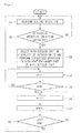
- Fig. 3 is a flowchart for explaining a process of controlling an air conditioner according to an embodiment.
- Figs. 4 to 7 are schematic views for explaining an order of heat exchanger parts in which defrosting operations are performed in each of outdoor units.
- Figs. 8 and 9 are views illustrating a refrigerant flow when a specific outdoor heat exchanger performs a defrosting operation.
- Fig. 8 illustrates a refrigerant flow when the first heat exchanger part of the first outdoor unit performs the defrosting operation
- Fig. 9 illustrates a refrigerant flow when the second heat exchanger part of the first outdoor unit performs the defrosting operation.
- the air conditioner performs a heating operation by a heating operation command.
- the outdoor heat exchangers 130 and 200 of each of the outdoor units serve as evaporators
- the indoor heat exchangers 211 and 221 of each of the indoor units serve as condensers.
- a control unit determines whether defrosting operation conditions are satisfied during the heating operation of the air conditioner.
- whether the defrosting operation conditions are satisfied may be determined by comparing an outlet pipe temperature of the outdoor heat exchanger to an outdoor temperature.
- time points at which the defrosting operation conditions are satisfied may be similar to each other in the plurality of outdoor units.
- the time point at which the defrosting operation conditions are satisfied may be different from each other in the outdoor units.
- the defrosting operation conditions may be satisfied in the whole outdoor units or in a reference number of outdoor units.
- whether the defrosting operation conditions are satisfied may be determined through various methods except for the above-described method. That is, the present disclosure is not limited to a method for determining whether the defrosting operation conditions are satisfied.
- the air conditioner is operated in a defrosting operation mode. Specifically, a specific outdoor unit of the plurality of outdoor units is selected, and a specific heat exchanger part of the selected outdoor unit is selected. That is, in operation S3, an n-th outdoor unit of the plurality of outdoor units is selected, and an m-th heat exchanger part of the selected n-th outdoor unit is selected to perform the defrosting operation.
- the first outdoor unit 11 is selected first, and then the second outdoor unit 12 is selected. Also, in each of the first and second outdoor units 11 and 12, the first heat exchanger part 131 or 210 is selected first, and then the second heat exchanger part 132 or 202 is selected.
- an order of the outdoor units and heat exchanger parts which perform the defrosting operation may be previously decided and stored in a memory (not shown).
- the outdoor unit in which the defrosting operation conditions are satisfied may be selected first in operation S3, and then other outdoor units may be selected according to a successive or specific order. That is, the order of the outdoor units and the heat exchanger parts which perform the deforesting operation may be decided whenever the defrosting operation conditions are satisfied.
- the master outdoor unit may be selected first, and then the sleeve outdoor unit may be selected.
- the heat exchanger part having a relatively small capacity may perform the defrosting operation first.
- the present disclosure is not limited to the selection of the outdoor for performing the defrosting operation and the selection order of the heat exchangers in the selected outdoor unit.
- the first bypass valve 163 is opened, and the second bypass valve 164 is closed (or is maintained in a closed state). Also, the first outdoor expansion valve 151 is closed.
- the refrigerant discharged from the compressor unit 110 flows along the first bypass pipe 161 and then flows into the first heat exchanger part 131 through the third connection pipe 154.
- the high-temperature refrigerant flowing into the first heat exchanger part 131 melts frosts on the first heat exchanger part 131 while flowing the first heat exchanger part 131 to remove the frosts on the first heat exchanger part 131.
- the condensed refrigerant discharged from the indoor unit 2 is expanded while flowing into the second outdoor expansion valve 152 and then heat-exchanged by the second heat exchanger part 132.
- the refrigerant passing through the first heat exchanger part 131 and the refrigerant passing through the second heat exchanger part 132 are mixed in the common connection pipe 122 to pass through the four-way valve 120.
- an m+1-th heat exchanger part performs the defrosting operation after the m-th heat exchanger part of the n-th outdoor unit completely performs the defrosting operation.
- the second heat exchanger part 132 may perform the defrosting operation as shown in Fig. 5 .
- the first bypass valve 163 is closed, and the second bypass valve 164 is opened.
- the first outdoor expansion valve 151 is opened, and the second outdoor expansion valve 152 is closed.
- a portion of the high-temperature refrigerant discharged from the compression unit 110 flows along the second bypass pipe 162 and then flows into the second heat exchanger part 32 through the fourth connection pipe 155.
- the high-temperature refrigerant flowing into the second heat exchanger part 132 melts frosts on the second heat exchanger part 132 while flowing into the second heat exchanger part 132 to remove the frosts on the second heat exchanger part 132.
- the total number of the heat exchanger parts of the n-th outdoor unit may be defined as an M number.
- an n+1-th outdoor unit is selected in operation S6, and then an m-th heat exchanger part of an n+1-th outdoor unit is selected to perform the defrosting operation.
- an m+1-th heat exchanger part performs the defrosting operation after the m-th heat exchanger part completely performs the defrosting operation.
- the first heat exchanger part of the second outdoor unit performs the defrosting operation first as shown in Fig. 6
- the second heat exchanger part of the second outdoor unit performs the defrosting operation as shown in Fig. 7 .
- the total number of the outdoor units may be defined as an N number.
- the plurality of heat exchanger parts of the specific outdoor unit successively perform the defrosting operation, and then the plurality of heat exchanger parts of the outdoor unit successively perform the defrosting operation.
- the indoor space may be continuously heated to maintain a comfort indoor space.
- the specific outdoor unit since the specific outdoor unit does not perform the defrosting operation, but a portion of the heat exchanger parts of the whole heat exchanger parts constituting the specific outdoor unit performs the defrosting operation and then the next heat exchanger part performs the defrosting operation, it may prevent the heating performance from being deteriorated. That is, since the capacity of the heat exchanger part acting as the evaporator is minimally reduced, the indoor temperature may be minimally reduced.
- the present disclosure is not limited thereto.
- one of the plurality of heat exchanger parts of the specific outdoor unit performs the defrosting operation and then one of the plurality of heat exchanger parts of the other outdoor unit may perform the defrosting operation. That is, even though the defrosting operation of the whole heat exchanger parts of the specific outdoor unit is not completely finished, one of the heat exchanger parts of the other outdoor unit may perform the defrosting operation.
- the plurality of heat exchanger parts constituting the whole outdoor unit may be decided in order for performing the defrosting operation to allow the plurality of heat exchanger parts to successively perform the defrosting operation.
- the defrosting operation order of the plurality of heat exchanger parts may be previously decided or changed whenever the defrosting operation conditions are satisfied.
- the outdoor heat exchanger is divided into the plurality of heat exchanger parts in the current embodiment, a portion of the specific outdoor heat exchanger may perform the defrosting operation and then the other portion may perform the defrosting operation, and also a portion of the specific outdoor heat exchanger may perform the defrosting operation and then a portion of the other outdoor heat exchanger may perform the defrosting operation even if the structure in which the outdoor heat exchanger is divided into the plurality of heat exchanger parts is not described.
Abstract
Description
- The present disclosure relates to an air conditioner.
- In general, air conditioners are apparatuses for cooling/heating an indoor space or purifying air using a refrigerant cycle including a compressor, condenser, an expansion mechanism, and an evaporator.
- Air conditioners are classified into air conditioner in which a single indoor unit is connected to a single outdoor unit and multi-type air conditioners in which a plurality of indoor units are connected to one or more outdoor units to provide the effect of a plurality of air conditioners.
- In case of the multi-type air conditioner according to the related art, when a heating operation is continuously performed, frosts may occur on an outdoor heat exchanger. Thus, a defrosting process is performed. When the defrosting process is performed, one outdoor unit of a plurality of outdoor units performs a cooling operation. Here, the defrosting process is performed on an outdoor heat exchanger of the outdoor unit in which the cooling operation is performed. However, in case of the multi-type air conditioner, since the rest outdoor units except for the outdoor unit in which the cooling operation is performed performs a heating operation, heating efficiency may be deteriorated and also a heating temperature may be reduced.
- The present invention provides an air conditioner according to
claim 1. Preferred embodiments are defined in the dependent claims. - In one embodiment, an air conditioner includes: a plurality of indoor units; and a plurality of outdoor units connected to the plurality of indoor units, each of the plurality of outdoor units including a plurality of outdoor heat exchangers, wherein each of the outdoor heat exchangers includes a plurality of heat exchanger parts, and when a defrosting operation condition is satisfied during a heating operation, the plurality of heat exchanger parts constituting the plurality of outdoor heat exchangers successively perform a defrosting operation.
- The details of one or more embodiments are set forth in the accompanying drawings and the description below. Other features will be apparent from the description and drawings, and from the claims.
-
Fig. 1 is a schematic view of an air conditioner according to an embodiment. -
Fig. 2 is a view illustrating a refrigerant cycle of the air conditioner ofFig. 1 . -
Fig. 3 is a flowchart for explaining a process of controlling an air conditioner according to an embodiment. -
Figs. 4 to 7 are schematic views for explaining an order of heat exchanger parts in which defrosting operations are performed in each of outdoor units. -
Figs. 8 and9 are views illustrating a refrigerant flow when a specific outdoor heat exchanger performs a defrosting operation. - Hereinafter, exemplary embodiments of the present disclosure will be described with reference to the accompanying drawings. Regarding the reference numerals assigned to the elements in the drawings, it should be noted that the same elements will be designated by the same reference numerals, wherever possible, even though they are shown in different drawings. Also, in the description of embodiments, detailed description of well-known related structures or functions will be omitted when it is deemed that such description will cause ambiguous interpretation of the present disclosure.
- Also, in the description of embodiments, terms such as first, second, A, B, (a), (b) or the like may be used herein when describing components of the present invention. Each of these terminologies is not used to define an essence, order or sequence of a corresponding component but used merely to distinguish the corresponding component from other component(s). It should be noted that if it is described in the specification that one component is "connected," "coupled" or "joined" to another component, the former may be directly "connected," "coupled," and "joined" to the latter or "connected", "coupled", and "jointed" to the latter via another component.
-
Fig. 1 is a schematic view of an air conditioner according to an embodiment.Fig. 2 is a view illustrating a refrigerant cycle of the air conditioner ofFig. 1 . For example,Fig. 2 illustrates a refrigerant flow when an air conditioner is operated in a heating mode. - Referring to
Figs. 1 and2 , an air conditioner according to an embodiment may include anoutdoor unit 1 and anindoor unit 2 connected to theoutdoor unit 1 through a refrigerant pipe. - The
outdoor unit 1 may include a plurality ofoutdoor units indoor unit 2 may include a plurality ofindoor units - The
outdoor unit 1 includes a firstoutdoor unit 11 and a secondoutdoor unit 12. Since the firstoutdoor unit 11 and the secondoutdoor unit 12 have the same constitution, only the firstoutdoor unit 11 will be described below. - The descriptions with respect to the first
outdoor unit 11 may be equally applied to those of the secondoutdoor unit 12. Also, reference numerals used for explaining the constitutions of the firstoutdoor unit 11 may be equally applied to those of the secondoutdoor unit 12 except for reference numerals necessary for explaining the present disclosure. - Each of the
outdoor units compression unit 110 for compressing a refrigerant andoutdoor heat exchangers outdoor unit 11 includes the firstoutdoor heat exchanger 130, and the secondoutdoor unit 12 includes the secondoutdoor heat exchanger 200. - The
compression unit 110 may include one or more compressors. In the current embodiment, thecompression unit 110 including a plurality ofcompressors compressors inverter compressor 111 having variable capacity, and the other portion may be a constant-speed compressor 112. Alternatively, all of thecompressors compressors compressors whole compressors indoor unit 2. - A discharge side pipe of each of the
compressors individual pipe 115 and ajoint pipe 116. That is, theindividual pipe 115 of each of thecompressors joint pipe 116.Oil separators individual pipe 115. The oil separated by theoil separators compressors - The
joint pipe 116 is connected to a four-way valve 120 for switching a passage of the refrigerant. The four-way valve 120 is connected to theoutdoor heat exchanger 130 through a connection pipe unit. The connection pipe unit includes acommon connection pipe 122, afirst connection pipe 123, and asecond connection pipe 124. Also, the four-way valve 120 may be connected to theaccumulator 135, and theaccumulator 135 may be connected to thecompression unit 110. - Each of the
outdoor heat exchangers heat exchanger parts heat exchanger parts heat exchanger parts heat exchanger parts heat exchanger parts - The
first connection pipe 123 is connected to the firstheat exchanger parts second connection pipe 124 is connected to the secondheat exchanger parts second connection pipes heat exchanger parts - Also, a
check valve 125 for allowing the refrigerant to flow in one direction is disposed in thesecond connection pipe 124. The refrigerant within the secondheat exchanger parts common connection pipe 122 by thecheck valve 125. - The refrigerant within the
outdoor heat exchangers Fig. 2 illustrates one fan motor assembly. - Each of the
outdoor units outdoor expansion mechanism 150. Theoutdoor expansion mechanism 150 does not expand a refrigerant when the refrigerant passing through theoutdoor heat exchangers outdoor heat exchangers - The
outdoor expansion mechanism 150 includes a firstoutdoor expansion valve 151 connected to the firstheat exchanger parts third connection pipe 154 and a secondoutdoor expansion valve 152 connected to the secondheat exchanger parts fourth connection pipe 155. Thecheck valve 153 and the secondoutdoor expansion valve 152 may be disposed in parallel. That is, a parallel pipe parallelly disposed with respect to thefourth connection pipe 155 is provided. Thecheck valve 153 is disposed in the parallel pipe. Only the refrigerant passing through the secondheat exchanger parts check valve 153. - The refrigerant expanded by the first
outdoor expansion valve 151 may flow Into the firstheat exchanger parts outdoor expansion valve 152 may flow into the secondheat exchanger parts outdoor expansion valves - A pass-
variable pipe 126 is connected to thethird connection pipe 154 and thesecond connection pipe 124. Also, a pass-variable valve 127 is disposed in the pass-variable pipe 126. For example, the pass-variable valve 127 may be a solenoid valve. - The refrigerant may flow into the first
heat exchanger parts heat exchanger parts heat exchanger parts - For example, when the air conditioner performs a heating operation, the refrigerant may flow into the first
heat exchanger parts heat exchanger parts heat exchanger parts heat exchanger parts variable pipe 126. - A bypass pipe unit is connected to the
third connection pipe 154 and thefourth connection pipe 155. The bypass pipe unit is connected to thejoint pipe 116. The bypass pipe unit may include a common pipe 160 and first andsecond bypass pipes first bypass pipe 161 is connected to thethird connection pipe 154, and thesecond bypass pipe 152 is connected to thefourth connection pipe 155. Also, afirst bypass valve 163 is disposed in thefirst bypass pipe 161, and asecond bypass valve 164 is disposed in thesecond bypass pipe 162. For example, each of thebypass valves bypass valves - For another example, the bypass pipe unit may include a first bypass pipe connecting the
joint pipe 116 to thethird connection pipe 154 and a second bypass pipe connecting to thejoint pipe 116 to thefourth connection pipe 115. That is, the common pipe may be omitted in the bypass pipe unit. - When the
bypass valves compression unit 110 may be flow into thebypass pipes - The
outdoor unit 1 may be connected to theindoor unit 2 throughgas pipe units liquid pipe units - The gas pipe units may include an
outdoor gas pipe 31, acommon gas pipe 32, and anindoor gas pipe 33. Theoutdoor gas pipe 31 may be connected to the four-way valve 120 of each of theoutdoor units indoor gas pipe 33 may be connected to theindoor heat exchangers indoor units common gas pipe 32 connects the plurality ofoutdoor gas pipes 31 to the plurality ofindoor gas pipes 33. - The liquid pipe unit may include an
indoor liquid pipe 34, acommon liquid pipe 35, and anindoor liquid pipe 36. Theoutdoor liquid pipe 34 may be connected to theoutdoor expansion mechanism 150. Theindoor liquid pipe 36 is connected to theindoor expansion mechanism indoor units common liquid pipe 35 connects the plurality of outdoorliquid pipes 34 to the plurality ofindoor liquid pipes 36. - Each of the
indoor units indoor heat exchangers indoor fans indoor expansion mechanisms indoor expansion mechanisms - Hereinafter, an operation of the air conditioner will be described. Since main concern is the defrosting operation of the outdoor exchanger when the air conditioner performs the heating operation, a refrigerant flow when the air conditioner performs the heating operation will be described below.
- Referring to
Fig. 2 , when the air conditioner performs the heating operation, a high-temperature high-pressure refrigerant compressed by thecompression unit 110 flows into each of theindoor units gas pipe units indoor units indoor heat exchangers indoor expansion mechanisms outdoor units pipe uni ts outdoor units outdoor expansion valves outdoor heat exchangers bypass valves - Then, the refrigerant is evaporated while passing through the
outdoor heat exchangers accumulator 135 via the four-way valves 120. A gaseous refrigerant of the refrigerant introduced into theaccumulator 135 is introduced into thecompression u nit 110. - As described above, when the heating operation is continuously performed, frosts may occur on the
outdoor heat exchangers outdoor heat exchangers -
Fig. 3 is a flowchart for explaining a process of controlling an air conditioner according to an embodiment.Figs. 4 to 7 are schematic views for explaining an order of heat exchanger parts in which defrosting operations are performed in each of outdoor units.Figs. 8 and9 are views illustrating a refrigerant flow when a specific outdoor heat exchanger performs a defrosting operation.Fig. 8 illustrates a refrigerant flow when the first heat exchanger part of the first outdoor unit performs the defrosting operation, andFig. 9 illustrates a refrigerant flow when the second heat exchanger part of the first outdoor unit performs the defrosting operation. - Referring to
Figs. 3 to 9 , in operation S1, the air conditioner performs a heating operation by a heating operation command. When the air conditioner performs the heating operation, theoutdoor heat exchangers indoor heat exchangers - In operation S2, a control unit determines whether defrosting operation conditions are satisfied during the heating operation of the air conditioner.
- In the current embodiment., for example, whether the defrosting operation conditions are satisfied may be determined by comparing an outlet pipe temperature of the outdoor heat exchanger to an outdoor temperature. Here, since the plurality of outdoor units are operated at the same time, time points at which the defrosting operation conditions are satisfied may be similar to each other in the plurality of outdoor units. However, the time point at which the defrosting operation conditions are satisfied may be different from each other in the outdoor units. In case where the defrosting operation conditions are satisfied in the air conditioner, the defrosting operation conditions may be satisfied in the whole outdoor units or in a reference number of outdoor units.
- In the current embodiment, whether the defrosting operation conditions are satisfied may be determined through various methods except for the above-described method. That is, the present disclosure is not limited to a method for determining whether the defrosting operation conditions are satisfied.
- In the result determined in the operation S2, when the defrosting operation conditions are satisfied, the air conditioner is operated in a defrosting operation mode. Specifically, a specific outdoor unit of the plurality of outdoor units is selected, and a specific heat exchanger part of the selected outdoor unit is selected. That is, in operation S3, an n-th outdoor unit of the plurality of outdoor units is selected, and an m-th heat exchanger part of the selected n-th outdoor unit is selected to perform the defrosting operation.
- In the current embodiment, for example, the first
outdoor unit 11 is selected first, and then the secondoutdoor unit 12 is selected. Also, in each of the first and secondoutdoor units heat exchanger part 131 or 210 is selected first, and then the secondheat exchanger part - Although the specific outdoor unit and the specific heat exchanger part are selected in the operation S3, an order of the outdoor units and heat exchanger parts which perform the defrosting operation may be previously decided and stored in a memory (not shown). Alternatively, the outdoor unit in which the defrosting operation conditions are satisfied may be selected first in operation S3, and then other outdoor units may be selected according to a successive or specific order. That is, the order of the outdoor units and the heat exchanger parts which perform the deforesting operation may be decided whenever the defrosting operation conditions are satisfied.
- For another example, in case where a master outdoor unit and a outdoor unit are disposed between the plurality of outdoor units, the master outdoor unit may be selected first, and then the sleeve outdoor unit may be selected.
- For another example, in case where the heat exchanger parts of the specific outdoor unit have capacities different from each other, the heat exchanger part having a relatively small capacity may perform the defrosting operation first. The present disclosure is not limited to the selection of the outdoor for performing the defrosting operation and the selection order of the heat exchangers in the selected outdoor unit.
- When the m-th heat exchanger part (e.g., the first heat exchanger part of the first outdoor heat exchanger) performs the defrosting operation, the
first bypass valve 163 is opened, and thesecond bypass valve 164 is closed (or is maintained in a closed state). Also, the firstoutdoor expansion valve 151 is closed. - When the air conditioner performs the defrosting operation, since a refrigerant flow within the indoor unit is equal to that within the indoor unit during the heating operation, only a refrigerant flow within the outdoor unit will be described below. Also, a refrigerant flow within the outdoor uni t (unselected outdoor unit in the operation S2) in which the defrosting operation is not performed in the plurality of outdoor units is equal to that within the outdoor unit during the heating operation. Thus, only a refrigerant flow within the outdoor unit in which the defrosting operation is performed will be described below.
- A portion of a high-temperature refrigerant compressed by the
compressor unit 110 of the firstoutdoor unit 11 flows into the indoor unit along thegas pipe units first bypass valve 163 is opened, the refrigerant discharged from thecompressor unit 110 flows along thefirst bypass pipe 161 and then flows into the firstheat exchanger part 131 through thethird connection pipe 154. The high-temperature refrigerant flowing into the firstheat exchanger part 131 melts frosts on the firstheat exchanger part 131 while flowing the firstheat exchanger part 131 to remove the frosts on the firstheat exchanger part 131. On the other hand, the condensed refrigerant discharged from theindoor unit 2 is expanded while flowing into the secondoutdoor expansion valve 152 and then heat-exchanged by the secondheat exchanger part 132. The refrigerant passing through the firstheat exchanger part 131 and the refrigerant passing through the secondheat exchanger part 132 are mixed in thecommon connection pipe 122 to pass through the four-way valve 120. - In operation S4, an m+1-th heat exchanger part performs the defrosting operation after the m-th heat exchanger part of the n-th outdoor unit completely performs the defrosting operation. For example, after the first
heat exchanger part 131 of the firstoutdoor unit 11 completely performs the defrosting operation, the secondheat exchanger part 132 may perform the defrosting operation as shown inFig. 5 . As a result, thefirst bypass valve 163 is closed, and thesecond bypass valve 164 is opened. Then, the firstoutdoor expansion valve 151 is opened, and the secondoutdoor expansion valve 152 is closed. - Then, a portion of the high-temperature refrigerant discharged from the
compression unit 110 flows along thesecond bypass pipe 162 and then flows into the secondheat exchanger part 32 through thefourth connection pipe 155. The high-temperature refrigerant flowing into the secondheat exchanger part 132 melts frosts on the secondheat exchanger part 132 while flowing into the secondheat exchanger part 132 to remove the frosts on the secondheat exchanger part 132. - In operation S5, it is determined whether the whole heat exchanger parts of the n-th outdoor unit completely perform the defrosting operation after the selected m+1-th heat exchanger part completely performs the defrosting operation. In the current embodiment, the total number of the heat exchanger parts of the n-th outdoor unit may be defined as an M number.
- If it is determined that the whole heat exchanger parts of the n-th outdoor unit completely perform the defrosting operation, an n+1-th outdoor unit is selected in operation S6, and then an m-th heat exchanger part of an n+1-th outdoor unit is selected to perform the defrosting operation. In operation S7, an m+1-th heat exchanger part performs the defrosting operation after the m-th heat exchanger part completely performs the defrosting operation. For example, the first heat exchanger part of the second outdoor unit performs the defrosting operation first as shown in
Fig. 6 , and then the second heat exchanger part of the second outdoor unit performs the defrosting operation as shown inFig. 7 . - In operation S8, it is determined whether the heat exchanger parts of the whole outdoor units completely perform the defrosting operation during the successive defrosting operation of the heat exchanger parts. In the current embodiment, the total number of the outdoor units may be defined as an N number.
- If it is determined that the whole outdoor unit completely perform the defrosting operation, the process return to the operation S1 Thus, the air conditioner performs the heating operation.
- In summary, in the current embodiment, the plurality of heat exchanger parts of the specific outdoor unit successively perform the defrosting operation, and then the plurality of heat exchanger parts of the outdoor unit successively perform the defrosting operation.
- According to the embodiment, since the indoor unit performs the heating operation during the defrosting operation of the air conditioner, the indoor space may be continuously heated to maintain a comfort indoor space.
- Also, since the specific outdoor unit does not perform the defrosting operation, but a portion of the heat exchanger parts of the whole heat exchanger parts constituting the specific outdoor unit performs the defrosting operation and then the next heat exchanger part performs the defrosting operation, it may prevent the heating performance from being deteriorated. That is, since the capacity of the heat exchanger part acting as the evaporator is minimally reduced, the indoor temperature may be minimally reduced.
- In the current embodiment, although the plurality of heat exchanger parts of the specific outdoor unit completely perform the defrosting operation and then the plurality of heat exchanger parts of the next outdoor unit successively perform the defrosting operation, the present disclosure is not limited thereto. For example, one of the plurality of heat exchanger parts of the specific outdoor unit performs the defrosting operation and then one of the plurality of heat exchanger parts of the other outdoor unit may perform the defrosting operation. That is, even though the defrosting operation of the whole heat exchanger parts of the specific outdoor unit is not completely finished, one of the heat exchanger parts of the other outdoor unit may perform the defrosting operation. Thus, the plurality of heat exchanger parts constituting the whole outdoor unit may be decided in order for performing the defrosting operation to allow the plurality of heat exchanger parts to successively perform the defrosting operation. Here, the defrosting operation order of the plurality of heat exchanger parts may be previously decided or changed whenever the defrosting operation conditions are satisfied.
- Also, although the outdoor heat exchanger is divided into the plurality of heat exchanger parts in the current embodiment, a portion of the specific outdoor heat exchanger may perform the defrosting operation and then the other portion may perform the defrosting operation, and also a portion of the specific outdoor heat exchanger may perform the defrosting operation and then a portion of the other outdoor heat exchanger may perform the defrosting operation even if the structure in which the outdoor heat exchanger is divided into the plurality of heat exchanger parts is not described.
- Even though all the elements of the embodiments are coupled into one or operated in the combined state, the present disclosure is not limited to such an embodiment. That is, all the elements may be selectively combined with each other without departing the scope of the invention. Furthermore, when it is described that one comprises (or includes or has) some elements, it should be understood that it may comprise (or include or has) only those elements, or it may comprise (or include or have) other element as well as those elements if there is no specific limitation. Unless otherwise specifically defined herein, all terms including technical or scientific terms are to be given meanings understood by those skilled in the art. Like terms defined in dictionaries, generally used terms needs to be construed as meaning used in technical contexts and are not construed as ideal or excessively formal meanings unless otherwise clearly defined herein.
- Although embodiments have been described with reference to a number of illustrative embodiments thereof, it will be understood by those skilled in the art that various changes in form and details may be made therein without departing from the scope of the invention as defined by the appended claims. Therefore, the preferred embodiments should be considered in descriptive sense only and not for purposes of limitation, and also the technical scope of the invention is not limited to the embodiments. Furthermore, is defined not by the detailed description of the invention but by the appended claims, and all differences within the scope will be construed as being comprised in the present disclosure.
Claims (9)
- An air conditioner comprising:a plurality of indoor units; anda plurality of outdoor units connected to the plurality of indoor units, each of the plurality of outdoor units comprising a plurality of outdoor heat exchangers,wherein each of the outdoor heat exchangers comprises a plurality of heat exchanger parts, andwhen a defrosting operation condition is satisfied during a heating operation, the plurality of heat exchanger parts constituting the plurality of outdoor heat exchangers are configured to successively perform a defrosting operation.
- The air conditioner according to claim 1, wherein the plurality of heat exchanger parts of one outdoor unit of the plurality of outdoor units are configured to successively perform the defrosting operation, and when the one outdoor unit completely performs the defrosting operation, the plurality of heat exchanger parts of the next outdoor unit are configured to successively perform the defrosting operation.
- The air conditioner according to claim 1, wherein, before the whole heat exchanger parts of one outdoor unit of the plurality of outdoor units completely perform the defrosting operation, one heat exchanger part of the plurality of heat exchanger part of the other outdoor unit is configured to perform the defrosting operation.
- The air conditioner according to claim 1, wherein, after a specific heat exchanger part completely performs the defrosting operation, the next heat exchanger part is configured to perform the defrosting operation.
- The air conditioner according to claim 1, wherein the air conditioner is configured so that an order of the plurality of outdoor units performing the defrosting operation and an order of the plurality of heat exchanger parts of a specific outdoor unit are previously decided and stored in a memory.
- The air conditioner according to claim 1, wherein the air conditioner is configured so that an order of the plurality of outdoor units performing the defrosting operation and an order of the plurality of heat exchanger parts of a specific outdoor unit are decided when the defrosting operation condition is satisfied.
- The air conditioner according to any of claims 1 to 6, wherein each of the outdoor units comprises:a compression unit compressing one or more compressors;a four-way valve for switching a flow direction of a refrigerant discharged from the compression unit;a plurality of bypass pipes for bypassing the refrigerant discharged from the compression unit into each of the plurality of heat exchanger parts; anda plurality of bypass valves disposed in the plurality of bypass pipes, respectively.
- The air conditioner according to claim 7, wherein each of the outdoor units further comprises a plurality of outdoor expansion valves for expanding the refrigerant during the heating operation,
when a specific heat exchanger part performs the defrosting operation, the outdoor expansion valve corresponding to the specific heat exchanger part is closed, and
the bypass valve corresponding to the specific heat exchanger part is opened. - A method of operating an air conditioner preferably according to any of claims 1 to 8.
Applications Claiming Priority (1)
| Application Number | Priority Date | Filing Date | Title |
|---|---|---|---|
| KR1020110110389A KR101319687B1 (en) | 2011-10-27 | 2011-10-27 | Multi type air conditioner and method of controlling the same |
Publications (3)
| Publication Number | Publication Date |
|---|---|
| EP2589896A2 true EP2589896A2 (en) | 2013-05-08 |
| EP2589896A3 EP2589896A3 (en) | 2014-01-08 |
| EP2589896B1 EP2589896B1 (en) | 2020-02-12 |
Family
ID=45936934
Family Applications (1)
| Application Number | Title | Priority Date | Filing Date |
|---|---|---|---|
| EP12161518.1A Active EP2589896B1 (en) | 2011-10-27 | 2012-03-27 | Air Conditioner |
Country Status (3)
| Country | Link |
|---|---|
| US (1) | US9791193B2 (en) |
| EP (1) | EP2589896B1 (en) |
| KR (1) | KR101319687B1 (en) |
Cited By (9)
| Publication number | Priority date | Publication date | Assignee | Title |
|---|---|---|---|---|
| CN103953998A (en) * | 2014-01-25 | 2014-07-30 | 宁波奥克斯电气有限公司 | Processing method for compressor faults of some outdoor units of multi-coupled air conditioner during heating process |
| CN105091436A (en) * | 2015-08-26 | 2015-11-25 | 珠海格力电器股份有限公司 | Air conditioner unit and heating and defrosting method thereof |
| CN106152644A (en) * | 2016-06-30 | 2016-11-23 | 珠海格力电器股份有限公司 | Heat pump air conditioner unit defrosting control method and system |
| EP3006866A4 (en) * | 2013-05-31 | 2017-01-04 | Mitsubishi Electric Corporation | Air conditioner |
| CN106969428A (en) * | 2017-05-09 | 2017-07-21 | 广东美的暖通设备有限公司 | Multi-connected air conditioner device |
| EP3273188A1 (en) * | 2016-07-20 | 2018-01-24 | Mitsubishi Heavy Industries Thermal Systems, Ltd. | Control device, air conditioner, and controlling method |
| CN107709900A (en) * | 2015-07-06 | 2018-02-16 | 三菱电机株式会社 | Refrigerating circulatory device |
| EP3473946A4 (en) * | 2016-12-28 | 2019-06-26 | Mitsubishi Heavy Industries Thermal Systems, Ltd. | Multi-split air conditioner control device, multi-split air conditioner, multi-split air conditioner control method, and multi-split air conditioner control program |
| CN113531776A (en) * | 2021-07-26 | 2021-10-22 | 珠海格力电器股份有限公司 | Defrosting control method and device for air conditioning unit, storage medium and air conditioning unit |
Families Citing this family (15)
| Publication number | Priority date | Publication date | Assignee | Title |
|---|---|---|---|---|
| US9625184B2 (en) * | 2013-01-31 | 2017-04-18 | Trane International Inc. | Multi-split HVAC system |
| KR102344058B1 (en) * | 2013-12-24 | 2021-12-28 | 엘지전자 주식회사 | An air conditioning system and a method for controlling the same |
| KR102163743B1 (en) * | 2013-12-24 | 2020-10-12 | 엘지전자 주식회사 | An air conditioning system and a method for controlling the same |
| JP6249932B2 (en) * | 2014-12-04 | 2017-12-20 | 三菱電機株式会社 | Air conditioning system |
| KR101685846B1 (en) * | 2015-09-30 | 2016-12-20 | 엘지전자 주식회사 | An air conditioner |
| JP6252606B2 (en) * | 2016-01-15 | 2017-12-27 | ダイキン工業株式会社 | Refrigeration equipment |
| KR102015031B1 (en) * | 2016-01-28 | 2019-10-21 | 엘지전자 주식회사 | Air conditioner |
| KR101720495B1 (en) | 2016-03-15 | 2017-04-10 | 엘지전자 주식회사 | Air conditioner |
| WO2017217383A1 (en) * | 2016-06-14 | 2017-12-21 | 東芝キヤリア株式会社 | Refrigeration cycle device |
| EP3324137B1 (en) * | 2016-11-18 | 2022-01-05 | LG Electronics Inc. | Air conditioner and control method thereof |
| CN106766333B (en) * | 2017-01-03 | 2023-08-22 | 珠海格力电器股份有限公司 | Low-temperature jet enthalpy-increasing air conditioning system |
| JP6842961B2 (en) * | 2017-03-17 | 2021-03-17 | 大阪瓦斯株式会社 | Hybrid heat pump system |
| US11015851B2 (en) * | 2017-07-07 | 2021-05-25 | Mitsubishi Electric Corporation | Refrigeration cycle device |
| JP6965462B2 (en) * | 2018-12-11 | 2021-11-10 | 三菱電機株式会社 | Air conditioner |
| CN114353398B (en) * | 2021-12-02 | 2023-04-14 | 珠海格力电器股份有限公司 | Air conditioner for controlling flow path to defrost condenser and defrosting method |
Family Cites Families (18)
| Publication number | Priority date | Publication date | Assignee | Title |
|---|---|---|---|---|
| US4151722A (en) * | 1975-08-04 | 1979-05-01 | Emhart Industries, Inc. | Automatic defrost control for refrigeration systems |
| US4122686A (en) * | 1977-06-03 | 1978-10-31 | Gulf & Western Manufacturing Company | Method and apparatus for defrosting a refrigeration system |
| GB2168137B (en) * | 1984-12-11 | 1988-12-14 | Sanden Corp | Refrigerated display cabinet |
| JPH07111288B2 (en) * | 1985-09-20 | 1995-11-29 | 株式会社日立製作所 | Air conditioner |
| JPS62255762A (en) * | 1986-04-30 | 1987-11-07 | 株式会社日立製作所 | Air conditioner |
| AU636726B2 (en) * | 1990-03-19 | 1993-05-06 | Mitsubishi Denki Kabushiki Kaisha | Air conditioning system |
| JP2839343B2 (en) * | 1990-08-10 | 1998-12-16 | 株式会社日立製作所 | Multi air conditioner |
| JPH07234038A (en) * | 1994-02-18 | 1995-09-05 | Sanyo Electric Co Ltd | Multiroom type cooling-heating equipment and operating method thereof |
| JP3888403B2 (en) * | 1997-12-18 | 2007-03-07 | 株式会社富士通ゼネラル | Method and apparatus for controlling air conditioner |
| JP2002188873A (en) | 2000-12-20 | 2002-07-05 | Fujitsu General Ltd | Refrigerating equipment of air conditioner |
| US6629422B2 (en) * | 2001-06-07 | 2003-10-07 | Keith E. Wellman | Sequential defrosting of refrigerated display cases |
| KR100463548B1 (en) * | 2003-01-13 | 2004-12-29 | 엘지전자 주식회사 | Air conditioner |
| KR100504509B1 (en) * | 2003-01-16 | 2005-08-03 | 엘지전자 주식회사 | Multi-type air conditioner for cooling/heating the same time |
| US7171817B2 (en) * | 2004-12-30 | 2007-02-06 | Birgen Daniel J | Heat exchanger liquid refrigerant defrost system |
| JP4114691B2 (en) * | 2005-12-16 | 2008-07-09 | ダイキン工業株式会社 | Air conditioner |
| KR100820821B1 (en) | 2006-12-26 | 2008-04-11 | 엘지전자 주식회사 | Air conditioning system |
| JP4990221B2 (en) | 2008-05-26 | 2012-08-01 | 日立アプライアンス株式会社 | Air conditioner |
| KR20100081621A (en) * | 2009-01-06 | 2010-07-15 | 엘지전자 주식회사 | Air conditioner and defrosting driving method of the same |
-
2011
- 2011-10-27 KR KR1020110110389A patent/KR101319687B1/en active IP Right Grant
-
2012
- 2012-03-27 EP EP12161518.1A patent/EP2589896B1/en active Active
- 2012-03-29 US US13/433,473 patent/US9791193B2/en active Active
Non-Patent Citations (1)
| Title |
|---|
| None |
Cited By (13)
| Publication number | Priority date | Publication date | Assignee | Title |
|---|---|---|---|---|
| EP3006866A4 (en) * | 2013-05-31 | 2017-01-04 | Mitsubishi Electric Corporation | Air conditioner |
| CN103953998A (en) * | 2014-01-25 | 2014-07-30 | 宁波奥克斯电气有限公司 | Processing method for compressor faults of some outdoor units of multi-coupled air conditioner during heating process |
| CN107709900A (en) * | 2015-07-06 | 2018-02-16 | 三菱电机株式会社 | Refrigerating circulatory device |
| EP3321606A4 (en) * | 2015-07-06 | 2019-02-27 | Mitsubishi Electric Corporation | Refrigeration cycle device |
| CN107709900B (en) * | 2015-07-06 | 2020-04-24 | 三菱电机株式会社 | Refrigeration cycle device |
| CN105091436A (en) * | 2015-08-26 | 2015-11-25 | 珠海格力电器股份有限公司 | Air conditioner unit and heating and defrosting method thereof |
| CN106152644A (en) * | 2016-06-30 | 2016-11-23 | 珠海格力电器股份有限公司 | Heat pump air conditioner unit defrosting control method and system |
| CN106152644B (en) * | 2016-06-30 | 2018-09-11 | 珠海格力电器股份有限公司 | Heat pump air conditioner unit defrosting control method and system |
| EP3273188A1 (en) * | 2016-07-20 | 2018-01-24 | Mitsubishi Heavy Industries Thermal Systems, Ltd. | Control device, air conditioner, and controlling method |
| EP3473946A4 (en) * | 2016-12-28 | 2019-06-26 | Mitsubishi Heavy Industries Thermal Systems, Ltd. | Multi-split air conditioner control device, multi-split air conditioner, multi-split air conditioner control method, and multi-split air conditioner control program |
| CN106969428A (en) * | 2017-05-09 | 2017-07-21 | 广东美的暖通设备有限公司 | Multi-connected air conditioner device |
| CN113531776A (en) * | 2021-07-26 | 2021-10-22 | 珠海格力电器股份有限公司 | Defrosting control method and device for air conditioning unit, storage medium and air conditioning unit |
| CN113531776B (en) * | 2021-07-26 | 2022-05-10 | 珠海格力电器股份有限公司 | Defrosting control method and device for air conditioning unit, storage medium and air conditioning unit |
Also Published As
| Publication number | Publication date |
|---|---|
| KR101319687B1 (en) | 2013-10-17 |
| EP2589896A3 (en) | 2014-01-08 |
| US20130104576A1 (en) | 2013-05-02 |
| EP2589896B1 (en) | 2020-02-12 |
| KR20130046058A (en) | 2013-05-07 |
| US9791193B2 (en) | 2017-10-17 |
Similar Documents
| Publication | Publication Date | Title |
|---|---|---|
| EP2589896B1 (en) | Air Conditioner | |
| EP2515053B1 (en) | Multi type air conditioner and operating method | |
| EP2557377B1 (en) | Air conditioning and hot-water supply composite system | |
| EP2889554B1 (en) | Air conditioning system | |
| KR102373851B1 (en) | Air conditioner | |
| EP2128535A1 (en) | Air conditioner | |
| EP3062031A1 (en) | Air conditioner | |
| EP2218984B1 (en) | Air conditioner and method of controlling the same | |
| EP3751211B1 (en) | Air conditioner | |
| EP1672298A2 (en) | Air conditioner | |
| EP3159630B1 (en) | Air conditioner | |
| EP2587177A2 (en) | Air conditioner | |
| EP1669695A2 (en) | Air conditioner | |
| EP3144606B1 (en) | Air conditioner | |
| EP2568232A2 (en) | Air conditioner | |
| EP2587189A2 (en) | Air conditioner | |
| EP2587192B1 (en) | Air conditioner | |
| JP3984250B2 (en) | Multi-room air conditioner | |
| EP3954948A1 (en) | Multi-type air conditioner | |
| KR101877986B1 (en) | Air conditioner | |
| KR102136874B1 (en) | Air conditioner | |
| KR20220027563A (en) | Multi-air conditioner for heating and cooling operations |
Legal Events
| Date | Code | Title | Description |
|---|---|---|---|
| PUAI | Public reference made under article 153(3) epc to a published international application that has entered the european phase |
Free format text: ORIGINAL CODE: 0009012 |
|
| 17P | Request for examination filed |
Effective date: 20120327 |
|
| AK | Designated contracting states |
Kind code of ref document: A2 Designated state(s): AL AT BE BG CH CY CZ DE DK EE ES FI FR GB GR HR HU IE IS IT LI LT LU LV MC MK MT NL NO PL PT RO RS SE SI SK SM TR |
|
| AX | Request for extension of the european patent |
Extension state: BA ME |
|
| PUAL | Search report despatched |
Free format text: ORIGINAL CODE: 0009013 |
|
| AK | Designated contracting states |
Kind code of ref document: A3 Designated state(s): AL AT BE BG CH CY CZ DE DK EE ES FI FR GB GR HR HU IE IS IT LI LT LU LV MC MK MT NL NO PL PT RO RS SE SI SK SM TR |
|
| AX | Request for extension of the european patent |
Extension state: BA ME |
|
| RIC1 | Information provided on ipc code assigned before grant |
Ipc: F25B 13/00 20060101AFI20131202BHEP Ipc: F25B 47/02 20060101ALI20131202BHEP |
|
| RBV | Designated contracting states (corrected) |
Designated state(s): AL AT BE BG CH CY CZ DE DK EE ES FI FR GB GR HR HU IE IS IT LI LT LU LV MC MK MT NL NO PL PT RO RS SE SI SK SM TR |
|
| STAA | Information on the status of an ep patent application or granted ep patent |
Free format text: STATUS: EXAMINATION IS IN PROGRESS |
|
| 17Q | First examination report despatched |
Effective date: 20161125 |
|
| GRAP | Despatch of communication of intention to grant a patent |
Free format text: ORIGINAL CODE: EPIDOSNIGR1 |
|
| STAA | Information on the status of an ep patent application or granted ep patent |
Free format text: STATUS: GRANT OF PATENT IS INTENDED |
|
| INTG | Intention to grant announced |
Effective date: 20190828 |
|
| GRAS | Grant fee paid |
Free format text: ORIGINAL CODE: EPIDOSNIGR3 |
|
| GRAA | (expected) grant |
Free format text: ORIGINAL CODE: 0009210 |
|
| STAA | Information on the status of an ep patent application or granted ep patent |
Free format text: STATUS: THE PATENT HAS BEEN GRANTED |
|
| AK | Designated contracting states |
Kind code of ref document: B1 Designated state(s): AL AT BE BG CH CY CZ DE DK EE ES FI FR GB GR HR HU IE IS IT LI LT LU LV MC MK MT NL NO PL PT RO RS SE SI SK SM TR |
|
| REG | Reference to a national code |
Ref country code: GB Ref legal event code: FG4D |
|
| REG | Reference to a national code |
Ref country code: CH Ref legal event code: EP |
|
| REG | Reference to a national code |
Ref country code: AT Ref legal event code: REF Ref document number: 1232648 Country of ref document: AT Kind code of ref document: T Effective date: 20200215 |
|
| REG | Reference to a national code |
Ref country code: DE Ref legal event code: R096 Ref document number: 602012067641 Country of ref document: DE |
|
| REG | Reference to a national code |
Ref country code: IE Ref legal event code: FG4D |
|
| PG25 | Lapsed in a contracting state [announced via postgrant information from national office to epo] |
Ref country code: FI Free format text: LAPSE BECAUSE OF FAILURE TO SUBMIT A TRANSLATION OF THE DESCRIPTION OR TO PAY THE FEE WITHIN THE PRESCRIBED TIME-LIMIT Effective date: 20200212 Ref country code: NO Free format text: LAPSE BECAUSE OF FAILURE TO SUBMIT A TRANSLATION OF THE DESCRIPTION OR TO PAY THE FEE WITHIN THE PRESCRIBED TIME-LIMIT Effective date: 20200512 Ref country code: RS Free format text: LAPSE BECAUSE OF FAILURE TO SUBMIT A TRANSLATION OF THE DESCRIPTION OR TO PAY THE FEE WITHIN THE PRESCRIBED TIME-LIMIT Effective date: 20200212 |
|
| REG | Reference to a national code |
Ref country code: LT Ref legal event code: MG4D |
|
| REG | Reference to a national code |
Ref country code: NL Ref legal event code: MP Effective date: 20200212 |
|
| PG25 | Lapsed in a contracting state [announced via postgrant information from national office to epo] |
Ref country code: GR Free format text: LAPSE BECAUSE OF FAILURE TO SUBMIT A TRANSLATION OF THE DESCRIPTION OR TO PAY THE FEE WITHIN THE PRESCRIBED TIME-LIMIT Effective date: 20200513 Ref country code: IS Free format text: LAPSE BECAUSE OF FAILURE TO SUBMIT A TRANSLATION OF THE DESCRIPTION OR TO PAY THE FEE WITHIN THE PRESCRIBED TIME-LIMIT Effective date: 20200612 Ref country code: SE Free format text: LAPSE BECAUSE OF FAILURE TO SUBMIT A TRANSLATION OF THE DESCRIPTION OR TO PAY THE FEE WITHIN THE PRESCRIBED TIME-LIMIT Effective date: 20200212 Ref country code: LV Free format text: LAPSE BECAUSE OF FAILURE TO SUBMIT A TRANSLATION OF THE DESCRIPTION OR TO PAY THE FEE WITHIN THE PRESCRIBED TIME-LIMIT Effective date: 20200212 Ref country code: HR Free format text: LAPSE BECAUSE OF FAILURE TO SUBMIT A TRANSLATION OF THE DESCRIPTION OR TO PAY THE FEE WITHIN THE PRESCRIBED TIME-LIMIT Effective date: 20200212 Ref country code: BG Free format text: LAPSE BECAUSE OF FAILURE TO SUBMIT A TRANSLATION OF THE DESCRIPTION OR TO PAY THE FEE WITHIN THE PRESCRIBED TIME-LIMIT Effective date: 20200512 |
|
| PG25 | Lapsed in a contracting state [announced via postgrant information from national office to epo] |
Ref country code: NL Free format text: LAPSE BECAUSE OF FAILURE TO SUBMIT A TRANSLATION OF THE DESCRIPTION OR TO PAY THE FEE WITHIN THE PRESCRIBED TIME-LIMIT Effective date: 20200212 |
|
| PG25 | Lapsed in a contracting state [announced via postgrant information from national office to epo] |
Ref country code: RO Free format text: LAPSE BECAUSE OF FAILURE TO SUBMIT A TRANSLATION OF THE DESCRIPTION OR TO PAY THE FEE WITHIN THE PRESCRIBED TIME-LIMIT Effective date: 20200212 Ref country code: PT Free format text: LAPSE BECAUSE OF FAILURE TO SUBMIT A TRANSLATION OF THE DESCRIPTION OR TO PAY THE FEE WITHIN THE PRESCRIBED TIME-LIMIT Effective date: 20200705 Ref country code: LT Free format text: LAPSE BECAUSE OF FAILURE TO SUBMIT A TRANSLATION OF THE DESCRIPTION OR TO PAY THE FEE WITHIN THE PRESCRIBED TIME-LIMIT Effective date: 20200212 Ref country code: ES Free format text: LAPSE BECAUSE OF FAILURE TO SUBMIT A TRANSLATION OF THE DESCRIPTION OR TO PAY THE FEE WITHIN THE PRESCRIBED TIME-LIMIT Effective date: 20200212 Ref country code: CZ Free format text: LAPSE BECAUSE OF FAILURE TO SUBMIT A TRANSLATION OF THE DESCRIPTION OR TO PAY THE FEE WITHIN THE PRESCRIBED TIME-LIMIT Effective date: 20200212 Ref country code: SM Free format text: LAPSE BECAUSE OF FAILURE TO SUBMIT A TRANSLATION OF THE DESCRIPTION OR TO PAY THE FEE WITHIN THE PRESCRIBED TIME-LIMIT Effective date: 20200212 Ref country code: EE Free format text: LAPSE BECAUSE OF FAILURE TO SUBMIT A TRANSLATION OF THE DESCRIPTION OR TO PAY THE FEE WITHIN THE PRESCRIBED TIME-LIMIT Effective date: 20200212 Ref country code: DK Free format text: LAPSE BECAUSE OF FAILURE TO SUBMIT A TRANSLATION OF THE DESCRIPTION OR TO PAY THE FEE WITHIN THE PRESCRIBED TIME-LIMIT Effective date: 20200212 Ref country code: SK Free format text: LAPSE BECAUSE OF FAILURE TO SUBMIT A TRANSLATION OF THE DESCRIPTION OR TO PAY THE FEE WITHIN THE PRESCRIBED TIME-LIMIT Effective date: 20200212 |
|
| REG | Reference to a national code |
Ref country code: CH Ref legal event code: PL |
|
| REG | Reference to a national code |
Ref country code: DE Ref legal event code: R097 Ref document number: 602012067641 Country of ref document: DE |
|
| REG | Reference to a national code |
Ref country code: AT Ref legal event code: MK05 Ref document number: 1232648 Country of ref document: AT Kind code of ref document: T Effective date: 20200212 |
|
| PG25 | Lapsed in a contracting state [announced via postgrant information from national office to epo] |
Ref country code: MC Free format text: LAPSE BECAUSE OF FAILURE TO SUBMIT A TRANSLATION OF THE DESCRIPTION OR TO PAY THE FEE WITHIN THE PRESCRIBED TIME-LIMIT Effective date: 20200212 |
|
| PLBE | No opposition filed within time limit |
Free format text: ORIGINAL CODE: 0009261 |
|
| STAA | Information on the status of an ep patent application or granted ep patent |
Free format text: STATUS: NO OPPOSITION FILED WITHIN TIME LIMIT |
|
| REG | Reference to a national code |
Ref country code: BE Ref legal event code: MM Effective date: 20200331 |
|
| PG25 | Lapsed in a contracting state [announced via postgrant information from national office to epo] |
Ref country code: LU Free format text: LAPSE BECAUSE OF NON-PAYMENT OF DUE FEES Effective date: 20200327 |
|
| 26N | No opposition filed |
Effective date: 20201113 |
|
| PG25 | Lapsed in a contracting state [announced via postgrant information from national office to epo] |
Ref country code: LI Free format text: LAPSE BECAUSE OF NON-PAYMENT OF DUE FEES Effective date: 20200331 Ref country code: FR Free format text: LAPSE BECAUSE OF NON-PAYMENT OF DUE FEES Effective date: 20200412 Ref country code: CH Free format text: LAPSE BECAUSE OF NON-PAYMENT OF DUE FEES Effective date: 20200331 Ref country code: IE Free format text: LAPSE BECAUSE OF NON-PAYMENT OF DUE FEES Effective date: 20200327 Ref country code: AT Free format text: LAPSE BECAUSE OF FAILURE TO SUBMIT A TRANSLATION OF THE DESCRIPTION OR TO PAY THE FEE WITHIN THE PRESCRIBED TIME-LIMIT Effective date: 20200212 Ref country code: IT Free format text: LAPSE BECAUSE OF FAILURE TO SUBMIT A TRANSLATION OF THE DESCRIPTION OR TO PAY THE FEE WITHIN THE PRESCRIBED TIME-LIMIT Effective date: 20200212 |
|
| PG25 | Lapsed in a contracting state [announced via postgrant information from national office to epo] |
Ref country code: BE Free format text: LAPSE BECAUSE OF NON-PAYMENT OF DUE FEES Effective date: 20200331 Ref country code: PL Free format text: LAPSE BECAUSE OF FAILURE TO SUBMIT A TRANSLATION OF THE DESCRIPTION OR TO PAY THE FEE WITHIN THE PRESCRIBED TIME-LIMIT Effective date: 20200212 Ref country code: SI Free format text: LAPSE BECAUSE OF FAILURE TO SUBMIT A TRANSLATION OF THE DESCRIPTION OR TO PAY THE FEE WITHIN THE PRESCRIBED TIME-LIMIT Effective date: 20200212 |
|
| GBPC | Gb: european patent ceased through non-payment of renewal fee |
Effective date: 20200512 |
|
| PG25 | Lapsed in a contracting state [announced via postgrant information from national office to epo] |
Ref country code: GB Free format text: LAPSE BECAUSE OF NON-PAYMENT OF DUE FEES Effective date: 20200512 |
|
| PG25 | Lapsed in a contracting state [announced via postgrant information from national office to epo] |
Ref country code: TR Free format text: LAPSE BECAUSE OF FAILURE TO SUBMIT A TRANSLATION OF THE DESCRIPTION OR TO PAY THE FEE WITHIN THE PRESCRIBED TIME-LIMIT Effective date: 20200212 Ref country code: MT Free format text: LAPSE BECAUSE OF FAILURE TO SUBMIT A TRANSLATION OF THE DESCRIPTION OR TO PAY THE FEE WITHIN THE PRESCRIBED TIME-LIMIT Effective date: 20200212 Ref country code: CY Free format text: LAPSE BECAUSE OF FAILURE TO SUBMIT A TRANSLATION OF THE DESCRIPTION OR TO PAY THE FEE WITHIN THE PRESCRIBED TIME-LIMIT Effective date: 20200212 |
|
| PG25 | Lapsed in a contracting state [announced via postgrant information from national office to epo] |
Ref country code: MK Free format text: LAPSE BECAUSE OF FAILURE TO SUBMIT A TRANSLATION OF THE DESCRIPTION OR TO PAY THE FEE WITHIN THE PRESCRIBED TIME-LIMIT Effective date: 20200212 Ref country code: AL Free format text: LAPSE BECAUSE OF FAILURE TO SUBMIT A TRANSLATION OF THE DESCRIPTION OR TO PAY THE FEE WITHIN THE PRESCRIBED TIME-LIMIT Effective date: 20200212 |
|
| PGFP | Annual fee paid to national office [announced via postgrant information from national office to epo] |
Ref country code: DE Payment date: 20230206 Year of fee payment: 12 |