EP2589874A1 - Reverse flow gas turbine combustor having a venturi for reducing wakes in cooling airflow - Google Patents
Reverse flow gas turbine combustor having a venturi for reducing wakes in cooling airflow Download PDFInfo
- Publication number
- EP2589874A1 EP2589874A1 EP12190923.8A EP12190923A EP2589874A1 EP 2589874 A1 EP2589874 A1 EP 2589874A1 EP 12190923 A EP12190923 A EP 12190923A EP 2589874 A1 EP2589874 A1 EP 2589874A1
- Authority
- EP
- European Patent Office
- Prior art keywords
- flow
- air
- combustion system
- venturi
- obstructing element
- Prior art date
- Legal status (The legal status is an assumption and is not a legal conclusion. Google has not performed a legal analysis and makes no representation as to the accuracy of the status listed.)
- Granted
Links
Images


Classifications
-
- F—MECHANICAL ENGINEERING; LIGHTING; HEATING; WEAPONS; BLASTING
- F23—COMBUSTION APPARATUS; COMBUSTION PROCESSES
- F23R—GENERATING COMBUSTION PRODUCTS OF HIGH PRESSURE OR HIGH VELOCITY, e.g. GAS-TURBINE COMBUSTION CHAMBERS
- F23R3/00—Continuous combustion chambers using liquid or gaseous fuel
- F23R3/002—Wall structures
-
- F—MECHANICAL ENGINEERING; LIGHTING; HEATING; WEAPONS; BLASTING
- F23—COMBUSTION APPARATUS; COMBUSTION PROCESSES
- F23R—GENERATING COMBUSTION PRODUCTS OF HIGH PRESSURE OR HIGH VELOCITY, e.g. GAS-TURBINE COMBUSTION CHAMBERS
- F23R3/00—Continuous combustion chambers using liquid or gaseous fuel
- F23R3/42—Continuous combustion chambers using liquid or gaseous fuel characterised by the arrangement or form of the flame tubes or combustion chambers
- F23R3/54—Reverse-flow combustion chambers
-
- F—MECHANICAL ENGINEERING; LIGHTING; HEATING; WEAPONS; BLASTING
- F23—COMBUSTION APPARATUS; COMBUSTION PROCESSES
- F23R—GENERATING COMBUSTION PRODUCTS OF HIGH PRESSURE OR HIGH VELOCITY, e.g. GAS-TURBINE COMBUSTION CHAMBERS
- F23R2900/00—Special features of, or arrangements for continuous combustion chambers; Combustion processes therefor
- F23R2900/03044—Impingement cooled combustion chamber walls or subassemblies
Definitions
- the subject matter disclosed herein relates to a combustion system, and more specifically to a combustion system with an air passage defined by a liner and a flow sleeve, and a venturi generally restricting and diffusing airflow in the air passage.
- Gas turbines include a compressor that supplies compressed air to a combustor. Specifically, compressed air is supplied through a gap or space between a liner and a flow sleeve of the combustor. There are typically different types of structures that may be disposed within the space between the liner and the flow sleeve such as, for example, a crossfire tube or a flame detector. Flow disturbances, which are typically referred to as wakes, may be created as the compressed air flows past these structures.
- a wake is a zone of aerodynamic disturbance created by a component such as a crossfire tube, and represents a region of re-circulating flow located downstream of the structure.
- the presence of wakes in the space between the liner and the flow sleeve may create several issues. For example, fuel injected downstream of the structure may be pulled into the wake. Fuel may accumulate in the wake and cause flame holding, which in turn decreases gas turbine performance. Wakes may also cause hardware issues in the gas turbine, which may potentially cause the gas turbine to shut down. Wakes may also create a higher pressure drop across the liner. In an effort to improve features such as gas turbine flame holding performance, a relatively wake free flow field is provided.
- a combustion system having a liner, a flow sleeve, a flow-obstructing element and a venturi.
- the liner is disposed around a combustion region.
- the flow sleeve is disposed around the liner.
- the liner and the flow sleeve cooperate to create an air passage having an airflow located between the liner and the flow sleeve.
- the flow-obstructing element is disposed within the air passage, and generally obstructs the airflow in the air passage to create wakes in the airflow.
- the venturi is disposed downstream from the flow-obstructing element, and generally restricts and diffuses the airflow in the air passage to generally reduce wakes in the airflow.
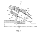
- FIG. 1 is an exemplary illustration of a combustion system 10 having a combustor body 20, a quaternary cap 22, an end cover 24, and at least one fuel nozzle 26.
- the fuel nozzle 26 is attached to the end cover 24, at a head end 28 of the combustion system 10.
- Air is compressed by a compressor 30 into a stream of compressor discharge air 32, which is provided to the combustion system 10.
- the compressor discharge air 32 is then mixed with fuel supplied by the fuel nozzle 26 of the combustion system 10.
- the combustor body 20 includes a combustion region 38 that is defined by a liner 40.
- the combustion system 10 also includes a flow sleeve 42 that is disposed around the liner 40.
- the combustion system 10 is employed in a gas turbine system (not shown).
- the liner 40 and the flow sleeve 42 cooperate together and create an air passage 44.
- the air passage 44 is created in the gap or space between the liner 40 and the flow sleeve 42.
- the air passage 44 has an airflow located between the liner 40 and the flow sleeve 42.
- a portion of the compressor discharge air 32 is provided to the air passage 44.
- the compressor discharge air 32 flows in the air passage 44 to the fuel nozzle 26, which distributes an air-fuel mixture into the combustion region 38.
- the compressor discharge air 32 located in the air passage 44 may be used for cooling and for entry into the head end 28.
- the compressor discharge air 32 is also provided to a second air passage 46 that is defined by a combustor housing 48 and a casing wall or outer surface 50 of the flow sleeve 42. Both the air passage 44 and the second air passage 46 deliver the compressor discharge air 32 to the quaternary cap 22.
- a flow-obstructing element 54 is disposed within the air passage 44.
- the flow-obstructing element 54 is typically any device that generally obstructs the airflow in the air passage 44. Specifically, the flow-obstructing element 54 obstructs the airflow to create a wake (not shown). The wake is typically a region of re-circulating flow downstream of the flow-obstructing element 54.
- the flow-obstructing element 54 may be any type of device usually found in the air passage 44 of a gas turbine, such as, for example, a cross-fire tube, a flame detector, a spark plug, a liner stop, a boss, a pressure probe, or a sensor.
- a venturi 60 is disposed downstream from the flow-obstructing element 54 and is defined as a portion of the flow sleeve 42.
- the venturi 60 is employed to generally restrict airflow in the air passage 44 and diffuse the airflow to a set of quaternary vanes 62 without a significant amount of airflow separation. That is, the venturi 60 is employed to substantially reduce the wakes created by the flow-obstructing element 54 before the airflow reaches the quaternary vanes 62.
- the venturi 60 has a converging section 66 and a diverging section 68.
- the converging section 66 is employed to restrict the airflow in the air passage 44, and the diverging section is employed to diffuse the airflow to the quaternary vanes 62.
- the venturi 60 also has a throat 70, which connects the converging section 66 with the diverging section 68.
- the throat 70 provides a reduction in the cross-sectional area of the air passage 44 ranging from about 20 to about 70 percent.
- the throat 70 is positioned at a specified distance from the flow-obstructing element 54.
- the flow-obstructing element 54 includes a generally rounded shape and has a diameter D.
- a flow-obstructing element 154 is generally rectangular in shape and includes a width W. Continuing to refer to FIG. 4 , the width W or the diameter D (shown in FIG.
- the throat 70 of the venturi 60 is positioned at a specific distance which is annotated by N*D, where D is the diameter D of the flow-obstructing element 54, and N is a number ranging from about 1 to about 10. That is, the specified distance N*D ranges from about the diameter D of the flow-obstructing element 54 to about ten times the diameter D of the flow-obstructing element 54.
- N*D the specified distance N*D ranges from about the diameter D of the flow-obstructing element 54 to about ten times the diameter D of the flow-obstructing element 54.
- a generally rectangular flow-obstructing element is employed (such as the flow-obstructing element 154 that is illustrated in FIG.
- the specific distance may be calculated by N*W, where W is the width of the flow-obstructing element 54. It is to be understood that while FIGS. 2 and 4 illustrate generally rounded or rectangular profiles, the flow-obstructing element 54 may include any type of shape or configuration.
- At least one air aperture 72 may also be provided in the venturi portion 60 of the flow sleeve 42 to fluidly connected to the air passage 46 to the air passage 44.
- the air aperture 72 is located within the flow sleeve 42 at the diverging section 68 of the venturi portion 60. It should be noted that while FIG. 2 illustrates the air aperture 72 located at the diverging section 68, it is to be understood that other locations may be used as well.
- the air aperture 72 may be located in the converging section 66 as well.
- the air aperture 72 may be located in the flow sleeve 42 upstream of the venturi 60, and downstream of the flow-obstructing element 54.
- the air aperture 72 may be used to introduce relatively higher pressure air into the air passage 44. Specifically, referring to both of FIGS. 1-2 , the air aperture 72 receives a portion of the compressor discharge air 32 from the second air passage 46. The airflow in the second air passage 46 has a higher pressure than the airflow located in the air passage 44. Thus, the air aperture 72 locally introduces a relatively higher pressure air into the airflow of the air passage 44.
- the air aperture 72 may be included in an effort to increase the air pressure in the air passage 44, because the air pressure across the venturi 60 decreases as the velocity of the airflow increases. The air aperture 72 adds air to the wake, which therefore increases the velocity of the air located within the wake. It should be noted that while the presence of the air aperture 72 is illustrated, it is to be understood that the air aperture 72 may be omitted in another embodiment as well.
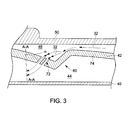
- FIG. 3 is a cross-sectional view of multiple air apertures 72 located within the flow sleeve 42.
- the air apertures 72 are typically thru-holes located within the diverging section 68 of the flow sleeve 42.
- the air apertures 72 may also be angled in relation to a vertical axis A-A, as shown by angle ⁇ . In one embodiment, the angle ⁇ ranges between about 5 degrees to about 80 degrees.
- the compressor discharge air 32 flows through the air apertures 72 and into the air passage 44.
- FIG. 2 illustrates the air aperture 72 having a generally circular configuration
- the air aperture 72 may include other configurations as well.
- the air apertures 72 may include a slotted or a teardrop configuration as well.
- FIGS. 4-5 are schematic illustrations that show several different arrangements of the air apertures 172 and 272.
- the air apertures 172 are arranged in a staggered configuration circumferentially along a diverging section 168. Similar to the embodiment as shown in FIG. 2 , each of the air apertures 172 are positioned downstream of a flow-obstructing element 154.
- the air apertures 272 include a generally rectangular profile.
- Some of the air apertures 272 are located adjacent to and generally surrounding a flow liner stop 254. A remaining portion of the air apertures 272 are positioned downstream of the flow liner stop 254. It should be noted that a portion of the air apertures 272 may also be positioned upstream of the flow liner stop 254 as well (not shown in FIG. 5 ).
- venturi 60 results in a relatively wake-free airflow in the air passage 44 that is delivered to the quaternary cap 22 and the quaternary vanes 62. Reduction in wakes within the air passage 44 tends to reduce or substantially prevent the occurrence of flame holding. A generally wake-free airflow in the air passage 44 may also improve features, such as gas turbine flame holding performance. Because the air pressure across the venturi 60 decreases as the velocity of the airflow increases, in one embodiment, the air aperture 72 is also included in an effort to increase the air pressure in the air passage 44.
Landscapes
- Engineering & Computer Science (AREA)
- Chemical & Material Sciences (AREA)
- Combustion & Propulsion (AREA)
- Mechanical Engineering (AREA)
- General Engineering & Computer Science (AREA)
- Structures Of Non-Positive Displacement Pumps (AREA)
- Turbine Rotor Nozzle Sealing (AREA)
Abstract
Description
- The subject matter disclosed herein relates to a combustion system, and more specifically to a combustion system with an air passage defined by a liner and a flow sleeve, and a venturi generally restricting and diffusing airflow in the air passage.
- Gas turbines include a compressor that supplies compressed air to a combustor. Specifically, compressed air is supplied through a gap or space between a liner and a flow sleeve of the combustor. There are typically different types of structures that may be disposed within the space between the liner and the flow sleeve such as, for example, a crossfire tube or a flame detector. Flow disturbances, which are typically referred to as wakes, may be created as the compressed air flows past these structures.
- A wake is a zone of aerodynamic disturbance created by a component such as a crossfire tube, and represents a region of re-circulating flow located downstream of the structure. The presence of wakes in the space between the liner and the flow sleeve may create several issues. For example, fuel injected downstream of the structure may be pulled into the wake. Fuel may accumulate in the wake and cause flame holding, which in turn decreases gas turbine performance. Wakes may also cause hardware issues in the gas turbine, which may potentially cause the gas turbine to shut down. Wakes may also create a higher pressure drop across the liner. In an effort to improve features such as gas turbine flame holding performance, a relatively wake free flow field is provided.
- According to one aspect of the invention, a combustion system is provided having a liner, a flow sleeve, a flow-obstructing element and a venturi. The liner is disposed around a combustion region. The flow sleeve is disposed around the liner. The liner and the flow sleeve cooperate to create an air passage having an airflow located between the liner and the flow sleeve. The flow-obstructing element is disposed within the air passage, and generally obstructs the airflow in the air passage to create wakes in the airflow. The venturi is disposed downstream from the flow-obstructing element, and generally restricts and diffuses the airflow in the air passage to generally reduce wakes in the airflow.
- These and other advantages and features will become more apparent from the following description taken in conjunction with the drawings.
- The subject matter, which is regarded as the invention, is particularly pointed out and distinctly claimed in the claims at the conclusion of the specification. The foregoing and other features, and advantages of the invention are apparent from the following detailed description taken in conjunction with the accompanying drawings in which:
-
FIG. 1 is a cross-sectional side view of a combustion system with features according to the teachings herein; -
FIG. 2 is a side perspective view of an airflow passage of the combustion system shown inFIG. 1 having a venturi and at least one air aperture therethrough; -
FIG. 3 is a cross-sectional view of an alternate airflow passage similar to that shown inFIG. 2 ; -
FIG. 4 is a schematic overhead view of an alternative embodiment of the air aperture shown inFIG. 2 ; and -
FIG. 5 is a schematic overhead view of another embodiment of the air aperture shown inFIG. 2 . - The detailed description explains embodiments of the invention, together with advantages and features, by way of example with reference to the drawings.
-
FIG. 1 is an exemplary illustration of acombustion system 10 having acombustor body 20, aquaternary cap 22, anend cover 24, and at least onefuel nozzle 26. Thefuel nozzle 26 is attached to theend cover 24, at ahead end 28 of thecombustion system 10. Air is compressed by acompressor 30 into a stream ofcompressor discharge air 32, which is provided to thecombustion system 10. Thecompressor discharge air 32 is then mixed with fuel supplied by thefuel nozzle 26 of thecombustion system 10. Thecombustor body 20 includes acombustion region 38 that is defined by aliner 40. Thecombustion system 10 also includes aflow sleeve 42 that is disposed around theliner 40. In one exemplary embodiment, thecombustion system 10 is employed in a gas turbine system (not shown). - In the embodiment as shown, the
liner 40 and theflow sleeve 42 cooperate together and create anair passage 44. Theair passage 44 is created in the gap or space between theliner 40 and theflow sleeve 42. Theair passage 44 has an airflow located between theliner 40 and theflow sleeve 42. Specifically, a portion of thecompressor discharge air 32 is provided to theair passage 44. Thecompressor discharge air 32 flows in theair passage 44 to thefuel nozzle 26, which distributes an air-fuel mixture into thecombustion region 38. Thecompressor discharge air 32 located in theair passage 44 may be used for cooling and for entry into thehead end 28. Thecompressor discharge air 32 is also provided to asecond air passage 46 that is defined by acombustor housing 48 and a casing wall orouter surface 50 of theflow sleeve 42. Both theair passage 44 and thesecond air passage 46 deliver thecompressor discharge air 32 to thequaternary cap 22. - Referring to both
FIGS. 1-2 , a flow-obstructingelement 54 is disposed within theair passage 44. The flow-obstructingelement 54 is typically any device that generally obstructs the airflow in theair passage 44. Specifically, the flow-obstructingelement 54 obstructs the airflow to create a wake (not shown). The wake is typically a region of re-circulating flow downstream of the flow-obstructingelement 54. The flow-obstructingelement 54 may be any type of device usually found in theair passage 44 of a gas turbine, such as, for example, a cross-fire tube, a flame detector, a spark plug, a liner stop, a boss, a pressure probe, or a sensor. - A
venturi 60 is disposed downstream from the flow-obstructingelement 54 and is defined as a portion of theflow sleeve 42. Referring now toFIG. 2 , theventuri 60 is employed to generally restrict airflow in theair passage 44 and diffuse the airflow to a set ofquaternary vanes 62 without a significant amount of airflow separation. That is, theventuri 60 is employed to substantially reduce the wakes created by the flow-obstructingelement 54 before the airflow reaches thequaternary vanes 62. Specifically, theventuri 60 has aconverging section 66 and a divergingsection 68. Theconverging section 66 is employed to restrict the airflow in theair passage 44, and the diverging section is employed to diffuse the airflow to thequaternary vanes 62. - The
venturi 60 also has athroat 70, which connects theconverging section 66 with the divergingsection 68. In one embodiment, thethroat 70 provides a reduction in the cross-sectional area of theair passage 44 ranging from about 20 to about 70 percent. In one embodiment, thethroat 70 is positioned at a specified distance from the flow-obstructingelement 54. Specifically, in the exemplary embodiment as illustrated, the flow-obstructingelement 54 includes a generally rounded shape and has a diameter D. Alternatively, in another embodiment as shown inFIG. 4 , a flow-obstructingelement 154 is generally rectangular in shape and includes a width W. Continuing to refer toFIG. 4 , the width W or the diameter D (shown inFIG. 2 ) is measured in relation to adiameter 180 of theflow sleeve 142. Referring back toFIG. 2 , thethroat 70 of theventuri 60 is positioned at a specific distance which is annotated by N*D, where D is the diameter D of the flow-obstructingelement 54, and N is a number ranging from about 1 to about 10. That is, the specified distance N*D ranges from about the diameter D of the flow-obstructingelement 54 to about ten times the diameter D of the flow-obstructingelement 54. In an alternative embodiment, if a generally rectangular flow-obstructing element is employed (such as the flow-obstructingelement 154 that is illustrated inFIG. 4 ), then the specific distance may be calculated by N*W, where W is the width of the flow-obstructingelement 54. It is to be understood that whileFIGS. 2 and4 illustrate generally rounded or rectangular profiles, the flow-obstructingelement 54 may include any type of shape or configuration. - Continuing to refer to
FIG. 2 , in one embodiment at least oneair aperture 72 may also be provided in theventuri portion 60 of theflow sleeve 42 to fluidly connected to theair passage 46 to theair passage 44. Specifically, theair aperture 72 is located within theflow sleeve 42 at the divergingsection 68 of theventuri portion 60. It should be noted that whileFIG. 2 illustrates theair aperture 72 located at the divergingsection 68, it is to be understood that other locations may be used as well. For example, theair aperture 72 may be located in the convergingsection 66 as well. In another embodiment, theair aperture 72 may be located in theflow sleeve 42 upstream of theventuri 60, and downstream of the flow-obstructingelement 54. Theair aperture 72 may be used to introduce relatively higher pressure air into theair passage 44. Specifically, referring to both ofFIGS. 1-2 , theair aperture 72 receives a portion of thecompressor discharge air 32 from thesecond air passage 46. The airflow in thesecond air passage 46 has a higher pressure than the airflow located in theair passage 44. Thus, theair aperture 72 locally introduces a relatively higher pressure air into the airflow of theair passage 44. Theair aperture 72 may be included in an effort to increase the air pressure in theair passage 44, because the air pressure across theventuri 60 decreases as the velocity of the airflow increases. Theair aperture 72 adds air to the wake, which therefore increases the velocity of the air located within the wake. It should be noted that while the presence of theair aperture 72 is illustrated, it is to be understood that theair aperture 72 may be omitted in another embodiment as well. - In the embodiment as shown in
FIG. 2 , theair aperture 72 is located within thewall 74 of theflow sleeve 42.FIG. 3 is a cross-sectional view ofmultiple air apertures 72 located within theflow sleeve 42. As shown inFIG. 3 , theair apertures 72 are typically thru-holes located within the divergingsection 68 of theflow sleeve 42. The air apertures 72 may also be angled in relation to a vertical axis A-A, as shown by angle α. In one embodiment, the angle α ranges between about 5 degrees to about 80 degrees. Thecompressor discharge air 32 flows through theair apertures 72 and into theair passage 44. - Although
FIG. 2 illustrates theair aperture 72 having a generally circular configuration, it is to be understood that theair aperture 72 may include other configurations as well. For example, in another embodiment, theair apertures 72 may include a slotted or a teardrop configuration as well.FIGS. 4-5 are schematic illustrations that show several different arrangements of theair apertures FIG. 4 , theair apertures 172 are arranged in a staggered configuration circumferentially along a divergingsection 168. Similar to the embodiment as shown inFIG. 2 , each of theair apertures 172 are positioned downstream of a flow-obstructingelement 154. In an alternative embodiment shown inFIG. 5 , theair apertures 272 include a generally rectangular profile. Some of theair apertures 272 are located adjacent to and generally surrounding aflow liner stop 254. A remaining portion of theair apertures 272 are positioned downstream of theflow liner stop 254. It should be noted that a portion of theair apertures 272 may also be positioned upstream of the flow liner stop 254 as well (not shown inFIG. 5 ). - Referring now to
FIGS. 1-5 , including theventuri 60 results in a relatively wake-free airflow in theair passage 44 that is delivered to thequaternary cap 22 and thequaternary vanes 62. Reduction in wakes within theair passage 44 tends to reduce or substantially prevent the occurrence of flame holding. A generally wake-free airflow in theair passage 44 may also improve features, such as gas turbine flame holding performance. Because the air pressure across theventuri 60 decreases as the velocity of the airflow increases, in one embodiment, theair aperture 72 is also included in an effort to increase the air pressure in theair passage 44. - While the invention has been described in detail in connection with only a limited number of embodiments, it should be readily understood that the invention is not limited to such disclosed embodiments. Rather, the invention can be modified to incorporate any number of variations, alterations, substitutions or equivalent arrangements not heretofore described, but which are commensurate with the spirit and scope of the invention. Additionally, while various embodiments of the invention have been described, it is to be understood that aspects of the invention may include only some of the described embodiments. Accordingly, the invention is not to be seen as limited by the foregoing description, but is only limited by the scope of the appended claims.
Claims (13)
- A combustion system, comprising:a liner (40) disposed around a combustion region (38);a flow sleeve (42) disposed around the liner (40), the liner and the flow sleeve cooperating to create an air passage (44) having an airflow located between the liner (40) and the flow sleeve (42);a flow-obstructing element (54) disposed within the air passage (44), the flow-obstructing element generally obstructing the airflow in the air passage and creating wakes in the airflow; anda venturi (60) disposed downstream from the flow-obstructing element, the venturi generally restricting and diffusing the airflow in the air passage (44) to generally reduce wakes in the airflow.
- The combustion system of claim 1, wherein the venturi (60) is defined by the flow sleeve (42).
- The combustion system of claim 1 or claim 2, wherein the venturi includes a converging section (66), a diverging section (68), and a throat (70), wherein the throat connects the converging section with the diverging section, and wherein the throat provides a reduction in a cross-sectional area of the air passage ranging from about 20 to about 70 percent.
- The combustion system of any preceding claim, wherein the flow-obstructing element (54) includes a dimension that represents one of a width and a diameter of the flow-obstructing element.
- The combustion system of claim 4, wherein the throat of the venturi (60) is located at a specified distance from the flow-obstructing element (54), wherein the specified distance ranges from about the dimension of the flow-obstructing element to about ten times the dimension of the flow-obstructing element.
- The combustion system of any preceding claim, comprising at least one air aperture (72) fluidly connected to the air passage, wherein the at least one air aperture receives a high pressure air that is injected into the air passage, the high pressure air having a pressure that is greater than an air passage pressure of the air passage.
- The combustion system of claim 6, wherein the at least one air aperture is located on one of converging section of the venturi, a diverging section of the venturi, and upstream of the venturi and downstream of the flow-obstructing element.
- The combustion system of claim 6, wherein the at least one air aperture is a thru-hole located within the flow sleeve, and wherein the at least one air aperture is positioned at an angle in relation to a vertical axis.
- The combustion system of claim 8, wherein the angle ranges between about 5 degrees to about 80 degrees.
- The combustion system of claim 6, comprising a plurality of air apertures, wherein a portion of the plurality of air apertures are positioned adjacent to and generally surrounding the flow-obstructing element, and another portion of the plurality of air apertures are positioned downstream of the flow-obstructing element, and a remaining portion of the air apertures are positioned upstream of the flow-obstructing element.
- The combustion system of any preceding claim, wherein the flow-obstructing element is one of a cross-fire tube, a flame detector, a spark plug, a liner stop, a boss, a pressure probe, and a sensor.
- The combustion system of any preceding claim, wherein the airflow is directed to a set of quaternary vanes located in the combustion system.
- A gas turbine having combustion system according to any preceding claim.
Applications Claiming Priority (1)
| Application Number | Priority Date | Filing Date | Title |
|---|---|---|---|
| US13/289,537 US9267687B2 (en) | 2011-11-04 | 2011-11-04 | Combustion system having a venturi for reducing wakes in an airflow |
Publications (2)
| Publication Number | Publication Date |
|---|---|
| EP2589874A1 true EP2589874A1 (en) | 2013-05-08 |
| EP2589874B1 EP2589874B1 (en) | 2019-09-18 |
Family
ID=47172447
Family Applications (1)
| Application Number | Title | Priority Date | Filing Date |
|---|---|---|---|
| EP12190923.8A Active EP2589874B1 (en) | 2011-11-04 | 2012-10-31 | Gas turbine combustion system having a venturi for reducing wakes in cooling airflow |
Country Status (3)
| Country | Link |
|---|---|
| US (1) | US9267687B2 (en) |
| EP (1) | EP2589874B1 (en) |
| CN (1) | CN103090411B (en) |
Families Citing this family (12)
| Publication number | Priority date | Publication date | Assignee | Title |
|---|---|---|---|---|
| US20130086920A1 (en) * | 2011-10-05 | 2013-04-11 | General Electric Company | Combustor and method for supplying flow to a combustor |
| US9182122B2 (en) * | 2011-10-05 | 2015-11-10 | General Electric Company | Combustor and method for supplying flow to a combustor |
| US9631815B2 (en) * | 2012-12-28 | 2017-04-25 | General Electric Company | System and method for a turbine combustor |
| FR3011620B1 (en) * | 2013-10-04 | 2018-03-09 | Snecma | TURBOMACHINE COMBUSTION CHAMBER WITH IMPROVED AIR INPUT PASSING DOWN A CANDLE PITCH ORIFICE |
| US10100730B2 (en) | 2015-03-11 | 2018-10-16 | Pratt & Whitney Canada Corp. | Secondary air system with venturi |
| EP3115693B1 (en) * | 2015-07-10 | 2021-09-01 | Ansaldo Energia Switzerland AG | Sequential combustor and method for operating the same |
| US10495311B2 (en) * | 2016-06-28 | 2019-12-03 | DOOSAN Heavy Industries Construction Co., LTD | Transition part assembly and combustor including the same |
| KR102377720B1 (en) * | 2019-04-10 | 2022-03-23 | 두산중공업 주식회사 | Liner cooling structure with improved pressure losses and combustor for gas turbine having the same |
| US11629857B2 (en) | 2021-03-31 | 2023-04-18 | General Electric Company | Combustor having a wake energizer |
| US12044411B2 (en) * | 2021-06-17 | 2024-07-23 | Ge Infrastructure Technology Llc | Combustor having fuel sweeping structures |
| US11435080B1 (en) | 2021-06-17 | 2022-09-06 | General Electric Company | Combustor having fuel sweeping structures |
| US11898753B2 (en) | 2021-10-11 | 2024-02-13 | Ge Infrastructure Technology Llc | System and method for sweeping leaked fuel in gas turbine system |
Citations (3)
| Publication number | Priority date | Publication date | Assignee | Title |
|---|---|---|---|---|
| US20020124572A1 (en) * | 2001-03-12 | 2002-09-12 | Anthony Pidcock | Combustion apparatus |
| EP1482246A1 (en) * | 2003-05-30 | 2004-12-01 | Siemens Aktiengesellschaft | Combustion chamber |
| US20060283189A1 (en) * | 2005-06-15 | 2006-12-21 | General Electric Company | Axial flow sleeve for a turbine combustor and methods of introducing flow sleeve air |
Family Cites Families (84)
| Publication number | Priority date | Publication date | Assignee | Title |
|---|---|---|---|---|
| US3734639A (en) | 1968-01-25 | 1973-05-22 | Gen Motors Corp | Turbine cooling |
| SE343106B (en) | 1969-06-30 | 1972-02-28 | E Janelid | |
| BE795529A (en) | 1972-02-17 | 1973-06-18 | Gen Electric | IGNITER MOUNTED ON A TURBOREACTOR THRUST INCREASING DEVICE AND AIR COOLED |
| US3765178A (en) | 1972-09-08 | 1973-10-16 | Gen Electric | Afterburner flameholder |
| JPS54114619A (en) | 1978-02-28 | 1979-09-06 | Toshiba Corp | Natural frequency adjusting method of turbine blade |
| US4259842A (en) | 1978-12-11 | 1981-04-07 | General Electric Company | Combustor liner slot with cooled props |
| US4968216A (en) | 1984-10-12 | 1990-11-06 | The Boeing Company | Two-stage fluid driven turbine |
| CA1324999C (en) | 1986-04-30 | 1993-12-07 | Walter M. Presz, Jr. | Bodies with reduced surface drag |
| GB2192229B (en) | 1986-07-04 | 1990-05-02 | Rolls Royce Plc | A compressor and air bleed system |
| CH672004A5 (en) | 1986-09-26 | 1989-10-13 | Bbc Brown Boveri & Cie | |
| US4896510A (en) | 1987-02-06 | 1990-01-30 | General Electric Company | Combustor liner cooling arrangement |
| EP0489193B1 (en) | 1990-12-05 | 1997-07-23 | Asea Brown Boveri Ag | Combustion chamber for gas turbine |
| US5274991A (en) | 1992-03-30 | 1994-01-04 | General Electric Company | Dry low NOx multi-nozzle combustion liner cap assembly |
| US5406786A (en) | 1993-07-16 | 1995-04-18 | Air Products And Chemicals, Inc. | Integrated air separation - gas turbine electrical generation process |
| US5749218A (en) | 1993-12-17 | 1998-05-12 | General Electric Co. | Wear reduction kit for gas turbine combustors |
| US5486091A (en) | 1994-04-19 | 1996-01-23 | United Technologies Corporation | Gas turbine airfoil clocking |
| GB2293631B (en) | 1994-09-30 | 1998-09-09 | Gen Electric | Composite fan blade trailing edge reinforcement |
| US6170264B1 (en) | 1997-09-22 | 2001-01-09 | Clean Energy Systems, Inc. | Hydrocarbon combustion power generation system with CO2 sequestration |
| GB2311596B (en) | 1996-03-29 | 2000-07-12 | Europ Gas Turbines Ltd | Combustor for gas - or liquid - fuelled turbine |
| US5813828A (en) | 1997-03-18 | 1998-09-29 | Norris; Thomas R. | Method and apparatus for enhancing gas turbo machinery flow |
| KR100550689B1 (en) | 1998-02-10 | 2006-02-08 | 제너럴 일렉트릭 캄파니 | Burners for combustion systems of gas turbines and methods for premixing fuel and air |
| FR2775288B1 (en) | 1998-02-26 | 2000-03-31 | Rhone Poulenc Rorer Sa | STREPTOGRAMIN DERIVATIVES, THEIR PREPARATION AND THE COMPOSITIONS CONTAINING THEM |
| US6626635B1 (en) | 1998-09-30 | 2003-09-30 | General Electric Company | System for controlling clearance between blade tips and a surrounding casing in rotating machinery |
| US6174129B1 (en) | 1999-01-07 | 2001-01-16 | Siemens Westinghouse Power Corporation | Turbine vane clocking mechanism and method of assembling a turbine having such a mechanism |
| US6345493B1 (en) | 1999-06-04 | 2002-02-12 | Air Products And Chemicals, Inc. | Air separation process and system with gas turbine drivers |
| US6484505B1 (en) | 2000-02-25 | 2002-11-26 | General Electric Company | Combustor liner cooling thimbles and related method |
| GB2359882B (en) | 2000-02-29 | 2004-01-07 | Rolls Royce Plc | Wall elements for gas turbine engine combustors |
| US6389793B1 (en) | 2000-04-19 | 2002-05-21 | General Electric Company | Combustion turbine cooling media supply system and related method |
| US6622470B2 (en) | 2000-05-12 | 2003-09-23 | Clean Energy Systems, Inc. | Semi-closed brayton cycle gas turbine power systems |
| US6435814B1 (en) | 2000-05-16 | 2002-08-20 | General Electric Company | Film cooling air pocket in a closed loop cooled airfoil |
| US6602458B1 (en) | 2000-06-28 | 2003-08-05 | Rubbermaid Incorporated | Reduced flash molding |
| US6446438B1 (en) * | 2000-06-28 | 2002-09-10 | Power Systems Mfg., Llc | Combustion chamber/venturi cooling for a low NOx emission combustor |
| US6402458B1 (en) | 2000-08-16 | 2002-06-11 | General Electric Company | Clock turbine airfoil cooling |
| US6442941B1 (en) | 2000-09-11 | 2002-09-03 | General Electric Company | Compressor discharge bleed air circuit in gas turbine plants and related method |
| IT1320722B1 (en) | 2000-10-23 | 2003-12-10 | Fiatavio Spa | METHOD FOR THE POSITIONING OF A TURBINE'S STAGE BALLS, PARTICULARLY FOR AIRCRAFT ENGINES. |
| US6409126B1 (en) | 2000-11-01 | 2002-06-25 | Lockhead Martin Corporation | Passive flow control of bluff body wake turbulence |
| US6409469B1 (en) | 2000-11-21 | 2002-06-25 | Pratt & Whitney Canada Corp. | Fan-stator interaction tone reduction |
| EP1461520A4 (en) | 2001-11-30 | 2010-04-14 | Power Systems Mfg Llc | COMBUSTION CHAMBER / VENTURI COOLING FOR LOW NOX EMISSION COMBUSTION DEVICE |
| FR2835019B1 (en) | 2002-01-22 | 2004-12-31 | Snecma Moteurs | DIFFUSER FOR A LAND OR AERONAUTICAL GAS TURBINE ENGINE |
| US6772595B2 (en) * | 2002-06-25 | 2004-08-10 | Power Systems Mfg., Llc | Advanced cooling configuration for a low emissions combustor venturi |
| USD511377S1 (en) | 2002-07-01 | 2005-11-08 | Donaldson Company, Inc. | Inlet air filter hood module for gas turbine systems |
| US6899081B2 (en) | 2002-09-20 | 2005-05-31 | Visteon Global Technologies, Inc. | Flow conditioning device |
| US6926345B2 (en) | 2002-09-20 | 2005-08-09 | The Regents Of The University Of California | Apparatus and method for reducing drag of a bluff body in ground effect using counter-rotating vortex pairs |
| US20040109756A1 (en) | 2002-12-09 | 2004-06-10 | Mitsubishi Heavy Industries Ltd. | Gas turbine |
| US6935116B2 (en) | 2003-04-28 | 2005-08-30 | Power Systems Mfg., Llc | Flamesheet combustor |
| US6866479B2 (en) | 2003-05-16 | 2005-03-15 | Mitsubishi Heavy Industries, Ltd. | Exhaust diffuser for axial-flow turbine |
| JP4040556B2 (en) | 2003-09-04 | 2008-01-30 | 株式会社日立製作所 | Gas turbine equipment and cooling air supply method |
| US7340129B2 (en) | 2004-08-04 | 2008-03-04 | Colorado State University Research Foundation | Fiber laser coupled optical spark delivery system |
| US7412129B2 (en) | 2004-08-04 | 2008-08-12 | Colorado State University Research Foundation | Fiber coupled optical spark delivery system |
| US7574865B2 (en) | 2004-11-18 | 2009-08-18 | Siemens Energy, Inc. | Combustor flow sleeve with optimized cooling and airflow distribution |
| KR20080058405A (en) | 2005-10-17 | 2008-06-25 | 벨 헬리콥터 텍스트론, 인크. | Plasma actuator for drag reduction on wings, nacelle and / or fuselage of vertical takeoff and landing aircraft |
| US7805946B2 (en) | 2005-12-08 | 2010-10-05 | Siemens Energy, Inc. | Combustor flow sleeve attachment system |
| US7762074B2 (en) | 2006-04-04 | 2010-07-27 | Siemens Energy, Inc. | Air flow conditioner for a combustor can of a gas turbine engine |
| CN101050722A (en) | 2006-04-07 | 2007-10-10 | 孙敏超 | Changeable outlet flow section turbine jet nozzle ring |
| US7654320B2 (en) | 2006-04-07 | 2010-02-02 | Occidental Energy Ventures Corp. | System and method for processing a mixture of hydrocarbon and CO2 gas produced from a hydrocarbon reservoir |
| US7681403B2 (en) * | 2006-04-13 | 2010-03-23 | General Electric Company | Forward sleeve retainer plate and method |
| US8020385B2 (en) | 2008-07-28 | 2011-09-20 | General Electric Company | Centerbody cap for a turbomachine combustor and method |
| US8117845B2 (en) * | 2007-04-27 | 2012-02-21 | General Electric Company | Systems to facilitate reducing flashback/flame holding in combustion systems |
| US20090019854A1 (en) | 2007-07-16 | 2009-01-22 | General Electric Company | APPARATUS/METHOD FOR COOLING COMBUSTION CHAMBER/VENTURI IN A LOW NOx COMBUSTOR |
| US7762075B2 (en) | 2007-08-14 | 2010-07-27 | General Electric Company | Combustion liner stop in a gas turbine |
| US7966820B2 (en) | 2007-08-15 | 2011-06-28 | General Electric Company | Method and apparatus for combusting fuel within a gas turbine engine |
| CN100462566C (en) | 2007-11-29 | 2009-02-18 | 北京航空航天大学 | Large and small blade impellers and compressors with non-uniform distribution of blades along the circumference |
| FR2925106B1 (en) | 2007-12-14 | 2010-01-22 | Snecma | METHOD FOR DESIGNING A TURBOMACHINE MULTI-STAGE TURBINE |
| US7896645B2 (en) | 2008-05-30 | 2011-03-01 | Universal Cleanair Technologies | Three phased combustion system |
| CH699309A1 (en) | 2008-08-14 | 2010-02-15 | Alstom Technology Ltd | Thermal machine with air cooled, annular combustion chamber. |
| US20100054929A1 (en) | 2008-09-04 | 2010-03-04 | General Electric Company | Turbine airfoil clocking |
| US8297919B2 (en) | 2008-10-31 | 2012-10-30 | General Electric Company | Turbine airfoil clocking |
| US8087253B2 (en) | 2008-11-20 | 2012-01-03 | General Electric Company | Methods, apparatus and systems concerning the circumferential clocking of turbine airfoils in relation to combustor cans and the flow of cooling air through the turbine hot gas flowpath |
| US8307657B2 (en) | 2009-03-10 | 2012-11-13 | General Electric Company | Combustor liner cooling system |
| US8234872B2 (en) | 2009-05-01 | 2012-08-07 | General Electric Company | Turbine air flow conditioner |
| US8720206B2 (en) | 2009-05-14 | 2014-05-13 | General Electric Company | Methods and systems for inducing combustion dynamics |
| US8646276B2 (en) | 2009-11-11 | 2014-02-11 | General Electric Company | Combustor assembly for a turbine engine with enhanced cooling |
| US8381526B2 (en) | 2010-02-15 | 2013-02-26 | General Electric Company | Systems and methods of providing high pressure air to a head end of a combustor |
| US8516822B2 (en) * | 2010-03-02 | 2013-08-27 | General Electric Company | Angled vanes in combustor flow sleeve |
| RU2519014C2 (en) | 2010-03-02 | 2014-06-10 | Дженерал Электрик Компани | Turbine combustion chamber diffuser (versions) and turbine combustion chamber |
| US8707672B2 (en) | 2010-09-10 | 2014-04-29 | General Electric Company | Apparatus and method for cooling a combustor cap |
| US8991187B2 (en) | 2010-10-11 | 2015-03-31 | General Electric Company | Combustor with a lean pre-nozzle fuel injection system |
| JP2012145098A (en) * | 2010-12-21 | 2012-08-02 | Toshiba Corp | Transition piece, and gas turbine |
| US8991188B2 (en) | 2011-01-05 | 2015-03-31 | General Electric Company | Fuel nozzle passive purge cap flow |
| US8850822B2 (en) | 2011-01-24 | 2014-10-07 | General Electric Company | System for pre-mixing in a fuel nozzle |
| US8893501B2 (en) | 2011-03-28 | 2014-11-25 | General Eletric Company | Combustor crossfire tube |
| US8919127B2 (en) | 2011-05-24 | 2014-12-30 | General Electric Company | System and method for flow control in gas turbine engine |
| US9115602B2 (en) | 2011-10-19 | 2015-08-25 | Siemens Aktiengesellschaft | Exhaust diffuser including flow mixing ramp for a gas turbine engine |
| US8899975B2 (en) | 2011-11-04 | 2014-12-02 | General Electric Company | Combustor having wake air injection |
-
2011
- 2011-11-04 US US13/289,537 patent/US9267687B2/en active Active
-
2012
- 2012-10-31 EP EP12190923.8A patent/EP2589874B1/en active Active
- 2012-11-02 CN CN201210432435.4A patent/CN103090411B/en active Active
Patent Citations (3)
| Publication number | Priority date | Publication date | Assignee | Title |
|---|---|---|---|---|
| US20020124572A1 (en) * | 2001-03-12 | 2002-09-12 | Anthony Pidcock | Combustion apparatus |
| EP1482246A1 (en) * | 2003-05-30 | 2004-12-01 | Siemens Aktiengesellschaft | Combustion chamber |
| US20060283189A1 (en) * | 2005-06-15 | 2006-12-21 | General Electric Company | Axial flow sleeve for a turbine combustor and methods of introducing flow sleeve air |
Also Published As
| Publication number | Publication date |
|---|---|
| CN103090411B (en) | 2016-05-18 |
| US9267687B2 (en) | 2016-02-23 |
| CN103090411A (en) | 2013-05-08 |
| US20130111909A1 (en) | 2013-05-09 |
| EP2589874B1 (en) | 2019-09-18 |
Similar Documents
| Publication | Publication Date | Title |
|---|---|---|
| US9267687B2 (en) | Combustion system having a venturi for reducing wakes in an airflow | |
| US8371123B2 (en) | Apparatus for conditioning airflow through a nozzle | |
| US8919127B2 (en) | System and method for flow control in gas turbine engine | |
| US8381532B2 (en) | Bled diffuser fed secondary combustion system for gas turbines | |
| US7942005B2 (en) | Combustion chamber in a turbomachine | |
| US8024932B1 (en) | System and method for a combustor nozzle | |
| US10101030B2 (en) | Gas turbine engines with plug resistant effusion cooling holes | |
| US8307660B2 (en) | Combustor nozzle and method for supplying fuel to a combustor | |
| US8397514B2 (en) | System and method for flow control in gas turbine engine | |
| CN110006068B (en) | Fuel nozzle for gas turbine engine combustor | |
| US8794004B2 (en) | Gas turbine combustor | |
| EP2559946A2 (en) | System and method for reducing combustion dynamics in a combustor | |
| JP2011145060A (en) | Premix fuel nozzle internal flow path enhancement | |
| CN102797511A (en) | System and method for flow control in gas turbine engine | |
| US9322553B2 (en) | Wake manipulating structure for a turbine system | |
| EP3312508B1 (en) | Gas turbine combustor | |
| RU2667849C2 (en) | Turbomachine combustion chamber provided with air deflection means for reducing wake created by ignition plug | |
| US20180100650A1 (en) | Combustion chamber arrangement of a gas turbine and aircraft gas turbine | |
| JP2013167435A (en) | Late lean injection system | |
| US10871075B2 (en) | Cooling passages in a turbine component | |
| CN102927591A (en) | System and method for monitoring combustor | |
| US9739201B2 (en) | Wake reducing structure for a turbine system and method of reducing wake | |
| US20170292707A1 (en) | Combustor and gas turbine | |
| EP2716971A1 (en) | System and method for fuel and steam injection within a combustor | |
| EP2385305A2 (en) | Turbomachine injection nozzle assembly |
Legal Events
| Date | Code | Title | Description |
|---|---|---|---|
| PUAI | Public reference made under article 153(3) epc to a published international application that has entered the european phase |
Free format text: ORIGINAL CODE: 0009012 |
|
| AK | Designated contracting states |
Kind code of ref document: A1 Designated state(s): AL AT BE BG CH CY CZ DE DK EE ES FI FR GB GR HR HU IE IS IT LI LT LU LV MC MK MT NL NO PL PT RO RS SE SI SK SM TR |
|
| AX | Request for extension of the european patent |
Extension state: BA ME |
|
| 17P | Request for examination filed |
Effective date: 20131108 |
|
| RBV | Designated contracting states (corrected) |
Designated state(s): AL AT BE BG CH CY CZ DE DK EE ES FI FR GB GR HR HU IE IS IT LI LT LU LV MC MK MT NL NO PL PT RO RS SE SI SK SM TR |
|
| 17Q | First examination report despatched |
Effective date: 20150203 |
|
| STAA | Information on the status of an ep patent application or granted ep patent |
Free format text: STATUS: EXAMINATION IS IN PROGRESS |
|
| GRAP | Despatch of communication of intention to grant a patent |
Free format text: ORIGINAL CODE: EPIDOSNIGR1 |
|
| STAA | Information on the status of an ep patent application or granted ep patent |
Free format text: STATUS: GRANT OF PATENT IS INTENDED |
|
| INTG | Intention to grant announced |
Effective date: 20190405 |
|
| RIN1 | Information on inventor provided before grant (corrected) |
Inventor name: STEWART, JASON THURMAN Inventor name: CIHLAR, DAVID WILLIAM Inventor name: SINGH, AJAY PRATAP Inventor name: KHAN, ABDUL RAFEY Inventor name: CRAWLEY, BRADLEY DONALD |
|
| GRAS | Grant fee paid |
Free format text: ORIGINAL CODE: EPIDOSNIGR3 |
|
| GRAA | (expected) grant |
Free format text: ORIGINAL CODE: 0009210 |
|
| STAA | Information on the status of an ep patent application or granted ep patent |
Free format text: STATUS: THE PATENT HAS BEEN GRANTED |
|
| AK | Designated contracting states |
Kind code of ref document: B1 Designated state(s): AL AT BE BG CH CY CZ DE DK EE ES FI FR GB GR HR HU IE IS IT LI LT LU LV MC MK MT NL NO PL PT RO RS SE SI SK SM TR |
|
| REG | Reference to a national code |
Ref country code: GB Ref legal event code: FG4D |
|
| REG | Reference to a national code |
Ref country code: CH Ref legal event code: EP |
|
| REG | Reference to a national code |
Ref country code: DE Ref legal event code: R096 Ref document number: 602012064055 Country of ref document: DE |
|
| REG | Reference to a national code |
Ref country code: AT Ref legal event code: REF Ref document number: 1181777 Country of ref document: AT Kind code of ref document: T Effective date: 20191015 |
|
| REG | Reference to a national code |
Ref country code: IE Ref legal event code: FG4D |
|
| REG | Reference to a national code |
Ref country code: NL Ref legal event code: MP Effective date: 20190918 |
|
| PG25 | Lapsed in a contracting state [announced via postgrant information from national office to epo] |
Ref country code: LT Free format text: LAPSE BECAUSE OF FAILURE TO SUBMIT A TRANSLATION OF THE DESCRIPTION OR TO PAY THE FEE WITHIN THE PRESCRIBED TIME-LIMIT Effective date: 20190918 Ref country code: NO Free format text: LAPSE BECAUSE OF FAILURE TO SUBMIT A TRANSLATION OF THE DESCRIPTION OR TO PAY THE FEE WITHIN THE PRESCRIBED TIME-LIMIT Effective date: 20191218 Ref country code: HR Free format text: LAPSE BECAUSE OF FAILURE TO SUBMIT A TRANSLATION OF THE DESCRIPTION OR TO PAY THE FEE WITHIN THE PRESCRIBED TIME-LIMIT Effective date: 20190918 Ref country code: FI Free format text: LAPSE BECAUSE OF FAILURE TO SUBMIT A TRANSLATION OF THE DESCRIPTION OR TO PAY THE FEE WITHIN THE PRESCRIBED TIME-LIMIT Effective date: 20190918 Ref country code: SE Free format text: LAPSE BECAUSE OF FAILURE TO SUBMIT A TRANSLATION OF THE DESCRIPTION OR TO PAY THE FEE WITHIN THE PRESCRIBED TIME-LIMIT Effective date: 20190918 Ref country code: BG Free format text: LAPSE BECAUSE OF FAILURE TO SUBMIT A TRANSLATION OF THE DESCRIPTION OR TO PAY THE FEE WITHIN THE PRESCRIBED TIME-LIMIT Effective date: 20191218 |
|
| REG | Reference to a national code |
Ref country code: LT Ref legal event code: MG4D |
|
| PG25 | Lapsed in a contracting state [announced via postgrant information from national office to epo] |
Ref country code: GR Free format text: LAPSE BECAUSE OF FAILURE TO SUBMIT A TRANSLATION OF THE DESCRIPTION OR TO PAY THE FEE WITHIN THE PRESCRIBED TIME-LIMIT Effective date: 20191219 Ref country code: RS Free format text: LAPSE BECAUSE OF FAILURE TO SUBMIT A TRANSLATION OF THE DESCRIPTION OR TO PAY THE FEE WITHIN THE PRESCRIBED TIME-LIMIT Effective date: 20190918 Ref country code: AL Free format text: LAPSE BECAUSE OF FAILURE TO SUBMIT A TRANSLATION OF THE DESCRIPTION OR TO PAY THE FEE WITHIN THE PRESCRIBED TIME-LIMIT Effective date: 20190918 Ref country code: LV Free format text: LAPSE BECAUSE OF FAILURE TO SUBMIT A TRANSLATION OF THE DESCRIPTION OR TO PAY THE FEE WITHIN THE PRESCRIBED TIME-LIMIT Effective date: 20190918 |
|
| REG | Reference to a national code |
Ref country code: AT Ref legal event code: MK05 Ref document number: 1181777 Country of ref document: AT Kind code of ref document: T Effective date: 20190918 |
|
| PG25 | Lapsed in a contracting state [announced via postgrant information from national office to epo] |
Ref country code: AT Free format text: LAPSE BECAUSE OF FAILURE TO SUBMIT A TRANSLATION OF THE DESCRIPTION OR TO PAY THE FEE WITHIN THE PRESCRIBED TIME-LIMIT Effective date: 20190918 Ref country code: ES Free format text: LAPSE BECAUSE OF FAILURE TO SUBMIT A TRANSLATION OF THE DESCRIPTION OR TO PAY THE FEE WITHIN THE PRESCRIBED TIME-LIMIT Effective date: 20190918 Ref country code: NL Free format text: LAPSE BECAUSE OF FAILURE TO SUBMIT A TRANSLATION OF THE DESCRIPTION OR TO PAY THE FEE WITHIN THE PRESCRIBED TIME-LIMIT Effective date: 20190918 Ref country code: PL Free format text: LAPSE BECAUSE OF FAILURE TO SUBMIT A TRANSLATION OF THE DESCRIPTION OR TO PAY THE FEE WITHIN THE PRESCRIBED TIME-LIMIT Effective date: 20190918 Ref country code: RO Free format text: LAPSE BECAUSE OF FAILURE TO SUBMIT A TRANSLATION OF THE DESCRIPTION OR TO PAY THE FEE WITHIN THE PRESCRIBED TIME-LIMIT Effective date: 20190918 Ref country code: EE Free format text: LAPSE BECAUSE OF FAILURE TO SUBMIT A TRANSLATION OF THE DESCRIPTION OR TO PAY THE FEE WITHIN THE PRESCRIBED TIME-LIMIT Effective date: 20190918 Ref country code: PT Free format text: LAPSE BECAUSE OF FAILURE TO SUBMIT A TRANSLATION OF THE DESCRIPTION OR TO PAY THE FEE WITHIN THE PRESCRIBED TIME-LIMIT Effective date: 20200120 Ref country code: IT Free format text: LAPSE BECAUSE OF FAILURE TO SUBMIT A TRANSLATION OF THE DESCRIPTION OR TO PAY THE FEE WITHIN THE PRESCRIBED TIME-LIMIT Effective date: 20190918 |
|
| PG25 | Lapsed in a contracting state [announced via postgrant information from national office to epo] |
Ref country code: IS Free format text: LAPSE BECAUSE OF FAILURE TO SUBMIT A TRANSLATION OF THE DESCRIPTION OR TO PAY THE FEE WITHIN THE PRESCRIBED TIME-LIMIT Effective date: 20200224 Ref country code: SM Free format text: LAPSE BECAUSE OF FAILURE TO SUBMIT A TRANSLATION OF THE DESCRIPTION OR TO PAY THE FEE WITHIN THE PRESCRIBED TIME-LIMIT Effective date: 20190918 Ref country code: CZ Free format text: LAPSE BECAUSE OF FAILURE TO SUBMIT A TRANSLATION OF THE DESCRIPTION OR TO PAY THE FEE WITHIN THE PRESCRIBED TIME-LIMIT Effective date: 20190918 Ref country code: SK Free format text: LAPSE BECAUSE OF FAILURE TO SUBMIT A TRANSLATION OF THE DESCRIPTION OR TO PAY THE FEE WITHIN THE PRESCRIBED TIME-LIMIT Effective date: 20190918 |
|
| REG | Reference to a national code |
Ref country code: CH Ref legal event code: PL |
|
| REG | Reference to a national code |
Ref country code: DE Ref legal event code: R097 Ref document number: 602012064055 Country of ref document: DE |
|
| PLBE | No opposition filed within time limit |
Free format text: ORIGINAL CODE: 0009261 |
|
| STAA | Information on the status of an ep patent application or granted ep patent |
Free format text: STATUS: NO OPPOSITION FILED WITHIN TIME LIMIT |
|
| PG2D | Information on lapse in contracting state deleted |
Ref country code: IS |
|
| PG25 | Lapsed in a contracting state [announced via postgrant information from national office to epo] |
Ref country code: DK Free format text: LAPSE BECAUSE OF FAILURE TO SUBMIT A TRANSLATION OF THE DESCRIPTION OR TO PAY THE FEE WITHIN THE PRESCRIBED TIME-LIMIT Effective date: 20190918 Ref country code: LU Free format text: LAPSE BECAUSE OF NON-PAYMENT OF DUE FEES Effective date: 20191031 Ref country code: CH Free format text: LAPSE BECAUSE OF NON-PAYMENT OF DUE FEES Effective date: 20191031 Ref country code: LI Free format text: LAPSE BECAUSE OF NON-PAYMENT OF DUE FEES Effective date: 20191031 Ref country code: IS Free format text: LAPSE BECAUSE OF FAILURE TO SUBMIT A TRANSLATION OF THE DESCRIPTION OR TO PAY THE FEE WITHIN THE PRESCRIBED TIME-LIMIT Effective date: 20200119 |
|
| REG | Reference to a national code |
Ref country code: BE Ref legal event code: MM Effective date: 20191031 |
|
| 26N | No opposition filed |
Effective date: 20200619 |
|
| PG25 | Lapsed in a contracting state [announced via postgrant information from national office to epo] |
Ref country code: BE Free format text: LAPSE BECAUSE OF NON-PAYMENT OF DUE FEES Effective date: 20191031 Ref country code: MC Free format text: LAPSE BECAUSE OF FAILURE TO SUBMIT A TRANSLATION OF THE DESCRIPTION OR TO PAY THE FEE WITHIN THE PRESCRIBED TIME-LIMIT Effective date: 20190918 Ref country code: SI Free format text: LAPSE BECAUSE OF FAILURE TO SUBMIT A TRANSLATION OF THE DESCRIPTION OR TO PAY THE FEE WITHIN THE PRESCRIBED TIME-LIMIT Effective date: 20190918 |
|
| GBPC | Gb: european patent ceased through non-payment of renewal fee |
Effective date: 20191218 |
|
| PG25 | Lapsed in a contracting state [announced via postgrant information from national office to epo] |
Ref country code: FR Free format text: LAPSE BECAUSE OF NON-PAYMENT OF DUE FEES Effective date: 20191118 Ref country code: IE Free format text: LAPSE BECAUSE OF NON-PAYMENT OF DUE FEES Effective date: 20191031 Ref country code: GB Free format text: LAPSE BECAUSE OF NON-PAYMENT OF DUE FEES Effective date: 20191218 |
|
| PG25 | Lapsed in a contracting state [announced via postgrant information from national office to epo] |
Ref country code: CY Free format text: LAPSE BECAUSE OF FAILURE TO SUBMIT A TRANSLATION OF THE DESCRIPTION OR TO PAY THE FEE WITHIN THE PRESCRIBED TIME-LIMIT Effective date: 20190918 |
|
| PG25 | Lapsed in a contracting state [announced via postgrant information from national office to epo] |
Ref country code: MT Free format text: LAPSE BECAUSE OF FAILURE TO SUBMIT A TRANSLATION OF THE DESCRIPTION OR TO PAY THE FEE WITHIN THE PRESCRIBED TIME-LIMIT Effective date: 20190918 Ref country code: HU Free format text: LAPSE BECAUSE OF FAILURE TO SUBMIT A TRANSLATION OF THE DESCRIPTION OR TO PAY THE FEE WITHIN THE PRESCRIBED TIME-LIMIT; INVALID AB INITIO Effective date: 20121031 |
|
| PG25 | Lapsed in a contracting state [announced via postgrant information from national office to epo] |
Ref country code: TR Free format text: LAPSE BECAUSE OF FAILURE TO SUBMIT A TRANSLATION OF THE DESCRIPTION OR TO PAY THE FEE WITHIN THE PRESCRIBED TIME-LIMIT Effective date: 20190918 |
|
| PG25 | Lapsed in a contracting state [announced via postgrant information from national office to epo] |
Ref country code: MK Free format text: LAPSE BECAUSE OF FAILURE TO SUBMIT A TRANSLATION OF THE DESCRIPTION OR TO PAY THE FEE WITHIN THE PRESCRIBED TIME-LIMIT Effective date: 20190918 |
|
| REG | Reference to a national code |
Ref country code: DE Ref legal event code: R082 Ref document number: 602012064055 Country of ref document: DE Ref country code: DE Ref legal event code: R081 Ref document number: 602012064055 Country of ref document: DE Owner name: GENERAL ELECTRIC TECHNOLOGY GMBH, CH Free format text: FORMER OWNER: GENERAL ELECTRIC COMPANY, SCHENECTADY, NY, US |
|
| PGFP | Annual fee paid to national office [announced via postgrant information from national office to epo] |
Ref country code: DE Payment date: 20250923 Year of fee payment: 14 |