EP2589867A2 - Einspritzer für Mehrpunkteinspritzung - Google Patents
Einspritzer für Mehrpunkteinspritzung Download PDFInfo
- Publication number
- EP2589867A2 EP2589867A2 EP12191142.4A EP12191142A EP2589867A2 EP 2589867 A2 EP2589867 A2 EP 2589867A2 EP 12191142 A EP12191142 A EP 12191142A EP 2589867 A2 EP2589867 A2 EP 2589867A2
- Authority
- EP
- European Patent Office
- Prior art keywords
- swirler
- air
- outer air
- inner air
- fuel
- Prior art date
- Legal status (The legal status is an assumption and is not a legal conclusion. Google has not performed a legal analysis and makes no representation as to the accuracy of the status listed.)
- Granted
Links
Images


Classifications
-
- F—MECHANICAL ENGINEERING; LIGHTING; HEATING; WEAPONS; BLASTING
- F23—COMBUSTION APPARATUS; COMBUSTION PROCESSES
- F23R—GENERATING COMBUSTION PRODUCTS OF HIGH PRESSURE OR HIGH VELOCITY, e.g. GAS-TURBINE COMBUSTION CHAMBERS
- F23R3/00—Continuous combustion chambers using liquid or gaseous fuel
- F23R3/02—Continuous combustion chambers using liquid or gaseous fuel characterised by the air-flow or gas-flow configuration
- F23R3/04—Air inlet arrangements
- F23R3/10—Air inlet arrangements for primary air
- F23R3/12—Air inlet arrangements for primary air inducing a vortex
- F23R3/14—Air inlet arrangements for primary air inducing a vortex by using swirl vanes
-
- F—MECHANICAL ENGINEERING; LIGHTING; HEATING; WEAPONS; BLASTING
- F23—COMBUSTION APPARATUS; COMBUSTION PROCESSES
- F23R—GENERATING COMBUSTION PRODUCTS OF HIGH PRESSURE OR HIGH VELOCITY, e.g. GAS-TURBINE COMBUSTION CHAMBERS
- F23R3/00—Continuous combustion chambers using liquid or gaseous fuel
- F23R3/28—Continuous combustion chambers using liquid or gaseous fuel characterised by the fuel supply
-
- F—MECHANICAL ENGINEERING; LIGHTING; HEATING; WEAPONS; BLASTING
- F02—COMBUSTION ENGINES; HOT-GAS OR COMBUSTION-PRODUCT ENGINE PLANTS
- F02C—GAS-TURBINE PLANTS; AIR INTAKES FOR JET-PROPULSION PLANTS; CONTROLLING FUEL SUPPLY IN AIR-BREATHING JET-PROPULSION PLANTS
- F02C7/00—Features, components parts, details or accessories, not provided for in, or of interest apart form groups F02C1/00 - F02C6/00; Air intakes for jet-propulsion plants
- F02C7/22—Fuel supply systems
-
- F—MECHANICAL ENGINEERING; LIGHTING; HEATING; WEAPONS; BLASTING
- F23—COMBUSTION APPARATUS; COMBUSTION PROCESSES
- F23D—BURNERS
- F23D11/00—Burners using a direct spraying action of liquid droplets or vaporised liquid into the combustion space
- F23D11/10—Burners using a direct spraying action of liquid droplets or vaporised liquid into the combustion space the spraying being induced by a gaseous medium, e.g. water vapour
- F23D11/106—Burners using a direct spraying action of liquid droplets or vaporised liquid into the combustion space the spraying being induced by a gaseous medium, e.g. water vapour medium and fuel meeting at the burner outlet
- F23D11/107—Burners using a direct spraying action of liquid droplets or vaporised liquid into the combustion space the spraying being induced by a gaseous medium, e.g. water vapour medium and fuel meeting at the burner outlet at least one of both being subjected to a swirling motion
-
- F—MECHANICAL ENGINEERING; LIGHTING; HEATING; WEAPONS; BLASTING
- F23—COMBUSTION APPARATUS; COMBUSTION PROCESSES
- F23R—GENERATING COMBUSTION PRODUCTS OF HIGH PRESSURE OR HIGH VELOCITY, e.g. GAS-TURBINE COMBUSTION CHAMBERS
- F23R3/00—Continuous combustion chambers using liquid or gaseous fuel
- F23R3/02—Continuous combustion chambers using liquid or gaseous fuel characterised by the air-flow or gas-flow configuration
- F23R3/04—Air inlet arrangements
- F23R3/10—Air inlet arrangements for primary air
- F23R3/12—Air inlet arrangements for primary air inducing a vortex
-
- F—MECHANICAL ENGINEERING; LIGHTING; HEATING; WEAPONS; BLASTING
- F23—COMBUSTION APPARATUS; COMBUSTION PROCESSES
- F23R—GENERATING COMBUSTION PRODUCTS OF HIGH PRESSURE OR HIGH VELOCITY, e.g. GAS-TURBINE COMBUSTION CHAMBERS
- F23R3/00—Continuous combustion chambers using liquid or gaseous fuel
- F23R3/28—Continuous combustion chambers using liquid or gaseous fuel characterised by the fuel supply
- F23R3/286—Continuous combustion chambers using liquid or gaseous fuel characterised by the fuel supply having fuel-air premixing devices
-
- F—MECHANICAL ENGINEERING; LIGHTING; HEATING; WEAPONS; BLASTING
- F23—COMBUSTION APPARATUS; COMBUSTION PROCESSES
- F23R—GENERATING COMBUSTION PRODUCTS OF HIGH PRESSURE OR HIGH VELOCITY, e.g. GAS-TURBINE COMBUSTION CHAMBERS
- F23R3/00—Continuous combustion chambers using liquid or gaseous fuel
- F23R3/28—Continuous combustion chambers using liquid or gaseous fuel characterised by the fuel supply
- F23R3/30—Continuous combustion chambers using liquid or gaseous fuel characterised by the fuel supply comprising fuel prevapourising devices
-
- F—MECHANICAL ENGINEERING; LIGHTING; HEATING; WEAPONS; BLASTING
- F23—COMBUSTION APPARATUS; COMBUSTION PROCESSES
- F23D—BURNERS
- F23D2900/00—Special features of, or arrangements for burners using fluid fuels or solid fuels suspended in a carrier gas
- F23D2900/11101—Pulverising gas flow impinging on fuel from pre-filming surface, e.g. lip atomizers
Definitions
- the present invention relates to multipoint injection, and more particularly, to fuel injectors for use in multipoint fuel injection such as in gas turbine engines.
- NASA's "Environmentally responsible Aircraft” (ERA) N+2 advanced, low NOx combustor technologies program is looking at combustion technologies suitable for the 2020 time frame.
- the objective of this program is to develop fuel-air mixing concepts and associated fuel control valves.
- the low emissions combustor concept must be capable of meeting or exceeding the N+2 LTO NOx goal of 75% reduction from the ICAO standard adopted by CAEP 6 at engine pressure ratios of at least 55.
- the injector includes an inner air swirler which defines an interior flow passage and a plurality of swirler inlet ports in an upstream portion thereof.
- the swirler inlet ports are configured and adapted for fluid communication of compressor discharge air through the swirler inlet ports into the interior flow passage such that swirl is imparted on flow in the interior flow passage.
- the injector also includes an outer air cap mounted outboard of the inner swirler with a fuel passage defined between the inner air swirler and the outer air cap.
- the fuel passage includes a discharge outlet between downstream portions of the inner air swirler and the outer air cap for issuing fuel for combustion.
- the outer air cap defines an outer air circuit configured for substantially swirl free injection of compressor discharge air outboard of the interior flow passage.
- the outer air cap includes a plurality of cylindrical bores therethrough radially outboard of the fuel passage with the cylindrical bores defining the outer air circuit.
- the cylindrical bores can all be aligned parallel with a longitudinal axis defined by the inner air swirler and outer air cap.
- the inner air swirler and outer air circuit can be configured and adapted to pass about 30-60% of the total airflow of the injector through the inner air swirler.
- the outer air cap includes at least one slotted outer air flow channel radially outboard of the fuel passage which defines the outer air circuit and can converge downstream towards the longitudinal axis.
- the inner air swirler and outer air circuit can be configured and adapted to pass about 30-60% of the total airflow of the injector through the inner air swirler.
- the inner air swirler can include an upstream dome with a plurality of cylindrical swirl bores defined therethrough for passage of compressor discharge air into the inner air swirler.
- the cylindrical bores of the dome can be radially offset and converge downstream relative to the longitudinal axis.
- the fuel passage can include a multi-start threaded passage defined between the inner air swirler and the outer air cap for swirling the fuel and providing even fuel distribution at low pressures.
- Fig. 1 a partial view of an exemplary embodiment of a fuel injector in accordance with the invention is shown in Fig. 1 and is designated generally by reference character 100.
- Other embodiments of fuel injectors in accordance with the invention, or aspects thereof, are provided in Figs 2-3 , as will be described.
- the invention can be used, for example, to reduce NO X emissions index (EINO X ) in gas turbine engines.
- EINO X NO X emissions index
- the fuel injectors of the present invention are advantageous for use in multipoint fuel-injection systems.
- Multipoint refers to the use of a large number of small mixers to introduce fuel and air into a combustor from a wall at the dome. In lean direct injection, nearly all of the air that enters the combustor does so through the fuel/air mixers, and no additional air holes as might be used in conventional combustors are required.
- the basic impetus behind multipoint injection of fuel through a large number of injection sites is to promote rapid mixing and to reduce emissions such as NOx.
- One factor thought to be a controlling parameter for the quantity of NOx produced in a typical combustor is the volume of recirculation downstream of the mixer.
- a larger nozzle will produce greater fuel flow, but also a greater emission index of NO X (EINO X ).
- EINO X emission index of NO X
- an exemplary fuel injector 100 for use in a multipoint fuel injector system includes an inner air swirler 102 which defines an interior flow passage 104 and a plurality of swirler inlet ports 106 in an upstream portion 108 thereof.
- Swirler inlet ports 106 are configured and adapted for fluid communication of compressor discharge air 103 ( Fig. 2 ) through swirler inlet ports 106 into interior flow passage 104 such that swirl is imparted onto flow in interior flow passage 104 as indicated in Fig. 2 by arrows 107.
- Injector 100 also includes an outer air cap 110 mounted outboard of inner swirler 102 with a fuel passage 112 defined between inner air swirler 102 and outer air cap 110.
- Fuel passage 112 includes a discharge outlet 114 between downstream portions 116, 118 of inner air swirler 102 and outer air cap 110, respectively, for issuing fuel for combustion.
- Outer air cap 110 defines an outer air circuit 120 (shown schematically in Fig. 2 ) configured for substantially swirl free injection of compressor discharge air outboard of interior flow passage 104, as indicated by the straight white arrows 121 in Fig. 2 .
- Outer air cap 110 includes a plurality of cylindrical bores 122 therethrough radially outboard of fuel passage 112. Cylindrical bores 122 define outer air circuit 120, and can converge at an angle of about 35 degrees or less, preferably between 15-20 degrees, and most preferably closer to 15 degrees, relative to a longitudinal axis 124 defined by inner air swirler 102 and outer air cap 110. Cylindrical bores 122 may alteratively be aligned parallel with longitudinal axis 124, and configured to inject air of outer air circuit 120 parallel thereto.
- Cylindrical bores 122 may be formed as discrete holes which orient the outer air stream or air circuit 120 such that air of outer air circuit 120 exits downstream portions 116, 118 of injector 100 at an angle, converging toward longitudinal axis 124 as shown, or substantially parallel thereto.
- Inner air swirler 102 and outer air circuit 120 can be configured and adapted to pass about 30-60% of the total airflow of injector 100 through inner air swirler 102, with a preferred range of 40-45%, preferably closer to 40%.
- Outer air circuit 120 functions to form an outer sheath or barrier between adjacent nozzles in multipoint injection systems. Additionally, the substantially swirl free air of the outer sheath functions to enhance mixing of the fuel and air as further described below.
- outer air cap 110 is spherically shaped at a distal end thereof, at or about its maximum diameter. This spherical shape allows nozzle 100 to be rotated to avoid spraying fluid on adjacent walls while still permitting sealing thereof within a cylindrical sealing feature to permit axial travel during thermal growth and contraction of the combustor.
- the remaining portion of air not passed through interior flow passage 103 (e.g., the remaining air, which comprises 40-70% of the total air) is passed unswirled through outer air circuit 120.
- Low momentum fuel represented by black arrows 131, is introduced between outer air circuit 120 and air flow 105 in interior flow passage 104.
- Air flow 105 forms a swirling core which would otherwise expand radially as it flows longitudinally along axis 124 while swirling, but is restrained by the non swirling outer air circuit 120, which forms an outer sheath around swirling core 111 outside of injectors 100.
- Restraining swirling core 111 in this manner maintains the swirl of core 111 for a greater distance into the flow field (e.g., for a longer longitudinal distance in the direction of axis 124).
- outer air circuit 120 By issuing outer air circuit 120 with no or substantially no swirl, outer air circuit 120 actually promotes swirl and mixing in the air core more than it would if outer air circuit 120 itself had counter-rotation swirl.
- outer air circuit 120 does generate a high degree of local shearing, both in the circumferential direction and in the axial direction, since swirling core 111 has a lower axial velocity than the external flow of outer air circuit 120.
- Outer air circuit 120 can be made to converge into core 111 to intensify mixing forces unlike a conventional swirling flow which diverges away from the core and fuel.
- inlet air 103 is injected through swirler inlet ports 106, which are formed radially offset relative to axis 124. It will be appreciated by those skilled in the art that this arrangement generates swirl in interior flow passage 104 and creates shearing stresses between outer air circuit 120 and inner core 111 as described above, which intensifies local mixing. It will also be appreciated that even if fuel 131 evaporates and begins to react, there is sufficient air on both sides of fuel 131 to function as an oxidizer on both sides of the reaction zone to promote rapid reactions and more efficiently process the fuel than when pressure atomizing tips are utilized, and that such a rapidly mixed reaction provides less time for NO X pollutants to form.. It will also be appreciated that eventually outer air circuit 120 will begin to swirl itself on account of the shear forces imposed by inner core 111.
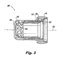
- the fuel injector 200 is constructed similarly to fuel injector 100, but has an outer air cap 210 which includes at least one slotted outer air flow channel 222 radially outboard of the fuel passage 212.
- the flow channel 222 defines the outer air circuit, which appears much like that described above with respect to Fig. 1 .
- Flow channel 222 can converge downstream towards longitudinal axis 224 of nozzle 200 at an angle of about thirty-five degrees or less, preferably between 15-20 degrees, and preferably closer to 15 degrees.
- Flow channel 222 can alternatively be oriented parallel with the longitudinal axis 224.
- Inner air swirler 202 includes an upstream dome 240 with a plurality of cylindrical swirl bores 242 defined therethrough for passage of compressor discharge air into inner air swirler 202. Cylindrical bores 242 of dome 240 are radially offset and converge downstream relative to longitudinal axis 224.
- Fuel passage 212 includes a multi-start threaded passage 226 defined between inner air swirler 202 and outer air cap 210 for swirling the fuel and providing even fuel distribution at low pressures.
- Inner air swirler 202 and the outer air circuit can be configured and adapted to pass about 30-60% of the total airflow of injector 200 through inner air swirler 202, with a preferred range of 40-45%, preferably closer to 40% while still utilizing the same overall diameter as nozzle 100.
- the actual flow area for a given air swirler is affected by the degree of swirl it generates.
- a straight radial slot has an effective flow area equal to approximately the mean diameter of the slot times the slot height times pi (3.14159). This area minus blockage area caused by any struts in the slot represents the flow area available to air passing through the slot. If the air is swirled, then the slot's area must be increased inversely proportional to the cosine of the swirl angle to pass the same quantity of flow for the same pressure drop across the element (e.g., a swirling flow of 60 deg. will have a cosine of 0.5, and thus require twice the slot height of that of a non-swirling flow). Struts placed between bores 122 passing the outer air in nozzle 100 act as obstructions, and thus do not allow as much air to pass as the nearly continuous slot 222 of nozzle 200.
- both nozzles 100, 200 will pass more air than conventional nozzles utilizing a swirling flow of air. Obtaining a large proportion of airflow through a highly swirling core of a nozzle requires a relatively large inner passage because of the high degree of swirl and its radially inner location in the nozzle. Therefore, the core passages utilized by nozzles 100, 200 are large relative to the overall diameters thereof. While both nozzles 100, 200 will pass more flow than conventional swirled nozzles of similar diameter, nozzle 200 will pass more air than nozzle 100.
- nozzle 200 also eliminates any gaps in the external air flow which may otherwise allow some fuel to prematurely escape the injector flow field. Nozzle 200 produces a higher quantity of swirling air through the core, and promotes a higher level of mixing between the inner and outer air layers compared to conventional configurations.
- nozzles 100, 200 may be utilized for very lean combustion (e.g., combustion with a ratio of mass flow of air to fuel greater than 15 to 1, and even greater than 30 to 1 at full power conditions (e.g., full engine power with pressure ratios greater than 55 tol).
- the outer diameter of nozzles 100, 200 can vary between one to two inches, with a preferred size of approximately 1.1 inches to 1.4 inches. This size is large enough to keep the total number of nozzles required to a minimum, but not so large that it unduly affects the size of the combustor.
- nozzles 100, 200 may be used with conventional air to fuel ratios, they may also be utilized to maximize an air flow having some degree of swirl for enhanced mixing capability through the smallest diameter possible as described above.
Landscapes
- Engineering & Computer Science (AREA)
- Chemical & Material Sciences (AREA)
- Combustion & Propulsion (AREA)
- Mechanical Engineering (AREA)
- General Engineering & Computer Science (AREA)
- Fuel-Injection Apparatus (AREA)
Applications Claiming Priority (2)
| Application Number | Priority Date | Filing Date | Title |
|---|---|---|---|
| US201161555363P | 2011-11-03 | 2011-11-03 | |
| US13/665,497 US9188063B2 (en) | 2011-11-03 | 2012-10-31 | Injectors for multipoint injection |
Publications (3)
| Publication Number | Publication Date |
|---|---|
| EP2589867A2 true EP2589867A2 (de) | 2013-05-08 |
| EP2589867A3 EP2589867A3 (de) | 2015-01-07 |
| EP2589867B1 EP2589867B1 (de) | 2016-07-20 |
Family
ID=47227497
Family Applications (1)
| Application Number | Title | Priority Date | Filing Date |
|---|---|---|---|
| EP12191142.4A Active EP2589867B1 (de) | 2011-11-03 | 2012-11-02 | Injektor für Mehrpunkteinspritzung |
Country Status (2)
| Country | Link |
|---|---|
| US (2) | US9188063B2 (de) |
| EP (1) | EP2589867B1 (de) |
Cited By (3)
| Publication number | Priority date | Publication date | Assignee | Title |
|---|---|---|---|---|
| EP2775202A3 (de) * | 2013-03-04 | 2015-01-07 | Delavan Inc. | Luftwirbler |
| US9927126B2 (en) | 2015-06-10 | 2018-03-27 | General Electric Company | Prefilming air blast (PAB) pilot for low emissions combustors |
| US10184665B2 (en) | 2015-06-10 | 2019-01-22 | General Electric Company | Prefilming air blast (PAB) pilot having annular splitter surrounding a pilot fuel injector |
Families Citing this family (18)
| Publication number | Priority date | Publication date | Assignee | Title |
|---|---|---|---|---|
| US10252270B2 (en) * | 2014-09-08 | 2019-04-09 | Arizona Board Of Regents On Behalf Of Arizona State University | Nozzle apparatus and methods for use thereof |
| JP6440433B2 (ja) * | 2014-09-29 | 2018-12-19 | 川崎重工業株式会社 | 燃料噴射ノズル、燃料噴射モジュール、及びガスタービン |
| US9901944B2 (en) | 2015-02-18 | 2018-02-27 | Delavan Inc | Atomizers |
| US10132500B2 (en) | 2015-10-16 | 2018-11-20 | Delavan Inc. | Airblast injectors |
| US10047959B2 (en) * | 2015-12-29 | 2018-08-14 | Pratt & Whitney Canada Corp. | Fuel injector for fuel spray nozzle |
| US10344981B2 (en) * | 2016-12-16 | 2019-07-09 | Delavan Inc. | Staged dual fuel radial nozzle with radial liquid fuel distributor |
| US10634355B2 (en) * | 2016-12-16 | 2020-04-28 | Delavan Inc. | Dual fuel radial flow nozzles |
| US10527286B2 (en) * | 2016-12-16 | 2020-01-07 | Delavan, Inc | Staged radial air swirler with radial liquid fuel distributor |
| KR101889542B1 (ko) * | 2017-04-18 | 2018-08-17 | 두산중공업 주식회사 | 연소기 노즐 조립체 및 이를 포함하는 가스터빈 |
| US11131459B2 (en) * | 2017-09-26 | 2021-09-28 | Delavan Inc. | Combustor with an air mixer and an air swirler each having slots |
| US20190186742A1 (en) * | 2017-12-15 | 2019-06-20 | Delavan, Inc. | Tapered helical fuel distributor |
| US11619388B2 (en) | 2017-12-21 | 2023-04-04 | Collins Engine Nozzles, Inc. | Dual fuel gas turbine engine pilot nozzles |
| US11892167B2 (en) * | 2020-01-22 | 2024-02-06 | Turbogen Ltd. | Atomizer for gas turbine engine |
| US11466859B2 (en) * | 2020-12-18 | 2022-10-11 | Pratt & Whitney Canada Corp. | Gap filler for a fuel system gallery |
| US20220412264A1 (en) * | 2021-06-24 | 2022-12-29 | Delavan Inc. | Radial equilibrated combustion nozzle array |
| US20230167975A1 (en) * | 2021-11-26 | 2023-06-01 | Pratt & Whitney Canada Corp. | Fuel nozzle with restricted core air passage |
| JP2024101934A (ja) * | 2023-01-18 | 2024-07-30 | トヨタ自動車株式会社 | 水素ガスタービンに適した燃焼器及びその燃焼ノズル |
| US20250327570A1 (en) * | 2024-04-22 | 2025-10-23 | General Electric Company | Fuel injector for a turbine engine |
Family Cites Families (75)
| Publication number | Priority date | Publication date | Assignee | Title |
|---|---|---|---|---|
| US1875457A (en) | 1932-09-06 | Torkild valdemar hemmingsen | ||
| BE488386A (de) | ||||
| US2607193A (en) | 1947-10-25 | 1952-08-19 | Curtiss Wright Corp | Annular combustion chamber with multiple notched fuel nozzles |
| US3530667A (en) * | 1967-11-02 | 1970-09-29 | Rolls Royce | Fuel injector for gas turbine engines |
| US3720058A (en) | 1970-01-02 | 1973-03-13 | Gen Electric | Combustor and fuel injector |
| US3680793A (en) | 1970-11-09 | 1972-08-01 | Delavan Manufacturing Co | Eccentric spiral swirl chamber nozzle |
| US3912164A (en) * | 1971-01-11 | 1975-10-14 | Parker Hannifin Corp | Method of liquid fuel injection, and to air blast atomizers |
| GB1421399A (en) | 1972-11-13 | 1976-01-14 | Snecma | Fuel injectors |
| US3980233A (en) * | 1974-10-07 | 1976-09-14 | Parker-Hannifin Corporation | Air-atomizing fuel nozzle |
| US3943705A (en) | 1974-11-15 | 1976-03-16 | Westinghouse Electric Corporation | Wide range catalytic combustor |
| JPS57187531A (en) | 1981-05-12 | 1982-11-18 | Hitachi Ltd | Low nox gas turbine burner |
| US4600151A (en) | 1982-11-23 | 1986-07-15 | Ex-Cell-O Corporation | Fuel injector assembly with water or auxiliary fuel capability |
| DE3525161A1 (de) * | 1985-03-05 | 1986-09-11 | DFVLR-Deutsche Forschungs- und Versuchsanstalt für Luft- und Raumfahrt e.V., 5000 Köln | Verfahren und vorrichtung zur verschleissarmen zerstaeubung von fluessigen hochviskosen und/oder suspensiven brennstoffen fuer die verbrennung oder vergasung in brennerflammen |
| US4653278A (en) | 1985-08-23 | 1987-03-31 | General Electric Company | Gas turbine engine carburetor |
| DE3856185D1 (de) | 1987-12-11 | 1998-06-18 | Deutsch Zentr Luft & Raumfahrt | Dralldüse zum Zerstäuben einer Flüssigkeit |
| US4941617A (en) * | 1988-12-14 | 1990-07-17 | United Technologies Corporation | Airblast fuel nozzle |
| US5409169A (en) | 1991-06-19 | 1995-04-25 | Hitachi America, Ltd. | Air-assist fuel injection system |
| US5361586A (en) | 1993-04-15 | 1994-11-08 | Westinghouse Electric Corporation | Gas turbine ultra low NOx combustor |
| FR2721694B1 (fr) | 1994-06-22 | 1996-07-19 | Snecma | Refroidissement de l'injecteur de décollage d'une chambre de combustion à deux têtes. |
| US5860600A (en) * | 1996-10-01 | 1999-01-19 | Todd Combustion | Atomizer (low opacity) |
| DE19645961A1 (de) | 1996-11-07 | 1998-05-14 | Bmw Rolls Royce Gmbh | Kraftstoffeinspritzvorrichtung für eine Gasturbinen-Brennkammer mit einer flüssigkeitsgekühlten Einspritzdüse |
| GB2319078B (en) | 1996-11-08 | 1999-11-03 | Europ Gas Turbines Ltd | Combustor arrangement |
| US6082113A (en) | 1998-05-22 | 2000-07-04 | Pratt & Whitney Canada Corp. | Gas turbine fuel injector |
| US6092363A (en) | 1998-06-19 | 2000-07-25 | Siemens Westinghouse Power Corporation | Low Nox combustor having dual fuel injection system |
| US6533954B2 (en) | 2000-02-28 | 2003-03-18 | Parker-Hannifin Corporation | Integrated fluid injection air mixing system |
| US6363726B1 (en) | 2000-09-29 | 2002-04-02 | General Electric Company | Mixer having multiple swirlers |
| FR2817017B1 (fr) | 2000-11-21 | 2003-03-07 | Snecma Moteurs | Refroidissement integral des injecteurs de decollage d'une chambre de combustion a deux tetes |
| US6688534B2 (en) | 2001-03-07 | 2004-02-10 | Delavan Inc | Air assist fuel nozzle |
| US6622488B2 (en) | 2001-03-21 | 2003-09-23 | Parker-Hannifin Corporation | Pure airblast nozzle |
| US6543235B1 (en) * | 2001-08-08 | 2003-04-08 | Cfd Research Corporation | Single-circuit fuel injector for gas turbine combustors |
| US6755024B1 (en) | 2001-08-23 | 2004-06-29 | Delavan Inc. | Multiplex injector |
| US6854670B2 (en) | 2002-05-17 | 2005-02-15 | Keihin Corporation | Fuel injection valve |
| US7028484B2 (en) | 2002-08-30 | 2006-04-18 | Pratt & Whitney Canada Corp. | Nested channel ducts for nozzle construction and the like |
| US6962055B2 (en) | 2002-09-27 | 2005-11-08 | United Technologies Corporation | Multi-point staging strategy for low emission and stable combustion |
| US6863228B2 (en) | 2002-09-30 | 2005-03-08 | Delavan Inc. | Discrete jet atomizer |
| US6871488B2 (en) * | 2002-12-17 | 2005-03-29 | Pratt & Whitney Canada Corp. | Natural gas fuel nozzle for gas turbine engine |
| JP2006524091A (ja) | 2003-04-24 | 2006-10-26 | コーニンクレッカ フィリップス エレクトロニクス エヌ ヴィ | カテーテルヘッド |
| JP4065947B2 (ja) * | 2003-08-05 | 2008-03-26 | 独立行政法人 宇宙航空研究開発機構 | ガスタービン燃焼器用燃料・空気プレミキサー |
| JP2005061715A (ja) | 2003-08-13 | 2005-03-10 | Ishikawajima Harima Heavy Ind Co Ltd | 希薄予蒸発予混合燃焼器 |
| DE10348604A1 (de) | 2003-10-20 | 2005-07-28 | Rolls-Royce Deutschland Ltd & Co Kg | Kraftstoffeinspritzdüse mit filmartiger Kraftstoffplatzierung |
| US7174717B2 (en) | 2003-12-24 | 2007-02-13 | Pratt & Whitney Canada Corp. | Helical channel fuel distributor and method |
| US7654088B2 (en) | 2004-02-27 | 2010-02-02 | Pratt & Whitney Canada Corp. | Dual conduit fuel manifold for gas turbine engine |
| US7350357B2 (en) | 2004-05-11 | 2008-04-01 | United Technologies Corporation | Nozzle |
| US8348180B2 (en) | 2004-06-09 | 2013-01-08 | Delavan Inc | Conical swirler for fuel injectors and combustor domes and methods of manufacturing the same |
| US7533531B2 (en) | 2005-04-01 | 2009-05-19 | Pratt & Whitney Canada Corp. | Internal fuel manifold with airblast nozzles |
| US7878000B2 (en) | 2005-12-20 | 2011-02-01 | General Electric Company | Pilot fuel injector for mixer assembly of a high pressure gas turbine engine |
| FR2896030B1 (fr) | 2006-01-09 | 2008-04-18 | Snecma Sa | Refroidissement d'un dispositif d'injection multimode pour chambre de combustion, notamment d'un turboreacteur |
| US7520134B2 (en) | 2006-09-29 | 2009-04-21 | General Electric Company | Methods and apparatus for injecting fluids into a turbine engine |
| GB0625016D0 (en) * | 2006-12-15 | 2007-01-24 | Rolls Royce Plc | Fuel injector |
| FR2911667B1 (fr) * | 2007-01-23 | 2009-10-02 | Snecma Sa | Systeme d'injection de carburant a double injecteur. |
| US8015796B2 (en) | 2007-06-05 | 2011-09-13 | United Technologies Corporation | Gas turbine engine with dual fans driven about a central core axis |
| FR2919898B1 (fr) | 2007-08-10 | 2014-08-22 | Snecma | Injecteur multipoint pour turbomachine |
| US7861528B2 (en) * | 2007-08-21 | 2011-01-04 | General Electric Company | Fuel nozzle and diffusion tip therefor |
| US20090111063A1 (en) | 2007-10-29 | 2009-04-30 | General Electric Company | Lean premixed, radial inflow, multi-annular staged nozzle, can-annular, dual-fuel combustor |
| US7926178B2 (en) | 2007-11-30 | 2011-04-19 | Delavan Inc | Method of fuel nozzle construction |
| US7926282B2 (en) | 2008-03-04 | 2011-04-19 | Delavan Inc | Pure air blast fuel injector |
| US20090255258A1 (en) | 2008-04-11 | 2009-10-15 | Delavan Inc | Pre-filming air-blast fuel injector having a reduced hydraulic spray angle |
| US8806871B2 (en) | 2008-04-11 | 2014-08-19 | General Electric Company | Fuel nozzle |
| US8096135B2 (en) | 2008-05-06 | 2012-01-17 | Dela Van Inc | Pure air blast fuel injector |
| US8347630B2 (en) | 2008-09-03 | 2013-01-08 | United Technologies Corp | Air-blast fuel-injector with shield-cone upstream of fuel orifices |
| US8272218B2 (en) * | 2008-09-24 | 2012-09-25 | Siemens Energy, Inc. | Spiral cooled fuel nozzle |
| GB0820560D0 (en) | 2008-11-11 | 2008-12-17 | Rolls Royce Plc | Fuel injector |
| US8313046B2 (en) | 2009-08-04 | 2012-11-20 | Delavan Inc | Multi-point injector ring |
| US8663348B2 (en) | 2010-08-11 | 2014-03-04 | General Electric Company | Apparatus for removing heat from injection devices and method of assembling same |
| US10317081B2 (en) | 2011-01-26 | 2019-06-11 | United Technologies Corporation | Fuel injector assembly |
| US9383097B2 (en) | 2011-03-10 | 2016-07-05 | Rolls-Royce Plc | Systems and method for cooling a staged airblast fuel injector |
| US8925325B2 (en) | 2011-03-18 | 2015-01-06 | Delavan Inc. | Recirculating product injection nozzle |
| RU2604260C2 (ru) | 2011-05-17 | 2016-12-10 | Снекма | Кольцевая камера сгорания для турбомашины |
| US20140339339A1 (en) | 2011-11-03 | 2014-11-20 | Delavan Inc | Airblast injectors for multipoint injection and methods of assembly |
| US9441836B2 (en) | 2012-07-10 | 2016-09-13 | United Technologies Corporation | Fuel-air pre-mixer with prefilmer |
| US10161633B2 (en) | 2013-03-04 | 2018-12-25 | Delavan Inc. | Air swirlers |
| US9592480B2 (en) | 2013-05-13 | 2017-03-14 | Solar Turbines Incorporated | Inner premix tube air wipe |
| EP3011231B1 (de) | 2013-06-18 | 2019-10-30 | Woodward, Inc. | Gasturbinenbrennkammeranordnung |
| US9897321B2 (en) | 2015-03-31 | 2018-02-20 | Delavan Inc. | Fuel nozzles |
| US10385809B2 (en) | 2015-03-31 | 2019-08-20 | Delavan Inc. | Fuel nozzles |
-
2012
- 2012-10-31 US US13/665,497 patent/US9188063B2/en active Active
- 2012-11-02 EP EP12191142.4A patent/EP2589867B1/de active Active
-
2015
- 2015-08-25 US US14/835,654 patent/US10309651B2/en active Active
Non-Patent Citations (1)
| Title |
|---|
| None |
Cited By (4)
| Publication number | Priority date | Publication date | Assignee | Title |
|---|---|---|---|---|
| EP2775202A3 (de) * | 2013-03-04 | 2015-01-07 | Delavan Inc. | Luftwirbler |
| US10161633B2 (en) | 2013-03-04 | 2018-12-25 | Delavan Inc. | Air swirlers |
| US9927126B2 (en) | 2015-06-10 | 2018-03-27 | General Electric Company | Prefilming air blast (PAB) pilot for low emissions combustors |
| US10184665B2 (en) | 2015-06-10 | 2019-01-22 | General Electric Company | Prefilming air blast (PAB) pilot having annular splitter surrounding a pilot fuel injector |
Also Published As
| Publication number | Publication date |
|---|---|
| EP2589867B1 (de) | 2016-07-20 |
| US9188063B2 (en) | 2015-11-17 |
| US10309651B2 (en) | 2019-06-04 |
| EP2589867A3 (de) | 2015-01-07 |
| US20150361896A1 (en) | 2015-12-17 |
| US20140338337A1 (en) | 2014-11-20 |
Similar Documents
| Publication | Publication Date | Title |
|---|---|---|
| US9188063B2 (en) | Injectors for multipoint injection | |
| US9752781B2 (en) | Flamesheet combustor dome | |
| US9644844B2 (en) | Multipoint fuel injection arrangements | |
| US6272840B1 (en) | Piloted airblast lean direct fuel injector | |
| US6474569B1 (en) | Fuel injector | |
| US10125993B2 (en) | Burner, gas turbine having such a burner, and fuel nozzle | |
| US9182124B2 (en) | Gas turbine and fuel injector for the same | |
| US20130104554A1 (en) | Burner assembly | |
| EP2400220A2 (de) | Wirbler, Kraftstoff- und Luftbaugruppe und Verbrenner | |
| EP3059497A2 (de) | Verbesserte turbulente vermischung | |
| US10036552B2 (en) | Injection system for a combustion chamber of a turbine engine, comprising an annular wall having a convergent inner cross-section | |
| KR20160143715A (ko) | 저공해 가스 터빈 연소기를 위한 공기 연료 예혼합기 | |
| US20190170354A1 (en) | Fuel spray nozzle | |
| WO2004071637A1 (en) | Mixer | |
| US20150300646A1 (en) | Method for premixing air with a gaseous fuel and burner arrangement for conducting said method | |
| EP2778533A2 (de) | Verbrenner für Gasturbinentriebwerk | |
| US10352570B2 (en) | Turbine engine fuel injection system and methods of assembling the same | |
| US20130180251A1 (en) | Burner arrangement | |
| US9803864B2 (en) | Turbine air flow conditioner | |
| US9404658B2 (en) | Gas turbine engine fuel air mixer | |
| US10295191B2 (en) | Gas turbine engine and annular combustor with swirler | |
| Prociw et al. | Injectors for Multipoint Injection | |
| US10724741B2 (en) | Combustors and methods of assembling the same | |
| US8950189B2 (en) | Gas turbine engine staged fuel injection using adjacent bluff body and swirler fuel injectors | |
| US20130152594A1 (en) | Gas turbine and fuel injector for the same |
Legal Events
| Date | Code | Title | Description |
|---|---|---|---|
| PUAI | Public reference made under article 153(3) epc to a published international application that has entered the european phase |
Free format text: ORIGINAL CODE: 0009012 |
|
| 17P | Request for examination filed |
Effective date: 20121102 |
|
| AK | Designated contracting states |
Kind code of ref document: A2 Designated state(s): AL AT BE BG CH CY CZ DE DK EE ES FI FR GB GR HR HU IE IS IT LI LT LU LV MC MK MT NL NO PL PT RO RS SE SI SK SM TR |
|
| AX | Request for extension of the european patent |
Extension state: BA ME |
|
| PUAL | Search report despatched |
Free format text: ORIGINAL CODE: 0009013 |
|
| AK | Designated contracting states |
Kind code of ref document: A3 Designated state(s): AL AT BE BG CH CY CZ DE DK EE ES FI FR GB GR HR HU IE IS IT LI LT LU LV MC MK MT NL NO PL PT RO RS SE SI SK SM TR |
|
| AX | Request for extension of the european patent |
Extension state: BA ME |
|
| RIC1 | Information provided on ipc code assigned before grant |
Ipc: F23D 11/10 20060101AFI20141128BHEP Ipc: F23R 3/28 20060101ALI20141128BHEP |
|
| GRAP | Despatch of communication of intention to grant a patent |
Free format text: ORIGINAL CODE: EPIDOSNIGR1 |
|
| INTG | Intention to grant announced |
Effective date: 20160127 |
|
| GRAS | Grant fee paid |
Free format text: ORIGINAL CODE: EPIDOSNIGR3 |
|
| GRAA | (expected) grant |
Free format text: ORIGINAL CODE: 0009210 |
|
| AK | Designated contracting states |
Kind code of ref document: B1 Designated state(s): AL AT BE BG CH CY CZ DE DK EE ES FI FR GB GR HR HU IE IS IT LI LT LU LV MC MK MT NL NO PL PT RO RS SE SI SK SM TR |
|
| REG | Reference to a national code |
Ref country code: GB Ref legal event code: FG4D |
|
| REG | Reference to a national code |
Ref country code: CH Ref legal event code: EP |
|
| REG | Reference to a national code |
Ref country code: IE Ref legal event code: FG4D |
|
| REG | Reference to a national code |
Ref country code: AT Ref legal event code: REF Ref document number: 814425 Country of ref document: AT Kind code of ref document: T Effective date: 20160815 |
|
| REG | Reference to a national code |
Ref country code: DE Ref legal event code: R096 Ref document number: 602012020649 Country of ref document: DE |
|
| REG | Reference to a national code |
Ref country code: FR Ref legal event code: PLFP Year of fee payment: 5 |
|
| REG | Reference to a national code |
Ref country code: LT Ref legal event code: MG4D |
|
| REG | Reference to a national code |
Ref country code: NL Ref legal event code: MP Effective date: 20160720 |
|
| REG | Reference to a national code |
Ref country code: AT Ref legal event code: MK05 Ref document number: 814425 Country of ref document: AT Kind code of ref document: T Effective date: 20160720 |
|
| PG25 | Lapsed in a contracting state [announced via postgrant information from national office to epo] |
Ref country code: IT Free format text: LAPSE BECAUSE OF FAILURE TO SUBMIT A TRANSLATION OF THE DESCRIPTION OR TO PAY THE FEE WITHIN THE PRESCRIBED TIME-LIMIT Effective date: 20160720 Ref country code: RS Free format text: LAPSE BECAUSE OF FAILURE TO SUBMIT A TRANSLATION OF THE DESCRIPTION OR TO PAY THE FEE WITHIN THE PRESCRIBED TIME-LIMIT Effective date: 20160720 Ref country code: IS Free format text: LAPSE BECAUSE OF FAILURE TO SUBMIT A TRANSLATION OF THE DESCRIPTION OR TO PAY THE FEE WITHIN THE PRESCRIBED TIME-LIMIT Effective date: 20161120 Ref country code: NO Free format text: LAPSE BECAUSE OF FAILURE TO SUBMIT A TRANSLATION OF THE DESCRIPTION OR TO PAY THE FEE WITHIN THE PRESCRIBED TIME-LIMIT Effective date: 20161020 Ref country code: FI Free format text: LAPSE BECAUSE OF FAILURE TO SUBMIT A TRANSLATION OF THE DESCRIPTION OR TO PAY THE FEE WITHIN THE PRESCRIBED TIME-LIMIT Effective date: 20160720 Ref country code: HR Free format text: LAPSE BECAUSE OF FAILURE TO SUBMIT A TRANSLATION OF THE DESCRIPTION OR TO PAY THE FEE WITHIN THE PRESCRIBED TIME-LIMIT Effective date: 20160720 Ref country code: NL Free format text: LAPSE BECAUSE OF FAILURE TO SUBMIT A TRANSLATION OF THE DESCRIPTION OR TO PAY THE FEE WITHIN THE PRESCRIBED TIME-LIMIT Effective date: 20160720 Ref country code: LT Free format text: LAPSE BECAUSE OF FAILURE TO SUBMIT A TRANSLATION OF THE DESCRIPTION OR TO PAY THE FEE WITHIN THE PRESCRIBED TIME-LIMIT Effective date: 20160720 |
|
| PG25 | Lapsed in a contracting state [announced via postgrant information from national office to epo] |
Ref country code: SE Free format text: LAPSE BECAUSE OF FAILURE TO SUBMIT A TRANSLATION OF THE DESCRIPTION OR TO PAY THE FEE WITHIN THE PRESCRIBED TIME-LIMIT Effective date: 20160720 Ref country code: LV Free format text: LAPSE BECAUSE OF FAILURE TO SUBMIT A TRANSLATION OF THE DESCRIPTION OR TO PAY THE FEE WITHIN THE PRESCRIBED TIME-LIMIT Effective date: 20160720 Ref country code: ES Free format text: LAPSE BECAUSE OF FAILURE TO SUBMIT A TRANSLATION OF THE DESCRIPTION OR TO PAY THE FEE WITHIN THE PRESCRIBED TIME-LIMIT Effective date: 20160720 Ref country code: GR Free format text: LAPSE BECAUSE OF FAILURE TO SUBMIT A TRANSLATION OF THE DESCRIPTION OR TO PAY THE FEE WITHIN THE PRESCRIBED TIME-LIMIT Effective date: 20161021 Ref country code: BE Free format text: LAPSE BECAUSE OF NON-PAYMENT OF DUE FEES Effective date: 20160720 Ref country code: PT Free format text: LAPSE BECAUSE OF FAILURE TO SUBMIT A TRANSLATION OF THE DESCRIPTION OR TO PAY THE FEE WITHIN THE PRESCRIBED TIME-LIMIT Effective date: 20161121 Ref country code: AT Free format text: LAPSE BECAUSE OF FAILURE TO SUBMIT A TRANSLATION OF THE DESCRIPTION OR TO PAY THE FEE WITHIN THE PRESCRIBED TIME-LIMIT Effective date: 20160720 Ref country code: PL Free format text: LAPSE BECAUSE OF FAILURE TO SUBMIT A TRANSLATION OF THE DESCRIPTION OR TO PAY THE FEE WITHIN THE PRESCRIBED TIME-LIMIT Effective date: 20160720 |
|
| REG | Reference to a national code |
Ref country code: DE Ref legal event code: R097 Ref document number: 602012020649 Country of ref document: DE |
|
| PG25 | Lapsed in a contracting state [announced via postgrant information from national office to epo] |
Ref country code: RO Free format text: LAPSE BECAUSE OF FAILURE TO SUBMIT A TRANSLATION OF THE DESCRIPTION OR TO PAY THE FEE WITHIN THE PRESCRIBED TIME-LIMIT Effective date: 20160720 Ref country code: EE Free format text: LAPSE BECAUSE OF FAILURE TO SUBMIT A TRANSLATION OF THE DESCRIPTION OR TO PAY THE FEE WITHIN THE PRESCRIBED TIME-LIMIT Effective date: 20160720 |
|
| PLBE | No opposition filed within time limit |
Free format text: ORIGINAL CODE: 0009261 |
|
| STAA | Information on the status of an ep patent application or granted ep patent |
Free format text: STATUS: NO OPPOSITION FILED WITHIN TIME LIMIT |
|
| PG25 | Lapsed in a contracting state [announced via postgrant information from national office to epo] |
Ref country code: SK Free format text: LAPSE BECAUSE OF FAILURE TO SUBMIT A TRANSLATION OF THE DESCRIPTION OR TO PAY THE FEE WITHIN THE PRESCRIBED TIME-LIMIT Effective date: 20160720 Ref country code: SM Free format text: LAPSE BECAUSE OF FAILURE TO SUBMIT A TRANSLATION OF THE DESCRIPTION OR TO PAY THE FEE WITHIN THE PRESCRIBED TIME-LIMIT Effective date: 20160720 Ref country code: CZ Free format text: LAPSE BECAUSE OF FAILURE TO SUBMIT A TRANSLATION OF THE DESCRIPTION OR TO PAY THE FEE WITHIN THE PRESCRIBED TIME-LIMIT Effective date: 20160720 Ref country code: DK Free format text: LAPSE BECAUSE OF FAILURE TO SUBMIT A TRANSLATION OF THE DESCRIPTION OR TO PAY THE FEE WITHIN THE PRESCRIBED TIME-LIMIT Effective date: 20160720 Ref country code: BG Free format text: LAPSE BECAUSE OF FAILURE TO SUBMIT A TRANSLATION OF THE DESCRIPTION OR TO PAY THE FEE WITHIN THE PRESCRIBED TIME-LIMIT Effective date: 20161020 |
|
| 26N | No opposition filed |
Effective date: 20170421 |
|
| REG | Reference to a national code |
Ref country code: CH Ref legal event code: PL |
|
| PG25 | Lapsed in a contracting state [announced via postgrant information from national office to epo] |
Ref country code: CH Free format text: LAPSE BECAUSE OF NON-PAYMENT OF DUE FEES Effective date: 20161130 Ref country code: LI Free format text: LAPSE BECAUSE OF NON-PAYMENT OF DUE FEES Effective date: 20161130 |
|
| REG | Reference to a national code |
Ref country code: IE Ref legal event code: MM4A |
|
| PG25 | Lapsed in a contracting state [announced via postgrant information from national office to epo] |
Ref country code: SI Free format text: LAPSE BECAUSE OF FAILURE TO SUBMIT A TRANSLATION OF THE DESCRIPTION OR TO PAY THE FEE WITHIN THE PRESCRIBED TIME-LIMIT Effective date: 20160720 |
|
| PG25 | Lapsed in a contracting state [announced via postgrant information from national office to epo] |
Ref country code: LU Free format text: LAPSE BECAUSE OF NON-PAYMENT OF DUE FEES Effective date: 20161130 |
|
| REG | Reference to a national code |
Ref country code: FR Ref legal event code: PLFP Year of fee payment: 6 |
|
| PG25 | Lapsed in a contracting state [announced via postgrant information from national office to epo] |
Ref country code: IE Free format text: LAPSE BECAUSE OF NON-PAYMENT OF DUE FEES Effective date: 20161102 |
|
| PG25 | Lapsed in a contracting state [announced via postgrant information from national office to epo] |
Ref country code: CY Free format text: LAPSE BECAUSE OF FAILURE TO SUBMIT A TRANSLATION OF THE DESCRIPTION OR TO PAY THE FEE WITHIN THE PRESCRIBED TIME-LIMIT Effective date: 20160720 Ref country code: HU Free format text: LAPSE BECAUSE OF FAILURE TO SUBMIT A TRANSLATION OF THE DESCRIPTION OR TO PAY THE FEE WITHIN THE PRESCRIBED TIME-LIMIT; INVALID AB INITIO Effective date: 20121102 |
|
| PG25 | Lapsed in a contracting state [announced via postgrant information from national office to epo] |
Ref country code: MK Free format text: LAPSE BECAUSE OF FAILURE TO SUBMIT A TRANSLATION OF THE DESCRIPTION OR TO PAY THE FEE WITHIN THE PRESCRIBED TIME-LIMIT Effective date: 20160720 Ref country code: TR Free format text: LAPSE BECAUSE OF FAILURE TO SUBMIT A TRANSLATION OF THE DESCRIPTION OR TO PAY THE FEE WITHIN THE PRESCRIBED TIME-LIMIT Effective date: 20160720 Ref country code: MC Free format text: LAPSE BECAUSE OF FAILURE TO SUBMIT A TRANSLATION OF THE DESCRIPTION OR TO PAY THE FEE WITHIN THE PRESCRIBED TIME-LIMIT Effective date: 20160720 |
|
| PG25 | Lapsed in a contracting state [announced via postgrant information from national office to epo] |
Ref country code: MT Free format text: LAPSE BECAUSE OF NON-PAYMENT OF DUE FEES Effective date: 20161102 |
|
| REG | Reference to a national code |
Ref country code: FR Ref legal event code: PLFP Year of fee payment: 7 |
|
| PG25 | Lapsed in a contracting state [announced via postgrant information from national office to epo] |
Ref country code: AL Free format text: LAPSE BECAUSE OF FAILURE TO SUBMIT A TRANSLATION OF THE DESCRIPTION OR TO PAY THE FEE WITHIN THE PRESCRIBED TIME-LIMIT Effective date: 20160720 |
|
| REG | Reference to a national code |
Ref country code: DE Ref legal event code: R082 Ref document number: 602012020649 Country of ref document: DE |
|
| P01 | Opt-out of the competence of the unified patent court (upc) registered |
Effective date: 20230530 |
|
| PGFP | Annual fee paid to national office [announced via postgrant information from national office to epo] |
Ref country code: DE Payment date: 20251022 Year of fee payment: 14 |
|
| PGFP | Annual fee paid to national office [announced via postgrant information from national office to epo] |
Ref country code: GB Payment date: 20251023 Year of fee payment: 14 |
|
| PGFP | Annual fee paid to national office [announced via postgrant information from national office to epo] |
Ref country code: FR Payment date: 20251022 Year of fee payment: 14 |