EP2589815A1 - Impeller and method for producing same - Google Patents
Impeller and method for producing same Download PDFInfo
- Publication number
- EP2589815A1 EP2589815A1 EP11800575.0A EP11800575A EP2589815A1 EP 2589815 A1 EP2589815 A1 EP 2589815A1 EP 11800575 A EP11800575 A EP 11800575A EP 2589815 A1 EP2589815 A1 EP 2589815A1
- Authority
- EP
- European Patent Office
- Prior art keywords
- substrate
- impeller
- blade portion
- inner circumferential
- rotary shaft
- Prior art date
- Legal status (The legal status is an assumption and is not a legal conclusion. Google has not performed a legal analysis and makes no representation as to the accuracy of the status listed.)
- Withdrawn
Links
Images


Classifications
-
- F—MECHANICAL ENGINEERING; LIGHTING; HEATING; WEAPONS; BLASTING
- F01—MACHINES OR ENGINES IN GENERAL; ENGINE PLANTS IN GENERAL; STEAM ENGINES
- F01D—NON-POSITIVE DISPLACEMENT MACHINES OR ENGINES, e.g. STEAM TURBINES
- F01D5/00—Blades; Blade-carrying members; Heating, heat-insulating, cooling or antivibration means on the blades or the members
- F01D5/12—Blades
- F01D5/14—Form or construction
- F01D5/141—Shape, i.e. outer, aerodynamic form
-
- F—MECHANICAL ENGINEERING; LIGHTING; HEATING; WEAPONS; BLASTING
- F04—POSITIVE - DISPLACEMENT MACHINES FOR LIQUIDS; PUMPS FOR LIQUIDS OR ELASTIC FLUIDS
- F04D—NON-POSITIVE-DISPLACEMENT PUMPS
- F04D29/00—Details, component parts, or accessories
- F04D29/26—Rotors specially for elastic fluids
- F04D29/28—Rotors specially for elastic fluids for centrifugal or helico-centrifugal pumps for radial-flow or helico-centrifugal pumps
- F04D29/284—Rotors specially for elastic fluids for centrifugal or helico-centrifugal pumps for radial-flow or helico-centrifugal pumps for compressors
-
- B—PERFORMING OPERATIONS; TRANSPORTING
- B29—WORKING OF PLASTICS; WORKING OF SUBSTANCES IN A PLASTIC STATE IN GENERAL
- B29C—SHAPING OR JOINING OF PLASTICS; SHAPING OF MATERIAL IN A PLASTIC STATE, NOT OTHERWISE PROVIDED FOR; AFTER-TREATMENT OF THE SHAPED PRODUCTS, e.g. REPAIRING
- B29C53/00—Shaping by bending, folding, twisting, straightening or flattening; Apparatus therefor
- B29C53/02—Bending or folding
-
- B—PERFORMING OPERATIONS; TRANSPORTING
- B29—WORKING OF PLASTICS; WORKING OF SUBSTANCES IN A PLASTIC STATE IN GENERAL
- B29C—SHAPING OR JOINING OF PLASTICS; SHAPING OF MATERIAL IN A PLASTIC STATE, NOT OTHERWISE PROVIDED FOR; AFTER-TREATMENT OF THE SHAPED PRODUCTS, e.g. REPAIRING
- B29C67/00—Shaping techniques not covered by groups B29C39/00 - B29C65/00, B29C70/00 or B29C73/00
- B29C67/0048—Local deformation of formed objects
-
- F—MECHANICAL ENGINEERING; LIGHTING; HEATING; WEAPONS; BLASTING
- F04—POSITIVE - DISPLACEMENT MACHINES FOR LIQUIDS; PUMPS FOR LIQUIDS OR ELASTIC FLUIDS
- F04D—NON-POSITIVE-DISPLACEMENT PUMPS
- F04D13/00—Pumping installations or systems
- F04D13/02—Units comprising pumps and their driving means
- F04D13/06—Units comprising pumps and their driving means the pump being electrically driven
-
- F—MECHANICAL ENGINEERING; LIGHTING; HEATING; WEAPONS; BLASTING
- F04—POSITIVE - DISPLACEMENT MACHINES FOR LIQUIDS; PUMPS FOR LIQUIDS OR ELASTIC FLUIDS
- F04D—NON-POSITIVE-DISPLACEMENT PUMPS
- F04D29/00—Details, component parts, or accessories
- F04D29/18—Rotors
- F04D29/22—Rotors specially for centrifugal pumps
- F04D29/2205—Conventional flow pattern
- F04D29/2222—Construction and assembly
-
- F—MECHANICAL ENGINEERING; LIGHTING; HEATING; WEAPONS; BLASTING
- F04—POSITIVE - DISPLACEMENT MACHINES FOR LIQUIDS; PUMPS FOR LIQUIDS OR ELASTIC FLUIDS
- F04D—NON-POSITIVE-DISPLACEMENT PUMPS
- F04D29/00—Details, component parts, or accessories
- F04D29/18—Rotors
- F04D29/22—Rotors specially for centrifugal pumps
- F04D29/24—Vanes
- F04D29/242—Geometry, shape
-
- F—MECHANICAL ENGINEERING; LIGHTING; HEATING; WEAPONS; BLASTING
- F04—POSITIVE - DISPLACEMENT MACHINES FOR LIQUIDS; PUMPS FOR LIQUIDS OR ELASTIC FLUIDS
- F04D—NON-POSITIVE-DISPLACEMENT PUMPS
- F04D29/00—Details, component parts, or accessories
- F04D29/26—Rotors specially for elastic fluids
- F04D29/28—Rotors specially for elastic fluids for centrifugal or helico-centrifugal pumps for radial-flow or helico-centrifugal pumps
- F04D29/281—Rotors specially for elastic fluids for centrifugal or helico-centrifugal pumps for radial-flow or helico-centrifugal pumps for fans or blowers
-
- F—MECHANICAL ENGINEERING; LIGHTING; HEATING; WEAPONS; BLASTING
- F04—POSITIVE - DISPLACEMENT MACHINES FOR LIQUIDS; PUMPS FOR LIQUIDS OR ELASTIC FLUIDS
- F04D—NON-POSITIVE-DISPLACEMENT PUMPS
- F04D29/00—Details, component parts, or accessories
- F04D29/26—Rotors specially for elastic fluids
- F04D29/28—Rotors specially for elastic fluids for centrifugal or helico-centrifugal pumps for radial-flow or helico-centrifugal pumps
- F04D29/281—Rotors specially for elastic fluids for centrifugal or helico-centrifugal pumps for radial-flow or helico-centrifugal pumps for fans or blowers
- F04D29/282—Rotors specially for elastic fluids for centrifugal or helico-centrifugal pumps for radial-flow or helico-centrifugal pumps for fans or blowers the leading edge of each vane being substantially parallel to the rotation axis
-
- F—MECHANICAL ENGINEERING; LIGHTING; HEATING; WEAPONS; BLASTING
- F04—POSITIVE - DISPLACEMENT MACHINES FOR LIQUIDS; PUMPS FOR LIQUIDS OR ELASTIC FLUIDS
- F04D—NON-POSITIVE-DISPLACEMENT PUMPS
- F04D29/00—Details, component parts, or accessories
- F04D29/26—Rotors specially for elastic fluids
- F04D29/28—Rotors specially for elastic fluids for centrifugal or helico-centrifugal pumps for radial-flow or helico-centrifugal pumps
- F04D29/30—Vanes
-
- B—PERFORMING OPERATIONS; TRANSPORTING
- B29—WORKING OF PLASTICS; WORKING OF SUBSTANCES IN A PLASTIC STATE IN GENERAL
- B29L—INDEXING SCHEME ASSOCIATED WITH SUBCLASS B29C, RELATING TO PARTICULAR ARTICLES
- B29L2031/00—Other particular articles
- B29L2031/08—Blades for rotors, stators, fans, turbines or the like, e.g. screw propellers
-
- B—PERFORMING OPERATIONS; TRANSPORTING
- B29—WORKING OF PLASTICS; WORKING OF SUBSTANCES IN A PLASTIC STATE IN GENERAL
- B29L—INDEXING SCHEME ASSOCIATED WITH SUBCLASS B29C, RELATING TO PARTICULAR ARTICLES
- B29L2031/00—Other particular articles
- B29L2031/748—Machines or parts thereof not otherwise provided for
- B29L2031/7498—Rotors
Definitions
- the present invention relates to an impeller that integrally includes a substrate and multiple impeller blades that are provided upright along a curved shape and spaced apart in a circumferential direction on one face of the substrate, the impeller blades each being configured by an inner circumferential-side blade portion arranged so as to be located on an inner circumferential side of the substrate and oriented so as to extend in a direction along a rotary shaft core and have a tip side that is bent, and an outer circumferential-side blade portion arranged so as to be located on an outer circumferential side of the substrate and oriented so as to extend in the direction along the rotary shaft core, and relates to a method for producing the same.
- the inner circumferential-side blade portion of the impeller blade is arranged so as to be located on the inner circumferential side of the substrate and oriented so as to extend in the direction along the rotary shaft core and have a tip side that is bent, thus enabling a fluid to be efficiently drawn from the inner circumferential side of the substrate by the inner circumferential-side blade portion.
- the impeller blade is divided into the inner circumferential-side blade portion and the outer circumferential-side blade portion, which are created separately, and then the inner circumferential-side blade portion and the outer circumferential-side blade portion are assembled so as to be integrated.
- the inner circumferential-side blade portion is provided so as to be integrated with the substrate of an inducer that is attached to the inlet side of the impeller, for example (e.g., see Patent Document 1).
- Patent Document 1 JP 2666490B
- the inner circumferential-side blade portion and the outer circumferential-side blade portion of the impeller blade need to be assembled so as to be integrated when producing the impeller, and there is the risk of an increase in the effort required for assembly.
- the inner circumferential-side blade portion which is oriented so as to extend in the direction along the rotary shaft core and have a tip side that is bent, has a three-dimensional shape. For this reason, in the case where an impeller that integrally includes a substrate and multiple impeller blades is produced by being formed using a die, there is the risk that the task of separating the molded piece from the die will be laborious, and that the production process for the impeller will become complicated.
- the present invention was achieved in light of the above-described circumstances, and an object thereof is to provide an impeller that can integrally include a substrate and impeller blades that are provided with a three-dimensional inner circumferential-side blade portion, and also achieve simplification in production.
- the impeller includes a substrate, and a plurality of impeller blades that are provided upright along a curved shape and spaced apart in a circumferential direction on one face of the substrate, wherein the impeller blades extend in the circumferential direction while expanding in diameter from a rotary shaft core side, the impeller blades are each configured by an inner circumferential-side blade portion arranged so as to be located on an inner circumferential side of the substrate and oriented so as to extend in a direction along a rotary shaft core and have a tip side that is bent, and an outer circumferential-side blade portion arranged so as to be located on an outer circumferential side of the substrate and oriented so as to extend in the direction along the rotary shaft core, with respect to the direction along the rotary shaft core, the length of the inner circumferential-side blade portion from the substrate side to the tip side is longer than the length of the outer circumferential-side blade portion from the substrate side to the tip side, and with respect
- the impeller blades extend in the circumferential direction while expanding in diameter from the rotary shaft core side, and with respect to the direction along the rotary shaft core, the length of the inner circumferential-side blade portion from the substrate side to the tip side is longer than the length of the outer circumferential-side blade portion from the substrate side to the tip side, and the blade thickness of the inner circumferential-side blade portion gradually decreases from the substrate side toward the tip side.
- the impeller in the production of the impeller, if the inner circumferential-side blade portion, whose length from the substrate side to the tip side in the direction along the rotary shaft core is longer than the length of the outer circumferential-side blade portion from the substrate side to the tip side, and whose blade thickness gradually decreases from the substrate side toward the tip side, is integrally provided on the substrate so as to have a two-dimensional shape projecting in the direction along the rotary shaft core, the impeller can be easily produced with a task of plastically deforming the inner circumferential-side blade portion into a three-dimensional shape by separately bending the tip side portion of the inner circumferential-side blade portion, which has a long length from the substrate side to the tip side and is easily bendable due to having a low blade thickness. Accordingly, with the impeller having this configuration, it is possible to integrally include a substrate and impeller blades that are provided with a three-dimensional inner circumferential-side blade portion, and also achieve simplification in production.
- the impeller includes a substrate, and a plurality of impeller blades that are provided upright along a curved shape and spaced apart in a circumferential direction on one face of the substrate, wherein the impeller blades are each provided upright such that an inner circumferential-side blade portion and an outer circumferential-side blade portion are continuous with each other, the inner circumferential-side blade portion being arranged so as to be located on an inner circumferential side of the substrate and oriented so as to extend in a direction along a rotary shaft core and have a tip side that is bent, and the outer circumferential-side blade portion being arranged so as to be located on an outer circumferential side of the substrate and oriented so as to extend in the direction along the rotary shaft core, with respect to the direction along the rotary shaft core, the length of the inner circumferential-side blade portion from the substrate side to the tip side is longer than the length of the outer circumferential-side blade portion from the substrate side to the tip side
- the impeller blades are provided upright such that the inner circumferential-side blade portion and the outer circumferential-side blade portion are continuous with each other, and with respect to the direction along the rotary shaft core, the length of the inner circumferential-side blade portion from the substrate side to the tip side is longer than the length of the outer circumferential-side blade portion from the substrate side to the tip side, and the blade thickness of the inner circumferential-side blade portion gradually decreases from the substrate side toward the tip side.
- the impeller in the production of the impeller, if the inner circumferential-side blade portion, whose length from the substrate side to the tip side in the direction along the rotary shaft core is longer than the length of the outer circumferential-side blade portion from the substrate side to the tip side, and whose blade thickness gradually decreases from the substrate side toward the tip side, is integrally provided on the substrate so as to have a two-dimensional shape projecting in the direction along the rotary shaft core, the impeller can be easily produced with a task of plastically deforming the inner circumferential-side blade portion into a three-dimensional shape by separately bending the tip side portion of the inner circumferential-side blade portion, which has a long length from the substrate side to the tip side and is easily bendable due to having a low blade thickness. Accordingly, with the impeller having this configuration, it is possible to integrally include a substrate and impeller blades that are provided with a three-dimensional inner circumferential-side blade portion, and also achieve simplification in production.
- a discontinuous portion at which a rate of gradual decrease in the blade thickness changes discontinuously may be provided along the curved shape of the inner circumferential-side blade portion, and the inner circumferential-side blade portion may be provided upright and oriented so as to be bent toward at least one of the outer circumferential side of the substrate and the inner circumferential side of the substrate along the discontinuous portion.
- the inner circumferential-side blade portion that is two-dimensional and integrally provided on the substrate when the inner circumferential-side blade portion that is two-dimensional and integrally provided on the substrate is plastically deformed into an orientation in which the tip side portion is bent toward at least one of the outer circumferential side of the substrate and the inner circumferential side of the substrate, the portion on the tip side of the discontinuous portion provided along the curved shape of the inner circumferential-side blade portion can be easily bent by focusing the bending force at the discontinuous portion. Accordingly, the inner circumferential-side blade portion can be easily plastically deformed into an orientation in which the tip side portion is bent toward at least one of the outer circumferential side of the substrate and the inner circumferential side of the substrate.
- the substrate may configure an impeller back plate, and a shroud that is to be assembled opposing the impeller back plate with the plurality of impeller blades sandwiched therebetween may be fixed to the outer circumferential-side blade portions of the impeller blades.
- the shroud is fixed to the outer circumferential-side blade portions of the impeller blades, that is to say, to the two-dimensional inner circumferential-side blade portions oriented so as to project in the direction along the rotary shaft core, and therefore the shroud can be easily and precisely fixed to the impeller blades.
- a drainage hole may be formed in the substrate.
- Coolant is discharged from the inner circumferential-side blade portions in the axis direction when the impeller rotates, and according to this configuration, coolant that remains at the inner circumferential-side blade portions instead of being discharged can be efficiently drained through the drainage hole. Draining coolant through the drainage hole enables reducing the torque required to rotate the impeller.
- fitting recessed portions in which the outer circumferential-side blade portions are fitted may be formed in the shroud.
- the shroud when the shroud is fixed to the impeller blades, it is possible to fit projection portions of the outer circumferential-side blade portions of the impeller blades with the fitting recessed portions of the shroud. Accordingly, the impeller blades and the shroud can be firmly fixed, thus enabling suppressing the generation or noise, vibration, and the like that accompany the rotation of the impeller blades.
- the method includes as separate steps: a molding step of using a molding die, which can be mold-clamped in a direction along a rotary shaft core of the impeller, to mold an impeller intermediate product that integrally includes a substrate and a plurality of impeller blades that are provided upright along a curved shape and spaced apart in a circumferential direction on one face of the substrate, the impeller blades each including an inner circumferential-side blade portion and an outer circumferential-side blade portion that are continuous with each other, the inner circumferential-side blade portion being arranged so as to be located on an inner circumferential side of the substrate and oriented so as to extend in the direction along the rotary shaft core, and the outer circumferential-side blade portion being arranged so as to be located on an outer circumferential side of the substrate and oriented so as to extend in the direction along the rotary shaft core; and a plastic deformation step of plastically deforming the inner circumferential-side blade
- the molding step of molding the impeller intermediate product that integrally includes the substrate and the impeller blades instead of molding an inner circumferential-side blade portion oriented so as to be bent toward at least one of the outer circumferential side of the substrate and the inner circumferential side of the substrate, a two-dimensional inner circumferential-side blade portion oriented so as to extend in the direction along the rotary shaft core is integrally molded with the substrate. For this reason, the impeller intermediate product can be easily separated from the molding die.
- the two-dimensional inner circumferential-side blade portion of the impeller intermediate product which is oriented so as to extend in the direction along the rotary shaft core, is plastically deformed into a three-dimensional shape in an orientation of being bent toward at least one of the outer circumferential side of the substrate and the inner circumferential side of the substrate. Accordingly, in the production of an impeller that integrally includes a substrate and impeller blades that are provided with a three-dimensional inner circumferential-side blade portion, an impeller intermediate product can be easily separated from a molding die in a molding step, thus making it possible to achieve simplification in the production of the impeller.
- FIGS. 1 and 2 show a rotor unit A of an inner-rotor brushless motor that is used in a water pump for use in a vehicle.
- the rotor unit A is an integrated body including a rotor 1 for the brushless motor and an impeller 2 according to the present invention that is for a water pump, is centrifugal, and is made of resin.
- the rotor 1 has a yoke 3, which is formed by stacking magnetic metal sheets, and a magnet 4, and the rotor 1 is integrated with the impeller 2 using a resin material, thus forming the rotor unit A.
- This resin material can be a thermoplastic resin such as PPS (Polyphenylene Sulfide), which is a fire-retardant resin that is highly heat-resistant and rigid
- the impeller 2 is provided on one end side of the rotor 1 via a connecting shaft portion 5.
- the impeller 2 rotates integrally with the rotor 1, and impeller blades 6 act on water in the water pump.
- a rotary shaft insertion hole 7 that penetrates from the rotor 1 to the impeller 2 via the connecting shaft portion 5 is formed in a central portion of the rotor unit A.
- a support shaft (not shown) is inserted into the rotary shaft insertion hole 7 from the impeller 2 side. This support shaft is supported by two bearing portions 8 at the front and rear that are formed on the inner wall of the rotary shaft insertion hole 7.
- the impeller 2 rotates in the direction indicated by an arrow a in FIG. 3 .
- the impeller 2 integrally includes a resin impeller back plate 9, which is a circular substrate about a rotary shaft core X, and multiple resin impeller blades 6 that are provided upright along a curved shape and are spaced apart at a constant interval in the circumferential direction on one face of the impeller back plate 9 (the face on the side opposite to the rotor 1).
- the impeller back plate 9 is integrally connected to the rotor 1 via the connecting shaft portion 5. Drainage holes 10 are formed in the impeller back plate 9. Coolant that remains at the inner circumferential-side blade portion instead of being discharged can be drained through the drainage holes 10.
- Each impeller blade 6 extends in the circumferential direction while expanding in diameter from the rotary shaft core X side, and is provided upright such that a three-dimensional inner circumferential-side blade portion 6a and a two-dimensional outer circumferential-side blade portion 6b are continuous with each other.
- the inner circumferential-side blade portion 6a is arranged so as to be located on the inner circumferential side of the impeller back plate 9 (referred to hereinafter as the inner circumferential side of the substrate) and oriented so as to extend along a curved shape having a greater curvature than that of the outer circumferential-side blade portion 6b in a direction along the rotary shaft core X, and so as to have a tip side portion 6c that is bent toward the outer circumferential side of the impeller back plate 9 (downstream side in the rotation direction a) along the normal direction of the curved shape.
- the outer circumferential-side blade portion 6b is arranged so as to be located on the outer circumferential side of the impeller back plate 9 (referred to hereinafter as the outer circumferential side of the substrate) and oriented so as to extend in a direction along the rotary shaft core X.
- a length (referred to hereinafter as the blade width) B of the inner circumferential-side blade portion 6a shown in FIG. 4(a) from the substrate 9 side to the tip side is set longer than a length (blade width) B of the outer circumferential-side blade portion 6b shown in FIG. 4(b) from the substrate 9 side to the tip side.
- a blade thickness T of the inner circumferential-side blade portion 6a is set so as to gradually decrease from the impeller back plate 9 side toward the tip side in the direction along the rotary shaft core X.
- the tip side portion 6c of the inner circumferential-side blade portion 6a when the tip side portion 6c of the inner circumferential-side blade portion 6a is bent toward the downstream side in the rotation direction a, the tip side portion 6c can be easily bent into a curved shape that is bent in a continuous manner, and thus water in the water pump can be efficiently scooped in.
- a discontinuous portion 12 at which the rate of gradual decrease in the blade thickness T changes discontinuously is provided in the shape of a strip along the curved shape of the inner circumferential-side blade portion 6a (lengthwise direction of the inner circumferential-side blade portion 6a) at an intermediate position in the direction along the blade width B on a blade face 11 that faces the outer circumferential side of the substrate of the inner circumferential-side blade portion 6a (downstream side in the rotation direction a), and as shown in FIG. 5 , the tip side portion 6c of the inner circumferential-side blade portion 6a is provided upright and oriented so as to curve toward the outer circumferential side of the substrate along the discontinuous portion 12.
- a resin shroud 13 formed in the shape of a circular ring is assembled with the outer circumferential-side blade portions 6b of the impeller blades 6 so as to oppose the impeller back plate 9 with the impeller blades 6 sandwiched therebetween.
- the shroud 13 includes a cylindrical portion 15 that forms an inlet 14, and a circular flange portion 16 to which the outer circumferential-side blade portions 6b are fixedly joined, the cylindrical portion 15 and the circular flange portion 16 being concentric with each other.
- Fitting recessed portions 17, into which the outer circumferential-side blade portions 6b are fixedly fit, are formed spaced apart at a constant interval in the circumferential direction on an end face of the circular flange portion 16.
- the tip sides of the outer circumferential-side blade portions 6b of the impeller blades 6 are fit into the fitting recessed portions 17 so as to be fixedly joined to them, and the inner circumferential-side blade portions 6a approach the inlet 14 from the inner side of the shroud 13.
- the following describes a method for producing the impeller 2 of the present invention, which is integrated with the rotor 1.
- the method for producing an impeller includes the following separate steps: a molding step of using a molding die 18, which can be mold-clamped in a direction along the rotary shaft core X of the impeller 2 as shown in FIG. 7 , to resin-mold an impeller intermediate product 19 that, as shown in FIG.
- impeller blades 6 integrally includes an impeller back plate 9 and multiple impeller blades 6, the impeller blades 6 each including an inner circumferential-side blade portion 6a and an outer circumferential-side blade portion 6b that are continuous with each other, the inner circumferential-side blade portion 6a being arranged so as to be located on the inner circumferential side of the substrate and oriented so as to extend in the direction along the rotary shaft core X over the entire length along the blade width B, and the outer circumferential-side blade portion 6b being arranged so as to be located on the outer circumferential side of the substrate and oriented so as to extend in the direction along the rotary shaft core X over the entire length along the blade width B; a plastic deformation step of, as shown in FIG.
- FIG. 7 shows a die device 20 that is used for resin-molding the rotor unit A that integrally includes the impeller 2 and the rotor 1, in the molding step.
- the die device 20 includes four molding dies, namely an upper die 20a, a lower die 20b, and a pair of left and right intermediate dies 20c between the upper die 20a and the lower die 20b.
- the upper die 20a is provided so as to be able to be mold-clamped to the left and right intermediate dies 20c in the direction along the rotary shaft core X of the impeller 2, an impeller back plate formation cavity 21 is provided between the upper die 20a and the left and right intermediate dies 20c, and the upper die 20a is provided with impeller blade formation cavities 22 that respectively correspond to the impeller blades 6. Accordingly, the upper die 20a corresponds to the molding die 18 that can be mold-clamped in the direction along the rotary shaft core X of the impeller 2.
- the yoke 3 and the magnet 4 are mounted in a cavity 23 formed between the upper die 20a, the lower die 20b, and the left and right intermediate dies 20c, and a resin material is injected through a gate 24 provided in the upper die 20a, thus integrally forming the rotor unit A.
- the impeller blade formation cavities 22 are provided so as to form two-dimensional impeller blades 6 oriented such that the inner circumferential-side blade portion 6a and the outer circumferential-side blade portion 6b extend on the impeller back plate 9 in the direction along the rotary shaft core X (mold-clamping direction).
- FIG. 8 shows the impeller intermediate product 19 that has been resin-molded in the molding step, and the impeller blades 6 are integrally formed on the impeller back plate 9 so as to be two-dimensionally shaped and oriented such that the inner circumferential-side blade portion 6a and the outer circumferential-side blade portion 6b project in the direction along the rotary shaft core X on the impeller back plate 9 over the entire length along the blade width B.
- the discontinuous portion 12 at which the rate of gradual decrease in the blade thickness T changes discontinuously is formed in the shape of a strip along the curved shape of the inner circumferential-side blade portion 6a (the lengthwise direction of the inner circumferential-side blade portion 6a) on the side face of the inner circumferential-side blade portion 6a of the impeller intermediate product 19 that faces the rotation direction a.
- FIGS.9 show the plastic deformation step in which the inner circumferential-side blade portion 6a of the impeller intermediate product 19, which is placed on a base 29, is bent by being pressed by a pressing die 25 under heat such that the tip side portion 6c is plastically deformed into a three-dimensional shape in an orientation of being bent toward the outer circumferential side of the substrate along the discontinuous portion 12.
- Recessed portions 27 are formed in the pressing die 25, each including a pressing face 26 for deforming the tip side portion 6c of the inner circumferential-side blade portion 6a into a predetermined shape facing the downstream side in the rotation direction.
- the inner circumferential-side blade portion 6a of the two-dimensional impeller blade 6 that projects in the direction along the rotary shaft core X can be introduced into the recessed portion 27 so as to cause the tip side portion 6c of the inner circumferential-side blade portion 6a to be plastically deformed into a predetermined shape of being bent toward the outer circumferential side of the substrate along the discontinuous portion 12.
- the temperature of the inner circumferential-side blade portion 6a is kept in the material deformation temperature range (210 to 220°C in the present embodiment), and then after plastic deformation into the predetermined shape, the impeller blade 6 is rapidly cooled and hardened so as to be oriented such that the tip side of the inner circumferential-side blade portion 6a is bent toward the downstream side in the rotation direction.
- the shroud 13 which is made of the same thermoplastic resin as the resin forming the impeller 2, includes attachment resin projections 28 that function as attachment members and are integrally formed on the bottom faces of the fitting recessed portions 17 formed in the circular flange portion 16, and this shroud 13 is assembled with the impeller blades 6 in the assembly step.
- the impeller blades 6 and the shroud 13 are joined together as shown in FIG. 1 by pressing the tip portions of the outer circumferential-side blade portions 6b into the fitting recessed portions 17 with the resin projections 28 sandwiched therebetween, and then performing ultrasonic fusion for melting the resin projections 28 with ultrasonic vibration and pressure application.
Landscapes
- Engineering & Computer Science (AREA)
- Mechanical Engineering (AREA)
- General Engineering & Computer Science (AREA)
- Physics & Mathematics (AREA)
- Geometry (AREA)
- Fluid Mechanics (AREA)
- Structures Of Non-Positive Displacement Pumps (AREA)
Abstract
Description
- The present invention relates to an impeller that integrally includes a substrate and multiple impeller blades that are provided upright along a curved shape and spaced apart in a circumferential direction on one face of the substrate, the impeller blades each being configured by an inner circumferential-side blade portion arranged so as to be located on an inner circumferential side of the substrate and oriented so as to extend in a direction along a rotary shaft core and have a tip side that is bent, and an outer circumferential-side blade portion arranged so as to be located on an outer circumferential side of the substrate and oriented so as to extend in the direction along the rotary shaft core, and relates to a method for producing the same.
- With the above-described impeller, the inner circumferential-side blade portion of the impeller blade is arranged so as to be located on the inner circumferential side of the substrate and oriented so as to extend in the direction along the rotary shaft core and have a tip side that is bent, thus enabling a fluid to be efficiently drawn from the inner circumferential side of the substrate by the inner circumferential-side blade portion.
When the above-described conventional impeller is produced, the impeller blade is divided into the inner circumferential-side blade portion and the outer circumferential-side blade portion, which are created separately, and then the inner circumferential-side blade portion and the outer circumferential-side blade portion are assembled so as to be integrated.
The inner circumferential-side blade portion is provided so as to be integrated with the substrate of an inducer that is attached to the inlet side of the impeller, for example (e.g., see Patent Document 1). - Patent Document 1:
JP 2666490B - For this reason, the inner circumferential-side blade portion and the outer circumferential-side blade portion of the impeller blade need to be assembled so as to be integrated when producing the impeller, and there is the risk of an increase in the effort required for assembly.
Also, since the impeller blade is provided upright on the substrate along a curved shape, the inner circumferential-side blade portion, which is oriented so as to extend in the direction along the rotary shaft core and have a tip side that is bent, has a three-dimensional shape.
For this reason, in the case where an impeller that integrally includes a substrate and multiple impeller blades is produced by being formed using a die, there is the risk that the task of separating the molded piece from the die will be laborious, and that the production process for the impeller will become complicated.
Also, in the case where an impeller integrally including a substrate and multiple impeller blades is produced using cutting work, three-dimensional work needs to be performed, and there is the risk that the production process for the impeller will become complicated in this case as well.
The present invention was achieved in light of the above-described circumstances, and an object thereof is to provide an impeller that can integrally include a substrate and impeller blades that are provided with a three-dimensional inner circumferential-side blade portion, and also achieve simplification in production. - According to a first characteristic configuration of an impeller of the present invention, the impeller includes a substrate, and a plurality of impeller blades that are provided upright along a curved shape and spaced apart in a circumferential direction on one face of the substrate, wherein the impeller blades extend in the circumferential direction while expanding in diameter from a rotary shaft core side, the impeller blades are each configured by an inner circumferential-side blade portion arranged so as to be located on an inner circumferential side of the substrate and oriented so as to extend in a direction along a rotary shaft core and have a tip side that is bent, and an outer circumferential-side blade portion arranged so as to be located on an outer circumferential side of the substrate and oriented so as to extend in the direction along the rotary shaft core, with respect to the direction along the rotary shaft core, the length of the inner circumferential-side blade portion from the substrate side to the tip side is longer than the length of the outer circumferential-side blade portion from the substrate side to the tip side, and with respect to the direction along the rotary shaft core, a blade thickness of the inner circumferential-side blade portion gradually decreases from the substrate side toward the tip side.
- According to the impeller having this configuration, the impeller blades extend in the circumferential direction while expanding in diameter from the rotary shaft core side, and with respect to the direction along the rotary shaft core, the length of the inner circumferential-side blade portion from the substrate side to the tip side is longer than the length of the outer circumferential-side blade portion from the substrate side to the tip side, and the blade thickness of the inner circumferential-side blade portion gradually decreases from the substrate side toward the tip side.
For this reason, in the production of the impeller, if the inner circumferential-side blade portion, whose length from the substrate side to the tip side in the direction along the rotary shaft core is longer than the length of the outer circumferential-side blade portion from the substrate side to the tip side, and whose blade thickness gradually decreases from the substrate side toward the tip side, is integrally provided on the substrate so as to have a two-dimensional shape projecting in the direction along the rotary shaft core, the impeller can be easily produced with a task of plastically deforming the inner circumferential-side blade portion into a three-dimensional shape by separately bending the tip side portion of the inner circumferential-side blade portion, which has a long length from the substrate side to the tip side and is easily bendable due to having a low blade thickness.
Accordingly, with the impeller having this configuration, it is possible to integrally include a substrate and impeller blades that are provided with a three-dimensional inner circumferential-side blade portion, and also achieve simplification in production. - According to a second characteristic configuration of an impeller of the present invention, the impeller includes a substrate, and a plurality of impeller blades that are provided upright along a curved shape and spaced apart in a circumferential direction on one face of the substrate, wherein the impeller blades are each provided upright such that an inner circumferential-side blade portion and an outer circumferential-side blade portion are continuous with each other, the inner circumferential-side blade portion being arranged so as to be located on an inner circumferential side of the substrate and oriented so as to extend in a direction along a rotary shaft core and have a tip side that is bent, and the outer circumferential-side blade portion being arranged so as to be located on an outer circumferential side of the substrate and oriented so as to extend in the direction along the rotary shaft core, with respect to the direction along the rotary shaft core, the length of the inner circumferential-side blade portion from the substrate side to the tip side is longer than the length of the outer circumferential-side blade portion from the substrate side to the tip side, and with respect to the direction along the rotary shaft core, a blade thickness of the inner circumferential-side blade portion gradually decreases from the substrate side toward the tip side.
- According to the impeller having this configuration, the impeller blades are provided upright such that the inner circumferential-side blade portion and the outer circumferential-side blade portion are continuous with each other, and with respect to the direction along the rotary shaft core, the length of the inner circumferential-side blade portion from the substrate side to the tip side is longer than the length of the outer circumferential-side blade portion from the substrate side to the tip side, and the blade thickness of the inner circumferential-side blade portion gradually decreases from the substrate side toward the tip side.
For this reason, in the production of the impeller, if the inner circumferential-side blade portion, whose length from the substrate side to the tip side in the direction along the rotary shaft core is longer than the length of the outer circumferential-side blade portion from the substrate side to the tip side, and whose blade thickness gradually decreases from the substrate side toward the tip side, is integrally provided on the substrate so as to have a two-dimensional shape projecting in the direction along the rotary shaft core, the impeller can be easily produced with a task of plastically deforming the inner circumferential-side blade portion into a three-dimensional shape by separately bending the tip side portion of the inner circumferential-side blade portion, which has a long length from the substrate side to the tip side and is easily bendable due to having a low blade thickness.
Accordingly, with the impeller having this configuration, it is possible to integrally include a substrate and impeller blades that are provided with a three-dimensional inner circumferential-side blade portion, and also achieve simplification in production. - According to a third characteristic configuration of the present invention, a discontinuous portion at which a rate of gradual decrease in the blade thickness changes discontinuously may be provided along the curved shape of the inner circumferential-side blade portion, and the inner circumferential-side blade portion may be provided upright and oriented so as to be bent toward at least one of the outer circumferential side of the substrate and the inner circumferential side of the substrate along the discontinuous portion.
- According to this configuration, when the inner circumferential-side blade portion that is two-dimensional and integrally provided on the substrate is plastically deformed into an orientation in which the tip side portion is bent toward at least one of the outer circumferential side of the substrate and the inner circumferential side of the substrate, the portion on the tip side of the discontinuous portion provided along the curved shape of the inner circumferential-side blade portion can be easily bent by focusing the bending force at the discontinuous portion.
Accordingly, the inner circumferential-side blade portion can be easily plastically deformed into an orientation in which the tip side portion is bent toward at least one of the outer circumferential side of the substrate and the inner circumferential side of the substrate. - According to a fourth characteristic configuration of the present invention, the substrate may configure an impeller back plate, and a shroud that is to be assembled opposing the impeller back plate with the plurality of impeller blades sandwiched therebetween may be fixed to the outer circumferential-side blade portions of the impeller blades.
- According to this configuration, the shroud is fixed to the outer circumferential-side blade portions of the impeller blades, that is to say, to the two-dimensional inner circumferential-side blade portions oriented so as to project in the direction along the rotary shaft core, and therefore the shroud can be easily and precisely fixed to the impeller blades.
- According to a fifth characteristic configuration of the present invention, a drainage hole may be formed in the substrate.
- Coolant is discharged from the inner circumferential-side blade portions in the axis direction when the impeller rotates, and according to this configuration, coolant that remains at the inner circumferential-side blade portions instead of being discharged can be efficiently drained through the drainage hole. Draining coolant through the drainage hole enables reducing the torque required to rotate the impeller.
- According to a sixth characteristic configuration of the present invention, fitting recessed portions in which the outer circumferential-side blade portions are fitted may be formed in the shroud.
- According to this configuration, when the shroud is fixed to the impeller blades, it is possible to fit projection portions of the outer circumferential-side blade portions of the impeller blades with the fitting recessed portions of the shroud. Accordingly, the impeller blades and the shroud can be firmly fixed, thus enabling suppressing the generation or noise, vibration, and the like that accompany the rotation of the impeller blades.
- According to a characteristic configuration of a method for producing an impeller of the present invention, the method includes as separate steps: a molding step of using a molding die, which can be mold-clamped in a direction along a rotary shaft core of the impeller, to mold an impeller intermediate product that integrally includes a substrate and a plurality of impeller blades that are provided upright along a curved shape and spaced apart in a circumferential direction on one face of the substrate, the impeller blades each including an inner circumferential-side blade portion and an outer circumferential-side blade portion that are continuous with each other, the inner circumferential-side blade portion being arranged so as to be located on an inner circumferential side of the substrate and oriented so as to extend in the direction along the rotary shaft core, and the outer circumferential-side blade portion being arranged so as to be located on an outer circumferential side of the substrate and oriented so as to extend in the direction along the rotary shaft core; and a plastic deformation step of plastically deforming the inner circumferential-side blade portion of the impeller intermediate product so as to bend toward at least one of the outer circumferential side of the substrate and the inner circumferential side of the substrate.
- According to the method for producing an impeller having this configuration, in the molding step of molding the impeller intermediate product that integrally includes the substrate and the impeller blades, instead of molding an inner circumferential-side blade portion oriented so as to be bent toward at least one of the outer circumferential side of the substrate and the inner circumferential side of the substrate, a two-dimensional inner circumferential-side blade portion oriented so as to extend in the direction along the rotary shaft core is integrally molded with the substrate.
For this reason, the impeller intermediate product can be easily separated from the molding die.
Then, in the plastic deformation step that is separate from the molding step, the two-dimensional inner circumferential-side blade portion of the impeller intermediate product, which is oriented so as to extend in the direction along the rotary shaft core, is plastically deformed into a three-dimensional shape in an orientation of being bent toward at least one of the outer circumferential side of the substrate and the inner circumferential side of the substrate.
Accordingly, in the production of an impeller that integrally includes a substrate and impeller blades that are provided with a three-dimensional inner circumferential-side blade portion, an impeller intermediate product can be easily separated from a molding die in a molding step, thus making it possible to achieve simplification in the production of the impeller. -
- [
FIG. 1] FIG. 1 is a side view of a rotor unit that includes an impeller according to the present invention. - [
FIG. 2] FIG. 2 is a vertical cross-sectional view of the rotor unit. - [
FIG. 3] FIG. 3 is a plan view of the impeller. - [
FIG. 4] FIG. 4(a) is a cross-sectional arrow view of an inner circumferential-side blade portion taken along line IVa-IVa inFIG. 3, and FIG. 4(b) is a cross-sectional arrow view of an outer circumferential-side blade portion taken along line lVb-lVb inFIG 3 . - [
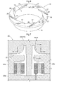
FIG. 5] FIG. 5 is a perspective view of an impeller blade. - [
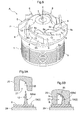
FIG. 6] FIG. 6 is a perspective view of a shroud. - [
FIG. 7] FIG. 7 is a cross-sectional view of a die device taken in a direction along a rotary shaft core of the impeller. - [
FIG. 8] FIG. 8 is a perspective view of an impeller intermediate product. - [
FIG. 9] FIGS. 9(a) and 9(b) are cross-sectional views showing a plastic deformation step. - Hereinafter, an embodiment of the present invention will be described with reference to the drawings.
FIGS. 1 and 2 show a rotor unit A of an inner-rotor brushless motor that is used in a water pump for use in a vehicle.
The rotor unit A is an integrated body including arotor 1 for the brushless motor and animpeller 2 according to the present invention that is for a water pump, is centrifugal, and is made of resin. - The
rotor 1 has ayoke 3, which is formed by stacking magnetic metal sheets, and amagnet 4, and therotor 1 is integrated with theimpeller 2 using a resin material, thus forming the rotor unit A.
This resin material can be a thermoplastic resin such as PPS (Polyphenylene Sulfide), which is a fire-retardant resin that is highly heat-resistant and rigid - The
impeller 2 is provided on one end side of therotor 1 via a connectingshaft portion 5. Theimpeller 2 rotates integrally with therotor 1, andimpeller blades 6 act on water in the water pump. - As shown in
FIG. 2 , a rotaryshaft insertion hole 7 that penetrates from therotor 1 to theimpeller 2 via the connectingshaft portion 5 is formed in a central portion of the rotor unit A. A support shaft (not shown) is inserted into the rotaryshaft insertion hole 7 from theimpeller 2 side. This support shaft is supported by two bearingportions 8 at the front and rear that are formed on the inner wall of the rotaryshaft insertion hole 7. - The
impeller 2 rotates in the direction indicated by an arrow a inFIG. 3 .
As shown inFIG. 3 as well, theimpeller 2 integrally includes a resinimpeller back plate 9, which is a circular substrate about a rotary shaft core X, and multipleresin impeller blades 6 that are provided upright along a curved shape and are spaced apart at a constant interval in the circumferential direction on one face of the impeller back plate 9 (the face on the side opposite to the rotor 1). Theimpeller back plate 9 is integrally connected to therotor 1 via the connectingshaft portion 5.
Drainage holes 10 are formed in theimpeller back plate 9. Coolant that remains at the inner circumferential-side blade portion instead of being discharged can be drained through thedrainage holes 10. - Each
impeller blade 6 extends in the circumferential direction while expanding in diameter from the rotary shaft core X side, and is provided upright such that a three-dimensional inner circumferential-side blade portion 6a and a two-dimensional outer circumferential-side blade portion 6b are continuous with each other.
The inner circumferential-side blade portion 6a is arranged so as to be located on the inner circumferential side of the impeller back plate 9 (referred to hereinafter as the inner circumferential side of the substrate) and oriented so as to extend along a curved shape having a greater curvature than that of the outer circumferential-side blade portion 6b in a direction along the rotary shaft core X, and so as to have atip side portion 6c that is bent toward the outer circumferential side of the impeller back plate 9 (downstream side in the rotation direction a) along the normal direction of the curved shape.
The outer circumferential-side blade portion 6b is arranged so as to be located on the outer circumferential side of the impeller back plate 9 (referred to hereinafter as the outer circumferential side of the substrate) and oriented so as to extend in a direction along the rotary shaft core X. - For each
impeller blade 6, with respect to the direction along the rotary shaft core X, a length (referred to hereinafter as the blade width) B of the inner circumferential-side blade portion 6a shown inFIG. 4(a) from thesubstrate 9 side to the tip side is set longer than a length (blade width) B of the outer circumferential-side blade portion 6b shown inFIG. 4(b) from thesubstrate 9 side to the tip side.
Also, as shown inFIG. 4(a) , a blade thickness T of the inner circumferential-side blade portion 6a is set so as to gradually decrease from the impeller backplate 9 side toward the tip side in the direction along the rotary shaft core X.
In other words, when thetip side portion 6c of the inner circumferential-side blade portion 6a is bent toward the downstream side in the rotation direction a, thetip side portion 6c can be easily bent into a curved shape that is bent in a continuous manner, and thus water in the water pump can be efficiently scooped in. - A
discontinuous portion 12 at which the rate of gradual decrease in the blade thickness T changes discontinuously is provided in the shape of a strip along the curved shape of the inner circumferential-side blade portion 6a (lengthwise direction of the inner circumferential-side blade portion 6a) at an intermediate position in the direction along the blade width B on ablade face 11 that faces the outer circumferential side of the substrate of the inner circumferential-side blade portion 6a (downstream side in the rotation direction a), and as shown inFIG. 5 , thetip side portion 6c of the inner circumferential-side blade portion 6a is provided upright and oriented so as to curve toward the outer circumferential side of the substrate along thediscontinuous portion 12. - A
resin shroud 13 formed in the shape of a circular ring is assembled with the outer circumferential-side blade portions 6b of theimpeller blades 6 so as to oppose the impeller backplate 9 with theimpeller blades 6 sandwiched therebetween.
As shown inFIG. 6 , theshroud 13 includes acylindrical portion 15 that forms aninlet 14, and acircular flange portion 16 to which the outer circumferential-side blade portions 6b are fixedly joined, thecylindrical portion 15 and thecircular flange portion 16 being concentric with each other. - Fitting recessed
portions 17, into which the outer circumferential-side blade portions 6b are fixedly fit, are formed spaced apart at a constant interval in the circumferential direction on an end face of thecircular flange portion 16.
The tip sides of the outer circumferential-side blade portions 6b of theimpeller blades 6 are fit into the fitting recessedportions 17 so as to be fixedly joined to them, and the inner circumferential-side blade portions 6a approach theinlet 14 from the inner side of theshroud 13. - The following describes a method for producing the
impeller 2 of the present invention, which is integrated with therotor 1.
The method for producing an impeller includes the following separate steps: a molding step of using a molding die 18, which can be mold-clamped in a direction along the rotary shaft core X of the impeller 2 as shown inFIG. 7 , to resin-mold an impeller intermediate product 19 that, as shown inFIG. 8 , integrally includes an impeller back plate 9 and multiple impeller blades 6, the impeller blades 6 each including an inner circumferential-side blade portion 6a and an outer circumferential-side blade portion 6b that are continuous with each other, the inner circumferential-side blade portion 6a being arranged so as to be located on the inner circumferential side of the substrate and oriented so as to extend in the direction along the rotary shaft core X over the entire length along the blade width B, and the outer circumferential-side blade portion 6b being arranged so as to be located on the outer circumferential side of the substrate and oriented so as to extend in the direction along the rotary shaft core X over the entire length along the blade width B; a plastic deformation step of, as shown inFIG. 9 , plastically deforming a tip side portion 6c of the inner circumferential-side blade portion 6a of the impeller intermediate product 19 so as to bend toward the outer circumferential side of the substrate; and an assembly step of assembling a shroud 13 with the impeller blades 6. -
FIG. 7 shows adie device 20 that is used for resin-molding the rotor unit A that integrally includes theimpeller 2 and therotor 1, in the molding step.
Thedie device 20 includes four molding dies, namely anupper die 20a, alower die 20b, and a pair of left and right intermediate dies 20c between theupper die 20a and thelower die 20b. - The
upper die 20a is provided so as to be able to be mold-clamped to the left and right intermediate dies 20c in the direction along the rotary shaft core X of theimpeller 2, an impeller backplate formation cavity 21 is provided between theupper die 20a and the left and right intermediate dies 20c, and theupper die 20a is provided with impeller blade formation cavities 22 that respectively correspond to theimpeller blades 6.
Accordingly, theupper die 20a corresponds to the molding die 18 that can be mold-clamped in the direction along the rotary shaft core X of theimpeller 2. - The
yoke 3 and themagnet 4 are mounted in acavity 23 formed between theupper die 20a, thelower die 20b, and the left and right intermediate dies 20c, and a resin material is injected through a gate 24 provided in theupper die 20a, thus integrally forming the rotor unit A. - The impeller blade formation cavities 22 are provided so as to form two-
dimensional impeller blades 6 oriented such that the inner circumferential-side blade portion 6a and the outer circumferential-side blade portion 6b extend on the impeller backplate 9 in the direction along the rotary shaft core X (mold-clamping direction). -
FIG. 8 shows the impellerintermediate product 19 that has been resin-molded in the molding step, and theimpeller blades 6 are integrally formed on the impeller backplate 9 so as to be two-dimensionally shaped and oriented such that the inner circumferential-side blade portion 6a and the outer circumferential-side blade portion 6b project in the direction along the rotary shaft core X on the impeller backplate 9 over the entire length along the blade width B. - The
discontinuous portion 12 at which the rate of gradual decrease in the blade thickness T changes discontinuously is formed in the shape of a strip along the curved shape of the inner circumferential-side blade portion 6a (the lengthwise direction of the inner circumferential-side blade portion 6a) on the side face of the inner circumferential-side blade portion 6a of the impellerintermediate product 19 that faces the rotation direction a. -
FIGS.9 show the plastic deformation step in which the inner circumferential-side blade portion 6a of the impellerintermediate product 19, which is placed on abase 29, is bent by being pressed by apressing die 25 under heat such that thetip side portion 6c is plastically deformed into a three-dimensional shape in an orientation of being bent toward the outer circumferential side of the substrate along thediscontinuous portion 12.
Recessedportions 27 are formed in thepressing die 25, each including apressing face 26 for deforming thetip side portion 6c of the inner circumferential-side blade portion 6a into a predetermined shape facing the downstream side in the rotation direction. - Accordingly, the inner circumferential-
side blade portion 6a of the two-dimensional impeller blade 6 that projects in the direction along the rotary shaft core X can be introduced into the recessedportion 27 so as to cause thetip side portion 6c of the inner circumferential-side blade portion 6a to be plastically deformed into a predetermined shape of being bent toward the outer circumferential side of the substrate along thediscontinuous portion 12. - In this plastic deformation step, at least the temperature of the inner circumferential-
side blade portion 6a is kept in the material deformation temperature range (210 to 220°C in the present embodiment), and then after plastic deformation into the predetermined shape, theimpeller blade 6 is rapidly cooled and hardened so as to be oriented such that the tip side of the inner circumferential-side blade portion 6a is bent toward the downstream side in the rotation direction. - As shown in FIG. 6(c), the
shroud 13, which is made of the same thermoplastic resin as the resin forming theimpeller 2, includesattachment resin projections 28 that function as attachment members and are integrally formed on the bottom faces of the fitting recessedportions 17 formed in thecircular flange portion 16, and thisshroud 13 is assembled with theimpeller blades 6 in the assembly step. - The
impeller blades 6 and theshroud 13 are joined together as shown inFIG. 1 by pressing the tip portions of the outer circumferential-side blade portions 6b into the fitting recessedportions 17 with theresin projections 28 sandwiched therebetween, and then performing ultrasonic fusion for melting theresin projections 28 with ultrasonic vibration and pressure application. -
- 1. The impeller of the present invention may integrally include impeller blades and a shroud serving as the substrate.
- 2. The impeller of the present invention may include impeller blades and a substrate that are integrally formed using a metal material.
- 3. The impeller of the present invention may be configured such that the inner circumferential-side blade portions of the impeller intermediate product, whose temperature is kept in the material deformation temperature range immediately after being resin-molded, are plastically deformed in the plastic deformation step so as to bend toward the downstream side in the rotation direction.
- 4. The impeller of the present invention may be configured such that the inner circumferential-side blade portions are provided so as to be upright and oriented such that the tip side is bent toward the inner circumferential side (upstream side in the rotation direction) of the impeller back plate (substrate) along the normal direction of the curved shape.
-
2 Impeller 6 Impeller blade 6a Inner circumferential- side blade portion 6b Outer circumferential- side blade portion 6c Tip side 9 Substrate (impeller back plate) 10 Drainage hole 11 Blade face 12 Discontinuous portion 13 Shroud 17 Fitting recessed portion 18 Molding die 19 Impeller intermediate product B Length of impeller blade from substrate side to tip side T Blade thickness X Rotary shaft core
Claims (7)
- An impeller integrally comprising:a substrate; and a plurality of impeller blades that are provided upright along a curved shape and spaced apart in a circumferential direction on one face of the substrate,wherein the impeller blades extend in the circumferential direction while expanding in diameter from a rotary shaft core side,the impeller blades are each configured by an inner circumferential-side blade portion arranged so as to be located on an inner circumferential side of the substrate and oriented so as to extend in a direction along a rotary shaft core and have a tip side that is bent, and an outer circumferential-side blade portion arranged so as to be located on an outer circumferential side of the substrate and oriented so as to extend in the direction along the rotary shaft core,with respect to the direction along the rotary shaft core, the length of the inner circumferential-side blade portion from the substrate side to the tip side is longer than the length of the outer circumferential-side blade portion from the substrate side to the tip side, andwith respect to the direction along the rotary shaft core, a blade thickness of the inner circumferential-side blade portion gradually decreases from the substrate side toward the tip side.
- An impeller integrally comprising:a substrate; and a plurality of impeller blades that are provided upright along a curved shape and spaced apart in a circumferential direction on one face of the substrate,wherein the impeller blades are each provided upright such that an inner circumferential-side blade portion and an outer circumferential-side blade portion are continuous with each other, the inner circumferential-side blade portion being arranged so as to be located on an inner circumferential side of the substrate and oriented so as to extend in a direction along a rotary shaft core and have a tip side that is bent, and the outer circumferential-side blade portion being arranged so as to be located on an outer circumferential side of the substrate and oriented so as to extend in the direction along the rotary shaft core,with respect to the direction along the rotary shaft core, the length of the inner circumferential-side blade portion from the substrate side to the tip side is longer than the length of the outer circumferential-side blade portion from the substrate side to the tip side, andwith respect to the direction along the rotary shaft core, a blade thickness of the inner circumferential-side blade portion gradually decreases from the substrate side toward the tip side.
- The impeller according to claim 1 or 2,
wherein a discontinuous portion at which a rate of gradual decrease in the blade thickness changes discontinuously is provided along the curved shape of the inner circumferential-side blade portion, and
the inner circumferential-side blade portion is provided upright and oriented so as to be bent toward at least one of the outer circumferential side of the substrate and the inner circumferential side of the substrate along the discontinuous portion. - The impeller according to any of claims 1 to 3,
wherein the substrate configures an impeller back plate, and
a shroud that is to be assembled opposing the impeller back plate with the plurality of impeller blades sandwiched therebetween is fixed to the outer circumferential-side blade portions of the impeller blades. - The impeller according to any of claims 1 to 4, wherein a drainage hole is formed in the substrate.
- The impeller according to claim 4, wherein fitting recessed portions in which the outer circumferential-side blade portions are fitted are formed in the shroud.
- A method for producing an impeller, comprising as separate steps:a molding step of using a molding die, which can be mold-clamped in a direction along a rotary shaft core of the impeller, to mold an impeller intermediate product that integrally includes a substrate and a plurality of impeller blades that are provided upright along a curved shape and spaced apart in a circumferential direction on one face of the substrate, the impeller blades each including an inner circumferential-side blade portion and an outer circumferential-side blade portion that are continuous with each other, the inner circumferential-side blade portion being arranged so as to be located on an inner circumferential side of the substrate and oriented so as to extend in the direction along the rotary shaft core, and the outer circumferential-side blade portion being arranged so as to be located on an outer circumferential side of the substrate and oriented so as to extend in the direction along the rotary shaft core; anda plastic deformation step of plastically deforming the inner circumferential-side blade portion of the impeller intermediate product so as to bend toward at least one of the outer circumferential side of the substrate and the inner circumferential side of the substrate.
Applications Claiming Priority (2)
| Application Number | Priority Date | Filing Date | Title |
|---|---|---|---|
| JP2010149413 | 2010-06-30 | ||
| PCT/JP2011/062906 WO2012002107A1 (en) | 2010-06-30 | 2011-06-06 | Impeller and method for producing same |
Publications (2)
| Publication Number | Publication Date |
|---|---|
| EP2589815A1 true EP2589815A1 (en) | 2013-05-08 |
| EP2589815A4 EP2589815A4 (en) | 2015-04-15 |
Family
ID=45401837
Family Applications (1)
| Application Number | Title | Priority Date | Filing Date |
|---|---|---|---|
| EP11800575.0A Withdrawn EP2589815A4 (en) | 2010-06-30 | 2011-06-06 | Impeller and method for producing same |
Country Status (5)
| Country | Link |
|---|---|
| US (1) | US9115589B2 (en) |
| EP (1) | EP2589815A4 (en) |
| JP (1) | JP5299727B2 (en) |
| CN (1) | CN102959249B (en) |
| WO (1) | WO2012002107A1 (en) |
Families Citing this family (17)
| Publication number | Priority date | Publication date | Assignee | Title |
|---|---|---|---|---|
| JP5998544B2 (en) * | 2012-03-13 | 2016-09-28 | アイシン精機株式会社 | Impeller manufacturing method and impeller |
| JP5847007B2 (en) * | 2012-04-23 | 2016-01-20 | 本田技研工業株式会社 | Impeller manufacturing method |
| JP2014180146A (en) * | 2013-03-15 | 2014-09-25 | Hitachi Automotive Systems Ltd | Rotor structure and electric fluid pump |
| CN103216452B (en) * | 2013-04-25 | 2016-05-11 | 常州雷利电机科技有限公司 | Draining pump |
| JP2015102002A (en) * | 2013-11-25 | 2015-06-04 | 三星電子株式会社Samsung Electronics Co.,Ltd. | Turbo-fan, and air conditioner using the same |
| CN105849418B (en) | 2013-12-27 | 2018-11-13 | 本田技研工业株式会社 | impeller |
| EP3032721B1 (en) * | 2014-12-11 | 2021-09-15 | Johnson Electric International AG | Motor, pump and cleaning apparatus |
| US10569454B2 (en) * | 2015-03-06 | 2020-02-25 | Honda Motor Co., Ltd. | Method for manufacturing impeller |
| CN104929973A (en) * | 2015-05-08 | 2015-09-23 | 江苏大学 | Multiple-stage centrifugal pump impeller matched with radial guide vane |
| US20180135643A1 (en) * | 2015-05-19 | 2018-05-17 | Hitachi, Ltd. | Centrifugal Compressor |
| JP6621194B2 (en) * | 2015-06-03 | 2019-12-18 | 三星電子株式会社Samsung Electronics Co.,Ltd. | Turbofan and blower using the turbofan |
| US10001133B2 (en) * | 2015-10-02 | 2018-06-19 | Sundyne, Llc | Low-cavitation impeller and pump |
| JP6297529B2 (en) * | 2015-10-22 | 2018-03-20 | ミネベアミツミ株式会社 | Impeller, method for manufacturing the impeller, and centrifugal fan including the impeller |
| CN114207289A (en) * | 2018-11-08 | 2022-03-18 | 吉普工业(澳大利亚)集团有限公司 | Pump assembly |
| ES2953936T3 (en) * | 2019-12-13 | 2023-11-17 | Dab Pumps Spa | Impeller for centrifugal pump, particularly for a pump with a recessed impeller, and pump with said impeller |
| TWI745927B (en) * | 2020-04-13 | 2021-11-11 | 宏碁股份有限公司 | Centrifugal heat dissipation fan |
| CN114013061A (en) * | 2021-11-03 | 2022-02-08 | 深圳市希伯伦科技有限公司 | Waist-hung type fan blade multi-position integrated injection molding device and processing method |
Family Cites Families (10)
| Publication number | Priority date | Publication date | Assignee | Title |
|---|---|---|---|---|
| CA1183675A (en) | 1980-12-19 | 1985-03-12 | Isao Miki | Method for producing profiled product having fins |
| JPS58119998A (en) * | 1982-01-12 | 1983-07-16 | Mitsubishi Heavy Ind Ltd | Turbine wheel of compressor and its manufacture |
| JPS58128243A (en) * | 1982-01-27 | 1983-07-30 | Nippon Light Metal Co Ltd | Production of impeller |
| JPS59120338A (en) | 1982-12-28 | 1984-07-11 | Nippon Light Metal Co Ltd | Impeller manufacturing method |
| US4708593A (en) * | 1986-02-28 | 1987-11-24 | Robinson Industries, Inc. | Surgeless combustion air blower |
| JP2666490B2 (en) | 1989-10-20 | 1997-10-22 | 松下電器産業株式会社 | Electric blower |
| JP3617095B2 (en) | 1995-01-18 | 2005-02-02 | 松下電器産業株式会社 | Electric blower |
| JP4187402B2 (en) * | 2000-12-19 | 2008-11-26 | 株式会社林技術研究所 | Terminal bending method |
| JP4663259B2 (en) | 2004-06-18 | 2011-04-06 | 日立アプライアンス株式会社 | Blower and vacuum cleaner |
| JP5223250B2 (en) | 2006-12-14 | 2013-06-26 | パナソニック株式会社 | Centrifugal impeller and centrifugal blower |
-
2011
- 2011-06-06 WO PCT/JP2011/062906 patent/WO2012002107A1/en not_active Ceased
- 2011-06-06 EP EP11800575.0A patent/EP2589815A4/en not_active Withdrawn
- 2011-06-06 JP JP2012522537A patent/JP5299727B2/en not_active Expired - Fee Related
- 2011-06-06 CN CN201180030523.5A patent/CN102959249B/en not_active Expired - Fee Related
- 2011-06-06 US US13/700,928 patent/US9115589B2/en not_active Expired - Fee Related
Also Published As
| Publication number | Publication date |
|---|---|
| CN102959249B (en) | 2015-09-23 |
| JPWO2012002107A1 (en) | 2013-08-22 |
| WO2012002107A1 (en) | 2012-01-05 |
| US9115589B2 (en) | 2015-08-25 |
| US20130071247A1 (en) | 2013-03-21 |
| EP2589815A4 (en) | 2015-04-15 |
| JP5299727B2 (en) | 2013-09-25 |
| CN102959249A (en) | 2013-03-06 |
Similar Documents
| Publication | Publication Date | Title |
|---|---|---|
| US9115589B2 (en) | Impeller and method for producing same | |
| CN105849418B (en) | impeller | |
| CN107046338B (en) | Rotor for electric motor and method of manufacturing rotor for electric motor | |
| JP6424613B2 (en) | Method of manufacturing core of electric rotating machine | |
| CN1848614B (en) | Magnet embedded motor, rotor unit and producing method of rotor unit | |
| EP3070337B1 (en) | Fan impeller and method for manufacturing the same | |
| CN100552231C (en) | Impeller of multiblade blower and method for manufacturing the same | |
| KR102069575B1 (en) | A Manufacturing Method for Impeller | |
| CN104798289A (en) | Rotor of an electric motor and method for producing the rotor | |
| CN201241862Y (en) | Combined Miniature Axial Fan | |
| CN107428049B (en) | Method for manufacturing impeller | |
| JP2018017167A (en) | Impeller and motor | |
| JP5303120B2 (en) | Impeller | |
| JP2012154339A (en) | Method of manufacturing impeller | |
| CN102062111B (en) | Composite structure of radiator fan and molding method thereof | |
| KR20080045564A (en) | Turbo fan and its manufacturing method | |
| JP2667748B2 (en) | Multi-wing impeller | |
| JP5533060B2 (en) | Turbocharger | |
| JP2000213493A (en) | Impeller and manufacture thereof | |
| JP2017129015A (en) | Resin impeller | |
| WO2013042471A1 (en) | Seal plate with spacer and manufacturing method therefor | |
| JP2005240557A (en) | Method of manufacturing impeller of water pump for cooling automobile engine | |
| CN118582418A (en) | Impeller, air supply device, mold and impeller manufacturing method | |
| CN118582417A (en) | Impeller, air supply device, mold and impeller manufacturing method | |
| JP2014124684A (en) | Press mold |
Legal Events
| Date | Code | Title | Description |
|---|---|---|---|
| PUAI | Public reference made under article 153(3) epc to a published international application that has entered the european phase |
Free format text: ORIGINAL CODE: 0009012 |
|
| 17P | Request for examination filed |
Effective date: 20121214 |
|
| AK | Designated contracting states |
Kind code of ref document: A1 Designated state(s): AL AT BE BG CH CY CZ DE DK EE ES FI FR GB GR HR HU IE IS IT LI LT LU LV MC MK MT NL NO PL PT RO RS SE SI SK SM TR |
|
| DAX | Request for extension of the european patent (deleted) | ||
| RA4 | Supplementary search report drawn up and despatched (corrected) |
Effective date: 20150312 |
|
| RIC1 | Information provided on ipc code assigned before grant |
Ipc: F04D 29/24 20060101ALI20150306BHEP Ipc: B29C 67/00 20060101ALI20150306BHEP Ipc: F04D 29/22 20060101ALI20150306BHEP Ipc: F04D 29/30 20060101AFI20150306BHEP Ipc: B29C 53/02 20060101ALI20150306BHEP Ipc: F04D 29/28 20060101ALI20150306BHEP |
|
| GRAP | Despatch of communication of intention to grant a patent |
Free format text: ORIGINAL CODE: EPIDOSNIGR1 |
|
| RIC1 | Information provided on ipc code assigned before grant |
Ipc: F04D 29/24 20060101ALI20171204BHEP Ipc: B29L 31/00 20060101ALN20171204BHEP Ipc: B29C 67/00 20170101ALI20171204BHEP Ipc: F04D 29/22 20060101ALI20171204BHEP Ipc: F04D 29/28 20060101ALI20171204BHEP Ipc: B29C 53/02 20060101ALI20171204BHEP Ipc: F04D 29/30 20060101AFI20171204BHEP Ipc: F01D 5/14 20060101ALI20171204BHEP Ipc: B29L 31/08 20060101ALN20171204BHEP Ipc: F04D 13/06 20060101ALI20171204BHEP |
|
| INTG | Intention to grant announced |
Effective date: 20171218 |
|
| STAA | Information on the status of an ep patent application or granted ep patent |
Free format text: STATUS: THE APPLICATION IS DEEMED TO BE WITHDRAWN |
|
| 18D | Application deemed to be withdrawn |
Effective date: 20180501 |