EP2589702A1 - Headbox for a fiber web machine - Google Patents
Headbox for a fiber web machine Download PDFInfo
- Publication number
- EP2589702A1 EP2589702A1 EP20120185036 EP12185036A EP2589702A1 EP 2589702 A1 EP2589702 A1 EP 2589702A1 EP 20120185036 EP20120185036 EP 20120185036 EP 12185036 A EP12185036 A EP 12185036A EP 2589702 A1 EP2589702 A1 EP 2589702A1
- Authority
- EP
- European Patent Office
- Prior art keywords
- pipe
- headbox
- pipes
- flow
- intermediate pipe
- Prior art date
- Legal status (The legal status is an assumption and is not a legal conclusion. Google has not performed a legal analysis and makes no representation as to the accuracy of the status listed.)
- Granted
Links
Images


Classifications
-
- D—TEXTILES; PAPER
- D21—PAPER-MAKING; PRODUCTION OF CELLULOSE
- D21F—PAPER-MAKING MACHINES; METHODS OF PRODUCING PAPER THEREON
- D21F1/00—Wet end of machines for making continuous webs of paper
- D21F1/02—Head boxes of Fourdrinier machines
- D21F1/026—Details of the turbulence section
-
- D—TEXTILES; PAPER
- D21—PAPER-MAKING; PRODUCTION OF CELLULOSE
- D21F—PAPER-MAKING MACHINES; METHODS OF PRODUCING PAPER THEREON
- D21F1/00—Wet end of machines for making continuous webs of paper
- D21F1/02—Head boxes of Fourdrinier machines
-
- D—TEXTILES; PAPER
- D21—PAPER-MAKING; PRODUCTION OF CELLULOSE
- D21F—PAPER-MAKING MACHINES; METHODS OF PRODUCING PAPER THEREON
- D21F1/00—Wet end of machines for making continuous webs of paper
- D21F1/02—Head boxes of Fourdrinier machines
- D21F1/024—Details of the feed chamber
-
- D—TEXTILES; PAPER
- D21—PAPER-MAKING; PRODUCTION OF CELLULOSE
- D21F—PAPER-MAKING MACHINES; METHODS OF PRODUCING PAPER THEREON
- D21F1/00—Wet end of machines for making continuous webs of paper
- D21F1/06—Regulating pulp flow
Definitions
- the invention relates to a headbox for a fiber web machine, the headbox including a turbulence generator with flow pipes to which a manifold is arranged to be connected using intermediate pipes.
- the headbox of a fiber web machine is supplied with web forming stock from a manifold or a similar delivery pipe.
- a multi-layer headbox can have several, such as 3 to 5, manifolds.
- the manifold can be connected to the headbox with a multitude of flexible, elastic intermediate pipes, for example.
- the web forming stock is supplied to the headbox through these in a desired manner, across its main width.
- a known headbox construction includes a number of successive subassemblies. Starting from the inlet side, these typically include a manifold, manifold tubes, an equalizing chamber, a turbulence generator, a slice channel, and a slice opening, from which the web forming stock is discharged to the forming section. Since each subassembly is massive and requires high precision manufacturing, the manufacturing of a headbox is capital-intensive. In addition, each subassembly increases the headbox length in the machine direction, which affects the total machine investment cost.
- the object of this invention is to provide a headbox for a fiber web machine enabling the connection of the manifold to the headbox internal structures located in a confined space.
- the characteristic features of the headbox according to the invention are set forth in claim 1.
- the intermediate pipes connecting the manifold and the flow pipes of the turbulence generator are arranged to extend within the turbulence generator flow pipe and these intermediate pipes are fastened to the inner surface of the flow pipe.
- the intermediate pipes By taking the intermediate pipes as far as this within the headbox, the need of constructing subassemblies is avoided and thereby the price of the headbox is reduced.
- thermal expansion of the headbox can be better controlled.
- the intermediate pipe instead of fixed headbox constructions, can take up any potential thermal expansion.
- the intermediate pipe is also easy to replace, if necessary.
- a step is arranged to form at the boundary between the intermediate pipe and the turbulence generator flow pipe.
- the flow pipe can be made of a straight pipe.
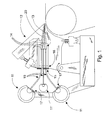
- Figures 1 to 3 are sectional side views of an embodiment of a headbox 12 for a fiber web machine.
- the headbox 12 includes, in a manner known as such, a turbulence generator 13 equipped with flow pipes 14.
- At least one manifold 11, 11', for example, separate from the headbox 12, is arranged to be connected to the flow pipes 14 with intermediate pipes 10.
- the manifold 11, 11' is typically a tubular manifold 11 for a stock suspension, for example, but it can also be a manifold 11' for dilution water, for example, or another type of stock suspension delivery system, such as a so-called octopus manifold (not shown).
- FIG 1 two stock suspension manifolds 11 and one dilution water manifold 11' are connected to the headbox 12 with intermediate pipes 10 to provide a water layer.
- the intermediate pipes 10 are used to connect two manifolds 11 to the headbox 12.
- the manifold 19 for the dilution water used for the fiber web basis weight profile is located near the second manifold 11, from which dilution water is supplied via a dilution water element to an intermediate pipe 10 shared with the manifold 11.
- the intermediate pipes 10 are used to connect two manifolds 11 to the headbox 12.
- an intermediate pipe 10 according to the invention is particularly suitable for applications using multi-layer headboxes 12; however, it can also be applied in single-layer headboxes.
- Figure 4 shows an example of connecting the intermediate pipe 10 and the flow pipe 14 of the turbulence generator 13 to each other.
- the length and diameter of the intermediate pipe 10 are dimensioned in such a way that the intermediate pipe 10 can be fastened to the flow pipe 14 of the turbulence generator 13 within the headbox 12.
- the intermediate pipe 10 outer surface is fastened to the inner surface of the flow pipe 14.
- the flow pipe 14 can have, in a manner known as such, at least two successive cross-section profiles allowing the connection of the intermediate pipe 10 to the pipe section on the inlet side.
- the intermediate pipe 10 can be arranged within the flow pipe 14 for a distance D. Then a step 21 ( Figure 4 ) is formed at the boundary between the intermediate pipe 10 and the flow pipe 14; this step can serve to generate turbulence.
- the flow pipe 14 can even be made of a straight pipe, which makes it inexpensive to manufacture.
- the intermediate pipe 10 is made of plastic, it can be made smooth on the outer surface to be easy to push within the flow pipe 14.
- Arranging the intermediate pipe 10 within the flow pipe 14 is advantageous because the flow pipes 14 of the turbulence generator 13 are relatively densely spaced.
- the construction of the flow pipe 14 becomes advantageous when it can be made of a straight pipe whose end located on the side of the slice channel 20 is simply made to a rectangular or another similar form.
- the intermediate pipe 10 is also equipped with a sealing arrangement 18 for sealing the joint between the intermediate pipe 10 and the flow pipe 14.
- An example of the sealing arrangement may be an O-ring 18, for which at least one groove is arranged at the end of the intermediate pipe 10, on its outer surface, for a sealing ring 18.
- connection arrangement 15 is adapted in the intermediate pipe 10 for connecting it to the constructions 16 on the inlet side of the headbox 12.
- the connection arrangement 15 can be formed, for example, by locking rings formed on the outer surface of the intermediate pipe 10 from which it can be connected to the force plate 16 of the headbox 12.
- the intermediate pipe 10 is also provided with a connection arrangement 17 for connecting it to the manifold 11.
- This can also be implemented in the same way as the connection to the constructions of the headbox 12, using a small reduction sleeve, for example.
- the intermediate pipe 10 can also vary its length during thermal expansion. Across this distance, the intermediate pipe 10 can have a curved shape, the curvature serving to take up thermal expansion.
- the intermediate pipe 10 can be pre-bent in the longitudinal direction, which facilitates the control of thermal expansion between the manifold 11 and the headbox 12. This assists in its installation between the headbox 12 and the manifold 11, particularly if they are located at different levels in the vertical direction.
- the material of the intermediate pipe 10 can be plastic, for example, such as polyamide, PE or POM, generally industrial plastic, and an example of its manufacturing method can be extrusion.
- the intermediate pipe 10 can have a constant inner diameter and outer design.
- the intermediate pipe 10 can be an integral component. Since an intermediate pipe 10 made of plastic can resist slight bending, the pipe 10 is also suitable for headboxes 12 in which the tilt angle is adjustable. A flexible intermediate pipe 10 also enables free tilting of the headbox 12 while the manifolds 11 are kept in place.
- At least one local change in the cross-section can be arranged in the intermediate pipe 10. This creates a flow change in a desired place in the intermediate pipe 10, which is advantageous for the turbulence phenomenon.
- a fiber web machine refers to paper, board and tissue machines as well as pulp drying machines.
- the invention relates to a headbox for a fiber web machine including a turbulence generator (13) equipped with flow pipes (14) to which at least one manifold (11, 11') is arranged to be connected using intermediate pipes (10). At least part of the intermediate pipes are arranged to extend within the flow pipe of the turbulence generator.
Landscapes
- Paper (AREA)
Abstract
Description
- The invention relates to a headbox for a fiber web machine, the headbox including a turbulence generator with flow pipes to which a manifold is arranged to be connected using intermediate pipes.
- The headbox of a fiber web machine is supplied with web forming stock from a manifold or a similar delivery pipe. A multi-layer headbox can have several, such as 3 to 5, manifolds. The manifold can be connected to the headbox with a multitude of flexible, elastic intermediate pipes, for example. The web forming stock is supplied to the headbox through these in a desired manner, across its main width.
- A prior art solution is proposed in international patent application publication
WO 01/38775 A1 - A known headbox construction includes a number of successive subassemblies. Starting from the inlet side, these typically include a manifold, manifold tubes, an equalizing chamber, a turbulence generator, a slice channel, and a slice opening, from which the web forming stock is discharged to the forming section. Since each subassembly is massive and requires high precision manufacturing, the manufacturing of a headbox is capital-intensive. In addition, each subassembly increases the headbox length in the machine direction, which affects the total machine investment cost.
- The object of this invention is to provide a headbox for a fiber web machine enabling the connection of the manifold to the headbox internal structures located in a confined space. The characteristic features of the headbox according to the invention are set forth in
claim 1. - In the invention, at least part of the intermediate pipes connecting the manifold and the flow pipes of the turbulence generator are arranged to extend within the turbulence generator flow pipe and these intermediate pipes are fastened to the inner surface of the flow pipe. The invention removes the need of various fitting elements and makes it possible to create the connection in spite of the confined headbox internal space. Also, with the invention, it is not necessary to compromise over the spacing of the turbulence generator flow pipes.
- By taking the intermediate pipes as far as this within the headbox, the need of constructing subassemblies is avoided and thereby the price of the headbox is reduced. Using an intermediate pipe, thermal expansion of the headbox can be better controlled. The intermediate pipe, instead of fixed headbox constructions, can take up any potential thermal expansion. The intermediate pipe is also easy to replace, if necessary.
- According to another embodiment, a step is arranged to form at the boundary between the intermediate pipe and the turbulence generator flow pipe. Thus the flow pipe can be made of a straight pipe. Other additional advantages achieved with the invention become evident from the specification while the characteristic features are set forth in the appended claims.
- The invention, which is not limited to the embodiment set forth below, is described in more detail by making reference to the enclosed drawings, in which:
- Figure 1
- is a sectional side view of a first example of a headbox provided with intermediate pipes;
- Figure 2
- is a sectional side view of a second example of a headbox provided with intermediate pipes;
- Figure 3
- is a sectional side view of a third example of a headbox provided with intermediate pipes; and
- Figure 4
- shows an example of connecting the intermediate pipes and the turbulence generator flow pipe to each other.
-
Figures 1 to 3 are sectional side views of an embodiment of aheadbox 12 for a fiber web machine. Theheadbox 12 includes, in a manner known as such, aturbulence generator 13 equipped withflow pipes 14. At least onemanifold 11, 11', for example, separate from theheadbox 12, is arranged to be connected to theflow pipes 14 withintermediate pipes 10. Themanifold 11, 11' is typically atubular manifold 11 for a stock suspension, for example, but it can also be a manifold 11' for dilution water, for example, or another type of stock suspension delivery system, such as a so-called octopus manifold (not shown). - In
Figure 1 , two stock suspension manifolds 11 and one dilution water manifold 11' are connected to theheadbox 12 withintermediate pipes 10 to provide a water layer. InFigure 2 , theintermediate pipes 10 are used to connect twomanifolds 11 to theheadbox 12. Themanifold 19 for the dilution water used for the fiber web basis weight profile is located near thesecond manifold 11, from which dilution water is supplied via a dilution water element to anintermediate pipe 10 shared with themanifold 11. InFigure 3 , theintermediate pipes 10 are used to connect twomanifolds 11 to theheadbox 12. As can be clearly seen fromFigures 1 to 3 , anintermediate pipe 10 according to the invention is particularly suitable for applications usingmulti-layer headboxes 12; however, it can also be applied in single-layer headboxes. -
Figure 4 shows an example of connecting theintermediate pipe 10 and theflow pipe 14 of theturbulence generator 13 to each other. As was shown inFigures 1 to 3 , the length and diameter of theintermediate pipe 10 are dimensioned in such a way that theintermediate pipe 10 can be fastened to theflow pipe 14 of theturbulence generator 13 within theheadbox 12. Theintermediate pipe 10 outer surface is fastened to the inner surface of theflow pipe 14. Thus, at least part of theintermediate pipes 10 are arranged to extend within theflow pipe 14 of theturbulence generator 13. Theflow pipe 14 can have, in a manner known as such, at least two successive cross-section profiles allowing the connection of theintermediate pipe 10 to the pipe section on the inlet side. By connecting theintermediate pipe 10 directly to theflow pipe 14, theheadbox 12 no longer needs an equalizing chamber or manifold tubes. - The
intermediate pipe 10 can be arranged within theflow pipe 14 for a distance D. Then a step 21 (Figure 4 ) is formed at the boundary between theintermediate pipe 10 and theflow pipe 14; this step can serve to generate turbulence. Theflow pipe 14 can even be made of a straight pipe, which makes it inexpensive to manufacture. For example, if theintermediate pipe 10 is made of plastic, it can be made smooth on the outer surface to be easy to push within theflow pipe 14. Arranging theintermediate pipe 10 within theflow pipe 14 is advantageous because theflow pipes 14 of theturbulence generator 13 are relatively densely spaced. In addition, the construction of theflow pipe 14 becomes advantageous when it can be made of a straight pipe whose end located on the side of theslice channel 20 is simply made to a rectangular or another similar form. - Fitting the
intermediate pipe 10 within theflow pipe 14 is arranged to allow for it a slight movement relative to theflow pipe 14. Thus theintermediate pipe 10 can take up length changes due to temperature variations. Theintermediate pipe 10 is also equipped with asealing arrangement 18 for sealing the joint between theintermediate pipe 10 and theflow pipe 14. An example of the sealing arrangement may be an O-ring 18, for which at least one groove is arranged at the end of theintermediate pipe 10, on its outer surface, for asealing ring 18. - As shown in
Figures 1 to 3 , aconnection arrangement 15 is adapted in theintermediate pipe 10 for connecting it to theconstructions 16 on the inlet side of theheadbox 12. According to an embodiment, theconnection arrangement 15 can be formed, for example, by locking rings formed on the outer surface of theintermediate pipe 10 from which it can be connected to theforce plate 16 of theheadbox 12. - Correspondingly, the
intermediate pipe 10 is also provided with aconnection arrangement 17 for connecting it to themanifold 11. This can also be implemented in the same way as the connection to the constructions of theheadbox 12, using a small reduction sleeve, for example. Between theheadbox 12 and themanifold 11, theintermediate pipe 10 can also vary its length during thermal expansion. Across this distance, theintermediate pipe 10 can have a curved shape, the curvature serving to take up thermal expansion. - The
intermediate pipe 10 can be pre-bent in the longitudinal direction, which facilitates the control of thermal expansion between themanifold 11 and theheadbox 12. This assists in its installation between theheadbox 12 and themanifold 11, particularly if they are located at different levels in the vertical direction. The material of theintermediate pipe 10 can be plastic, for example, such as polyamide, PE or POM, generally industrial plastic, and an example of its manufacturing method can be extrusion. - The
intermediate pipe 10 can have a constant inner diameter and outer design. For example, by casting from plastic, theintermediate pipe 10 can be an integral component. Since anintermediate pipe 10 made of plastic can resist slight bending, thepipe 10 is also suitable forheadboxes 12 in which the tilt angle is adjustable. A flexibleintermediate pipe 10 also enables free tilting of theheadbox 12 while themanifolds 11 are kept in place. - At least one local change in the cross-section can be arranged in the
intermediate pipe 10. This creates a flow change in a desired place in theintermediate pipe 10, which is advantageous for the turbulence phenomenon. - In the context of the invention, a fiber web machine refers to paper, board and tissue machines as well as pulp drying machines.
- It is understood that the above description and the figures related thereto are only intended for illustrating the present invention. The invention is thus not limited only to the embodiments described above or those set forth in the claims, but many different variations and modifications of the invention, which are possible within the inventional idea specified in the appended claims, will be apparent for one skilled in the art.
- The invention relates to a headbox for a fiber web machine including a turbulence generator (13) equipped with flow pipes (14) to which at least one manifold (11, 11') is arranged to be connected using intermediate pipes (10). At least part of the intermediate pipes are arranged to extend within the flow pipe of the turbulence generator.
Claims (10)
- A headbox for a fiber web machine including a turbulence generator (13) equipped with flow pipes (14) to which at least one manifold (11, 11') is arranged to be connected using intermediate pipes (10), characterized in that at least part of the intermediate pipes (10) are arranged to extend within the flow pipe (14) of the turbulence generator (13) and these intermediate pipes (10) are fastened to the inner surface of the flow pipe (14).
- A headbox according to claim 1, characterized in that the intermediate pipe (10) is an integral component.
- A headbox according to claim 1 or 2, characterized in that a connection arrangement (15) is arranged in the intermediate pipe (10) for connecting it to the constructions (16) on the inlet side of the headbox (12).
- A headbox according to any of claims 1 to 3, characterized in that a connection arrangement (17) is arranged in the intermediate pipe (10) for connecting it to the manifold (11).
- A headbox according to any of claims 1 to 4, characterized in that the fitting of the intermediate pipe (10) to the flow pipe (14) is arranged to allow for it a slight movement relative to the flow pipe (14).
- A headbox according to any of claims 1 to 5, characterized in that the intermediate pipe (10) is equipped with a sealing arrangement (18) for sealing the joint between the intermediate pipe (10) and the flow pipe (14).
- A headbox according to any of claims 1 to 6, characterized in that at least one local change in the cross-section is arranged in the intermediate pipe (10).
- A headbox according to any of claims 1 to 7, characterized in that the material of the intermediate pipe (10) is plastic.
- A headbox according to any of claims 1 to 8, characterized in that the intermediate pipe (10) is pre-bent in its longitudinal direction.
- A headbox according to any of claims 1 to 9, characterized in that a step (21) is arranged to form at the boundary between the intermediate pipe (10) and the flow pipe (14) and the flow pipe (14) is made of a straight pipe.
Applications Claiming Priority (1)
| Application Number | Priority Date | Filing Date | Title |
|---|---|---|---|
| FI20116079A FI125215B (en) | 2011-11-02 | 2011-11-02 | Inlet box for a fiber web machine |
Publications (2)
| Publication Number | Publication Date |
|---|---|
| EP2589702A1 true EP2589702A1 (en) | 2013-05-08 |
| EP2589702B1 EP2589702B1 (en) | 2016-05-18 |
Family
ID=46851887
Family Applications (1)
| Application Number | Title | Priority Date | Filing Date |
|---|---|---|---|
| EP12185036.6A Active EP2589702B1 (en) | 2011-11-02 | 2012-09-19 | Assembly for a fiber web machine comprising a headbox |
Country Status (3)
| Country | Link |
|---|---|
| EP (1) | EP2589702B1 (en) |
| CN (1) | CN103088690B (en) |
| FI (1) | FI125215B (en) |
Families Citing this family (2)
| Publication number | Priority date | Publication date | Assignee | Title |
|---|---|---|---|---|
| EP3012370B1 (en) * | 2014-10-22 | 2018-08-15 | Valmet Technologies, Inc. | Waste sludge recycling apparatus and method for recycling of waste sludge |
| EP4158096A4 (en) | 2020-05-29 | 2024-06-12 | Kimberly-Clark Worldwide, Inc. | HEADBOX FOR MANUFACTURING A SUBSTRATE |
Citations (4)
| Publication number | Priority date | Publication date | Assignee | Title |
|---|---|---|---|---|
| DE2726709B1 (en) * | 1977-05-23 | 1979-01-04 | Escher Wyss Gmbh | Headbox of a paper machine |
| WO1998046823A1 (en) * | 1997-04-14 | 1998-10-22 | Vaahto Oy | Control flow system (method and device) in the headbox of a paper machine |
| WO2001038775A1 (en) | 1999-11-26 | 2001-05-31 | Metso Paper Karlstad Aktiebolag | Coupling arrangement comprising connection devices for conduits or the like |
| WO2008105714A1 (en) * | 2007-03-01 | 2008-09-04 | Metso Paper Karlstad Ab | Structural element for a functional member of a headbox in a web-manufacturing machine, functional member and headbox made thereof, and associated methods |
Family Cites Families (4)
| Publication number | Priority date | Publication date | Assignee | Title |
|---|---|---|---|---|
| CN1011722B (en) * | 1989-03-13 | 1991-02-20 | 化学工业部化工矿山设计研究院 | Underground discharge of old brine after mining and processing of salt deposits |
| FI84921C (en) * | 1989-12-22 | 1992-02-10 | Ahlstroem Valmet | EN ELLER FLERSKIKTS INLOPPSLAODA MED UTVIDGAD REGLERZON AV GENOMLOPPSVOLYM. |
| FI100894B (en) * | 1993-07-01 | 1998-03-13 | Valmet Paper Machinery Inc | Method and apparatus for controlling the inlet box |
| DE19942047A1 (en) * | 1999-08-10 | 2001-02-15 | Voith Paper Patent Gmbh | Stock inlet turbulence generator, has insert for at least one turbulence tube with mechanism to vary its cross section by structured movements in wide setting range with high mechanical stability |
-
2011
- 2011-11-02 FI FI20116079A patent/FI125215B/en active IP Right Grant
-
2012
- 2012-09-19 EP EP12185036.6A patent/EP2589702B1/en active Active
- 2012-10-30 CN CN201210425399.9A patent/CN103088690B/en active Active
Patent Citations (4)
| Publication number | Priority date | Publication date | Assignee | Title |
|---|---|---|---|---|
| DE2726709B1 (en) * | 1977-05-23 | 1979-01-04 | Escher Wyss Gmbh | Headbox of a paper machine |
| WO1998046823A1 (en) * | 1997-04-14 | 1998-10-22 | Vaahto Oy | Control flow system (method and device) in the headbox of a paper machine |
| WO2001038775A1 (en) | 1999-11-26 | 2001-05-31 | Metso Paper Karlstad Aktiebolag | Coupling arrangement comprising connection devices for conduits or the like |
| WO2008105714A1 (en) * | 2007-03-01 | 2008-09-04 | Metso Paper Karlstad Ab | Structural element for a functional member of a headbox in a web-manufacturing machine, functional member and headbox made thereof, and associated methods |
Also Published As
| Publication number | Publication date |
|---|---|
| CN103088690B (en) | 2016-06-22 |
| FI125215B (en) | 2015-07-15 |
| CN103088690A (en) | 2013-05-08 |
| FI20116079L (en) | 2013-05-03 |
| EP2589702B1 (en) | 2016-05-18 |
Similar Documents
| Publication | Publication Date | Title |
|---|---|---|
| US8221590B2 (en) | Headbox for a machine for producing a fibrous web | |
| US8986317B2 (en) | Instrument and method for making the same | |
| ITTO20080126U1 (en) | DUCT FOR FLUIDS. | |
| EP2589702B1 (en) | Assembly for a fiber web machine comprising a headbox | |
| US20120168105A1 (en) | Headbox for a machine for producing a fibrous web | |
| EP2028469B1 (en) | Pressure gauge device | |
| WO2011095252A1 (en) | Headbox for a machine for producing a fibrous material web | |
| US6846386B2 (en) | Method of ensuring flatness of a vane in a headbox by means of a mounting arrangement, headbox with such a mounting arrangement, a mounting arrangement and vane therefor | |
| CN102021753B (en) | Nozzle strip for a textile processing machine | |
| US8889014B2 (en) | Assembly with multiple hydrocyclones, method for assembling multiple hydrocyclones and support structure for multiple hydrocyclones | |
| CN108014933A (en) | Fluid distributor body and bathroom shower | |
| FI105407B (en) | Inlet box in a papermaking machine or cardboard making machine | |
| US5000227A (en) | Pressurized fluid carrier conduit connection | |
| EP2992138B1 (en) | Pneumatically-expandable cable track for scanning head of paper machine or other system | |
| DE102009051503A1 (en) | Molded hose useful for fuel applications, comprises a barrier layer, and an elastomeric layer, which is arranged radially outside to the barrier layer, where the molded hose is crosslinked in a three-dimensional curved condition | |
| US6146501A (en) | Cross-machine direction stiffened dividers for a papermaking headbox | |
| US6352616B1 (en) | Jointless lamellae for a headbox | |
| FI101726B (en) | Control flow system (method and device) in a paper machine in a drawer | |
| FI121795B (en) | Headbox Turbine Generator Sleeve | |
| US20220221088A1 (en) | Fluid line having a wave form portion | |
| US6736938B2 (en) | Headbox and arrangement and method for mounting a vane thereof | |
| EP4528025A1 (en) | Dilution element for headbox of fibre web machine, and headbox of fibre web machine | |
| WO1997033038A1 (en) | An arrangement for feeding stock to a headbox in a papermaking machine | |
| CN102947504A (en) | Headbox for a machine for producing a fibre-material web | |
| FI115648B (en) | Vane for headbox of paper, board or tissue machine, has pivot member element with longitudinally extending positioning hole(s) which is occupied by anchoring element which also occupies vane hole |
Legal Events
| Date | Code | Title | Description |
|---|---|---|---|
| PUAI | Public reference made under article 153(3) epc to a published international application that has entered the european phase |
Free format text: ORIGINAL CODE: 0009012 |
|
| 17P | Request for examination filed |
Effective date: 20120919 |
|
| AK | Designated contracting states |
Kind code of ref document: A1 Designated state(s): AL AT BE BG CH CY CZ DE DK EE ES FI FR GB GR HR HU IE IS IT LI LT LU LV MC MK MT NL NO PL PT RO RS SE SI SK SM TR |
|
| AX | Request for extension of the european patent |
Extension state: BA ME |
|
| RAP1 | Party data changed (applicant data changed or rights of an application transferred) |
Owner name: VALMET TECHNOLOGIES, INC. |
|
| 17Q | First examination report despatched |
Effective date: 20140801 |
|
| GRAP | Despatch of communication of intention to grant a patent |
Free format text: ORIGINAL CODE: EPIDOSNIGR1 |
|
| INTG | Intention to grant announced |
Effective date: 20151204 |
|
| GRAS | Grant fee paid |
Free format text: ORIGINAL CODE: EPIDOSNIGR3 |
|
| GRAA | (expected) grant |
Free format text: ORIGINAL CODE: 0009210 |
|
| AK | Designated contracting states |
Kind code of ref document: B1 Designated state(s): AL AT BE BG CH CY CZ DE DK EE ES FI FR GB GR HR HU IE IS IT LI LT LU LV MC MK MT NL NO PL PT RO RS SE SI SK SM TR |
|
| REG | Reference to a national code |
Ref country code: GB Ref legal event code: FG4D |
|
| REG | Reference to a national code |
Ref country code: CH Ref legal event code: EP |
|
| REG | Reference to a national code |
Ref country code: IE Ref legal event code: FG4D Ref country code: AT Ref legal event code: REF Ref document number: 800582 Country of ref document: AT Kind code of ref document: T Effective date: 20160615 |
|
| REG | Reference to a national code |
Ref country code: DE Ref legal event code: R096 Ref document number: 602012018450 Country of ref document: DE |
|
| REG | Reference to a national code |
Ref country code: NL Ref legal event code: MP Effective date: 20160518 |
|
| REG | Reference to a national code |
Ref country code: LT Ref legal event code: MG4D |
|
| PG25 | Lapsed in a contracting state [announced via postgrant information from national office to epo] |
Ref country code: LT Free format text: LAPSE BECAUSE OF FAILURE TO SUBMIT A TRANSLATION OF THE DESCRIPTION OR TO PAY THE FEE WITHIN THE PRESCRIBED TIME-LIMIT Effective date: 20160518 Ref country code: NL Free format text: LAPSE BECAUSE OF FAILURE TO SUBMIT A TRANSLATION OF THE DESCRIPTION OR TO PAY THE FEE WITHIN THE PRESCRIBED TIME-LIMIT Effective date: 20160518 Ref country code: NO Free format text: LAPSE BECAUSE OF FAILURE TO SUBMIT A TRANSLATION OF THE DESCRIPTION OR TO PAY THE FEE WITHIN THE PRESCRIBED TIME-LIMIT Effective date: 20160818 Ref country code: FI Free format text: LAPSE BECAUSE OF FAILURE TO SUBMIT A TRANSLATION OF THE DESCRIPTION OR TO PAY THE FEE WITHIN THE PRESCRIBED TIME-LIMIT Effective date: 20160518 |
|
| PG25 | Lapsed in a contracting state [announced via postgrant information from national office to epo] |
Ref country code: LV Free format text: LAPSE BECAUSE OF FAILURE TO SUBMIT A TRANSLATION OF THE DESCRIPTION OR TO PAY THE FEE WITHIN THE PRESCRIBED TIME-LIMIT Effective date: 20160518 Ref country code: SE Free format text: LAPSE BECAUSE OF FAILURE TO SUBMIT A TRANSLATION OF THE DESCRIPTION OR TO PAY THE FEE WITHIN THE PRESCRIBED TIME-LIMIT Effective date: 20160518 Ref country code: RS Free format text: LAPSE BECAUSE OF FAILURE TO SUBMIT A TRANSLATION OF THE DESCRIPTION OR TO PAY THE FEE WITHIN THE PRESCRIBED TIME-LIMIT Effective date: 20160518 Ref country code: PT Free format text: LAPSE BECAUSE OF FAILURE TO SUBMIT A TRANSLATION OF THE DESCRIPTION OR TO PAY THE FEE WITHIN THE PRESCRIBED TIME-LIMIT Effective date: 20160919 Ref country code: GR Free format text: LAPSE BECAUSE OF FAILURE TO SUBMIT A TRANSLATION OF THE DESCRIPTION OR TO PAY THE FEE WITHIN THE PRESCRIBED TIME-LIMIT Effective date: 20160819 Ref country code: HR Free format text: LAPSE BECAUSE OF FAILURE TO SUBMIT A TRANSLATION OF THE DESCRIPTION OR TO PAY THE FEE WITHIN THE PRESCRIBED TIME-LIMIT Effective date: 20160518 Ref country code: ES Free format text: LAPSE BECAUSE OF FAILURE TO SUBMIT A TRANSLATION OF THE DESCRIPTION OR TO PAY THE FEE WITHIN THE PRESCRIBED TIME-LIMIT Effective date: 20160518 |
|
| PG25 | Lapsed in a contracting state [announced via postgrant information from national office to epo] |
Ref country code: IT Free format text: LAPSE BECAUSE OF FAILURE TO SUBMIT A TRANSLATION OF THE DESCRIPTION OR TO PAY THE FEE WITHIN THE PRESCRIBED TIME-LIMIT Effective date: 20160518 |
|
| PG25 | Lapsed in a contracting state [announced via postgrant information from national office to epo] |
Ref country code: EE Free format text: LAPSE BECAUSE OF FAILURE TO SUBMIT A TRANSLATION OF THE DESCRIPTION OR TO PAY THE FEE WITHIN THE PRESCRIBED TIME-LIMIT Effective date: 20160518 Ref country code: RO Free format text: LAPSE BECAUSE OF FAILURE TO SUBMIT A TRANSLATION OF THE DESCRIPTION OR TO PAY THE FEE WITHIN THE PRESCRIBED TIME-LIMIT Effective date: 20160518 Ref country code: SK Free format text: LAPSE BECAUSE OF FAILURE TO SUBMIT A TRANSLATION OF THE DESCRIPTION OR TO PAY THE FEE WITHIN THE PRESCRIBED TIME-LIMIT Effective date: 20160518 Ref country code: DK Free format text: LAPSE BECAUSE OF FAILURE TO SUBMIT A TRANSLATION OF THE DESCRIPTION OR TO PAY THE FEE WITHIN THE PRESCRIBED TIME-LIMIT Effective date: 20160518 Ref country code: CZ Free format text: LAPSE BECAUSE OF FAILURE TO SUBMIT A TRANSLATION OF THE DESCRIPTION OR TO PAY THE FEE WITHIN THE PRESCRIBED TIME-LIMIT Effective date: 20160518 |
|
| REG | Reference to a national code |
Ref country code: DE Ref legal event code: R097 Ref document number: 602012018450 Country of ref document: DE |
|
| PG25 | Lapsed in a contracting state [announced via postgrant information from national office to epo] |
Ref country code: PL Free format text: LAPSE BECAUSE OF FAILURE TO SUBMIT A TRANSLATION OF THE DESCRIPTION OR TO PAY THE FEE WITHIN THE PRESCRIBED TIME-LIMIT Effective date: 20160518 Ref country code: BE Free format text: LAPSE BECAUSE OF NON-PAYMENT OF DUE FEES Effective date: 20160518 Ref country code: SM Free format text: LAPSE BECAUSE OF FAILURE TO SUBMIT A TRANSLATION OF THE DESCRIPTION OR TO PAY THE FEE WITHIN THE PRESCRIBED TIME-LIMIT Effective date: 20160518 |
|
| PLBE | No opposition filed within time limit |
Free format text: ORIGINAL CODE: 0009261 |
|
| STAA | Information on the status of an ep patent application or granted ep patent |
Free format text: STATUS: NO OPPOSITION FILED WITHIN TIME LIMIT |
|
| 26N | No opposition filed |
Effective date: 20170221 |
|
| PG25 | Lapsed in a contracting state [announced via postgrant information from national office to epo] |
Ref country code: MC Free format text: LAPSE BECAUSE OF FAILURE TO SUBMIT A TRANSLATION OF THE DESCRIPTION OR TO PAY THE FEE WITHIN THE PRESCRIBED TIME-LIMIT Effective date: 20160518 |
|
| REG | Reference to a national code |
Ref country code: CH Ref legal event code: PL |
|
| GBPC | Gb: european patent ceased through non-payment of renewal fee |
Effective date: 20160919 |
|
| PG25 | Lapsed in a contracting state [announced via postgrant information from national office to epo] |
Ref country code: SI Free format text: LAPSE BECAUSE OF FAILURE TO SUBMIT A TRANSLATION OF THE DESCRIPTION OR TO PAY THE FEE WITHIN THE PRESCRIBED TIME-LIMIT Effective date: 20160518 |
|
| REG | Reference to a national code |
Ref country code: IE Ref legal event code: MM4A |
|
| REG | Reference to a national code |
Ref country code: FR Ref legal event code: ST Effective date: 20170531 |
|
| PG25 | Lapsed in a contracting state [announced via postgrant information from national office to epo] |
Ref country code: FR Free format text: LAPSE BECAUSE OF NON-PAYMENT OF DUE FEES Effective date: 20160930 Ref country code: IE Free format text: LAPSE BECAUSE OF NON-PAYMENT OF DUE FEES Effective date: 20160919 Ref country code: LI Free format text: LAPSE BECAUSE OF NON-PAYMENT OF DUE FEES Effective date: 20160930 Ref country code: CH Free format text: LAPSE BECAUSE OF NON-PAYMENT OF DUE FEES Effective date: 20160930 Ref country code: GB Free format text: LAPSE BECAUSE OF NON-PAYMENT OF DUE FEES Effective date: 20160919 |
|
| PG25 | Lapsed in a contracting state [announced via postgrant information from national office to epo] |
Ref country code: LU Free format text: LAPSE BECAUSE OF NON-PAYMENT OF DUE FEES Effective date: 20160919 |
|
| PG25 | Lapsed in a contracting state [announced via postgrant information from national office to epo] |
Ref country code: HU Free format text: LAPSE BECAUSE OF FAILURE TO SUBMIT A TRANSLATION OF THE DESCRIPTION OR TO PAY THE FEE WITHIN THE PRESCRIBED TIME-LIMIT; INVALID AB INITIO Effective date: 20120919 Ref country code: CY Free format text: LAPSE BECAUSE OF FAILURE TO SUBMIT A TRANSLATION OF THE DESCRIPTION OR TO PAY THE FEE WITHIN THE PRESCRIBED TIME-LIMIT Effective date: 20160518 |
|
| PG25 | Lapsed in a contracting state [announced via postgrant information from national office to epo] |
Ref country code: MK Free format text: LAPSE BECAUSE OF FAILURE TO SUBMIT A TRANSLATION OF THE DESCRIPTION OR TO PAY THE FEE WITHIN THE PRESCRIBED TIME-LIMIT Effective date: 20160518 Ref country code: TR Free format text: LAPSE BECAUSE OF FAILURE TO SUBMIT A TRANSLATION OF THE DESCRIPTION OR TO PAY THE FEE WITHIN THE PRESCRIBED TIME-LIMIT Effective date: 20160518 Ref country code: MT Free format text: LAPSE BECAUSE OF NON-PAYMENT OF DUE FEES Effective date: 20160930 Ref country code: IS Free format text: LAPSE BECAUSE OF FAILURE TO SUBMIT A TRANSLATION OF THE DESCRIPTION OR TO PAY THE FEE WITHIN THE PRESCRIBED TIME-LIMIT Effective date: 20160518 |
|
| PG25 | Lapsed in a contracting state [announced via postgrant information from national office to epo] |
Ref country code: BG Free format text: LAPSE BECAUSE OF FAILURE TO SUBMIT A TRANSLATION OF THE DESCRIPTION OR TO PAY THE FEE WITHIN THE PRESCRIBED TIME-LIMIT Effective date: 20160518 |
|
| PG25 | Lapsed in a contracting state [announced via postgrant information from national office to epo] |
Ref country code: AL Free format text: LAPSE BECAUSE OF FAILURE TO SUBMIT A TRANSLATION OF THE DESCRIPTION OR TO PAY THE FEE WITHIN THE PRESCRIBED TIME-LIMIT Effective date: 20160518 |
|
| REG | Reference to a national code |
Ref country code: AT Ref legal event code: UEP Ref document number: 800582 Country of ref document: AT Kind code of ref document: T Effective date: 20160518 |
|
| PGFP | Annual fee paid to national office [announced via postgrant information from national office to epo] |
Ref country code: DE Payment date: 20250919 Year of fee payment: 14 |
|
| PGFP | Annual fee paid to national office [announced via postgrant information from national office to epo] |
Ref country code: AT Payment date: 20250919 Year of fee payment: 14 |