EP2588751B1 - Rotationspositionierungssystem bei einer windturbine - Google Patents
Rotationspositionierungssystem bei einer windturbine Download PDFInfo
- Publication number
- EP2588751B1 EP2588751B1 EP11729049.4A EP11729049A EP2588751B1 EP 2588751 B1 EP2588751 B1 EP 2588751B1 EP 11729049 A EP11729049 A EP 11729049A EP 2588751 B1 EP2588751 B1 EP 2588751B1
- Authority
- EP
- European Patent Office
- Prior art keywords
- load
- yaw
- positioning
- wind turbine
- drive
- Prior art date
- Legal status (The legal status is an assumption and is not a legal conclusion. Google has not performed a legal analysis and makes no representation as to the accuracy of the status listed.)
- Active
Links
- 238000000034 method Methods 0.000 claims description 8
- 238000005728 strengthening Methods 0.000 description 4
- 230000001276 controlling effect Effects 0.000 description 3
- 230000005540 biological transmission Effects 0.000 description 2
- 238000010586 diagram Methods 0.000 description 2
- 230000033001 locomotion Effects 0.000 description 2
- 230000007257 malfunction Effects 0.000 description 2
- 230000003213 activating effect Effects 0.000 description 1
- 238000001816 cooling Methods 0.000 description 1
- 230000002950 deficient Effects 0.000 description 1
- 230000001419 dependent effect Effects 0.000 description 1
- 210000003746 feather Anatomy 0.000 description 1
- 238000011990 functional testing Methods 0.000 description 1
- 230000002401 inhibitory effect Effects 0.000 description 1
- 238000005259 measurement Methods 0.000 description 1
- 230000002093 peripheral effect Effects 0.000 description 1
- 230000001681 protective effect Effects 0.000 description 1
- 230000001105 regulatory effect Effects 0.000 description 1
- 230000000087 stabilizing effect Effects 0.000 description 1
Images
Classifications
-
- F—MECHANICAL ENGINEERING; LIGHTING; HEATING; WEAPONS; BLASTING
- F03—MACHINES OR ENGINES FOR LIQUIDS; WIND, SPRING, OR WEIGHT MOTORS; PRODUCING MECHANICAL POWER OR A REACTIVE PROPULSIVE THRUST, NOT OTHERWISE PROVIDED FOR
- F03D—WIND MOTORS
- F03D7/00—Controlling wind motors
- F03D7/02—Controlling wind motors the wind motors having rotation axis substantially parallel to the air flow entering the rotor
- F03D7/04—Automatic control; Regulation
-
- F—MECHANICAL ENGINEERING; LIGHTING; HEATING; WEAPONS; BLASTING
- F03—MACHINES OR ENGINES FOR LIQUIDS; WIND, SPRING, OR WEIGHT MOTORS; PRODUCING MECHANICAL POWER OR A REACTIVE PROPULSIVE THRUST, NOT OTHERWISE PROVIDED FOR
- F03D—WIND MOTORS
- F03D17/00—Monitoring or testing of wind motors, e.g. diagnostics
-
- F—MECHANICAL ENGINEERING; LIGHTING; HEATING; WEAPONS; BLASTING
- F03—MACHINES OR ENGINES FOR LIQUIDS; WIND, SPRING, OR WEIGHT MOTORS; PRODUCING MECHANICAL POWER OR A REACTIVE PROPULSIVE THRUST, NOT OTHERWISE PROVIDED FOR
- F03D—WIND MOTORS
- F03D7/00—Controlling wind motors
- F03D7/02—Controlling wind motors the wind motors having rotation axis substantially parallel to the air flow entering the rotor
- F03D7/0204—Controlling wind motors the wind motors having rotation axis substantially parallel to the air flow entering the rotor for orientation in relation to wind direction
-
- F—MECHANICAL ENGINEERING; LIGHTING; HEATING; WEAPONS; BLASTING
- F03—MACHINES OR ENGINES FOR LIQUIDS; WIND, SPRING, OR WEIGHT MOTORS; PRODUCING MECHANICAL POWER OR A REACTIVE PROPULSIVE THRUST, NOT OTHERWISE PROVIDED FOR
- F03D—WIND MOTORS
- F03D7/00—Controlling wind motors
- F03D7/02—Controlling wind motors the wind motors having rotation axis substantially parallel to the air flow entering the rotor
- F03D7/022—Adjusting aerodynamic properties of the blades
- F03D7/0224—Adjusting blade pitch
-
- F—MECHANICAL ENGINEERING; LIGHTING; HEATING; WEAPONS; BLASTING
- F05—INDEXING SCHEMES RELATING TO ENGINES OR PUMPS IN VARIOUS SUBCLASSES OF CLASSES F01-F04
- F05B—INDEXING SCHEME RELATING TO WIND, SPRING, WEIGHT, INERTIA OR LIKE MOTORS, TO MACHINES OR ENGINES FOR LIQUIDS COVERED BY SUBCLASSES F03B, F03D AND F03G
- F05B2270/00—Control
- F05B2270/30—Control parameters, e.g. input parameters
- F05B2270/331—Mechanical loads
-
- F—MECHANICAL ENGINEERING; LIGHTING; HEATING; WEAPONS; BLASTING
- F05—INDEXING SCHEMES RELATING TO ENGINES OR PUMPS IN VARIOUS SUBCLASSES OF CLASSES F01-F04
- F05B—INDEXING SCHEME RELATING TO WIND, SPRING, WEIGHT, INERTIA OR LIKE MOTORS, TO MACHINES OR ENGINES FOR LIQUIDS COVERED BY SUBCLASSES F03B, F03D AND F03G
- F05B2270/00—Control
- F05B2270/30—Control parameters, e.g. input parameters
- F05B2270/335—Output power or torque
-
- F—MECHANICAL ENGINEERING; LIGHTING; HEATING; WEAPONS; BLASTING
- F05—INDEXING SCHEMES RELATING TO ENGINES OR PUMPS IN VARIOUS SUBCLASSES OF CLASSES F01-F04
- F05B—INDEXING SCHEME RELATING TO WIND, SPRING, WEIGHT, INERTIA OR LIKE MOTORS, TO MACHINES OR ENGINES FOR LIQUIDS COVERED BY SUBCLASSES F03B, F03D AND F03G
- F05B2270/00—Control
- F05B2270/60—Control system actuates through
- F05B2270/602—Control system actuates through electrical actuators
-
- Y—GENERAL TAGGING OF NEW TECHNOLOGICAL DEVELOPMENTS; GENERAL TAGGING OF CROSS-SECTIONAL TECHNOLOGIES SPANNING OVER SEVERAL SECTIONS OF THE IPC; TECHNICAL SUBJECTS COVERED BY FORMER USPC CROSS-REFERENCE ART COLLECTIONS [XRACs] AND DIGESTS
- Y02—TECHNOLOGIES OR APPLICATIONS FOR MITIGATION OR ADAPTATION AGAINST CLIMATE CHANGE
- Y02E—REDUCTION OF GREENHOUSE GAS [GHG] EMISSIONS, RELATED TO ENERGY GENERATION, TRANSMISSION OR DISTRIBUTION
- Y02E10/00—Energy generation through renewable energy sources
- Y02E10/70—Wind energy
- Y02E10/72—Wind turbines with rotation axis in wind direction
Definitions
- the invention relates to a rotational positioning system in a wind turbine, and more particular to a rotational positioning system for the wind turbine yaw system.
- a wind turbine according to the state of the art is described in WO 2009/068036 A2 .
- the same comprises a yaw mechanism with one or more yaw motors, i.e. rotational positioning drives, and a yaw bearing, which forms a rotatable connection between the wind turbine tower and the nacelle.
- the yaw motor or motors are cooperating with a toothed ring fixedly connected to the top of the tower, by a pinion gear.
- Other wind turbine yawing systems are known from EP 1 571 334 A1 or from WO 2008/053017 A3 .
- an azimuth drive for wind energy plants i.e. a wind turbine yaw system
- a wind turbine yaw system includes a plurality of three-phase asynchronous motors, which are energized by a three-phase current of variable frequency and which are coupled in a negative feedback relationship by means of a current transformer for electrically stabilizing the individual motors from unwanted torque fluctuations in the same.
- EP 2037 119 A1 refers to a method for reducing the loads acting on a wind turbine yaw system due to yawing moments which are induced to the yaw system by a rotor which comprises at least one rotor blade with a pitch control system.
- WO 2008/074324 A2 refers to a method of performing a functional test of the at least one embedded sub element of a wind turbine, said wind turbine being controlled by a control algorithm of the wind turbine controller.
- the method comprises the steps of executing a predefined event pattern activating at least one sub element of the wind turbine, obtaining measure data on the basis of measurements of at least one sub element according to the predefined event pattern, and relating said measure data to predefine a reference data and establishing a test result indicating the condition of said embedded sub element on the basis thereof.
- the invention provides for a rotational positioning system in a wind turbine.
- the rotational positioning system comprises a driven part, a plurality of positioning drives coupled to the driven part, a plurality of sensors each arranged to sense a load parameter indicative of the load of the respective positioning drive, and a load controller connected to the plurality of sensors.
- the load controller is arranged to determine a load of a respective positioning drive based on the sensed load parameter, to compare said load with an expected load value, and to output a signal indicative of a failure of the respective positioning drive in response to the load being smaller than the expected load value.
- the invention provides for a method of rotationally positioning a driven part in a wind turbine.
- the driven part is driven by means of a plurality of positioning drives.
- a load parameter indicative of the load of a respective positioning drive is sensed.
- a load of a respective positioning drive is determined based on the sensed load parameter. Said load is compared with an expected load value.
- a signal indicative of a failure of the respective positioning drive is outputted in response to the load being smaller than the expected load value.
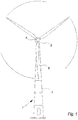
- Fig. 1 is illustrating a large wind turbine, as indicated generally by reference numeral 1.
- the wind turbine 1 comprises a tapered tower 2 and a wind turbine nacelle 3, which is positioned on top of the tower 2.
- the wind turbine nacelle 3 is mounted on the top of the tower 2 to be able for azimuthal rotation around a vertical axis, which is called "yawing", so that the nacelle 3 can follow the direction of wind or can be brought in a specially defined, feathered, position of the rotor blades 5 with reference to the wind direction under given circumstances.
- the wind turbine blades 5 are arranged such that the pitch of each blade 5, i.e. its inclination with respect to the actual wind direction and speed can be adjusted or controlled.
- a pitch can be kept constant or can be varied during one rotation of the rotor 4, the latter for adapting to the wind speed varying with the distance from the ground.
- Rotational positioning systems are especially used for a wind turbine yaw control system to control the yaw of the wind turbine nacelle 3 or for a wind turbine pitch control system to control the pitch of the wind turbine blades 5.
- a wind turbine yaw control system comprises a plurality of yaw drives 102, each including a yaw motor 103 and a yaw gear 104.
- Each of the yaw drives 102 should share the load equally, or according to predefined proportions. Due to the extreme high yaw drive requirement, which has to be fulfilled by a proper yawing system to comply with any operating condition of the wind turbine, the yaw drives 102 are normally dimensioned in such way that any overload relay, that typically is included in the yaw system to protect the same from being damaged by excessive loads, under any normal conditions is never closed to setting.
- a yaw motor 103 or, generally, the yaw drive 102 in the sense that the same does not contribute to the yawing motion is not detected.
- a yaw motor 103 of a yaw drive is loaded not more than 50% during normal operation, thus motor failure might be not detected even if, theoretically, half the number of yaw motors is defective.
- the rotational positioning system comprises positioning drives that in turn each comprises one (or more) positioning motor and a gear via which the positioning motor(s) is coupled to the driven part.
- the positioning drive comprises a positioning motor that is directly (without any intermediate gear) coupled to the driven part.
- the sensor are thus arranged to sense a load parameter for the positioning motor or the gear, in both cases is the load parameter indicative of the load of the one (or more) positioning motor.
- the load parameter is sensed for any part of the positioning drive that is subject to the torque transmission from the positioning motor to the driven part provided that this load parameter is indicative of the load applied by the positioning motor.
- two or more positioning motors are coupled together by one common gear, such as an differential gear, to the driven part.
- the sensors for sensing the load parameter are arranged to sense a load parameter indicative of the effective motor power, in particular an electric motor current, of the respective positioning motor.
- the sensors are arranged to sense a load parameter indicative of the mechanical torque of the positioning drive.
- the mechanical torque of the positioning drive may by sensed at any of its parts that is subject to the torque transmission from the positioning motor to the driven part.
- the load controller is arranged to output a signal indicative of failure of the respective positioning drive in response to the load being smaller by more than a predetermined amount than the expected load value.
- the load controller is further arranged to output a signal indicative of failure of the respective positioning drive in response to the load being larger by more than a predetermined amount than the expected load value.
- the controller outputs a failure signal for a positioning drive that is not only working below normal load but that is also working a predetermined amount above normal load (such as in a jamming situation).
- the load controller is arranged to compare the load of a respective positioning drive with the expected load value during given operating intervals of the rotational positioning system, and to output a signal indicative of a failure of the positioning drive in response to the load being smaller or higher by a predetermined amount than the expected load value during all or at least a part of the given operating intervals or during all or at least a part of each of the given operating intervals.
- the operating intervals may be chosen such that normal load distribution to the positioning drives is to be expected during such an operating interval, such as excluding starting and braking intervals. Considering a plurality of such successive operating intervals, such as a number of successive rotational movement operations of the rotational positioning system, minimizes the risk of a misdiagnosis of the failure of a positioning motor.
- the operating intervals are relatively short, as those of a single positioning operation, or they are longer, as hours, days or weeks, comprising a large number of positioning operations.
- the rotational positioning system is arranged to control the yaw of the wind turbine, in particular the pivotable connection between a wind turbine tower and a wind turbine nacelle.
- the driven part is a yaw ring
- the positioning drive includes a yaw motor and a pinion meshing with the yaw ring.
- some or all positioning motors are grouped together into a plurality of motor groups and each motor group is coupled via one gear, such as a differential gear, to the yaw ring. Thereby, only a part or all of the positioning motors of one motor group are equipped with the sensors for sensing the load parameter.
- the rotational positioning system is arranged to control a pitch of the wind turbine blades.
- the wind turbine rotor 4 comprises three rotor blades 5, which are mounted to the hub 14, but in other embodiments, the wind turbine rotor 4 might comprise another number of blades 5, such as two, four or more blades.
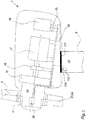
- Fig. 2 is showing a simplified cross-section of the nacelle 3 of a so-called pitch-regulated wind turbine 1, as seen from the side.
- Nacelles 3 may exist in a multitude of variations and configurations, e.g. a drive train in the nacelle 3, following the low speed shaft to which the wind turbine rotor 4 is fixed, comprises one or more of the following components: a gear 15 for changing the (low) rotational speed of the rotor 4 to an elevated rotational speed, some sort of brake system 16, and a generator 17 for converting the mechanical energy provided from the wind turbine rotor 4 to electrical energy.
- the nacelle 3 of a modern wind turbine 1 might also include a converter (or inverter) 18 for converting the electrical energy output from the generator 17 to a voltage with appropriate amplitude, frequency and phase for complying with the electrical grid requirements.
- a converter or inverter
- peripheral equipment such as further power handling equipment, control equipment, hydraulic systems, cooling systems and more.
- the weight of the entire nacelle 3, including the nacelle components 15, 16, 17, 18, is carried by a strengthening structure 19.
- the above described components 15, 16, 17, 18 may be placed on and/or connected to such a common load carrying structure 19.
- the strengthening structure 19 only extends along the bottom of the nacelle 3, e.g. in form of a bed frame, to which some or all the components 15, 16, 17, 18 are connected.
- the strengthening structure 19 might comprise a so-called gear bell transferring the load from the rotor 4 directly to the tower 2, or the load carrying structure 19 might comprise several interconnected parts, such as in a lattice work.
- the drive train of the nacelle 3 is arranged in an angle relatively to a horizontal plane, e.g. for ensuring that the rotor blades 5 do not hit the tower 2, for compensating for differences in wind speed at the top and the bottom of the wind turbine rotor 4, and other reasons.
- yaw controlling system which includes a controller 25 and a yaw system 24.
- the yaw system 24 includes drives 102 to keep the rotor yawed against the wind by rotating the nacelle 3 on the top of the tower 2.
- the yaw system 24 shown in Fig. 2 comprises a yaw positioning drive 102 which is cooperating with a toothed ring 101 by means of a pinion gear 105, all those components illustrated in Fig. 2 in a very simplified manner.
- the yaw system is activated by the controller 25, which is, only for the purpose of example, in the embodiment of Fig. 2 , shown as included in the rotor 4, for controlling the yaw angle or the yaw position, e.g. on the basis of a position feedback signal from a position sensor.
- the controller 25 might be placed in the nacelle 3, in the tower 2, or at another appropriate place.
- the wind turbine blades 5 of the rotor 4 are connected to the hub 14 pivotably around the longitudinal axis of the blades 5, i.e. in such a way to enable variation of the blade pitch relatively to the wind.
- the controller 25 will feather the blades 5 to make the rotor 4 stop rotating, or at least make the rotor 4 idle, and the wind turbine will substantially stop producing power to the utility grid.
- the pitch control of the rotor blades 5 is performed by a pitch control system or pitch positioning drives 21, 22, which in Fig. 2 , for the sake of simplicity and as an example only, are shown near the root 29 of the blades 5.
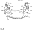
- Fig. 3 is showing, in a perspective, simplified view, some essential parts of a wind turbine yaw system, as known per se from the state of the art.
- This comprises a yaw ring 101 and a plurality of yaw drives 102 each including a yaw motor 103 and a yaw gear 104, wherein the yaw gear 104 of each yaw drive 102 is coupled to the yaw ring 101 by a yaw pinion 105, the latter meshing with the yaw ring 101.
- a yaw system typically, is provided in the connection between the wind turbine tower 2 and the wind turbine nacelle 3 of a wind turbine, as it is shown at reference numeral 24 in Fig. 2 .
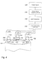
- FIG. 4 one embodiment of the inventive yaw system is shown in a simplified manner, partially in perspective view, partially in form of a block diagram.
- the yaw system comprises a yaw ring 101 and a plurality of yaw drives 102 each including a yaw motor 103 and a yaw gear 104, wherein the yaw gear 104 is coupled to the yaw ring 101 by a yaw pinion 105, the latter meshing with the yaw ring 101.
- Fig. 3 shows a yaw system, in which the yaw drives 102 are arranged outside of the yaw ring 101, the yaw pinions 105 meshing with teeth of the yaw ring 101 on the outer circumference of the same, in Fig.
- yaw drives 102 are arranged inside the yaw ring 101, the yaw pinion 105 meshing with teeth of the yaw ring 101 on the inner circumference of the same, only by the way of an example.
- Fig. 3 shows an arrangement including four yaw drives 102, whereas in Fig. 4 , only for the sake of simplicity, there are shown only three yaw drives 102.
- the yaw system includes a plurality of yaw motors 103 within any kind of yaw drive 102 for driving the yaw system, and a plurality of sensors 111 for sensing a load parameter of a respective yaw motor 103 or, generally, the yaw drive 102.
- Fig. 4 here are shown three yaw drives 102, each comprising one yaw motor 103 and one yaw gear 104, the latter meshing with the yaw ring 101 of the yaw system by one yaw pinion 105, each.
- each one of those yaw drives 102 has an associated sensor 111 for sensing the load parameter.
- the sensors 11 are coupled to a load controller, which is arranged to perform the following steps, for instance by the components 112, 113, 114, 115 as shown in Fig. 4 .
- a load controller which is arranged to perform the following steps, for instance by the components 112, 113, 114, 115 as shown in Fig. 4 .
- a first step e.g. performed by calculator 112 it determines a load of a respective yaw motor 103 based on the load parameter sensed by the sensors 111.
- a second step e.g. performed by a comparator 113 it compares this load with an expected load value.
- a third step e.g. performed by an outputting device 114) it outputs a signal 115 indicative of failure of the respective yaw motor in response to the load being smaller than the expected load value.
- Such an expected load value may be based on the mean load value of the plurality of yaw motors 103 of the yaw system, provided that the yaw motors 103 are similar or identical. In case that, for reasons whatever, there are differences in the yaw drives 102 or yaw motors 103, as regards their power or load carrying ability, such differences are taken in consideration when determining the mean load value.
- the sensors 111 can be arranged to sense a load parameter, which is indicative of the effective power of the yaw motors 103, they can be arranged to sense an effective electric motor current of the yaw motors 103 as the load parameter, or the sensors 111 can be arranged to sense a mechanical torque of the yaw motors 103 or, generally, the yaw drives 102 as the load parameter.
- the load controller 112, 113, 114, 115 may further be arranged to compare, based on the sensed load parameter, the load of the respective yaw motor 103 with the expected load value, and to additionally output a signal indicative of failure in response to the load being larger by more than a given amount than the expected load value.
- the load controller 112, 113, 114, 115 maybe arranged to compare, based on the sensed load parameter, the load of the respective yaw motor 103 or yaw drive 102 with the expected load value during given operating intervals of the yaw system, and to output the signal indicative of failure, in response to the load being larger than the expected load value during all or at least a part of all the given operating intervals or during all or at least a part of a each the given operating intervals.
- any significant deviation of the sensed load from the expected load value in the sense of being significantly smaller, but on the other hand also when being significantly larger than the expected load value, may be considered as an indication of failure of one of the elements in the yaw drive 102, be it in the yaw motor 103, the yaw gear 104, the yaw pinion 105 or in any other essential part associated with the respective yaw drive 102.
- the detected load based on the sensed load parameter, is significantly smaller than the expected load value, this can be considered as an indication of malfunction in the sense of reduced driving performance, be it for whatever reason.
- the sensed load of a respective yaw motor is compared with an expected load value in such way that the effective power consumption or load on each yaw motor is monitored, and if, on this basis, any failure of a yaw motor or yaw drive is detected, e.g. when a motor uses significantly less power than the others, the load controller will detect this, whereas the wind turbine is still able to continue proper operation.
- the said comparison of the load, detected based on the sensed load parameter, with the expected load value can be based on any appropriate reference value, this may be the mean load value of the plurality of the remaining yaw motors, the mean load value of all the yaw motors, including the respective one under consideration.
- the comparison might also be done by deriving the expected load values from the operating parameters of the wind turbine, i.e. by modeling the expected load value from parameters as wind direction, wind speed, rotational speed of the wind turbine, electric power output from the generator, and other operation parameters, or also by deriving the expected load values from a look-up table to which the operating parameters are input.
- the most appropriate way might be a simple comparison with the mean load or power requirement of the other yaw motors.
Landscapes
- Engineering & Computer Science (AREA)
- Life Sciences & Earth Sciences (AREA)
- Sustainable Development (AREA)
- Sustainable Energy (AREA)
- Chemical & Material Sciences (AREA)
- Combustion & Propulsion (AREA)
- Mechanical Engineering (AREA)
- General Engineering & Computer Science (AREA)
- Physics & Mathematics (AREA)
- Fluid Mechanics (AREA)
- Wind Motors (AREA)
Claims (14)
- Rotationspositionierungssystem in einer Windturbine, umfassend
ein angetriebenes Teil (101),
eine Mehrzahl von Positionierungsantrieben (102), die mit dem angetriebenen Teil (101) gekoppelt sind, und
eine Mehrzahl von Sensoren (111), wobei jeder eingerichtet ist, um einen Lastparameter zu erfassen, der die Last des jeweiligen Positionierungsantriebs (102) angibt, gekennzeichnet, durch
eine Laststeuervorrichtung (112, 113, 114, 115), die mit der Mehrzahl von Sensoren (111) verbunden ist und eingerichtet ist, um eine Last eines jeweiligen Positionierungsantriebs (102) basierend auf dem erfassten Lastparameter zu bestimmen, um die Last mit einem erwarteten Lastwert zu vergleichen und um ein Signal (115), das einen Ausfall des jeweiligen Positionierungsantriebs (102) angibt, als Reaktion darauf auszugeben, dass die Last kleiner als der erwartete Lastwert ist. - Rotationspositionierungssystem nach Anspruch 1, wobei die Laststeuervorrichtung (112, 113, 114, 115) eingerichtet ist, um den erwarteten Lastwert als den mittleren Lastwert der Mehrzahl von Positionierungsantrieben (102) zu bestimmen.
- Rotationspositionierungssystem nach Anspruch 1 oder 2, wobei die Positionierungsantriebe (102) Positionierungsmotoren (103) umfassen und die Sensoren (111) eingerichtet sind, um einen Lastparameter zu erfassen, der eine effektive Motorleistung des jeweiligen Positionierungsantriebsmotors (103) angibt.
- Rotationspositionierungssystem nach Anspruch 1 oder 2, wobei die Positionierungsantriebe (102) elektrische Positionierungsmotoren (103) umfassen und wobei die Sensoren (111) eingerichtet sind, um einen Lastparameter zu erfassen, der einen Elektromotorstrom des jeweiligen Positionierungsmotors (103) angibt.
- Rotationspositionierungssystem nach Anspruch 1 oder 2, wobei die Sensoren (111) eingerichtet sind, um einen Lastparameter zu erfassen, der ein mechanisches Drehmoment des jeweiligen Positionierungsantriebs (102) angibt.
- Rotationspositionierungssystem nach einem der vorstehenden Ansprüche, wobei die Laststeuervorrichtung (112, 113, 114, 115) eingerichtet ist, um ein Signal (115), das einen Ausfall des jeweiligen Positionierungsantriebs (102) angibt, als Reaktion darauf auszugeben, dass die Last um mehr als einen vorbestimmten Betrag kleiner als der erwartete Lastwert ist.
- Rotationspositionierungssystem nach einem der vorstehenden Ansprüche, wobei die Laststeuervorrichtung (112, 113, 114, 115) eingerichtet ist, um die Last eines jeweiligen Positionierungsantriebs (102) während vorgegebener Betriebsintervalle des Rotationspositionierungssystems mit dem erwarteten Lastwert zu vergleichen, und um ein Signal (115), das einen Ausfall des jeweiligen Positionierungsantriebs (102) angibt, als Reaktion darauf auszugeben, dass die Last während aller oder zumindest eines Teils aller der gegebenen Betriebsintervalle oder während aller oder zumindest eines Teils von jedem der gegebenen Betriebsintervalle kleiner als der erwartete Lastwert ist.
- Rotationspositionierungssystem nach Anspruch 7, wobei die Laststeuervorrichtung (112, 113, 114, 115) eingerichtet ist, um zusätzlich ein Signal, das einen Ausfall des jeweiligen Positionierungsantriebs (102) angibt, als Reaktion darauf auszugeben, dass die Last um mehr als einen vorbestimmten Betrag größer als der erwartete Lastwert ist.
- Rotationspositionierungssystem nach einem der vorstehenden Ansprüche, eingerichtet, um die Nachführung der Windturbine zu steuern, wobei das angetriebene Teil (101) ein Nachführring (101) ist und der Positionierungsantrieb (102) einen Nachführmotor (103) und ein Nachführritzel (105) umfasst, das mit dem Nachführring (102) in Eingriff ist.
- Rotationspositionierungssystem nach einem der vorstehenden Ansprüche, eingerichtet, um die Winkeleinstellung von Windturbinenblättern zu steuern.
- Verfahren zum Rotationspositionieren eines angetriebenen Teils (101) in einer Windturbine, umfassend die Schritte von:Antreiben des angetriebenen Teils (101) mittels einer Mehrzahl von Positionierungsantrieben (102), undErfassen eines Lastparameters, der die Last eines jeweiligen Positionierungsantriebs (102) angibt, gekennzeichnet, durchBestimmen einer Last eines jeweiligen Positionierungsantriebs (102) basierend auf dem erfassten Lastparameter,Vergleichen der Last mit einem erwarteten Lastwert, undAusgeben eines Signals (115), das einen Ausfall des jeweiligen Positionierungsantriebs (102) angibt, als Reaktion darauf, dass die Last kleiner als der erwartete Lastwert ist.
- Verfahren nach Anspruch 11, weiter umfassend den Schritt des Bestimmens des erwarteten Lastwertes als die mittlere Last der Mehrzahl von Positionierungsantrieben (102).
- Verfahren nach Anspruch 11 oder 12, wobei der Schritt des Erfassens eines Lastparameters den Schritt des Erfassens eines Lastparameters umfasst, der eine effektive Motorleistung des jeweiligen Positionierungsantriebs (102) angibt.
- Verfahren nach Anspruch 13, wobei der Schritt des Erfassens eines Lastparameters den Schritt des Erfassens eines Lastparameters umfasst, der einen Elektromotorstrom des jeweiligen Positionierungsantriebs (102) angibt.
Applications Claiming Priority (3)
| Application Number | Priority Date | Filing Date | Title |
|---|---|---|---|
| US35957610P | 2010-06-29 | 2010-06-29 | |
| DKPA201000565 | 2010-06-29 | ||
| PCT/DK2011/050235 WO2012000504A1 (en) | 2010-06-29 | 2011-06-24 | Rotational positioning system in a wind turbine |
Publications (2)
| Publication Number | Publication Date |
|---|---|
| EP2588751A1 EP2588751A1 (de) | 2013-05-08 |
| EP2588751B1 true EP2588751B1 (de) | 2019-08-07 |
Family
ID=44627836
Family Applications (1)
| Application Number | Title | Priority Date | Filing Date |
|---|---|---|---|
| EP11729049.4A Active EP2588751B1 (de) | 2010-06-29 | 2011-06-24 | Rotationspositionierungssystem bei einer windturbine |
Country Status (3)
| Country | Link |
|---|---|
| US (2) | US9869298B2 (de) |
| EP (1) | EP2588751B1 (de) |
| WO (1) | WO2012000504A1 (de) |
Families Citing this family (32)
| Publication number | Priority date | Publication date | Assignee | Title |
|---|---|---|---|---|
| DE102011077613A1 (de) * | 2011-06-16 | 2012-12-20 | AVAILON GmbH | Windnachführungsanordnung und Verfahren zur Nachführung eines Rotors einer Windenergieanlage sowie Überwachungsvorrichtung hierfür |
| EP2626679A1 (de) * | 2012-02-10 | 2013-08-14 | Siemens Aktiengesellschaft | Verfahren zur Bestimmung des Schadens von mindestens einer drehbaren Komponente einer Windturbine |
| EP2917570B1 (de) | 2012-11-09 | 2019-02-27 | Vestas Wind Systems A/S | Windturbinengiersteuerungssysteme |
| DE102012220502A1 (de) * | 2012-11-09 | 2014-06-12 | Wobben Properties Gmbh | Windenergieanlage |
| EP2754887B1 (de) * | 2013-01-14 | 2016-01-06 | ALSTOM Renewable Technologies | Verfahren zum Betreiben eines Windturbinenrotationssystems sowie Windturbinenrotationssystem |
| EP2754886B1 (de) * | 2013-01-14 | 2016-01-06 | ALSTOM Renewable Technologies | Verfahren zum Betreiben eines Windturbinenrotationssystems sowie Windturbinenrotationssystem |
| EP3163074B1 (de) | 2014-06-24 | 2020-04-22 | NTN Corporation | Zustandsüberwachungssystem und windenergieerzeugungssystem damit |
| JP6320218B2 (ja) * | 2014-07-29 | 2018-05-09 | Ntn株式会社 | 状態監視システム及びそれを備えた風力発電システム |
| EP3176427A4 (de) * | 2014-07-29 | 2018-03-14 | NTN Corporation | Zustandsüberwachungssystem und windenergieerzeugungssystem damit |
| JP6476089B2 (ja) * | 2015-07-28 | 2019-02-27 | 株式会社日立製作所 | 風力発電システム |
| US11280316B2 (en) | 2015-11-20 | 2022-03-22 | Liebherr-Components Biberach Gmbh | Adjustment and/or drive unit, wind turbine having same, and method for controlling same |
| DE102016002006A1 (de) | 2015-11-20 | 2017-05-24 | Liebherr-Components Biberach Gmbh | Verstelleinheit, Windkraftanlage mit einer solchen Verstelleinheit und Verfahren zum Steuern einer solchen Verstelleinheit |
| WO2018091144A1 (de) * | 2016-11-18 | 2018-05-24 | Liebherr-Components Biberach Gmbh | Verstell- und/oder antriebseinheit, windkraftanlage mit einer solchen verstell- und/oder antriebseinheit und verfahren zum steuern einer solchen verstell- und/oder antriebseinheit |
| JP6821344B2 (ja) * | 2016-07-08 | 2021-01-27 | ナブテスコ株式会社 | 風車駆動システム及び風車 |
| JP6821345B2 (ja) * | 2016-07-08 | 2021-01-27 | ナブテスコ株式会社 | 風車駆動システム及び風車 |
| EP3273054B1 (de) | 2016-07-20 | 2019-03-27 | Nordex Energy GmbH | Verfahren zur bestimmung einer einbauposition für einen drehantrieb in einer windenergieanlage |
| DE102016114184A1 (de) * | 2016-08-01 | 2018-02-01 | Wobben Properties Gmbh | Maschinenhaus und Rotor für eine Windenergieanlage sowie Verfahren |
| JP6968532B2 (ja) * | 2016-12-05 | 2021-11-17 | ナブテスコ株式会社 | 風車用駆動装置、風車用駆動装置ユニット及び風車 |
| JP6921514B2 (ja) | 2016-12-07 | 2021-08-18 | ナブテスコ株式会社 | 風車駆動システム及び風車 |
| ES2907237T3 (es) | 2016-12-22 | 2022-04-22 | Vestas Wind Sys As | Medición de corrientes de transductores en un generador de aerogenerador |
| WO2018157897A1 (en) * | 2017-03-01 | 2018-09-07 | Vestas Wind Systems A/S | Yaw system monitor for a multi-rotor wind turbine system |
| CN107288815B (zh) * | 2017-08-08 | 2019-05-10 | 天津亿诺电气设备有限公司 | 一种风力发电偏航调整系统 |
| EP3450745B1 (de) | 2017-09-04 | 2020-07-01 | Siemens Gamesa Renewable Energy A/S | Verfahren zum betrieb einer windturbinenazimutanordnung |
| WO2019229081A1 (en) * | 2018-05-29 | 2019-12-05 | Mhi Vestas Offshore Wind A/S | Geared transmission device and operating method thereof in case of gear damage |
| EP3594493B1 (de) * | 2018-07-12 | 2020-09-09 | Bonfiglioli Riduttori S.p.A. | Verfahren zur überwachung mechanisher belastungen eines stellantriebs zur drehpositionierung eines beweglichen bauteils einer windkraftanlage |
| US11788511B2 (en) * | 2018-12-20 | 2023-10-17 | Vestas Wind Systems A/S | Method and apparatus for testing a yaw system |
| DK3771818T3 (da) * | 2019-07-31 | 2022-07-04 | General Electric Renovables Espana Sl | En nacelleenhed til en vindmølle |
| CN112576440A (zh) * | 2019-09-30 | 2021-03-30 | 北京金风科创风电设备有限公司 | 风力发电机组及其控制方法和装置、计算机可读存储介质 |
| US12025097B2 (en) | 2020-03-30 | 2024-07-02 | Vestas Wind Systems A/S | Controlling the yaw to reduce motor speed |
| JP2021174114A (ja) * | 2020-04-21 | 2021-11-01 | ナブテスコ株式会社 | 状態監視装置及び状態監視方法 |
| CN116113761A (zh) * | 2020-06-16 | 2023-05-12 | 维斯塔斯风力系统集团公司 | 用于风力涡轮机的分段带齿偏航环的偏航驱动装置的控制 |
| JP7512134B2 (ja) * | 2020-09-04 | 2024-07-08 | ナブテスコ株式会社 | 出力装置、状態監視装置、風車、出力方法、状態監視方法及びプログラム |
Citations (5)
| Publication number | Priority date | Publication date | Assignee | Title |
|---|---|---|---|---|
| US5278773A (en) | 1990-09-10 | 1994-01-11 | Zond Systems Inc. | Control systems for controlling a wind turbine |
| US20030160456A1 (en) | 2000-05-12 | 2003-08-28 | Aloys Wobben | Azimuth drive for wind energy plants |
| EP2037119A1 (de) | 2007-09-12 | 2009-03-18 | Siemens Aktiengesellschaft | Giersteuerungsystem für Windturbine zur Giermomentverringerung |
| EP2189656A2 (de) | 2008-11-20 | 2010-05-26 | Vestas Wind Systems A/S | Giersteuerungsystem für Windturbine |
| US20100138060A1 (en) | 2009-09-18 | 2010-06-03 | General Electric Company | Systems, methods, and apparatus for monitoring and controlling a wind driven machine |
Family Cites Families (9)
| Publication number | Priority date | Publication date | Assignee | Title |
|---|---|---|---|---|
| DE3722022C1 (en) | 1987-07-03 | 1988-09-01 | Messerschmitt Boelkow Blohm | Actuator |
| AU2001274396A1 (en) * | 2000-05-23 | 2001-12-03 | Vestas Wind Systems A/S | Variable speed wind turbine having a matrix converter |
| US6769873B2 (en) * | 2002-10-08 | 2004-08-03 | The United States Of America As Represented By The Secretary Of The Navy | Dynamically reconfigurable wind turbine blade assembly |
| EP1571334A1 (de) | 2004-03-04 | 2005-09-07 | Gamesa Eolica, S.A. (Sociedad Unipersonal) | Vorrichtung und Verfahren zur Windnachführung einer Windturbine |
| US7086834B2 (en) * | 2004-06-10 | 2006-08-08 | General Electric Company | Methods and apparatus for rotor blade ice detection |
| WO2008053017A2 (en) | 2006-11-03 | 2008-05-08 | Vestas Wind Systems A/S | A yawing system for a wind turbine |
| WO2008074324A2 (en) | 2006-12-18 | 2008-06-26 | Vestas Wind Systems A/S | Method and system of performing a functional test of at least one embedded sub-element of a wind turbine |
| WO2009068036A2 (en) | 2007-11-30 | 2009-06-04 | Vestas Wind Systems A/S | A wind turbine, a method for controlling a wind turbine and use thereof |
| US7944067B2 (en) * | 2008-04-01 | 2011-05-17 | General Electric Company | System and method for reducing rotor loads in a wind turbine upon detection of blade-pitch failure and loss of counter-torque |
-
2011
- 2011-06-24 EP EP11729049.4A patent/EP2588751B1/de active Active
- 2011-06-24 WO PCT/DK2011/050235 patent/WO2012000504A1/en active Application Filing
- 2011-06-24 US US13/807,517 patent/US9869298B2/en active Active
-
2017
- 2017-12-07 US US15/834,208 patent/US10612520B2/en active Active
Patent Citations (5)
| Publication number | Priority date | Publication date | Assignee | Title |
|---|---|---|---|---|
| US5278773A (en) | 1990-09-10 | 1994-01-11 | Zond Systems Inc. | Control systems for controlling a wind turbine |
| US20030160456A1 (en) | 2000-05-12 | 2003-08-28 | Aloys Wobben | Azimuth drive for wind energy plants |
| EP2037119A1 (de) | 2007-09-12 | 2009-03-18 | Siemens Aktiengesellschaft | Giersteuerungsystem für Windturbine zur Giermomentverringerung |
| EP2189656A2 (de) | 2008-11-20 | 2010-05-26 | Vestas Wind Systems A/S | Giersteuerungsystem für Windturbine |
| US20100138060A1 (en) | 2009-09-18 | 2010-06-03 | General Electric Company | Systems, methods, and apparatus for monitoring and controlling a wind driven machine |
Non-Patent Citations (1)
| Title |
|---|
| ANONYMOUS: "Application ideas for programmable motor-load sensors", MACHINE DESIGN, 1 May 2000 (2000-05-01), pages 1 - 12, XP055735429, Retrieved from the Internet <URL:https://www.machinedesign.com/automation-iiot/sensors/article/21829028/application-ideas-for-programmable-motorload-sensors> [retrieved on 20200930] |
Also Published As
| Publication number | Publication date |
|---|---|
| US9869298B2 (en) | 2018-01-16 |
| US20180135598A1 (en) | 2018-05-17 |
| US20130115043A1 (en) | 2013-05-09 |
| WO2012000504A1 (en) | 2012-01-05 |
| US10612520B2 (en) | 2020-04-07 |
| EP2588751A1 (de) | 2013-05-08 |
Similar Documents
| Publication | Publication Date | Title |
|---|---|---|
| US10612520B2 (en) | Rotational positioning system in a wind turbine | |
| EP2264315B1 (de) | Bedienung einer Windturbine bei Übertemperaturzustand des Motors | |
| EP2067989B1 (de) | System und Verfahren zum Steuern einer Windkraftanlage | |
| EP2440780B1 (de) | Windkraftanlagensteuerung zur vermeidung des abschaltens durch häufige ursachen | |
| EP1612414B1 (de) | Verfahren sowie Vorrichtung zur Reduktion der Rotorbelastungen einer Windenergieanlage | |
| EP2108825B1 (de) | System und Verfahren zur Reduzierung der Rotorbelastung in einer Windturbine bei Erkennung eines Schaufelneigungsfehlers oder eines Drehmomentverlustes | |
| EP2067988B1 (de) | Verfahren und Vorrichtung zur Reduktion der asymmetrischen Rotorlasten beim Abstellen einer Windturbine | |
| EP2306007B1 (de) | Verfahren und System zur Steuerung einer Windturbine | |
| EP2169219B1 (de) | System und Verfahren zur Steuerung einer Windturbine bei elektrischen Energieversorgungsnetzverlust und verändernden Windverhältnissen | |
| EP2963284B1 (de) | Verfahren und systeme zum betrieb eines windturbinensystems | |
| EP3023635A1 (de) | System und verfahren zur überwachung und steuerung der windturbinenblattablenkung | |
| EP2644888A2 (de) | Steuerungssystem und -verfahren zur Vermeidung von Überdrehzahlen bei einer Windturbine | |
| EP2177754A2 (de) | Blattwinkelverwaltungsverfahren und Verwaltungssystem. | |
| EP2848805B1 (de) | Verfahren zum Betrieb einer Windturbine | |
| EP3599375A1 (de) | System und verfahren zum schutz von windturbinen während einer extremen windrichtungsänderung | |
| EP4361434A1 (de) | Schutz von windturbinenkomponenten während des gierens | |
| DK2851559T3 (en) | Method and device for controlling the rotor movement of a wind turbine rotor | |
| ES2742777T3 (es) | Sistema de posicionamiento rotacional en una turbina eólica | |
| JP2023165630A (ja) | 風力タービン制御 | |
| EP2381095A1 (de) | Rotationsanstellantrieb in einer Windturbine |
Legal Events
| Date | Code | Title | Description |
|---|---|---|---|
| PUAI | Public reference made under article 153(3) epc to a published international application that has entered the european phase |
Free format text: ORIGINAL CODE: 0009012 |
|
| 17P | Request for examination filed |
Effective date: 20130125 |
|
| AK | Designated contracting states |
Kind code of ref document: A1 Designated state(s): AL AT BE BG CH CY CZ DE DK EE ES FI FR GB GR HR HU IE IS IT LI LT LU LV MC MK MT NL NO PL PT RO RS SE SI SK SM TR |
|
| DAX | Request for extension of the european patent (deleted) | ||
| RAP1 | Party data changed (applicant data changed or rights of an application transferred) |
Owner name: VESTAS WIND SYSTEMS A/S |
|
| STAA | Information on the status of an ep patent application or granted ep patent |
Free format text: STATUS: EXAMINATION IS IN PROGRESS |
|
| 17Q | First examination report despatched |
Effective date: 20170309 |
|
| REG | Reference to a national code |
Ref country code: DE Ref legal event code: R079 Ref document number: 602011061038 Country of ref document: DE Free format text: PREVIOUS MAIN CLASS: F03D0007020000 Ipc: F03D0017000000 |
|
| RIC1 | Information provided on ipc code assigned before grant |
Ipc: F03D 17/00 20160101AFI20181219BHEP Ipc: F03D 7/04 20060101ALI20181219BHEP Ipc: F03D 7/02 20060101ALI20181219BHEP |
|
| GRAP | Despatch of communication of intention to grant a patent |
Free format text: ORIGINAL CODE: EPIDOSNIGR1 |
|
| STAA | Information on the status of an ep patent application or granted ep patent |
Free format text: STATUS: GRANT OF PATENT IS INTENDED |
|
| INTG | Intention to grant announced |
Effective date: 20190201 |
|
| GRAS | Grant fee paid |
Free format text: ORIGINAL CODE: EPIDOSNIGR3 |
|
| GRAA | (expected) grant |
Free format text: ORIGINAL CODE: 0009210 |
|
| STAA | Information on the status of an ep patent application or granted ep patent |
Free format text: STATUS: THE PATENT HAS BEEN GRANTED |
|
| AK | Designated contracting states |
Kind code of ref document: B1 Designated state(s): AL AT BE BG CH CY CZ DE DK EE ES FI FR GB GR HR HU IE IS IT LI LT LU LV MC MK MT NL NO PL PT RO RS SE SI SK SM TR |
|
| REG | Reference to a national code |
Ref country code: GB Ref legal event code: FG4D |
|
| REG | Reference to a national code |
Ref country code: CH Ref legal event code: EP Ref country code: AT Ref legal event code: REF Ref document number: 1164289 Country of ref document: AT Kind code of ref document: T Effective date: 20190815 |
|
| REG | Reference to a national code |
Ref country code: IE Ref legal event code: FG4D |
|
| REG | Reference to a national code |
Ref country code: DE Ref legal event code: R096 Ref document number: 602011061038 Country of ref document: DE |
|
| REG | Reference to a national code |
Ref country code: NL Ref legal event code: MP Effective date: 20190807 |
|
| REG | Reference to a national code |
Ref country code: LT Ref legal event code: MG4D |
|
| PG25 | Lapsed in a contracting state [announced via postgrant information from national office to epo] |
Ref country code: LT Free format text: LAPSE BECAUSE OF FAILURE TO SUBMIT A TRANSLATION OF THE DESCRIPTION OR TO PAY THE FEE WITHIN THE PRESCRIBED TIME-LIMIT Effective date: 20190807 Ref country code: FI Free format text: LAPSE BECAUSE OF FAILURE TO SUBMIT A TRANSLATION OF THE DESCRIPTION OR TO PAY THE FEE WITHIN THE PRESCRIBED TIME-LIMIT Effective date: 20190807 Ref country code: NL Free format text: LAPSE BECAUSE OF FAILURE TO SUBMIT A TRANSLATION OF THE DESCRIPTION OR TO PAY THE FEE WITHIN THE PRESCRIBED TIME-LIMIT Effective date: 20190807 Ref country code: NO Free format text: LAPSE BECAUSE OF FAILURE TO SUBMIT A TRANSLATION OF THE DESCRIPTION OR TO PAY THE FEE WITHIN THE PRESCRIBED TIME-LIMIT Effective date: 20191107 Ref country code: BG Free format text: LAPSE BECAUSE OF FAILURE TO SUBMIT A TRANSLATION OF THE DESCRIPTION OR TO PAY THE FEE WITHIN THE PRESCRIBED TIME-LIMIT Effective date: 20191107 Ref country code: SE Free format text: LAPSE BECAUSE OF FAILURE TO SUBMIT A TRANSLATION OF THE DESCRIPTION OR TO PAY THE FEE WITHIN THE PRESCRIBED TIME-LIMIT Effective date: 20190807 Ref country code: PT Free format text: LAPSE BECAUSE OF FAILURE TO SUBMIT A TRANSLATION OF THE DESCRIPTION OR TO PAY THE FEE WITHIN THE PRESCRIBED TIME-LIMIT Effective date: 20191209 Ref country code: HR Free format text: LAPSE BECAUSE OF FAILURE TO SUBMIT A TRANSLATION OF THE DESCRIPTION OR TO PAY THE FEE WITHIN THE PRESCRIBED TIME-LIMIT Effective date: 20190807 |
|
| REG | Reference to a national code |
Ref country code: AT Ref legal event code: MK05 Ref document number: 1164289 Country of ref document: AT Kind code of ref document: T Effective date: 20190807 |
|
| REG | Reference to a national code |
Ref country code: ES Ref legal event code: FG2A Ref document number: 2742777 Country of ref document: ES Kind code of ref document: T3 Effective date: 20200217 |
|
| PG25 | Lapsed in a contracting state [announced via postgrant information from national office to epo] |
Ref country code: IS Free format text: LAPSE BECAUSE OF FAILURE TO SUBMIT A TRANSLATION OF THE DESCRIPTION OR TO PAY THE FEE WITHIN THE PRESCRIBED TIME-LIMIT Effective date: 20191207 Ref country code: GR Free format text: LAPSE BECAUSE OF FAILURE TO SUBMIT A TRANSLATION OF THE DESCRIPTION OR TO PAY THE FEE WITHIN THE PRESCRIBED TIME-LIMIT Effective date: 20191108 Ref country code: LV Free format text: LAPSE BECAUSE OF FAILURE TO SUBMIT A TRANSLATION OF THE DESCRIPTION OR TO PAY THE FEE WITHIN THE PRESCRIBED TIME-LIMIT Effective date: 20190807 Ref country code: RS Free format text: LAPSE BECAUSE OF FAILURE TO SUBMIT A TRANSLATION OF THE DESCRIPTION OR TO PAY THE FEE WITHIN THE PRESCRIBED TIME-LIMIT Effective date: 20190807 Ref country code: AL Free format text: LAPSE BECAUSE OF FAILURE TO SUBMIT A TRANSLATION OF THE DESCRIPTION OR TO PAY THE FEE WITHIN THE PRESCRIBED TIME-LIMIT Effective date: 20190807 |
|
| PG25 | Lapsed in a contracting state [announced via postgrant information from national office to epo] |
Ref country code: TR Free format text: LAPSE BECAUSE OF FAILURE TO SUBMIT A TRANSLATION OF THE DESCRIPTION OR TO PAY THE FEE WITHIN THE PRESCRIBED TIME-LIMIT Effective date: 20190807 |
|
| PG25 | Lapsed in a contracting state [announced via postgrant information from national office to epo] |
Ref country code: AT Free format text: LAPSE BECAUSE OF FAILURE TO SUBMIT A TRANSLATION OF THE DESCRIPTION OR TO PAY THE FEE WITHIN THE PRESCRIBED TIME-LIMIT Effective date: 20190807 Ref country code: DK Free format text: LAPSE BECAUSE OF FAILURE TO SUBMIT A TRANSLATION OF THE DESCRIPTION OR TO PAY THE FEE WITHIN THE PRESCRIBED TIME-LIMIT Effective date: 20190807 Ref country code: EE Free format text: LAPSE BECAUSE OF FAILURE TO SUBMIT A TRANSLATION OF THE DESCRIPTION OR TO PAY THE FEE WITHIN THE PRESCRIBED TIME-LIMIT Effective date: 20190807 Ref country code: PL Free format text: LAPSE BECAUSE OF FAILURE TO SUBMIT A TRANSLATION OF THE DESCRIPTION OR TO PAY THE FEE WITHIN THE PRESCRIBED TIME-LIMIT Effective date: 20190807 Ref country code: IT Free format text: LAPSE BECAUSE OF FAILURE TO SUBMIT A TRANSLATION OF THE DESCRIPTION OR TO PAY THE FEE WITHIN THE PRESCRIBED TIME-LIMIT Effective date: 20190807 Ref country code: RO Free format text: LAPSE BECAUSE OF FAILURE TO SUBMIT A TRANSLATION OF THE DESCRIPTION OR TO PAY THE FEE WITHIN THE PRESCRIBED TIME-LIMIT Effective date: 20190807 |
|
| REG | Reference to a national code |
Ref country code: DE Ref legal event code: R026 Ref document number: 602011061038 Country of ref document: DE |
|
| PLBI | Opposition filed |
Free format text: ORIGINAL CODE: 0009260 |
|
| PG25 | Lapsed in a contracting state [announced via postgrant information from national office to epo] |
Ref country code: IS Free format text: LAPSE BECAUSE OF FAILURE TO SUBMIT A TRANSLATION OF THE DESCRIPTION OR TO PAY THE FEE WITHIN THE PRESCRIBED TIME-LIMIT Effective date: 20200224 Ref country code: SM Free format text: LAPSE BECAUSE OF FAILURE TO SUBMIT A TRANSLATION OF THE DESCRIPTION OR TO PAY THE FEE WITHIN THE PRESCRIBED TIME-LIMIT Effective date: 20190807 Ref country code: CZ Free format text: LAPSE BECAUSE OF FAILURE TO SUBMIT A TRANSLATION OF THE DESCRIPTION OR TO PAY THE FEE WITHIN THE PRESCRIBED TIME-LIMIT Effective date: 20190807 Ref country code: SK Free format text: LAPSE BECAUSE OF FAILURE TO SUBMIT A TRANSLATION OF THE DESCRIPTION OR TO PAY THE FEE WITHIN THE PRESCRIBED TIME-LIMIT Effective date: 20190807 |
|
| PLAX | Notice of opposition and request to file observation + time limit sent |
Free format text: ORIGINAL CODE: EPIDOSNOBS2 |
|
| 26 | Opposition filed |
Opponent name: SUZLON ENERGY LTD. Effective date: 20200507 |
|
| PG2D | Information on lapse in contracting state deleted |
Ref country code: IS |
|
| PG25 | Lapsed in a contracting state [announced via postgrant information from national office to epo] |
Ref country code: SI Free format text: LAPSE BECAUSE OF FAILURE TO SUBMIT A TRANSLATION OF THE DESCRIPTION OR TO PAY THE FEE WITHIN THE PRESCRIBED TIME-LIMIT Effective date: 20190807 |
|
| PLBB | Reply of patent proprietor to notice(s) of opposition received |
Free format text: ORIGINAL CODE: EPIDOSNOBS3 |
|
| PG25 | Lapsed in a contracting state [announced via postgrant information from national office to epo] |
Ref country code: MC Free format text: LAPSE BECAUSE OF FAILURE TO SUBMIT A TRANSLATION OF THE DESCRIPTION OR TO PAY THE FEE WITHIN THE PRESCRIBED TIME-LIMIT Effective date: 20190807 |
|
| REG | Reference to a national code |
Ref country code: CH Ref legal event code: PL |
|
| PG25 | Lapsed in a contracting state [announced via postgrant information from national office to epo] |
Ref country code: LU Free format text: LAPSE BECAUSE OF NON-PAYMENT OF DUE FEES Effective date: 20200624 |
|
| REG | Reference to a national code |
Ref country code: BE Ref legal event code: MM Effective date: 20200630 |
|
| PG25 | Lapsed in a contracting state [announced via postgrant information from national office to epo] |
Ref country code: LI Free format text: LAPSE BECAUSE OF NON-PAYMENT OF DUE FEES Effective date: 20200630 Ref country code: IE Free format text: LAPSE BECAUSE OF NON-PAYMENT OF DUE FEES Effective date: 20200624 Ref country code: CH Free format text: LAPSE BECAUSE OF NON-PAYMENT OF DUE FEES Effective date: 20200630 |
|
| PG25 | Lapsed in a contracting state [announced via postgrant information from national office to epo] |
Ref country code: BE Free format text: LAPSE BECAUSE OF NON-PAYMENT OF DUE FEES Effective date: 20200630 |
|
| PG25 | Lapsed in a contracting state [announced via postgrant information from national office to epo] |
Ref country code: MT Free format text: LAPSE BECAUSE OF FAILURE TO SUBMIT A TRANSLATION OF THE DESCRIPTION OR TO PAY THE FEE WITHIN THE PRESCRIBED TIME-LIMIT Effective date: 20190807 Ref country code: CY Free format text: LAPSE BECAUSE OF FAILURE TO SUBMIT A TRANSLATION OF THE DESCRIPTION OR TO PAY THE FEE WITHIN THE PRESCRIBED TIME-LIMIT Effective date: 20190807 |
|
| PG25 | Lapsed in a contracting state [announced via postgrant information from national office to epo] |
Ref country code: MK Free format text: LAPSE BECAUSE OF FAILURE TO SUBMIT A TRANSLATION OF THE DESCRIPTION OR TO PAY THE FEE WITHIN THE PRESCRIBED TIME-LIMIT Effective date: 20190807 |
|
| REG | Reference to a national code |
Ref country code: DE Ref legal event code: R100 Ref document number: 602011061038 Country of ref document: DE |
|
| PLCK | Communication despatched that opposition was rejected |
Free format text: ORIGINAL CODE: EPIDOSNREJ1 |
|
| PLBN | Opposition rejected |
Free format text: ORIGINAL CODE: 0009273 |
|
| STAA | Information on the status of an ep patent application or granted ep patent |
Free format text: STATUS: OPPOSITION REJECTED |
|
| 27O | Opposition rejected |
Effective date: 20221201 |
|
| P01 | Opt-out of the competence of the unified patent court (upc) registered |
Effective date: 20230521 |
|
| PGFP | Annual fee paid to national office [announced via postgrant information from national office to epo] |
Ref country code: ES Payment date: 20230721 Year of fee payment: 13 |
|
| PGFP | Annual fee paid to national office [announced via postgrant information from national office to epo] |
Ref country code: GB Payment date: 20240618 Year of fee payment: 14 |
|
| PGFP | Annual fee paid to national office [announced via postgrant information from national office to epo] |
Ref country code: DE Payment date: 20240627 Year of fee payment: 14 |
|
| PGFP | Annual fee paid to national office [announced via postgrant information from national office to epo] |
Ref country code: FR Payment date: 20240625 Year of fee payment: 14 |