EP2588368B1 - Uav having hermetically sealed modularized compartments and fluid drain ports - Google Patents
Uav having hermetically sealed modularized compartments and fluid drain ports Download PDFInfo
- Publication number
- EP2588368B1 EP2588368B1 EP11827126.1A EP11827126A EP2588368B1 EP 2588368 B1 EP2588368 B1 EP 2588368B1 EP 11827126 A EP11827126 A EP 11827126A EP 2588368 B1 EP2588368 B1 EP 2588368B1
- Authority
- EP
- European Patent Office
- Prior art keywords
- fuselage
- unmanned aerial
- aerial vehicle
- amphibious unmanned
- compartments
- Prior art date
- Legal status (The legal status is an assumption and is not a legal conclusion. Google has not performed a legal analysis and makes no representation as to the accuracy of the status listed.)
- Active
Links
Images
Classifications
-
- B—PERFORMING OPERATIONS; TRANSPORTING
- B64—AIRCRAFT; AVIATION; COSMONAUTICS
- B64C—AEROPLANES; HELICOPTERS
- B64C35/00—Flying-boats; Seaplanes
- B64C35/008—Amphibious sea planes
-
- B—PERFORMING OPERATIONS; TRANSPORTING
- B64—AIRCRAFT; AVIATION; COSMONAUTICS
- B64U—UNMANNED AERIAL VEHICLES [UAV]; EQUIPMENT THEREFOR
- B64U10/00—Type of UAV
- B64U10/25—Fixed-wing aircraft
-
- B—PERFORMING OPERATIONS; TRANSPORTING
- B60—VEHICLES IN GENERAL
- B60F—VEHICLES FOR USE BOTH ON RAIL AND ON ROAD; VEHICLES CAPABLE OF TRAVELLING IN OR ON DIFFERENT MEDIA, e.g. AMPHIBIOUS VEHICLES
- B60F5/00—Other vehicles capable of travelling in or on different media
-
- B—PERFORMING OPERATIONS; TRANSPORTING
- B64—AIRCRAFT; AVIATION; COSMONAUTICS
- B64C—AEROPLANES; HELICOPTERS
- B64C25/00—Alighting gear
- B64C25/32—Alighting gear characterised by elements which contact the ground or similar surface
- B64C25/52—Skis or runners
-
- B—PERFORMING OPERATIONS; TRANSPORTING
- B64—AIRCRAFT; AVIATION; COSMONAUTICS
- B64D—EQUIPMENT FOR FITTING IN OR TO AIRCRAFT; FLIGHT SUITS; PARACHUTES; ARRANGEMENT OR MOUNTING OF POWER PLANTS OR PROPULSION TRANSMISSIONS IN AIRCRAFT
- B64D9/00—Equipment for handling freight; Equipment for facilitating passenger embarkation or the like
-
- B—PERFORMING OPERATIONS; TRANSPORTING
- B64—AIRCRAFT; AVIATION; COSMONAUTICS
- B64U—UNMANNED AERIAL VEHICLES [UAV]; EQUIPMENT THEREFOR
- B64U10/00—Type of UAV
- B64U10/70—Convertible aircraft, e.g. convertible into land vehicles
-
- B—PERFORMING OPERATIONS; TRANSPORTING
- B64—AIRCRAFT; AVIATION; COSMONAUTICS
- B64U—UNMANNED AERIAL VEHICLES [UAV]; EQUIPMENT THEREFOR
- B64U20/00—Constructional aspects of UAVs
- B64U20/40—Modular UAVs
-
- B—PERFORMING OPERATIONS; TRANSPORTING
- B64—AIRCRAFT; AVIATION; COSMONAUTICS
- B64U—UNMANNED AERIAL VEHICLES [UAV]; EQUIPMENT THEREFOR
- B64U20/00—Constructional aspects of UAVs
- B64U20/60—UAVs characterised by the material
-
- B—PERFORMING OPERATIONS; TRANSPORTING
- B64—AIRCRAFT; AVIATION; COSMONAUTICS
- B64U—UNMANNED AERIAL VEHICLES [UAV]; EQUIPMENT THEREFOR
- B64U20/00—Constructional aspects of UAVs
- B64U20/80—Arrangement of on-board electronics, e.g. avionics systems or wiring
-
- B—PERFORMING OPERATIONS; TRANSPORTING
- B64—AIRCRAFT; AVIATION; COSMONAUTICS
- B64U—UNMANNED AERIAL VEHICLES [UAV]; EQUIPMENT THEREFOR
- B64U50/00—Propulsion; Power supply
- B64U50/10—Propulsion
- B64U50/19—Propulsion using electrically powered motors
-
- B—PERFORMING OPERATIONS; TRANSPORTING
- B64—AIRCRAFT; AVIATION; COSMONAUTICS
- B64U—UNMANNED AERIAL VEHICLES [UAV]; EQUIPMENT THEREFOR
- B64U60/00—Undercarriages
- B64U60/10—Undercarriages specially adapted for use on water
-
- B—PERFORMING OPERATIONS; TRANSPORTING
- B64—AIRCRAFT; AVIATION; COSMONAUTICS
- B64U—UNMANNED AERIAL VEHICLES [UAV]; EQUIPMENT THEREFOR
- B64U60/00—Undercarriages
- B64U60/50—Undercarriages with landing legs
-
- B—PERFORMING OPERATIONS; TRANSPORTING
- B64—AIRCRAFT; AVIATION; COSMONAUTICS
- B64U—UNMANNED AERIAL VEHICLES [UAV]; EQUIPMENT THEREFOR
- B64U80/00—Transport or storage specially adapted for UAVs
- B64U80/70—Transport or storage specially adapted for UAVs in containers
-
- Y—GENERAL TAGGING OF NEW TECHNOLOGICAL DEVELOPMENTS; GENERAL TAGGING OF CROSS-SECTIONAL TECHNOLOGIES SPANNING OVER SEVERAL SECTIONS OF THE IPC; TECHNICAL SUBJECTS COVERED BY FORMER USPC CROSS-REFERENCE ART COLLECTIONS [XRACs] AND DIGESTS
- Y02—TECHNOLOGIES OR APPLICATIONS FOR MITIGATION OR ADAPTATION AGAINST CLIMATE CHANGE
- Y02T—CLIMATE CHANGE MITIGATION TECHNOLOGIES RELATED TO TRANSPORTATION
- Y02T50/00—Aeronautics or air transport
- Y02T50/60—Efficient propulsion technologies, e.g. for aircraft
Definitions
- Small unmanned aerial vehicles or UAVs typically are designed to be launched from, and land on dry land. Such vehicles are now being sought that can operate while being exposed to, or after being exposed to aquatic environments. For example, it may be preferred to land an unmanned aerial vehicle on water, rather than on land, either to lessen the impact of landing, or because it is more easily retrievable location.
- amphibious aircraft both manned and unmanned, are able to take off and land in water.
- Hand launched amphibious UAVs though are not required to take off from the water, but are required to land on dry land, or on water. Some hand launced UAVs are designed to land by skidding along, or impacting the ground, which is considerably more abrupt than water landings.
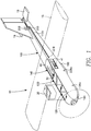
- FIG. 1 shows a simplified perspective view of an amphibious unmanned aerial vehicle or UAV 10.
- the UAV 10 has a fuselage 100 of the amphibious unmanned aerial vehicle 10 has modularized compartments 120, 130, and 140 to contain modular components or modules, such as a battery module 20, a payload module 30, and avionics electronics module 40.
- the wings 15 and/or 16 may be constructed of multiple pieces, which may separate, and/or "break away" or separate from the fuselage 100 during landings.
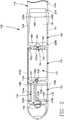
- FIG. 2 shows a simplified top view of the fuselage 100 of the amphibious unmanned aerial vehicle 10 of FIG. 1 .
- the walls 110 of the fuselage 100 are composed of a buoyant material so that the fuselage 100 will float without wings (not shown) attached when the fuselage is fully loaded with components, such as the battery 20, the payload 30, and the avionics electronics 40, shown in FIG. 1 , and other aircraft parts and components.
- the walls 110 have a molded foam core sealed with a waterproof skin.
- the walls 110 may be a single continuous wall or multiple wall sections, or the like.
- the fuselage is separated into three compartments, a forward battery compartment 120, a central payload compartment 130, and a rear avionics compartment 140.
- the forward battery compartment 120 is separated from the central payload compartment 130 by separator wall 150.
- the central payload compartment 130 is separated from the rear avionics compartment 140 by separator wall 160.
- tabs 104, 105, and 106 are employed as a means to secure the components (not shown) in the compartments 120, 130, and 140.
- the tab 105 may be rotated by hand using the pivotable handle 105h to allow installation of a battery (not shown) and then rotated back to the position shown to lock the battery in the forward battery compartment 120.
- Other securing mechanisms may be used instead or in addition to the rotatable tabs 104, 105, and 106.
- the battery compartment 120 has mounting surfaces 122 which support a battery (not show).
- a connector 124 which may be a surface mount connector or the like, is generally flush with the mounting surfaces 122.
- Channels 126f and 126r are recessed below the mounting surfaces 122. Drainage openings such as weep holes 128b in the channel 126f extend through the bottom wall 110b of the fuselage 100.
- Weep holes 128s (shown in FIGS. 1-3 ) in the channel 126r extend through the side wall 110s of the fuselage 100.
- the mating surface 124m of the connector 124 is located above the channels 126f and 126r so that the mating surface is not submerged in water when the battery 20 ( FIG. 1 ) is connected/disconnected, if the fuselage is out of the water.
- Wiring 123f and 123b may be routed in the channels 126f and 126b, respectively, and recessed and/or embedded through the fuselage 100 to provide power to the motor (not show) and avionics electronics module 40 and/or a payload module 30.
- the central payload compartment 130 has front and rear mounting surfaces 132f and 132r which support a payload, such as a camera assembly (not shown).
- the payload module 30 may contain the imaging, sensing, or other passive, active, non-lethal, or lethal payload devices.
- a connector 134 which may be a surface mount connector or the like, is generally flush with the mounting surface 132r.
- the mounting surface 132r may form an enclosure 163 to contain the connector 134 and associated wiring.
- the enclosure may form a lower part of the separator wall 160. Weep holes 228s (shown in FIGS. 1-3 ) may extend from inside the enclosure 163 through the side wall 110s to allow water to exit the enclosure 163.
- the central compartment 130 has a large opening 131 in the bottom so that a camera can be utilized, such as by viewing downward or by lowering it into the airstream through the large opening 131.
- the large opening 131 also allows drainage of fluid from the central compartment 130.
- the mating surface 134m of the connector 134 may be located high above the opening 131, on the top of the enclosure 163, so that the mating surface is not submerged in water when the payload 30 ( FIG. 1 ) is connected/disconnected, even if the fuselage is not completely out of the water.
- the rear avionics compartment 140 has a mounting surface 142 in a bottom of the avionics compartment 140.
- the mounting surface 142 has a forward channel 146f and a rear channel 146r. Channels 146f and 146r are recessed below the mounting surface 142. Drainage openings such as weep hole 228s (shown in FIGS. 1-3 ) in channel 146f extends through the side wall 110s of the fuselage 100. Weep holes 228b (shown in FIGS. 2 and 3 ) in the channel 146r extend through the bottom wall 110b of the fuselage 100. A sloping recess 229 in the mounting surface 142 drains water off the mounting surface 142 and into the channel 146r.
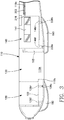
- FIG. 3 has an opening 141 in the side wall 110s of fuselage 110, to expose a heat sink 41 ( FIG. 1 ) and allow heat generated by the avionics electronics 40 ( FIG. 1 ) to be released.
- FIG. 3 shows a simplified side view of the fuselage 100 of an amphibious unmanned aerial vehicle 10 of FIG. 1 .
- optional skid pads 180 and 190 are secured to the bottom wall 110b of the fuselage 100.
- the skid pads 180 and 190 are used in this embodiment for landing on hard surfaces.
- the skid pad 180 may be located directly below the forward compartment 120 and may be fabricated of a durable shock absorbing material of sufficient thickness and density to further protect from impact the component within the compartment 120, such as the battery 20 ( FIG 1 ).
- the skid pad 190 may be located directly below the rear compartment 140, and may be fabricated of a durable shock absorbing material of sufficient thickness and density to further protect from impact a component within the compartment 140, such as the avionics electronics 40 ( FIG. 1 ).
- Weep holes 128s extend through the side wall 110s of the fuselage 100.
- the weep hole 128s extends through the side wall 110s and into rear channel 126r of the battery compartment 120.
- the weep hole 228s extends through the side wall 110s and into the enclosure 163 of the central payload compartment 130.
- the fluid drainage openings may be weep holes, fluid drainage ports, or the like.
- Various embodiments provide a fuselage 100 for a UAV which can land both on water and rugged terrain. Instead of sealing the entire aircraft from water intrusion, various embodiments achieve the ability to land on water by having just the individual electrical and electronic components, i.e. battery, payload, avionics electronics, and associated connectors and wiring, hermetically sealed.
- the aircraft's ability to land on hard surfaces or rugged terrain without damage to the electrical and electronic components is achieved not just by having these components encased in modularized compartments 120, 130, and 140, but also by allowing the walls 110 of the compartments 120, 130, and 140 to be partially compromised without necessarily causing failure of the UAV.
- the walls 110 create an impact zone around the electrical and electronic components within the compartments 120, 130, and 140, and the separators inhibit the components 20, 30, and 40 from impacting each other.
- the walls 110 and mounts 122, 132f, 132r, and 142 are such that the components 20, 30, and 40 ( FIG. 1 ) are recessed from the walls 110 and/or their respective separators 150 and 160 ( FIG. 2 ). Additional shock absorbing material (not shown) may be added within the compartments 120, 130, or 140 to further reduce any chance of damage to the components 20, 30, or 40 from impacts.
- the fuselage 110 may contain an optional exterior channel 110c in the side 110s of the fuselage 110, extending rearward from a hole 218 in the side wall 110s at the avionics compartment 140, to the tail section of the aircraft 10.
- Wiring 203 extends through the hole 218 and along the exterior channel 110c to connect the avionics component 40 to an actuator assembly 202 for actuating the control surfaces in the tail of the aircraft 10.
- the exterior channel 110c allows the wiring to be easily accessed for inspection, repair, and replacement.
- any reference to "one embodiment” or “an embodiment” means that a particular feature, structure, or characteristic described in connection with the embodiment may be included in an embodiment, if desired.
- the appearances of the phrase “in one embodiment” in various places in the specification are not necessarily all referring to the same embodiment.
Landscapes
- Engineering & Computer Science (AREA)
- Aviation & Aerospace Engineering (AREA)
- Remote Sensing (AREA)
- Mechanical Engineering (AREA)
- Chemical & Material Sciences (AREA)
- Combustion & Propulsion (AREA)
- Transportation (AREA)
- Microelectronics & Electronic Packaging (AREA)
- Casings For Electric Apparatus (AREA)
- Battery Mounting, Suspending (AREA)
- Tents Or Canopies (AREA)
- Toys (AREA)
Description
- Reducing weight and size are paramount in the design of small unmanned vehicles. Small unmanned aerial vehicles or UAVs typically are designed to be launched from, and land on dry land. Such vehicles are now being sought that can operate while being exposed to, or after being exposed to aquatic environments. For example, it may be preferred to land an unmanned aerial vehicle on water, rather than on land, either to lessen the impact of landing, or because it is more easily retrievable location. Typically, amphibious aircraft, both manned and unmanned, are able to take off and land in water.
- Hand launched amphibious UAVs though are not required to take off from the water, but are required to land on dry land, or on water. Some hand launced UAVs are designed to land by skidding along, or impacting the ground, which is considerably more abrupt than water landings.
- What is needed is an amphibious UAV that can withstand high impact ground landings.
- From the United States patent
US 1,746,669 aircraft floats are known allowing an aircraft to start and land in water. From the German patent application publication andDE 19957207 A1 a kite is known having drainage openings in the wing. From the United States patentUS 2,309,875 an amphibian vehicle including pontoons with a valve structure is known. From the United States patentUS 3,092,060 an amphibious unmanned aerial vehicle according to the precharacterizing part ofclaim 1 is known. - It is an object of the invention to improve the amphibious unmanned aerial vehicle according to the precharacterizing part of
claim 1 for making the protection of the electrical and electronic components independent of the integrity of the fuselage even if the amphibious unmanned aerial vehicle is landed in water. - The aforementioned and other objects are achieved by the features in the characterizing part of
claim 1. Advantageous further embodiments are claimed in the dependent claims. - The features and advantages of the present invention will be better understood with regard to the following description, appended claims, and accompanying drawings where:
-
FIG. 1 shows a simplified perspective view of an amphibious unmanned aerial vehicle. -
FIG. 2 shows a simplified top view of the fuselage of the amphibious unmanned aerial vehicle ofFIG. 1 . -
FIG. 3 shows a simplified side view of the fuselage of an amphibious unmanned aerial vehicle ofFIG. 1 . -
FIG. 1 shows a simplified perspective view of an amphibious unmanned aerial vehicle orUAV 10. The UAV 10 has afuselage 100 of the amphibious unmannedaerial vehicle 10 hasmodularized compartments battery module 20, apayload module 30, andavionics electronics module 40. In various embodiments, thewings 15 and/or 16 may be constructed of multiple pieces, which may separate, and/or "break away" or separate from thefuselage 100 during landings. -
FIG. 2 shows a simplified top view of thefuselage 100 of the amphibious unmannedaerial vehicle 10 ofFIG. 1 . Thewalls 110 of thefuselage 100 are composed of a buoyant material so that thefuselage 100 will float without wings (not shown) attached when the fuselage is fully loaded with components, such as thebattery 20, thepayload 30, and theavionics electronics 40, shown inFIG. 1 , and other aircraft parts and components. Thewalls 110 have a molded foam core sealed with a waterproof skin. Thewalls 110 may be a single continuous wall or multiple wall sections, or the like. - In this embodiment, the fuselage is separated into three compartments, a
forward battery compartment 120, acentral payload compartment 130, and arear avionics compartment 140. Theforward battery compartment 120 is separated from thecentral payload compartment 130 byseparator wall 150. Thecentral payload compartment 130 is separated from therear avionics compartment 140 byseparator wall 160. In the embodiment shown,tabs compartments tab 105 may be rotated by hand using thepivotable handle 105h to allow installation of a battery (not shown) and then rotated back to the position shown to lock the battery in theforward battery compartment 120. Other securing mechanisms may be used instead or in addition to therotatable tabs - The
battery compartment 120 has mountingsurfaces 122 which support a battery (not show). In this embodiment, aconnector 124, which may be a surface mount connector or the like, is generally flush with themounting surfaces 122.Channels mounting surfaces 122. Drainage openings such asweep holes 128b in thechannel 126f extend through thebottom wall 110b of thefuselage 100. Weepholes 128s (shown inFIGS. 1-3 ) in thechannel 126r extend through theside wall 110s of thefuselage 100. - The
mating surface 124m of theconnector 124 is located above thechannels FIG. 1 ) is connected/disconnected, if the fuselage is out of the water. Wiring 123f and 123b may be routed in thechannels 126f and 126b, respectively, and recessed and/or embedded through thefuselage 100 to provide power to the motor (not show) andavionics electronics module 40 and/or apayload module 30. - The
central payload compartment 130 has front andrear mounting surfaces payload module 30 may contain the imaging, sensing, or other passive, active, non-lethal, or lethal payload devices. In this embodiment, aconnector 134, which may be a surface mount connector or the like, is generally flush with themounting surface 132r. Themounting surface 132r may form anenclosure 163 to contain theconnector 134 and associated wiring. The enclosure may form a lower part of theseparator wall 160. Weepholes 228s (shown inFIGS. 1-3 ) may extend from inside theenclosure 163 through theside wall 110s to allow water to exit theenclosure 163. In this embodiment, thecentral compartment 130 has alarge opening 131 in the bottom so that a camera can be utilized, such as by viewing downward or by lowering it into the airstream through thelarge opening 131. Thelarge opening 131 also allows drainage of fluid from thecentral compartment 130. - In various embodiments, the
mating surface 134m of theconnector 134 may be located high above theopening 131, on the top of theenclosure 163, so that the mating surface is not submerged in water when the payload 30 (FIG. 1 ) is connected/disconnected, even if the fuselage is not completely out of the water. - The
rear avionics compartment 140 has amounting surface 142 in a bottom of theavionics compartment 140. Themounting surface 142 has aforward channel 146f and arear channel 146r.Channels mounting surface 142. Drainage openings such asweep hole 228s (shown inFIGS. 1-3 ) inchannel 146f extends through theside wall 110s of thefuselage 100.Weep holes 228b (shown inFIGS. 2 and3 ) in thechannel 146r extend through thebottom wall 110b of thefuselage 100. A sloping recess 229 in themounting surface 142 drains water off themounting surface 142 and into thechannel 146r. - The embodiment shown in
FIG. 3 has anopening 141 in theside wall 110s offuselage 110, to expose a heat sink 41 (FIG. 1 ) and allow heat generated by the avionics electronics 40 (FIG. 1 ) to be released. -
FIG. 3 shows a simplified side view of thefuselage 100 of an amphibious unmannedaerial vehicle 10 ofFIG. 1 . In this embodiment,optional skid pads bottom wall 110b of thefuselage 100. Theskid pads skid pad 180 may be located directly below theforward compartment 120 and may be fabricated of a durable shock absorbing material of sufficient thickness and density to further protect from impact the component within thecompartment 120, such as the battery 20 (FIG 1 ). Similarly, theskid pad 190 may be located directly below therear compartment 140, and may be fabricated of a durable shock absorbing material of sufficient thickness and density to further protect from impact a component within thecompartment 140, such as the avionics electronics 40 (FIG. 1 ). -
Weep holes 128s extend through theside wall 110s of thefuselage 100. Theweep hole 128s extends through theside wall 110s and intorear channel 126r of thebattery compartment 120. Theweep hole 228s extends through theside wall 110s and into theenclosure 163 of thecentral payload compartment 130. - The fluid drainage openings may be weep holes, fluid drainage ports, or the like.
- Various embodiments provide a
fuselage 100 for a UAV which can land both on water and rugged terrain. Instead of sealing the entire aircraft from water intrusion, various embodiments achieve the ability to land on water by having just the individual electrical and electronic components, i.e. battery, payload, avionics electronics, and associated connectors and wiring, hermetically sealed. - This allows the rest of the aircraft to remain buoyant and any water in the aircraft draining by a set of fluid drain ports when the UAV is retrieved from the water. In this manner, the protection of the electrical and electronic components is not dependant on maintaining the integrity of the
fuselage 100 or theexterior walls 110, which is likely to be damaged during landings on hard and/or rugged surfaces (typical of land landings). - This also allows the volume within the aircraft that needs to be waterproof to be minimized, thus reducing weight and overall system complexity.
- Further, the aircraft's ability to land on hard surfaces or rugged terrain without damage to the electrical and electronic components is achieved not just by having these components encased in
modularized compartments walls 110 of thecompartments walls 110 create an impact zone around the electrical and electronic components within thecompartments components walls 110 and mounts 122, 132f, 132r, and 142 are such that thecomponents FIG. 1 ) are recessed from thewalls 110 and/or theirrespective separators 150 and 160 (FIG. 2 ). Additional shock absorbing material (not shown) may be added within thecompartments components - As illustrated in
FIGS. 1 and2 , thefuselage 110 may contain anoptional exterior channel 110c in theside 110s of thefuselage 110, extending rearward from ahole 218 in theside wall 110s at theavionics compartment 140, to the tail section of theaircraft 10. Wiring 203 extends through thehole 218 and along theexterior channel 110c to connect theavionics component 40 to anactuator assembly 202 for actuating the control surfaces in the tail of theaircraft 10. Theexterior channel 110c allows the wiring to be easily accessed for inspection, repair, and replacement. - It is worthy to note that any reference to "one embodiment" or "an embodiment" means that a particular feature, structure, or characteristic described in connection with the embodiment may be included in an embodiment, if desired. The appearances of the phrase "in one embodiment" in various places in the specification are not necessarily all referring to the same embodiment.
- The illustrations and examples provided herein are for explanatory purposes and are not intended to limit the scope of the appended claims.
Claims (15)
- An amphibious unmanned aerial vehicle comprising:a fuselage (100);separators (150, 160) within the fuselage forming separate compartments within the fuselage; andmounts (122, 142) associated with the compartments for securing waterproof aircraft components within the fuselage;characterized in thatthe walls (110) of the fuselage (100) are comprised of a buoyant material having a molded foam core sealed with a waterproof skin so that the fuselage (100) will float in water without wings attached when the fuselage is fully loaded with a battery (20), a payload (30), and avionics electronics (40); andthe compartments each having water drainage openings (128b, 128s, 131, 228b, 228s) in the fuselage extending from the interior of the fuselage to the exterior of the fuselage (100).
- The amphibious unmanned aerial vehicle of Claim 1, wherein the drainage openings in at least some of the compartments comprise weep holes (128b, 128s, 228b, 228s) through the walls of the fuselage.
- The amphibious unmanned aerial vehicle of Claim 1, wherein at least one of the compartments comprises a drainage channel (126f, 126r, 146r) at a bottom thereof, and wherein the drainage channel comprises at least one drainage opening associated therewith.
- The amphibious unmanned aerial vehicle of Claim 3, wherein the at least one drainage opening comprises a weep hole.
- The amphibious unmanned aerial vehicle of Claim 3, wherein the at least one drainage opening comprises a plurality of weep holes.
- The amphibious unmanned aerial vehicle of Claim 1, wherein the separate compartments comprise:a) a forward battery compartment (120);b) a central payload compartment (130); andc) a rear avionics compartment (140).
- The amphibious unmanned aerial vehicle of Claim 1, further comprising at least one skid pad (180, 190) on a bottom of the fuselage.
- The amphibious unmanned aerial vehicle of Claim 1 further comprising drainage openings extending through the separators within the fuselage.
- The amphibious unmanned aerial vehicle of Claim 1 further comprising securing mechanisms (104, 105, 106) associated with the compartments to secure the waterproof aircraft components in the compartments.
- The amphibious unmanned aerial vehicle of Claim 1, wherein at least some of the mounts within the compartments comprise integrated connectors (124, 134) for electrically connecting a corresponding aircraft component upon mounting of the corresponding aircraft component within a respective compartment.
- The amphibious unmanned aerial vehicle of Claim 1, wherein the compartments comprise a battery compartment comprising a surface mount connector flush with a mounting surface of the mounts within the battery compartment.
- The amphibious unmanned aerial vehicle of Claim 1, wherein the compartments comprise a payload compartment comprising a surface mount connector flush with a mounting surface of the mounts within the payload compartment.
- The amphibious unmanned aerial vehicle of Claim 1, wherein the compartments comprise a payload compartment comprising an open bottom (131).
- The amphibious unmanned aerial vehicle of Claim 13, wherein there is no fuselage wall below the payload compartment.
- The amphibious unmanned aerial vehicle of Claim 1, wherein the compartments comprise an avionics compartment comprising a heat sink opening (141).
Priority Applications (2)
| Application Number | Priority Date | Filing Date | Title |
|---|---|---|---|
| DK20158404.2T DK3693272T3 (en) | 2010-06-29 | 2011-06-29 | Amphibian UAV with fluid drainage openings |
| EP20158404.2A EP3693272B1 (en) | 2010-06-29 | 2011-06-29 | Amphibious uav with fluid drain ports |
Applications Claiming Priority (2)
| Application Number | Priority Date | Filing Date | Title |
|---|---|---|---|
| US35980910P | 2010-06-29 | 2010-06-29 | |
| PCT/US2011/042285 WO2012039810A1 (en) | 2010-06-29 | 2011-06-29 | Uav having hermetically sealed modularized compartments and fluid drain ports |
Related Child Applications (1)
| Application Number | Title | Priority Date | Filing Date |
|---|---|---|---|
| EP20158404.2A Division EP3693272B1 (en) | 2010-06-29 | 2011-06-29 | Amphibious uav with fluid drain ports |
Publications (3)
| Publication Number | Publication Date |
|---|---|
| EP2588368A1 EP2588368A1 (en) | 2013-05-08 |
| EP2588368A4 EP2588368A4 (en) | 2017-12-06 |
| EP2588368B1 true EP2588368B1 (en) | 2020-03-18 |
Family
ID=45874097
Family Applications (2)
| Application Number | Title | Priority Date | Filing Date |
|---|---|---|---|
| EP20158404.2A Active EP3693272B1 (en) | 2010-06-29 | 2011-06-29 | Amphibious uav with fluid drain ports |
| EP11827126.1A Active EP2588368B1 (en) | 2010-06-29 | 2011-06-29 | Uav having hermetically sealed modularized compartments and fluid drain ports |
Family Applications Before (1)
| Application Number | Title | Priority Date | Filing Date |
|---|---|---|---|
| EP20158404.2A Active EP3693272B1 (en) | 2010-06-29 | 2011-06-29 | Amphibious uav with fluid drain ports |
Country Status (11)
| Country | Link |
|---|---|
| US (3) | US9365088B2 (en) |
| EP (2) | EP3693272B1 (en) |
| JP (1) | JP2013530091A (en) |
| KR (3) | KR102024926B1 (en) |
| CN (2) | CN108382583B (en) |
| AU (6) | AU2011305991A1 (en) |
| CA (1) | CA2840554C (en) |
| DK (2) | DK2588368T3 (en) |
| SG (1) | SG188634A1 (en) |
| TW (1) | TW201223828A (en) |
| WO (1) | WO2012039810A1 (en) |
Families Citing this family (59)
| Publication number | Priority date | Publication date | Assignee | Title |
|---|---|---|---|---|
| AU2011305991A1 (en) * | 2010-06-29 | 2013-02-07 | Aerovironment, Inc. | UAV having hermetically sealed modularized compartments and fluid drain ports |
| US12203350B2 (en) | 2013-07-18 | 2025-01-21 | DynaEnergetics Europe GmbH | Detonator positioning device |
| US9702680B2 (en) | 2013-07-18 | 2017-07-11 | Dynaenergetics Gmbh & Co. Kg | Perforation gun components and system |
| CN109372475B (en) | 2013-08-26 | 2021-05-18 | 德国德力能有限公司 | Perforating gun and detonator assembly |
| RU2677513C2 (en) | 2014-03-07 | 2019-01-17 | Динаэнергетикс Гмбх Унд Ко. Кг | Device and method for positioning detonator within perforator assembly |
| IL234058A (en) * | 2014-08-11 | 2017-06-29 | Almog Rescue Systems Ltd | An unmanned glider system for cargo dispersion |
| US9845158B2 (en) | 2014-10-17 | 2017-12-19 | X Development Llc | Aircraft battery containment pods |
| US9784549B2 (en) * | 2015-03-18 | 2017-10-10 | Dynaenergetics Gmbh & Co. Kg | Bulkhead assembly having a pivotable electric contact component and integrated ground apparatus |
| JP6243545B2 (en) * | 2015-06-01 | 2017-12-06 | エスゼット ディージェイアイ テクノロジー カンパニー リミテッドSz Dji Technology Co.,Ltd | UAV with sensor and method for separately arranging sensors |
| CN205989812U (en) | 2015-06-25 | 2017-03-01 | 瑞德利斯技术公司 | Many rotor wing unmanned aerial vehicles |
| WO2017131823A2 (en) * | 2015-09-16 | 2017-08-03 | Christopher Wilkinson | Space combat drone |
| US10529995B2 (en) * | 2015-09-17 | 2020-01-07 | Raytheon Company | Reusable resettable retriggerable rebuildable squibless missile battery |
| CN105314085B (en) * | 2015-10-30 | 2018-11-20 | 易瓦特科技股份公司 | Hand throws unmanned plane |
| US10336453B2 (en) * | 2016-01-14 | 2019-07-02 | Elwha Llc | System and method for payload management for unmanned aircraft |
| WO2017183551A1 (en) | 2016-04-19 | 2017-10-26 | 株式会社プロドローン | Unmanned aerial vehicle |
| CN105923142A (en) * | 2016-05-13 | 2016-09-07 | 深圳市斯威普科技有限公司 | Unmanned aerial vehicle waterproof structure |
| EP3299291B1 (en) | 2016-09-23 | 2020-04-08 | microdrones GmbH | Unmanned aircraft |
| EP3326917A1 (en) * | 2016-11-24 | 2018-05-30 | Airbus Operations GmbH | A structural element, a battery set, an arrangement of a structural element and a battery set, and an aerospace vehicle |
| FR3065440B1 (en) * | 2017-04-24 | 2019-06-07 | Fly-R | VERTICAL LANDING AIRCRAFT RHOMBOEDRICAL VESSEL |
| CN107264822B (en) * | 2017-06-28 | 2023-05-23 | 南京工业职业技术学院 | An aircraft floor drainage device |
| CN111344223A (en) * | 2017-08-01 | 2020-06-26 | 兹普澜国际股份有限公司 | Drone system with swappable parts |
| US10934013B2 (en) * | 2017-09-22 | 2021-03-02 | The Boeing Company | Aircraft fuselage apparatus having embedded structural batteries |
| US10940932B2 (en) * | 2017-10-11 | 2021-03-09 | Wing Aviation Llc | Modular fuselage for unmanned aerial vehicle |
| CN107697280B (en) * | 2017-10-18 | 2023-11-07 | 沈阳旋飞航空技术有限公司 | A load-carrying structure for electric unmanned aerial vehicle |
| JP6649342B2 (en) * | 2017-11-09 | 2020-02-19 | エスゼット ディージェイアイ テクノロジー カンパニー リミテッドSz Dji Technology Co.,Ltd | Unmanned aerial vehicle and method for separating inertial measurement units in an unmanned aerial vehicle |
| US11808093B2 (en) | 2018-07-17 | 2023-11-07 | DynaEnergetics Europe GmbH | Oriented perforating system |
| US11339614B2 (en) | 2020-03-31 | 2022-05-24 | DynaEnergetics Europe GmbH | Alignment sub and orienting sub adapter |
| CN109204812B (en) * | 2018-08-10 | 2020-11-17 | 上海交通大学 | Sea-air amphibious aircraft with fixed wings combined with glider |
| KR102096777B1 (en) * | 2018-09-19 | 2020-04-03 | 주식회사 티지에스코리아 | Unmanned aerial vehicles adopting protection functions |
| CN109436370B (en) * | 2018-09-30 | 2022-02-11 | 中国特种飞行器研究所 | Floating characteristic test model |
| WO2020095435A1 (en) * | 2018-11-09 | 2020-05-14 | 楽天株式会社 | Unmanned flight vehicle |
| CN112278228A (en) * | 2019-07-24 | 2021-01-29 | 广州极飞科技有限公司 | Unmanned vehicles's fuselage and unmanned vehicles who has it |
| CN110450953B (en) * | 2019-08-13 | 2020-12-04 | 江苏锦程航空科技有限公司 | An unmanned aerial device with heat dissipation function for maritime security patrol |
| EP3798124B1 (en) * | 2019-09-30 | 2023-01-18 | Shanghai Autoflight Co., Ltd. | Amphibious drone |
| US10669037B1 (en) * | 2019-11-26 | 2020-06-02 | Kitty Hawk Corporation | Spring-loaded flaps for air cooling in a wet environment |
| CZ310189B6 (en) | 2019-12-10 | 2024-11-06 | DynaEnergetics Europe GmbH | Fuze head, fuze and fuze assembly |
| USD1041608S1 (en) | 2020-03-20 | 2024-09-10 | DynaEnergetics Europe GmbH | Outer connector |
| US11988049B2 (en) | 2020-03-31 | 2024-05-21 | DynaEnergetics Europe GmbH | Alignment sub and perforating gun assembly with alignment sub |
| CN111806174B (en) * | 2020-06-10 | 2022-05-17 | 中山大学 | An aircraft structure that can repeatedly enter and exit the water |
| CN112124553A (en) * | 2020-10-28 | 2020-12-25 | 广州极飞科技有限公司 | Unmanned vehicles's fuselage assembly and unmanned vehicles who has it |
| TWI779431B (en) * | 2020-12-18 | 2022-10-01 | 東友科技股份有限公司 | Drone and battery exchange system thereof |
| WO2022135749A1 (en) | 2020-12-21 | 2022-06-30 | DynaEnergetics Europe GmbH | Encapsulated shaped charge |
| KR102449142B1 (en) * | 2021-01-08 | 2022-09-29 | 주식회사 엠지아이티 | Driving method for vertical take-off and landing and flight conversion of vertical take-off and landing drones and vertical take-off and landing drones |
| WO2022148557A1 (en) | 2021-01-08 | 2022-07-14 | DynaEnergetics Europe GmbH | Perforating gun assembly and components |
| US11542020B2 (en) * | 2021-01-29 | 2023-01-03 | Textron Innovations Inc. | Electric aircraft side access batteries and single file passenger seating |
| US12366142B2 (en) | 2021-03-03 | 2025-07-22 | DynaEnergetics Europe GmbH | Modular perforating gun system |
| US11713625B2 (en) | 2021-03-03 | 2023-08-01 | DynaEnergetics Europe GmbH | Bulkhead |
| WO2022184732A1 (en) | 2021-03-03 | 2022-09-09 | DynaEnergetics Europe GmbH | Bulkhead and tandem seal adapter |
| DE102021110636A1 (en) * | 2021-04-26 | 2022-10-27 | Wingcopter GmbH | Aircraft with a battery pack |
| US12000267B2 (en) | 2021-09-24 | 2024-06-04 | DynaEnergetics Europe GmbH | Communication and location system for an autonomous frack system |
| US12253339B2 (en) | 2021-10-25 | 2025-03-18 | DynaEnergetics Europe GmbH | Adapter and shaped charge apparatus for optimized perforation jet |
| US12312925B2 (en) | 2021-12-22 | 2025-05-27 | DynaEnergetics Europe GmbH | Manually oriented internal shaped charge alignment system and method of use |
| KR102439224B1 (en) * | 2022-01-28 | 2022-09-01 | 주식회사 해양드론기술 | Marine Drone Assemblies |
| US12145753B2 (en) * | 2022-08-09 | 2024-11-19 | Pete Bitar | Compact and lightweight drone delivery device called an ArcSpear electric jet drone system having an electric ducted air propulsion system and being relatively difficult to track in flight |
| KR102804421B1 (en) * | 2022-12-22 | 2025-05-13 | (주)프리뉴 | Canopy for drone |
| US12546194B2 (en) | 2023-08-04 | 2026-02-10 | DynaEnergetics Europe GmbH | Method and apparatus for automatic arming of perforating gun |
| KR102773090B1 (en) * | 2023-12-08 | 2025-02-26 | 주식회사 엠바디텍 | Paper drone with waterproof coating |
| CN222793843U (en) * | 2024-04-01 | 2025-04-25 | 深圳市道通智能航空技术股份有限公司 | Drones |
| KR102907702B1 (en) * | 2025-04-28 | 2026-01-05 | 대영엠엔에스 주식회사 | Unmanned aerial vehicle with pet poam body and manufacturing method thereof |
Family Cites Families (45)
| Publication number | Priority date | Publication date | Assignee | Title |
|---|---|---|---|---|
| US1746669A (en) | 1927-08-01 | 1930-02-11 | Glenn L Martin Co | Airplane |
| US1769406A (en) * | 1928-10-22 | 1930-07-01 | John C Worthington | Amphibian landing gear |
| US2309875A (en) | 1941-07-14 | 1943-02-02 | Theodore F Thompson | Amphibian |
| US2415615A (en) | 1942-02-16 | 1947-02-11 | Edward E Wallace | Airplane |
| GB565692A (en) * | 1943-08-16 | 1944-11-22 | Percival John Taylor | Improvements in or relating to the hulls of flying boats |
| US2444332A (en) * | 1944-12-07 | 1948-06-29 | Briggs Earl | Wing folding arrangement for submersible aircraft |
| US3092060A (en) * | 1958-01-17 | 1963-06-04 | Donald V Reid | Flying submarine |
| ES2011310A6 (en) * | 1987-11-20 | 1990-01-01 | Lopez Ibor Alino Francisco Jos | Two-level sea-land creeping vehicle and method of operating same. |
| US5250845A (en) | 1990-11-30 | 1993-10-05 | Hughes Aircraft Company | Totally enclosed hermetic electronic module |
| US5277380A (en) * | 1992-06-22 | 1994-01-11 | United Technologies Corporation | Toroidal fuselage structure for unmanned aerial vehicles having ducted, coaxial, counter-rotating rotors |
| CN2179334Y (en) * | 1993-07-27 | 1994-10-12 | 国营千山电子仪器厂 | Aeroplane data recorder outer box |
| US5575438A (en) * | 1994-05-09 | 1996-11-19 | United Technologies Corporation | Unmanned VTOL ground surveillance vehicle |
| CN1155329A (en) * | 1994-08-11 | 1997-07-23 | 罗斯蒙德公司 | Transmitter with water draining housing and improved method of mounting RFI filter |
| US5666900A (en) * | 1995-06-05 | 1997-09-16 | Sippican, Inc. | Method and apparatus for deploying an expendable autonomous underwater vehicle from a submarine |
| US5779190A (en) * | 1995-11-22 | 1998-07-14 | Northrop Grumman Corporation | Portable unmanned aerial vehicle |
| DE19700182A1 (en) * | 1997-01-04 | 1998-07-09 | Industrieanlagen Betriebsges | Aircraft with a fuselage designed essentially as an aerostatic buoyancy body |
| US6056237A (en) * | 1997-06-25 | 2000-05-02 | Woodland; Richard L. K. | Sonotube compatible unmanned aerial vehicle and system |
| DE19957207A1 (en) | 1999-11-27 | 2001-05-31 | Gabor Kovacs | Buoyant kite for pulling incorporates a lower sail, chamber walls, a leading edge for lessening water intake, a trailing edge, air intake holes and drainage holes. |
| US6409122B1 (en) * | 2001-01-17 | 2002-06-25 | Lockheed Martin Corporation | Anti-submarine warfare UAV and method of use thereof |
| CN1370715A (en) * | 2001-02-27 | 2002-09-25 | 吴建 | Submerged pipe type floating air intake device |
| US20060102798A1 (en) * | 2001-05-21 | 2006-05-18 | Mission Technologies, Inc. | Unmanned biplane for airborne reconnaissance and surveillance having staggered and gapped wings |
| CN2506541Y (en) * | 2001-07-30 | 2002-08-21 | 罗专予 | Ditachable water sealed cabin for airplane |
| US6840480B2 (en) * | 2001-09-27 | 2005-01-11 | Ernest A. Carroll | Miniature, unmanned aircraft with interchangeable data module |
| DE10201032A1 (en) | 2002-01-11 | 2003-07-24 | Giesecke & Devrient Gmbh | Steel intaglio printing process for producing a security document, as well as steel intaglio printing plate and semi-finished products therefor, and process for their production |
| US6761334B1 (en) | 2003-05-28 | 2004-07-13 | Costica Nutu | Aircraft passenger safety module |
| US6926235B2 (en) * | 2003-06-20 | 2005-08-09 | The Boeing Company | Runway-independent omni-role modularity enhancement (ROME) vehicle |
| EP1646558B1 (en) * | 2003-07-18 | 2006-11-15 | Telair International GmbH | Floor for an aircraft cargo compartment and a method for the assembly thereof |
| US7325772B1 (en) * | 2003-09-04 | 2008-02-05 | L-3 Communications Corporation | Aircraft heat sink and electronics enclosure |
| US7097136B2 (en) * | 2004-04-13 | 2006-08-29 | Lockheed Martin Corporation | Immersible unmanned air vehicle and system for launch, recovery, and re-launch at sea |
| US20060145000A1 (en) | 2004-10-27 | 2006-07-06 | Robert Hensley | Multi-fuselage aircraft |
| US7237750B2 (en) | 2004-10-29 | 2007-07-03 | L3 Communications | Autonomous, back-packable computer-controlled breakaway unmanned aerial vehicle (UAV) |
| US20070018041A1 (en) * | 2005-07-07 | 2007-01-25 | Butler Ernest M | Model aircraft |
| US7322872B2 (en) | 2005-07-07 | 2008-01-29 | Ernest Butler | Model toy aircraft |
| CN101365624A (en) * | 2005-08-24 | 2009-02-11 | 莫尔纳里公司 | land air seaplane |
| FR2894561B1 (en) | 2005-12-14 | 2008-02-15 | Eurocopter France | AEROTRANSPORTABLE RESERVOIR FOR STORING A PRODUCT TO LARGUER IN FLIGHT |
| US7997529B2 (en) * | 2006-01-19 | 2011-08-16 | The Boeing Company | Compliant panel for aircraft |
| CN200985093Y (en) * | 2006-12-22 | 2007-12-05 | 中国科技开发院 | Water-driving arrangement for ground effect aircraft |
| US20110226174A1 (en) | 2008-06-16 | 2011-09-22 | Aurora Flight Sciences Corporation | Combined submersible vessel and unmanned aerial vehicle |
| US8393580B2 (en) * | 2008-09-12 | 2013-03-12 | The Boeing Company | Modular externally accessible batteries for an aircraft |
| US8267665B2 (en) * | 2008-09-25 | 2012-09-18 | The Boeing Company | Laminar flow rotor and related methods and systems |
| FR2937306B1 (en) * | 2008-10-20 | 2011-08-12 | Breizhtech | GYROPENDULAR DRONE AMPHIBIA WITH LANDING AND VERTICAL TAKE-OFF |
| WO2011002331A1 (en) | 2009-07-02 | 2011-01-06 | Открытое Акционерное Общество "Научно-Производственная Корпорация "Иркут" | Small unmanned aircraft system |
| CN101713221B (en) | 2009-10-20 | 2013-01-09 | 文素云 | Variable combined multi-purpose permanent built on land, water, or in air |
| AU2011276454A1 (en) * | 2010-06-29 | 2013-02-07 | Aerovironment, Inc. | UAV payload module camera assembly and retraction mechanism |
| AU2011305991A1 (en) | 2010-06-29 | 2013-02-07 | Aerovironment, Inc. | UAV having hermetically sealed modularized compartments and fluid drain ports |
-
2011
- 2011-06-29 AU AU2011305991A patent/AU2011305991A1/en not_active Abandoned
- 2011-06-29 CN CN201810059275.0A patent/CN108382583B/en active Active
- 2011-06-29 JP JP2013518599A patent/JP2013530091A/en not_active Withdrawn
- 2011-06-29 SG SG2013021365A patent/SG188634A1/en unknown
- 2011-06-29 CA CA2840554A patent/CA2840554C/en active Active
- 2011-06-29 EP EP20158404.2A patent/EP3693272B1/en active Active
- 2011-06-29 DK DK11827126.1T patent/DK2588368T3/en active
- 2011-06-29 KR KR1020137002310A patent/KR102024926B1/en active Active
- 2011-06-29 WO PCT/US2011/042285 patent/WO2012039810A1/en not_active Ceased
- 2011-06-29 EP EP11827126.1A patent/EP2588368B1/en active Active
- 2011-06-29 KR KR1020207029056A patent/KR102344947B1/en active Active
- 2011-06-29 CN CN201180035411.9A patent/CN103108804B/en active Active
- 2011-06-29 DK DK20158404.2T patent/DK3693272T3/en active
- 2011-06-29 KR KR1020197027346A patent/KR102166425B1/en active Active
- 2011-06-29 TW TW100122917A patent/TW201223828A/en unknown
-
2012
- 2012-12-28 US US13/730,825 patent/US9365088B2/en active Active
-
2016
- 2016-05-25 US US15/164,552 patent/US10647423B2/en active Active
- 2016-10-10 AU AU2016244177A patent/AU2016244177B2/en active Active
-
2019
- 2019-03-06 AU AU2019201561A patent/AU2019201561B2/en active Active
-
2020
- 2020-04-07 US US16/842,710 patent/US11230374B2/en active Active
-
2021
- 2021-06-25 AU AU2021204358A patent/AU2021204358B2/en active Active
-
2023
- 2023-12-05 AU AU2023274255A patent/AU2023274255B2/en active Active
-
2026
- 2026-05-12 AU AU2026203626A patent/AU2026203626A1/en active Pending
Non-Patent Citations (1)
| Title |
|---|
| None * |
Also Published As
Similar Documents
| Publication | Publication Date | Title |
|---|---|---|
| AU2021204358B2 (en) | UAV having hermetically sealed modularized compartments and fluid drain ports | |
| AU2018263983B2 (en) | UAV payload module camera assembly and retraction mechanism |
Legal Events
| Date | Code | Title | Description |
|---|---|---|---|
| PUAI | Public reference made under article 153(3) epc to a published international application that has entered the european phase |
Free format text: ORIGINAL CODE: 0009012 |
|
| 17P | Request for examination filed |
Effective date: 20130128 |
|
| AK | Designated contracting states |
Kind code of ref document: A1 Designated state(s): AL AT BE BG CH CY CZ DE DK EE ES FI FR GB GR HR HU IE IS IT LI LT LU LV MC MK MT NL NO PL PT RO RS SE SI SK SM TR |
|
| DAX | Request for extension of the european patent (deleted) | ||
| RA4 | Supplementary search report drawn up and despatched (corrected) |
Effective date: 20171107 |
|
| RIC1 | Information provided on ipc code assigned before grant |
Ipc: B64C 35/00 20060101AFI20171030BHEP |
|
| STAA | Information on the status of an ep patent application or granted ep patent |
Free format text: STATUS: EXAMINATION IS IN PROGRESS |
|
| 17Q | First examination report despatched |
Effective date: 20181128 |
|
| RIC1 | Information provided on ipc code assigned before grant |
Ipc: B64C 39/02 20060101ALI20190826BHEP Ipc: B64C 35/00 20060101AFI20190826BHEP |
|
| GRAP | Despatch of communication of intention to grant a patent |
Free format text: ORIGINAL CODE: EPIDOSNIGR1 |
|
| STAA | Information on the status of an ep patent application or granted ep patent |
Free format text: STATUS: GRANT OF PATENT IS INTENDED |
|
| INTG | Intention to grant announced |
Effective date: 20191007 |
|
| RIN1 | Information on inventor provided before grant (corrected) |
Inventor name: BELIK, PAVEL Inventor name: TORRES, GABRIEL E. Inventor name: FRAYE, VERNON P. Inventor name: SZAREK, THOMAS |
|
| GRAS | Grant fee paid |
Free format text: ORIGINAL CODE: EPIDOSNIGR3 |
|
| GRAA | (expected) grant |
Free format text: ORIGINAL CODE: 0009210 |
|
| STAA | Information on the status of an ep patent application or granted ep patent |
Free format text: STATUS: THE PATENT HAS BEEN GRANTED |
|
| RAP1 | Party data changed (applicant data changed or rights of an application transferred) |
Owner name: AEROVIRONMENT, INC. |
|
| AK | Designated contracting states |
Kind code of ref document: B1 Designated state(s): AL AT BE BG CH CY CZ DE DK EE ES FI FR GB GR HR HU IE IS IT LI LT LU LV MC MK MT NL NO PL PT RO RS SE SI SK SM TR |
|
| REG | Reference to a national code |
Ref country code: GB Ref legal event code: FG4D |
|
| REG | Reference to a national code |
Ref country code: DE Ref legal event code: R096 Ref document number: 602011065731 Country of ref document: DE |
|
| REG | Reference to a national code |
Ref country code: AT Ref legal event code: REF Ref document number: 1245638 Country of ref document: AT Kind code of ref document: T Effective date: 20200415 Ref country code: IE Ref legal event code: FG4D |
|
| REG | Reference to a national code |
Ref country code: NL Ref legal event code: FP |
|
| REG | Reference to a national code |
Ref country code: DK Ref legal event code: T3 Effective date: 20200615 |
|
| PG25 | Lapsed in a contracting state [announced via postgrant information from national office to epo] |
Ref country code: NO Free format text: LAPSE BECAUSE OF FAILURE TO SUBMIT A TRANSLATION OF THE DESCRIPTION OR TO PAY THE FEE WITHIN THE PRESCRIBED TIME-LIMIT Effective date: 20200618 Ref country code: FI Free format text: LAPSE BECAUSE OF FAILURE TO SUBMIT A TRANSLATION OF THE DESCRIPTION OR TO PAY THE FEE WITHIN THE PRESCRIBED TIME-LIMIT Effective date: 20200318 Ref country code: RS Free format text: LAPSE BECAUSE OF FAILURE TO SUBMIT A TRANSLATION OF THE DESCRIPTION OR TO PAY THE FEE WITHIN THE PRESCRIBED TIME-LIMIT Effective date: 20200318 |
|
| PG25 | Lapsed in a contracting state [announced via postgrant information from national office to epo] |
Ref country code: BG Free format text: LAPSE BECAUSE OF FAILURE TO SUBMIT A TRANSLATION OF THE DESCRIPTION OR TO PAY THE FEE WITHIN THE PRESCRIBED TIME-LIMIT Effective date: 20200618 Ref country code: SE Free format text: LAPSE BECAUSE OF FAILURE TO SUBMIT A TRANSLATION OF THE DESCRIPTION OR TO PAY THE FEE WITHIN THE PRESCRIBED TIME-LIMIT Effective date: 20200318 Ref country code: LV Free format text: LAPSE BECAUSE OF FAILURE TO SUBMIT A TRANSLATION OF THE DESCRIPTION OR TO PAY THE FEE WITHIN THE PRESCRIBED TIME-LIMIT Effective date: 20200318 Ref country code: HR Free format text: LAPSE BECAUSE OF FAILURE TO SUBMIT A TRANSLATION OF THE DESCRIPTION OR TO PAY THE FEE WITHIN THE PRESCRIBED TIME-LIMIT Effective date: 20200318 Ref country code: GR Free format text: LAPSE BECAUSE OF FAILURE TO SUBMIT A TRANSLATION OF THE DESCRIPTION OR TO PAY THE FEE WITHIN THE PRESCRIBED TIME-LIMIT Effective date: 20200619 |
|
| REG | Reference to a national code |
Ref country code: LT Ref legal event code: MG4D |
|
| PG25 | Lapsed in a contracting state [announced via postgrant information from national office to epo] |
Ref country code: RO Free format text: LAPSE BECAUSE OF FAILURE TO SUBMIT A TRANSLATION OF THE DESCRIPTION OR TO PAY THE FEE WITHIN THE PRESCRIBED TIME-LIMIT Effective date: 20200318 Ref country code: CZ Free format text: LAPSE BECAUSE OF FAILURE TO SUBMIT A TRANSLATION OF THE DESCRIPTION OR TO PAY THE FEE WITHIN THE PRESCRIBED TIME-LIMIT Effective date: 20200318 Ref country code: LT Free format text: LAPSE BECAUSE OF FAILURE TO SUBMIT A TRANSLATION OF THE DESCRIPTION OR TO PAY THE FEE WITHIN THE PRESCRIBED TIME-LIMIT Effective date: 20200318 Ref country code: SM Free format text: LAPSE BECAUSE OF FAILURE TO SUBMIT A TRANSLATION OF THE DESCRIPTION OR TO PAY THE FEE WITHIN THE PRESCRIBED TIME-LIMIT Effective date: 20200318 Ref country code: EE Free format text: LAPSE BECAUSE OF FAILURE TO SUBMIT A TRANSLATION OF THE DESCRIPTION OR TO PAY THE FEE WITHIN THE PRESCRIBED TIME-LIMIT Effective date: 20200318 Ref country code: SK Free format text: LAPSE BECAUSE OF FAILURE TO SUBMIT A TRANSLATION OF THE DESCRIPTION OR TO PAY THE FEE WITHIN THE PRESCRIBED TIME-LIMIT Effective date: 20200318 Ref country code: PT Free format text: LAPSE BECAUSE OF FAILURE TO SUBMIT A TRANSLATION OF THE DESCRIPTION OR TO PAY THE FEE WITHIN THE PRESCRIBED TIME-LIMIT Effective date: 20200812 Ref country code: IS Free format text: LAPSE BECAUSE OF FAILURE TO SUBMIT A TRANSLATION OF THE DESCRIPTION OR TO PAY THE FEE WITHIN THE PRESCRIBED TIME-LIMIT Effective date: 20200718 |
|
| REG | Reference to a national code |
Ref country code: AT Ref legal event code: MK05 Ref document number: 1245638 Country of ref document: AT Kind code of ref document: T Effective date: 20200318 |
|
| REG | Reference to a national code |
Ref country code: DE Ref legal event code: R097 Ref document number: 602011065731 Country of ref document: DE |
|
| PLBE | No opposition filed within time limit |
Free format text: ORIGINAL CODE: 0009261 |
|
| STAA | Information on the status of an ep patent application or granted ep patent |
Free format text: STATUS: NO OPPOSITION FILED WITHIN TIME LIMIT |
|
| PG25 | Lapsed in a contracting state [announced via postgrant information from national office to epo] |
Ref country code: ES Free format text: LAPSE BECAUSE OF FAILURE TO SUBMIT A TRANSLATION OF THE DESCRIPTION OR TO PAY THE FEE WITHIN THE PRESCRIBED TIME-LIMIT Effective date: 20200318 Ref country code: MC Free format text: LAPSE BECAUSE OF FAILURE TO SUBMIT A TRANSLATION OF THE DESCRIPTION OR TO PAY THE FEE WITHIN THE PRESCRIBED TIME-LIMIT Effective date: 20200318 Ref country code: AT Free format text: LAPSE BECAUSE OF FAILURE TO SUBMIT A TRANSLATION OF THE DESCRIPTION OR TO PAY THE FEE WITHIN THE PRESCRIBED TIME-LIMIT Effective date: 20200318 |
|
| REG | Reference to a national code |
Ref country code: CH Ref legal event code: PL |
|
| 26N | No opposition filed |
Effective date: 20201221 |
|
| PG25 | Lapsed in a contracting state [announced via postgrant information from national office to epo] |
Ref country code: PL Free format text: LAPSE BECAUSE OF FAILURE TO SUBMIT A TRANSLATION OF THE DESCRIPTION OR TO PAY THE FEE WITHIN THE PRESCRIBED TIME-LIMIT Effective date: 20200318 |
|
| PG25 | Lapsed in a contracting state [announced via postgrant information from national office to epo] |
Ref country code: LU Free format text: LAPSE BECAUSE OF NON-PAYMENT OF DUE FEES Effective date: 20200629 |
|
| REG | Reference to a national code |
Ref country code: BE Ref legal event code: MM Effective date: 20200630 |
|
| PG25 | Lapsed in a contracting state [announced via postgrant information from national office to epo] |
Ref country code: CH Free format text: LAPSE BECAUSE OF NON-PAYMENT OF DUE FEES Effective date: 20200630 Ref country code: IE Free format text: LAPSE BECAUSE OF NON-PAYMENT OF DUE FEES Effective date: 20200629 Ref country code: LI Free format text: LAPSE BECAUSE OF NON-PAYMENT OF DUE FEES Effective date: 20200630 |
|
| PG25 | Lapsed in a contracting state [announced via postgrant information from national office to epo] |
Ref country code: BE Free format text: LAPSE BECAUSE OF NON-PAYMENT OF DUE FEES Effective date: 20200630 Ref country code: SI Free format text: LAPSE BECAUSE OF FAILURE TO SUBMIT A TRANSLATION OF THE DESCRIPTION OR TO PAY THE FEE WITHIN THE PRESCRIBED TIME-LIMIT Effective date: 20200318 |
|
| PG25 | Lapsed in a contracting state [announced via postgrant information from national office to epo] |
Ref country code: TR Free format text: LAPSE BECAUSE OF FAILURE TO SUBMIT A TRANSLATION OF THE DESCRIPTION OR TO PAY THE FEE WITHIN THE PRESCRIBED TIME-LIMIT Effective date: 20200318 Ref country code: MT Free format text: LAPSE BECAUSE OF FAILURE TO SUBMIT A TRANSLATION OF THE DESCRIPTION OR TO PAY THE FEE WITHIN THE PRESCRIBED TIME-LIMIT Effective date: 20200318 Ref country code: CY Free format text: LAPSE BECAUSE OF FAILURE TO SUBMIT A TRANSLATION OF THE DESCRIPTION OR TO PAY THE FEE WITHIN THE PRESCRIBED TIME-LIMIT Effective date: 20200318 |
|
| PG25 | Lapsed in a contracting state [announced via postgrant information from national office to epo] |
Ref country code: MK Free format text: LAPSE BECAUSE OF FAILURE TO SUBMIT A TRANSLATION OF THE DESCRIPTION OR TO PAY THE FEE WITHIN THE PRESCRIBED TIME-LIMIT Effective date: 20200318 Ref country code: AL Free format text: LAPSE BECAUSE OF FAILURE TO SUBMIT A TRANSLATION OF THE DESCRIPTION OR TO PAY THE FEE WITHIN THE PRESCRIBED TIME-LIMIT Effective date: 20200318 |
|
| P01 | Opt-out of the competence of the unified patent court (upc) registered |
Effective date: 20230530 |
|
| PGFP | Annual fee paid to national office [announced via postgrant information from national office to epo] |
Ref country code: GB Payment date: 20260629 Year of fee payment: 16 Ref country code: DK Payment date: 20260619 Year of fee payment: 16 |
|
| PGFP | Annual fee paid to national office [announced via postgrant information from national office to epo] |
Ref country code: IT Payment date: 20260626 Year of fee payment: 16 |
|
| PGFP | Annual fee paid to national office [announced via postgrant information from national office to epo] |
Ref country code: DE Payment date: 20260629 Year of fee payment: 16 |
|
| PGFP | Annual fee paid to national office [announced via postgrant information from national office to epo] |
Ref country code: NL Payment date: 20260622 Year of fee payment: 16 |
|
| PGFP | Annual fee paid to national office [announced via postgrant information from national office to epo] |
Ref country code: FR Payment date: 20260622 Year of fee payment: 16 |