EP2588043B1 - Vorrichtung zur streckung der achillessehne - Google Patents
Vorrichtung zur streckung der achillessehne Download PDFInfo
- Publication number
- EP2588043B1 EP2588043B1 EP11732530.8A EP11732530A EP2588043B1 EP 2588043 B1 EP2588043 B1 EP 2588043B1 EP 11732530 A EP11732530 A EP 11732530A EP 2588043 B1 EP2588043 B1 EP 2588043B1
- Authority
- EP
- European Patent Office
- Prior art keywords
- height
- insole
- orthopedic device
- adjustment
- heel
- Prior art date
- Legal status (The legal status is an assumption and is not a legal conclusion. Google has not performed a legal analysis and makes no representation as to the accuracy of the status listed.)
- Not-in-force
Links
Images


Classifications
-
- A—HUMAN NECESSITIES
- A61—MEDICAL OR VETERINARY SCIENCE; HYGIENE
- A61F—FILTERS IMPLANTABLE INTO BLOOD VESSELS; PROSTHESES; DEVICES PROVIDING PATENCY TO, OR PREVENTING COLLAPSING OF, TUBULAR STRUCTURES OF THE BODY, e.g. STENTS; ORTHOPAEDIC, NURSING OR CONTRACEPTIVE DEVICES; FOMENTATION; TREATMENT OR PROTECTION OF EYES OR EARS; BANDAGES, DRESSINGS OR ABSORBENT PADS; FIRST-AID KITS
- A61F5/00—Orthopaedic methods or devices for non-surgical treatment of bones or joints; Nursing devices ; Anti-rape devices
- A61F5/01—Orthopaedic devices, e.g. long-term immobilising or pressure directing devices for treating broken or deformed bones such as splints, casts or braces
- A61F5/0102—Orthopaedic devices, e.g. long-term immobilising or pressure directing devices for treating broken or deformed bones such as splints, casts or braces specially adapted for correcting deformities of the limbs or for supporting them; Ortheses, e.g. with articulations
- A61F5/0104—Orthopaedic devices, e.g. long-term immobilising or pressure directing devices for treating broken or deformed bones such as splints, casts or braces specially adapted for correcting deformities of the limbs or for supporting them; Ortheses, e.g. with articulations without articulation
- A61F5/0111—Orthopaedic devices, e.g. long-term immobilising or pressure directing devices for treating broken or deformed bones such as splints, casts or braces specially adapted for correcting deformities of the limbs or for supporting them; Ortheses, e.g. with articulations without articulation for the feet or ankles
-
- A—HUMAN NECESSITIES
- A61—MEDICAL OR VETERINARY SCIENCE; HYGIENE
- A61F—FILTERS IMPLANTABLE INTO BLOOD VESSELS; PROSTHESES; DEVICES PROVIDING PATENCY TO, OR PREVENTING COLLAPSING OF, TUBULAR STRUCTURES OF THE BODY, e.g. STENTS; ORTHOPAEDIC, NURSING OR CONTRACEPTIVE DEVICES; FOMENTATION; TREATMENT OR PROTECTION OF EYES OR EARS; BANDAGES, DRESSINGS OR ABSORBENT PADS; FIRST-AID KITS
- A61F5/00—Orthopaedic methods or devices for non-surgical treatment of bones or joints; Nursing devices ; Anti-rape devices
- A61F5/01—Orthopaedic devices, e.g. long-term immobilising or pressure directing devices for treating broken or deformed bones such as splints, casts or braces
- A61F5/0195—Shoe-like orthopaedic devices for protecting the feet against injuries after operations
Definitions
- the present invention relates generally to the field of orthopedic or prosthetic devices and more particularly to a device for use in the treatment, repair, and rehabilitation of the Achilles tendon following an injury and/or corrective surgery.
- Achilles tendon rupture is the most common injury involving a tear in a tendon. It commonly occurs as a sports injury during explosive acceleration, for example, while pushing off or jumping up.
- Achilles tendon rupture Treatment of Achilles tendon rupture is typically divided between operative and non-operative management, each of which involve the gradual stretching of the tendon after the rupture has healed.
- Operative management involves a surgical operation where the ruptured tendon is sutured back together at the point of rupture, and the leg is then placed into a cast. When the leg is placed in the cast, the foot is pointed downward (in an equinus position). As the healing progresses, the equinus position is then gradually decreased (requiring removal of the original cast, and recasting with the newly decreased equinus position).
- Non-operative management typically involves wearing a cast or walking boot, which allows the ends of torn tendon to reattach themselves on their own.
- the foot is pointed downwards, with the help of heel wedges or insoles, which are placed in the walker boot.
- the height of the heel wedges or insoles is then incrementally decreased as the process of healing progresses.
- One disadvantage of using the heel wedges is that reducing the height of the wedges/insole can be too drastic for the injured tendon.
- Both the operative and the non-operative methods involve a long rehabilitation process, lasting at least 6 months. Additionally, in each situation, removal of the cast or walking boot is necessary in order to adjust the equinus position of the foot, and/or to remove and replace heel wedges or insoles having a different height.
- Non-operative treatment might seem like a more comfortable way to go about Achilles repair, but it does take longer and leaves the patient with a greater risk of re-injury.
- Immobilization using a plaster cast can take as long as 12 months for the tendon to return to full strength, whereas surgery may only require anywhere for 6 to 9 months.
- patients who underwent surgery would wear a cast for approximately 4 to 8 weeks after surgery and were only allowed to gently move the ankle once out of the cast.
- Recent studies have shown that patients have quicker and more successful recoveries when they are allowed to move and lightly stretch their ankle immediately after surgery. To keep their ankle safe these patients use a removable boot while walking and doing daily activities.
- WO 92/04880 A1 discloses a mechanism for putting the ankle at an angle relative to the longitudinal axis of the footwear, whereas DE 93 14 920 U1 describes a split shell walker boot including a foot bed for a foot.
- an Achilles tendon stretching device that provide improved mechanisms to allow more even stretching of the Achilles tendon, to reduce problems associated with edema, and to promote faster healing of the injured tendon in order to allow for faster recovery and shorter rehabilitation times.
- Exemplary embodiments of an Achilles tendon stretching device can include manual or automatic mechanisms to allow incremental height changes to an insole placed within a walking boot, orthopedic shoe, or post surgical shoe, in order to allow more even and gradual stretching of the Achilles tendon.
- Exemplary mechanisms can include manual or automatic screw mechanisms, as well as manual or automatic pneumatic systems. Manual or automatic hydraulic systems are also contemplated.
- exemplary mechanisms can include the use of a heel wedge having layers which can be torn or cut off to adjust the height of the heel wedge.
- the degree of stretching of the tendon can be more easily, and more evenly controlled, in order to avoid drastic changes in the stretched length of the tendon, which may lead to re-rupture of the tendon.
- Exemplary embodiments of an Achilles tendon stretching device are provided for use in the treatment, repair, and rehabilitation of the Achilles tendon following an injury and/or corrective surgery.
- Features that are provided on one side of the device can easily be provided on the other side of the device.
- the exemplary embodiments of the Achilles tendon stretching device described herein may be used on either right or left lower legs, with any appropriate reconfiguration of components that is deemed necessary for the proper fit and function of the device for the purpose of treatment, repair, and rehabilitation of the Achilles tendon of either the left or right lower leg.
- quick release strap mechanisms may be used to provide ease of securing and tightening the device to the lower leg.
- Exemplary quick release strap mechanisms are described in U.S. patent no. 7,198,610, granted April 2007 , commonly owned.
- the exemplary embodiments of the disclosure are adapted for treatment, repair, and rehabilitation of the Achilles tendon of human beings, and may be dimensioned to accommodate different types, shapes and sizes of human joints and appendages.
- Achilles tendon stretching device can be implemented in various configurations of walking boots, orthopedic shoes, or post surgical shoes.
- an Achilles tendon stretching device can be implemented within a circumferential type walker 100, as shown in Fig. 1 .
- An exemplary circumferential type walker 100 includes a posterior shell 102 and an anterior, dorsal shell or plate 104, such that the lower leg is generally fully enclosed and supported by the walker 100.
- An outsole 106 is provided along the distal plantar surface of the walker 100.
- exemplary embodiments of an Achilles tendon stretching device can be implemented within a walker 110, as shown in Fig. 2 .
- the walker 110 includes a sole portion 114 having supporting struts 112 extending therefrom, and an outsole 116.
- a liner 118 is provided enclosing the lower leg and positioned between and supported by the supporting struts 112.
- Exemplary materials and configurations for components of the Achilles tendon stretching device are described in detail in U.S. patent nos. 5,078,128 , granted January 1992, 5,329,705 , granted July 1994, 5,464,385 , granted November 1995, and 7,303,538 , granted December 2007, all commonly owned. Additional exemplary materials and configurations for components of the Achilles tendon stretching device can be found in U.S. publication no. 2009/0287127, published November 19, 2009 , commonly owned.
- the term “dorsal” has its ordinary meaning and refers to the top surfaces of the foot, ankle and foreleg or shin.
- the term “plantar” has its ordinary meaning and refers to a bottom surface, such as the bottom of a foot.
- proximal has its ordinary meaning and refers to a location that is closer to the heart than another location.
- distal has its ordinary meaning and refers to a location that is further from the heart than another location.
- the term “posterior” also has its ordinary meaning and refers to a location that is behind or to the rear of another location.
- the term “anterior” has its ordinary meaning and refers to a location that is ahead of or to the front of another location.
- the terms “rigid,” “flexible,” and “resilient” may be used herein to distinguish characteristics of portions of certain features of the orthopedic device.
- the term “rigid” is intended to denote that an element of the device is generally devoid of flexibility. Within the context of support members or shells that are “rigid,” it is intended to indicate that they do not lose their overall shape when force is applied, and in fact they may break if bent with sufficient force.
- the term “flexible” is intended to denote that features are capable of repeated bending such that the features may be bent into retained shapes or the features do not retain a general shape, but continuously deform when force is applied.
- the term “resilient” is used to qualify such flexible features as generally returning to an initial general shape without permanent deformation. As for the term “semi-rigid,” this term is used to connote properties of support members or shells that provide support and are free-standing, however such support members or shells may have some degree of flexibility or resiliency.
- FIG. 3 A first exemplary embodiment of an Achilles tendon stretching device is shown in Figs. 3 and 4 as implemented in a generally circumferential walker 120 of the type shown in Fig. 1 .
- the walker 120 includes a posterior shell 122 and an outsole 124.
- An adjustment dial 126 is provided to allow adjustment of the height of an insole 134 in order to adjust the amount of stretching of the Achilles tendon.
- a marker 130 is provided on the adjustment dial 126 which points at distinct indicia 128, for example numerical indicators, provided on the posterior shell 122 and/or the outsole 124. It will be recognized that the indicia may be provided on the adjustment dial 126 itself, and the marker may be provided on the posterior shell 122 or the outsole 124.
- each numerical indication of indicia 128 can represent a height change (increase or decrease) of 1 mm of the insole 134, such that each incremental movement of the adjustment dial 126 from one indicia to the next represents a change in height of the insole 134 of 1 mm.
- the height change represented by the incremental rotation of the adjustment dial 126 may be more or less than 1 mm.
- the adjustment dial 126 includes an adjustment screw 136 that can be connected to a scissor jack mechanism 138 positioned between the insole 134 and a plantar sole portion 132.
- the adjustment dial 126 can be manually rotated, and may include appropriate textures or shapes to aid with manual manipulation such as gripping thereof by the person adjusting the mechanism.
- a practitioner or other authorized person can rotate the adjustment dial 126 one increment, once a week, in order to decrease the height of the insole 134 by 1 mm once every week in order to increase the amount of stretch of the Achilles tendon by 1 mm each week during use of the device.
- a more even stretch of the Achilles tendon can be achieved, in order to avoid drastic changes in the stretched length of the tendon, which may lead to re-rupture of the tendon.
- the walker 120 does not need to be removed from the patient in order to achieve adjustment thereof.
- an electric motor 133 (shown in outline in Figure 4 ) may be provided, along with an appropriate control mechanism, in order allow for automatic adjustment of the adjustment dial 126.
- Such an adjustment may be made once a week, as discussed above, or may be accomplished in even smaller increments throughout a week in order to provide an even more gradual change in the amount of stretching of the Achilles tendon.
- Appropriate onboard electronics including, for example, sensors such as accelerometers, strain gauges, angle sensors, gyroscopes, etc.
- communication mechanisms such as wireless Internet, Wi-Fi, Bluetooth, infrared, etc.
- a socket head cap screw (or other suitable machine screw) can be provided as the adjustment screw 136.
- a generally circumferential walker 140 has a posterior shell 142, a planter sole 146, and an outsole 144.
- the adjustment mechanism is provided through the plantar sole 146 and the distal surface of the outsole 144.
- a socket head cap screw (or other suitable machine screw) is provided as the adjustment screw 150. The practitioner can utilize an Allen wrench in order to adjust the height of the insole 148 in order to adjust the amount of stretching of the Achilles tendon.
- the far end of the adjustment screw 150 can be connected to the insole 148 by way of a universal joint 152, which allows rotation of the end of the adjustment screw 150, while providing a vertical translation of the insole 148.
- a dial with indicia similarly to adjustment dial 126, may be used.
- Rotation of the adjustment screw 150 to decrease the height of the insole 148 will cause the socket head portion of the adjustment screw 150 to become spaced from the plantar sole 146.
- the depth of the opening in the outsole 144 should be sufficient to accommodate the movement of the socket head portion of the adjustment screw 150.
- an appropriate mechanical mechanism can be provided to cause the rotation of the adjustment screw 150 to be translated into the vertical height adjustment of the insole 148, without any corresponding vertical movement of the adjustment screw 150, such as for example, a scissor jack mechanism.
- an electric motor and associated control mechanisms can be provided in order to allow automatic (gradual and/or incremental) adjustment of the adjustment screw 150.
- the adjustment screw 150 may be replaced by a pneumatic or hydraulic piston and cylinder 154, which may be controlled in a known manner to achieve vertical height adjustment of the insole 148 with respect to the plantar sole 146.
- this Achilles tendon stretching device can adjust this Achilles tendon stretching device once a week, in order to decrease the height of the insole 148 by 1 mm once every week in order to increase the amount of stretch of the Achilles tendon by 1 mm each week during use of the device. In this manner, a more even stretch of the Achilles tendon can be achieved, in order to avoid drastic changes in the stretched length of the tendon, which may lead to re-rupture of the tendon.
- the walker 140 does not need to be removed from the patient in order to achieve adjustment thereof.
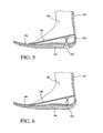
- a walker 160 includes a posterior shell 162, a plantar sole 166, an outsole 164, and an adjustable height insole 168.
- a pneumatic bladder 170 constructed of suitable materials capable of retaining a gas such as air therein, is provided between the plantar sole 166 and the insole 168.
- a valve mechanism 172 is provided at the posterior of the bladder 170 and protruding through an opening in the posterior shell 162 for access thereto by a practitioner. Any suitable valve mechanism, such as, for example a Schrader valve or a Presta valve, can be provided. It will be recognized that the valve mechanism 172 can alternatively be positioned to protrude through the plantar sole 166 and outsole 164.
- the patient can visit the practitioner, and the practitioner can release an appropriate amount of gas from the bladder 170, using the valve 172, in order to decrease the height of the insole 168 by an appropriate amount, for example, 1 mm.
- the walker 160 need not be removed from the patient in order to effectuate adjustment of the height of the insole 168. Similarly, a more even stretch of the Achilles tendon can be achieved, in order to avoid drastic changes in the stretched length of the tendon, which may lead to re-rupture of the tendon.
- a slow leak valve can be provided to automatically and continuously release a predefined amount of gas from the bladder 170 in order to automatically and gradually reduce the height of the insole 168, for example, an amount of 1 mm per week.
- a slow leak valve can be, for example, a slit valve designed to allow the slit to partially open in response to a continuous predefined pressure applied by the weight of the wearer of the walker 160.
- the slow leak valve can be any mechanical valve that can be set to an open or closed configuration, and which can be set in a slightly opened position to allow the slow leak.
- any suitable ball valve, disc valve, butterfly valve, etc. may be utilized as a slow leak valve.
- appropriate processor and automatic valve for example an electrically operated solenoid valve
- appropriate processor and automatic valve for example an electrically operated solenoid valve
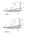
- a walker 180 includes a posterior shell 182, a plantar sole 186, an outsole 184, an adjustable height insole 188, and a bladder 192 having a valve 194.
- This variation of the Achilles tendon stretching device functions in generally the same manner as the device shown in Fig. 6 , with the exception that in addition to the bladder 192 positioned between the plantar sole 186 and the insole 188, removable and interchangeable heel wedges 190 having different heights are provided (one at a time) between the bladder 192 and the insole 188 and the plantar sole 186.
- multiple heel wedges of consistent heights can be provided in place of the interchangeable heel wedges 190.
- the height of the insole 188 would gradually decrease throughout a week, and when the patient visits the practitioner, the heel wedge 190 can be replaced with a heel wedge of lower height (or one of the multiple heel wedges can be removed) and the bladder 192 can be reinflated.
- pneumatic bladders and valves are disclosed, it is contemplated that hydraulic bladders and valves may also be used.
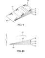
- FIG. 9 A fourth exemplary embodiment of an Achilles tendon stretching device in the form of a heel wedge 200 having layers 202, 204, 20, 208 which can be torn or cut off to adjust the height of the heel wedge is shown in Figs. 9 and 10 .
- the heel wedge 200 can be used in any orthopedic device for use with the foot, for example, walkers, diabetic walkers, post-op shoes, ankle braces, or any type of footwear, such as shoes or boots.
- the heel wedge 200 can be made from any suitable material, for example ethylene-vinyl acetate (EVA) foam. Further, the heel wedge 200 can be made from compression molded EVA foam. Exemplary EVA foam can have a density/hardness in the range of 35-60 shore. Another suitable material may be an artificial cork, such as an EVA cork mixture that is thermo moldable at approximately 120 to 140 degrees and results in a density/hardness of 50 shore. Another exemplary material may be polyurethane.
- EVA foam can have a density/hardness in the range of 35-60 shore.
- Another suitable material may be an artificial cork, such as an EVA cork mixture that is thermo moldable at approximately 120 to 140 degrees and results in a density/hardness of 50 shore.
- Another exemplary material may be polyurethane.
- the heel wedge 200 has a number of layers, all of which are integrally formed and connected together at an anterior portion of the heel wedge 200. As shown the heel wedge 200 includes first layer 202, second layer 204, third layer 206, and fourth layer 208. However, the number of layers shown is merely exemplary, and any suitable greater or lesser number of layers, for example ten to fifteen layers, may be used in order to achieve the desired amount and increments of height adjustment.
- the heel wedge 200 can be positioned within the heel portion of orthopedic device with all of the integrally formed layers thereof retained.
- the Achilles tendon of a user of the heel wedge 200 will be shortened to a first length.
- the layers 202, 204, 206, 208 thereof can be incrementally cut or torn from the heel wedge 200 in order to reduce the height of the heel wedge 200, thus stretching the Achilles tendon of the user to incrementally greater lengths.
- the thickness or height of the layers 202, 204, 206, 208 corresponds to the desired incremental stretch length of the Achilles tendon, and may be any desired thickness or height.
- the heel wedge 200 can be removed from the heel portion of orthopedic device. Then, the first layer 202 can be torn or cut away from the heel wedge 200, which can then be replaced in the heel portion of orthopedic device.
- Treatment can then occur for the desired length of time to stretch the Achilles tendon at the length that is provided by removing the first layer 202 of the heel wedge 200. This process can be repeated as necessary by removing subsequent layers 204, 206, 208 in succession to treat Achilles tendon injuries and surgical recovery with incremental stretching of the Achilles tendon.
- the adjacent first and second layers 202, 204 can be torn off of cut away in order to provide a greater height adjustment to increase the amount that the Achilles tendon is stretched.
- This process can allow the use of a heel wedge 200 having numerous layers of minimal thickness, for example 1 mm, for numerous treatment therapies for Achilles tendon injuries.
- Such a heel wedge and process can then be modified for each particular treatment protocol, where, for example one protocol requires an incremental height adjustment of 1 mm per week, and another treatment protocol requires an incremental height adjustment of 5 mm per week.
- heel wedge 200 only one type of heel wedge 200 need be manufactured in order to satisfy numerous treatment protocols.
- a heel stop 210 can be provided on the proximal surface 212 of the heel wedge 200.
- the heel stop 210 can be formed, for example, from a compression molded EVA foam, or can be an injected molded thermoplastic elastomer (TPE), or any other suitable material.
- TPE thermoplastic elastomer
- the heel stop 210 can have a generally triangular shape, with a raised ridge provided on a proximal surface thereof, such that the raised ridge provides a stop against forward migration of the user's heel during use.
- the heel stop 210 can have a generally trapezium or trapezoidal shape, such that a planar surface is provided at the raised ridge. The planar surface can thus provide an additional frictional surface to engage at least a portion of the arch of the user's foot in order to prevent slippage of the user's heel.
- the heel stop 210 can be glued or secured with adhesive directly to the proximal surface 212 of the heel wedge 200. Alternatively, the heel stop 210 may be held in place on the proximal surface 212 of the heel wedge 200 by the weight of the user and frictional forces.
- the heel wedge 200 having a number of layers, all of which are integrally formed and connected together at an anterior portion of the heel wedge 200, and which can be selectively removed as desired to achieve incremental height adjustment and stretching of the Achilles tendon provides a convenient and simple way to effect treatment and recovery for Achilles tendon injuries and surgeries.
- an Achilles tendon stretching device and components thereof can be made from any suitable materials.
- each of the adjustment mechanisms of the exemplary Achilles tendon stretching devices described herein can be variously located in any convenient location, for example, at the posterior of the walker or in the plantar sole region of the walker.
- any suitable mechanical, pneumatic, and/or hydraulic mechanism can be used to adjust the height of the insole.
- pneumatic or hydraulic cylinders and pistons may be positioned between the insoles and plantar soles and used to raise and lower the adjustable height insoles.
- a pneumatic or hydraulic cylinder and piston can be oriented to provide vertical translation to raise or lower the insole with respect to the plantar sole.
- Such pneumatic or hydraulic cylinders and pistons can be configured to automatically adjust height, either incrementally or continuously, as discussed in detail above with respect to alternatively recited configurations.
- the specific design and implementation of such pneumatic or hydraulic cylinders and pistons will be recognized by a person having skill the art.
Landscapes
- Health & Medical Sciences (AREA)
- Nursing (AREA)
- Orthopedic Medicine & Surgery (AREA)
- Engineering & Computer Science (AREA)
- Biomedical Technology (AREA)
- Heart & Thoracic Surgery (AREA)
- Vascular Medicine (AREA)
- Life Sciences & Earth Sciences (AREA)
- Animal Behavior & Ethology (AREA)
- General Health & Medical Sciences (AREA)
- Public Health (AREA)
- Veterinary Medicine (AREA)
- Orthopedics, Nursing, And Contraception (AREA)
Claims (15)
- Orthopädische Vorrichtung zur Verwendung als eine Achillessehnen-Dehnungsvorrichtung in einer Fußbekleidung, wobei die Vorrichtung die Fußbekleidung (100, 110, 120, 140, 160, 180) umfasst, dadurch gekennzeichnet, dass:die Fußbekleidung (100, 110, 120, 140, 160, 180) eine höheneinstellbare Einlegesohle (134, 148, 168, 188, 212) und eine Innensohle (132, 146, 166, 186) enthält, wobei ein manueller oder automatischer Höheneinstellmechanismus (126, 136, 150, 154, 170, 192, 200) vorgesehen ist, um graduell und/oder inkrementell die Höhe der Einlegesohle (134, 148, 168, 188, 212) bezüglich der Innensohle (126, 150, 154, 170, 192, 200) einzustellen.
- Orthopädische Vorrichtung nach Anspruch 1, wobei der Höheneinstellmechanismus umfasst:eine Einstellschraube (136) undeinen Einstellwähler (126).
- Orthopädische Vorrichtung nach Anspruch 2, wobei der Höheneinstellmechanismus des Weiteren umfasst:ein Hebemechanismus (138), der zwischen der Einlegesohle (134) und der Innensohle (132) positioniert ist, wobei eine Drehung des Einstellwählers (126) eine Drehung der Einstellschraube (136) bewirkt, um den Hebemechanismus (138) anzuheben oder abzusenken, um die Höhe der Einlegesohle (134) bezüglich der Innensohle (132) einzustellen.
- Orthopädische Vorrichtung nach Anspruch 2, wobei der Einstellwähler (126) oder die Fußbekleidung (120) eine Markierung (130) enthält, die auf eine eindeutige Anzeige (128) zeigt, die auf der Fußbekleidung (120) oder dem Einstellwähler (126) bereitgestellt ist, um eine inkrementelle Veränderung der Höhe der Einlegesohle (134) bezüglich der Innensohle (132) zu repräsentieren.
- Orthopädische Vorrichtung nach Anspruch 2, wobei der Einstellwähler (126) für eine manuelle Drehung eingerichtet ist, einschließlich Texturen oder Formen, um bei einer manuellen Manipulation desselben zu helfen, oder einen Elektromotor (133) und einen Steuermechanismus enthält, um eine automatische Einstellung des Einstellwählers (126) zu erlauben.
- Orthopädische Vorrichtung nach Anspruch 1, wobei die Fußbekleidung (120) einen eingebauten Elektronikmechanismus (135) enthält, um ein Aktivitätslevel eines Benutzers zu ermitteln und die Höhe der Einlegesohle (134) relativ zu der Innensohle (132) als Reaktion auf das ermittelte Aktivitätslevel automatisch einzustellen.
- Orthopädische Vorrichtung nach Anspruch 1, wobei die Fußbekleidung (120) einen eingebauten Kommunikationsmechanismus (135) enthält, der eingerichtet ist, zum Überwachen eines Fortschritts eines Trägers der orthopädischen Vorrichtung Nachrichten an einen Arzt bereitzustellen.
- Orthopädische Vorrichtung nach Anspruch 1, wobei der Höheneinstellmechanismus umfasst:eine Einstellschraube (150), welche durch die Innensohle (146) hindurch verläuft und mit der Einlegesohle (148) mittels eines Universalgelenks (152) verbunden ist, um eine Drehung der Einstellschraube (150) in eine vertikale Einstellung der Einlegesohle (148) bezüglich der Innensohle (146) zu übersetzen.
- Orthopädische Vorrichtung nach Anspruch 1, wobei der Höheneinstellmechanismus umfasst:eine zwischen der Einlegesohle (168) und der Innensohle (166) positionierte Blase (170), wobei die Blase (170) ein damit verbundenes Ventil (172) zum automatischen und/oder selektiven Ablassen von Gas oder Flüssigkeit daraus aufweist.
- Orthopädische Vorrichtung nach Anspruch 9, wobei das Ventil (172) ein langsam entweichendes Ventil ist, das eingerichtet ist, automatisch und kontinuierlich eine vordefinierte Menge von Gas oder Flüssigkeit aus der Blase (170) abzulassen.
- Orthopädische Vorrichtung nach Anspruch 9, des Weiteren umfassend:einen Prozessor undwobei das Ventil (172) ein von dem Prozessor gesteuertes Elektromagnetventil ist, um ein graduelles und/oder inkrementelles Ablassen von Gas oder Flüssigkeit aus der Blase (170) bereitzustellen.
- Orthopädische Vorrichtung nach Anspruch 9, des Weiteren umfassend:entfernbare und austauschbare Fersenkeile (190), die unterschiedliche Höhen aufweisen, bereitgestellt in Kombination mit der Blase (192), um die Höhe der Einlegesohle (188) bezüglich der Innensohle (186) einzustellen.
- Orthopädische Vorrichtung nach Anspruch 9, des Weiteren umfassend:entfernbare Fersenkeile (190), die einheitliche Höhen aufweisen, bereitgestellt in Kombination mit der Blase (192), um die Höhe der Einlegesohle (188) bezüglich der Innensohle (186) einzustellen.
- Orthopädische Vorrichtung nach Anspruch 1, wobei der Höheneinstellmechanismus umfasst:einen Fersenkeil (200), der eine Mehrzahl von integral gebildeten Schichten (202-208) aufweist, die an ihrem anterioren Teil verbunden sind,wobei eine proximale Oberfläche (212) des Fersenkeils (200) zumindest einen Teil der Einlegesohle bildet und die Schichten (202-208) des Fersenkeils (200) selektiv von dem Fersenkeil (200) entfernt werden können, um die Höhe der proximalen Oberfläche (212) des Fersenkeils (200) bezüglich der Innensohle einzustellen.
- Orthopädische Vorrichtung nach Anspruch 14, wobei der Fersenkeil (200) einen Fersenanschlag (210) enthält, der auf der proximalen Oberfläche (212) des Fersenkeils (200) bereitgestellt ist.
Applications Claiming Priority (3)
| Application Number | Priority Date | Filing Date | Title |
|---|---|---|---|
| US36056110P | 2010-07-01 | 2010-07-01 | |
| US201161453633P | 2011-03-17 | 2011-03-17 | |
| PCT/US2011/001168 WO2012003000A1 (en) | 2010-07-01 | 2011-07-01 | Achilles tendon stretching device |
Publications (2)
| Publication Number | Publication Date |
|---|---|
| EP2588043A1 EP2588043A1 (de) | 2013-05-08 |
| EP2588043B1 true EP2588043B1 (de) | 2015-02-25 |
Family
ID=45398603
Family Applications (1)
| Application Number | Title | Priority Date | Filing Date |
|---|---|---|---|
| EP11732530.8A Not-in-force EP2588043B1 (de) | 2010-07-01 | 2011-07-01 | Vorrichtung zur streckung der achillessehne |
Country Status (3)
| Country | Link |
|---|---|
| US (1) | US20120000092A1 (de) |
| EP (1) | EP2588043B1 (de) |
| WO (1) | WO2012003000A1 (de) |
Families Citing this family (34)
| Publication number | Priority date | Publication date | Assignee | Title |
|---|---|---|---|---|
| US10842653B2 (en) | 2007-09-19 | 2020-11-24 | Ability Dynamics, Llc | Vacuum system for a prosthetic foot |
| US9889034B2 (en) | 2010-07-01 | 2018-02-13 | Ossur Hf | Achilles tendon stretching device |
| US10863791B2 (en) | 2011-04-07 | 2020-12-15 | Ovation Medical | Removable leg walker |
| US20160302957A1 (en) * | 2011-04-07 | 2016-10-20 | Ortho Systems D/B/A Ovation Medical | Orthopedic walker boot having an outer sole formed from multiple materials |
| US8453351B1 (en) * | 2011-05-16 | 2013-06-04 | Allisa J. Hale | Shoe with a height-adjustable heel |
| US9198780B2 (en) | 2012-02-14 | 2015-12-01 | Ossur Hf | Vacuum assisted suspension system |
| WO2013165909A1 (en) | 2012-04-30 | 2013-11-07 | Ossur Hf | Prosthetic device, system and method for increasing vacuum attachment |
| US9248042B2 (en) | 2012-09-12 | 2016-02-02 | Yessenia Lopez | Dorsal foot splint |
| USD731070S1 (en) * | 2013-01-25 | 2015-06-02 | Vincent A. Benenati | Orthopedic walker |
| US9364348B2 (en) | 2013-03-01 | 2016-06-14 | Ossur Hf | Vacuum suspension system |
| US10085871B2 (en) | 2013-03-15 | 2018-10-02 | Ovation Systems | Overmolding for an orthopedic walking boot |
| US10449078B2 (en) | 2013-03-15 | 2019-10-22 | Ovation Medical | Modular system for an orthopedic walking boot |
| WO2014144517A1 (en) | 2013-03-15 | 2014-09-18 | Ovation Medical | Orthopedic walking boot with heel cushion |
| CN103238981A (zh) * | 2013-05-14 | 2013-08-14 | 温州职业技术学院 | 一种可调节鞋跟高度的鞋 |
| US9510965B2 (en) | 2014-07-01 | 2016-12-06 | Ortho Systems | Adjustable walking apparatus |
| US9757256B2 (en) | 2014-07-01 | 2017-09-12 | Ossur Hf | Pump mechanism for vacuum suspension system |
| EP3171830B1 (de) | 2014-07-21 | 2018-07-04 | Ossur Iceland EHF | Achillesfersenkeil |
| WO2016025371A1 (en) * | 2014-08-12 | 2016-02-18 | Ossur Hf | Achilles tendon stretching device |
| WO2016112030A1 (en) | 2015-01-08 | 2016-07-14 | Ossur Iceland Ehf | Pump mechanism |
| EP3297582B1 (de) | 2015-05-21 | 2019-04-17 | Ossur Iceland EHF | Pumpensystem |
| EP3302371B1 (de) | 2015-05-29 | 2024-10-16 | Ossur Iceland EHF | Pumpensystem zur verwendung mit einer prothetischen vorrichtung |
| WO2017034841A1 (en) | 2015-08-27 | 2017-03-02 | Ossur Iceland Ehf | Pump system |
| US10172414B2 (en) | 2016-08-02 | 2019-01-08 | Superfeet Worldwide, Inc. | Locking midsole and insole assembly |
| US10512554B2 (en) | 2016-08-26 | 2019-12-24 | Ossur Iceland Ehf | Pump system |
| JP7136772B2 (ja) * | 2016-11-09 | 2022-09-13 | ディージェーオー,エルエルシー | 機械的に調整可能な傾斜挿入体を有する整形外科用歩行ブーツ |
| USD846130S1 (en) | 2018-01-31 | 2019-04-16 | Ortho Systems | Knee brace |
| CN109198779A (zh) * | 2018-11-13 | 2019-01-15 | 温州职业技术学院 | 一种自动调整角度的检验用鞋 |
| CN111418915A (zh) * | 2020-04-07 | 2020-07-17 | 大连大杨创世服饰有限公司 | 一种纽扣可调式西服 |
| CN112841808B (zh) * | 2020-12-24 | 2022-06-17 | 和也健康科技有限公司 | 一种带有磁颗粒的健步按摩鞋 |
| CN112545104B (zh) * | 2020-12-30 | 2025-11-07 | 浙江荣企医疗科技有限公司 | 一种跟腱康复装置 |
| US20220279897A1 (en) * | 2021-03-04 | 2022-09-08 | Ramesh Arumugam | Height adjusting and stabilizing assembly for footwear |
| WO2023286071A1 (en) * | 2021-07-12 | 2023-01-19 | Prasannajeet Pramod Nikam | Wearable forearm gear for achilles tendon stretcher |
| US12558244B2 (en) * | 2022-11-29 | 2026-02-24 | Cleveland State University | Adjustability mechanism for lower limb orthosis |
| CN116942390B (zh) * | 2023-07-15 | 2025-11-18 | 中国人民解放军总医院第四医学中心 | 一种具有调平功能的跟腱靴 |
Family Cites Families (19)
| Publication number | Priority date | Publication date | Assignee | Title |
|---|---|---|---|---|
| US3124887A (en) * | 1964-03-17 | Height increasing devices for shoes | ||
| US1674687A (en) * | 1922-05-29 | 1928-06-26 | Loyd S Mccormick | Combination heel stop and cushion |
| US2184209A (en) * | 1939-04-17 | 1939-12-19 | Burger Joseph | Adjustable height increasing shoe |
| US2212414A (en) * | 1940-03-25 | 1940-08-20 | Burger Joseph | Adjustable height increasing shoe |
| US2509423A (en) * | 1947-12-11 | 1950-05-30 | Charlotte A Cramer | Wedge heel shoe |
| US2700230A (en) * | 1951-07-30 | 1955-01-25 | Herman A Beyer | Laminated foot elevator for shoes |
| US5464385A (en) | 1990-06-27 | 1995-11-07 | Royce Medical Company | Walker with open heel |
| US5078128A (en) | 1990-06-27 | 1992-01-07 | Royce Medical Company | Removable leg walker |
| DE4029120A1 (de) * | 1990-09-13 | 1992-03-19 | Habermeyer Peter | Vorrichtung zur umschliessenden fixierung von extremitaeten |
| US5437111A (en) * | 1992-03-13 | 1995-08-01 | Yuugen Kaisha Frontier | Elevating shoe provided with a deceptive inner member |
| US5329705A (en) | 1993-02-16 | 1994-07-19 | Royce Medical Company | Footgear with pressure relief zones |
| DE9314920U1 (de) * | 1993-10-01 | 1994-03-03 | Ott, Gerhard, Prof. Dr., 53177 Bonn | Fußentlastungsschiene |
| US5902259A (en) * | 1995-12-27 | 1999-05-11 | Wilkerson; Gary | Therapeutic ankle orthosis |
| US5732481A (en) * | 1996-06-10 | 1998-03-31 | Creative Labs, Inc. | Adjustable height insole system |
| US7303538B2 (en) | 2002-07-23 | 2007-12-04 | Ossur Hf | Versatile orthopaedic leg mounted walkers |
| USD483556S1 (en) * | 2002-10-28 | 2003-12-16 | Richard William Zehr | Orthotic heel insert |
| US7198610B2 (en) | 2004-12-22 | 2007-04-03 | Ossur Hf | Knee brace and method for securing the same |
| US8002724B2 (en) | 2008-05-15 | 2011-08-23 | Ossur Hf | Circumferential walker |
| US8313451B2 (en) * | 2008-09-17 | 2012-11-20 | Cox William J | Orthotic device with sliding mechanism |
-
2011
- 2011-06-30 US US13/173,496 patent/US20120000092A1/en not_active Abandoned
- 2011-07-01 WO PCT/US2011/001168 patent/WO2012003000A1/en not_active Ceased
- 2011-07-01 EP EP11732530.8A patent/EP2588043B1/de not_active Not-in-force
Also Published As
| Publication number | Publication date |
|---|---|
| WO2012003000A1 (en) | 2012-01-05 |
| EP2588043A1 (de) | 2013-05-08 |
| US20120000092A1 (en) | 2012-01-05 |
Similar Documents
| Publication | Publication Date | Title |
|---|---|---|
| US20120000092A1 (en) | Achilles tendon stretching device | |
| US9889034B2 (en) | Achilles tendon stretching device | |
| US11969373B2 (en) | Orthopedic device | |
| EP3049035B1 (de) | Orthopädische vorrichtung | |
| US9839548B2 (en) | Orthopedic device | |
| US9839549B2 (en) | Orthopedic device | |
| JP2024020525A (ja) | 支持装置 | |
| US5429588A (en) | Ankle foot orthoses known as lower leg walkers | |
| US9192504B2 (en) | Total contact cast | |
| US7743532B2 (en) | Walking boot for diabetic and other patients | |
| EP3171830B1 (de) | Achillesfersenkeil | |
| US7017218B2 (en) | Customized orthopedic sole-insert and method for making | |
| EP3193794B1 (de) | Achillessehnendehnungsvorrichtung | |
| Landsman et al. | Off-loading neuropathic wounds associated with diabetes using an ankle-foot orthosis | |
| US7291181B1 (en) | Stump boot for an ankle disarticulation patient | |
| KR100668534B1 (ko) | 양말형 기능성 깔창 | |
| EP2986260B1 (de) | Vollständig gegossener stützverband | |
| KR200405337Y1 (ko) | 발에 장착하는 기능성 깔창 |
Legal Events
| Date | Code | Title | Description |
|---|---|---|---|
| PUAI | Public reference made under article 153(3) epc to a published international application that has entered the european phase |
Free format text: ORIGINAL CODE: 0009012 |
|
| 17P | Request for examination filed |
Effective date: 20121218 |
|
| AK | Designated contracting states |
Kind code of ref document: A1 Designated state(s): AL AT BE BG CH CY CZ DE DK EE ES FI FR GB GR HR HU IE IS IT LI LT LU LV MC MK MT NL NO PL PT RO RS SE SI SK SM TR |
|
| DAX | Request for extension of the european patent (deleted) | ||
| GRAP | Despatch of communication of intention to grant a patent |
Free format text: ORIGINAL CODE: EPIDOSNIGR1 |
|
| INTG | Intention to grant announced |
Effective date: 20140922 |
|
| RIN1 | Information on inventor provided before grant (corrected) |
Inventor name: GUNNSTEINSSON, LARUS Inventor name: INGIMUNDARSON, ARNI, THOR Inventor name: KRISTJANSSON, ARNAR Inventor name: INGVARSSON, THORVALDUR Inventor name: EINARSSON, PALMI |
|
| GRAS | Grant fee paid |
Free format text: ORIGINAL CODE: EPIDOSNIGR3 |
|
| GRAA | (expected) grant |
Free format text: ORIGINAL CODE: 0009210 |
|
| AK | Designated contracting states |
Kind code of ref document: B1 Designated state(s): AL AT BE BG CH CY CZ DE DK EE ES FI FR GB GR HR HU IE IS IT LI LT LU LV MC MK MT NL NO PL PT RO RS SE SI SK SM TR |
|
| REG | Reference to a national code |
Ref country code: GB Ref legal event code: FG4D |
|
| REG | Reference to a national code |
Ref country code: CH Ref legal event code: EP |
|
| REG | Reference to a national code |
Ref country code: IE Ref legal event code: FG4D |
|
| REG | Reference to a national code |
Ref country code: DE Ref legal event code: R096 Ref document number: 602011014024 Country of ref document: DE Effective date: 20150409 |
|
| REG | Reference to a national code |
Ref country code: AT Ref legal event code: REF Ref document number: 711266 Country of ref document: AT Kind code of ref document: T Effective date: 20150415 |
|
| REG | Reference to a national code |
Ref country code: NL Ref legal event code: VDEP Effective date: 20150225 |
|
| REG | Reference to a national code |
Ref country code: AT Ref legal event code: MK05 Ref document number: 711266 Country of ref document: AT Kind code of ref document: T Effective date: 20150225 |
|
| REG | Reference to a national code |
Ref country code: LT Ref legal event code: MG4D |
|
| PG25 | Lapsed in a contracting state [announced via postgrant information from national office to epo] |
Ref country code: SE Free format text: LAPSE BECAUSE OF FAILURE TO SUBMIT A TRANSLATION OF THE DESCRIPTION OR TO PAY THE FEE WITHIN THE PRESCRIBED TIME-LIMIT Effective date: 20150225 Ref country code: HR Free format text: LAPSE BECAUSE OF FAILURE TO SUBMIT A TRANSLATION OF THE DESCRIPTION OR TO PAY THE FEE WITHIN THE PRESCRIBED TIME-LIMIT Effective date: 20150225 Ref country code: FI Free format text: LAPSE BECAUSE OF FAILURE TO SUBMIT A TRANSLATION OF THE DESCRIPTION OR TO PAY THE FEE WITHIN THE PRESCRIBED TIME-LIMIT Effective date: 20150225 Ref country code: NO Free format text: LAPSE BECAUSE OF FAILURE TO SUBMIT A TRANSLATION OF THE DESCRIPTION OR TO PAY THE FEE WITHIN THE PRESCRIBED TIME-LIMIT Effective date: 20150525 Ref country code: ES Free format text: LAPSE BECAUSE OF FAILURE TO SUBMIT A TRANSLATION OF THE DESCRIPTION OR TO PAY THE FEE WITHIN THE PRESCRIBED TIME-LIMIT Effective date: 20150225 Ref country code: LT Free format text: LAPSE BECAUSE OF FAILURE TO SUBMIT A TRANSLATION OF THE DESCRIPTION OR TO PAY THE FEE WITHIN THE PRESCRIBED TIME-LIMIT Effective date: 20150225 |
|
| PG25 | Lapsed in a contracting state [announced via postgrant information from national office to epo] |
Ref country code: LV Free format text: LAPSE BECAUSE OF FAILURE TO SUBMIT A TRANSLATION OF THE DESCRIPTION OR TO PAY THE FEE WITHIN THE PRESCRIBED TIME-LIMIT Effective date: 20150225 Ref country code: AT Free format text: LAPSE BECAUSE OF FAILURE TO SUBMIT A TRANSLATION OF THE DESCRIPTION OR TO PAY THE FEE WITHIN THE PRESCRIBED TIME-LIMIT Effective date: 20150225 Ref country code: GR Free format text: LAPSE BECAUSE OF FAILURE TO SUBMIT A TRANSLATION OF THE DESCRIPTION OR TO PAY THE FEE WITHIN THE PRESCRIBED TIME-LIMIT Effective date: 20150526 Ref country code: RS Free format text: LAPSE BECAUSE OF FAILURE TO SUBMIT A TRANSLATION OF THE DESCRIPTION OR TO PAY THE FEE WITHIN THE PRESCRIBED TIME-LIMIT Effective date: 20150225 |
|
| PG25 | Lapsed in a contracting state [announced via postgrant information from national office to epo] |
Ref country code: NL Free format text: LAPSE BECAUSE OF FAILURE TO SUBMIT A TRANSLATION OF THE DESCRIPTION OR TO PAY THE FEE WITHIN THE PRESCRIBED TIME-LIMIT Effective date: 20150225 |
|
| PG25 | Lapsed in a contracting state [announced via postgrant information from national office to epo] |
Ref country code: SK Free format text: LAPSE BECAUSE OF FAILURE TO SUBMIT A TRANSLATION OF THE DESCRIPTION OR TO PAY THE FEE WITHIN THE PRESCRIBED TIME-LIMIT Effective date: 20150225 Ref country code: CZ Free format text: LAPSE BECAUSE OF FAILURE TO SUBMIT A TRANSLATION OF THE DESCRIPTION OR TO PAY THE FEE WITHIN THE PRESCRIBED TIME-LIMIT Effective date: 20150225 Ref country code: DK Free format text: LAPSE BECAUSE OF FAILURE TO SUBMIT A TRANSLATION OF THE DESCRIPTION OR TO PAY THE FEE WITHIN THE PRESCRIBED TIME-LIMIT Effective date: 20150225 Ref country code: EE Free format text: LAPSE BECAUSE OF FAILURE TO SUBMIT A TRANSLATION OF THE DESCRIPTION OR TO PAY THE FEE WITHIN THE PRESCRIBED TIME-LIMIT Effective date: 20150225 Ref country code: RO Free format text: LAPSE BECAUSE OF FAILURE TO SUBMIT A TRANSLATION OF THE DESCRIPTION OR TO PAY THE FEE WITHIN THE PRESCRIBED TIME-LIMIT Effective date: 20150225 |
|
| REG | Reference to a national code |
Ref country code: DE Ref legal event code: R097 Ref document number: 602011014024 Country of ref document: DE |
|
| PG25 | Lapsed in a contracting state [announced via postgrant information from national office to epo] |
Ref country code: PL Free format text: LAPSE BECAUSE OF FAILURE TO SUBMIT A TRANSLATION OF THE DESCRIPTION OR TO PAY THE FEE WITHIN THE PRESCRIBED TIME-LIMIT Effective date: 20150225 |
|
| PG25 | Lapsed in a contracting state [announced via postgrant information from national office to epo] |
Ref country code: IT Free format text: LAPSE BECAUSE OF FAILURE TO SUBMIT A TRANSLATION OF THE DESCRIPTION OR TO PAY THE FEE WITHIN THE PRESCRIBED TIME-LIMIT Effective date: 20150225 |
|
| PLBE | No opposition filed within time limit |
Free format text: ORIGINAL CODE: 0009261 |
|
| STAA | Information on the status of an ep patent application or granted ep patent |
Free format text: STATUS: NO OPPOSITION FILED WITHIN TIME LIMIT |
|
| 26N | No opposition filed |
Effective date: 20151126 |
|
| PG25 | Lapsed in a contracting state [announced via postgrant information from national office to epo] |
Ref country code: SI Free format text: LAPSE BECAUSE OF FAILURE TO SUBMIT A TRANSLATION OF THE DESCRIPTION OR TO PAY THE FEE WITHIN THE PRESCRIBED TIME-LIMIT Effective date: 20150225 Ref country code: MC Free format text: LAPSE BECAUSE OF FAILURE TO SUBMIT A TRANSLATION OF THE DESCRIPTION OR TO PAY THE FEE WITHIN THE PRESCRIBED TIME-LIMIT Effective date: 20150225 |
|
| REG | Reference to a national code |
Ref country code: CH Ref legal event code: PL |
|
| PG25 | Lapsed in a contracting state [announced via postgrant information from national office to epo] |
Ref country code: LU Free format text: LAPSE BECAUSE OF FAILURE TO SUBMIT A TRANSLATION OF THE DESCRIPTION OR TO PAY THE FEE WITHIN THE PRESCRIBED TIME-LIMIT Effective date: 20150701 |
|
| REG | Reference to a national code |
Ref country code: IE Ref legal event code: MM4A |
|
| PG25 | Lapsed in a contracting state [announced via postgrant information from national office to epo] |
Ref country code: LI Free format text: LAPSE BECAUSE OF NON-PAYMENT OF DUE FEES Effective date: 20150731 Ref country code: CH Free format text: LAPSE BECAUSE OF NON-PAYMENT OF DUE FEES Effective date: 20150731 |
|
| PG25 | Lapsed in a contracting state [announced via postgrant information from national office to epo] |
Ref country code: BE Free format text: LAPSE BECAUSE OF FAILURE TO SUBMIT A TRANSLATION OF THE DESCRIPTION OR TO PAY THE FEE WITHIN THE PRESCRIBED TIME-LIMIT Effective date: 20150225 |
|
| REG | Reference to a national code |
Ref country code: FR Ref legal event code: PLFP Year of fee payment: 6 |
|
| PG25 | Lapsed in a contracting state [announced via postgrant information from national office to epo] |
Ref country code: IE Free format text: LAPSE BECAUSE OF NON-PAYMENT OF DUE FEES Effective date: 20150701 |
|
| PG25 | Lapsed in a contracting state [announced via postgrant information from national office to epo] |
Ref country code: MT Free format text: LAPSE BECAUSE OF FAILURE TO SUBMIT A TRANSLATION OF THE DESCRIPTION OR TO PAY THE FEE WITHIN THE PRESCRIBED TIME-LIMIT Effective date: 20150225 |
|
| PG25 | Lapsed in a contracting state [announced via postgrant information from national office to epo] |
Ref country code: HU Free format text: LAPSE BECAUSE OF FAILURE TO SUBMIT A TRANSLATION OF THE DESCRIPTION OR TO PAY THE FEE WITHIN THE PRESCRIBED TIME-LIMIT; INVALID AB INITIO Effective date: 20110701 Ref country code: SM Free format text: LAPSE BECAUSE OF FAILURE TO SUBMIT A TRANSLATION OF THE DESCRIPTION OR TO PAY THE FEE WITHIN THE PRESCRIBED TIME-LIMIT Effective date: 20150225 Ref country code: BG Free format text: LAPSE BECAUSE OF FAILURE TO SUBMIT A TRANSLATION OF THE DESCRIPTION OR TO PAY THE FEE WITHIN THE PRESCRIBED TIME-LIMIT Effective date: 20150225 |
|
| REG | Reference to a national code |
Ref country code: FR Ref legal event code: PLFP Year of fee payment: 7 |
|
| PG25 | Lapsed in a contracting state [announced via postgrant information from national office to epo] |
Ref country code: CY Free format text: LAPSE BECAUSE OF FAILURE TO SUBMIT A TRANSLATION OF THE DESCRIPTION OR TO PAY THE FEE WITHIN THE PRESCRIBED TIME-LIMIT Effective date: 20150225 |
|
| REG | Reference to a national code |
Ref country code: DE Ref legal event code: R082 Ref document number: 602011014024 Country of ref document: DE Representative=s name: KLUNKER IP PATENTANWAELTE PARTG MBB, DE |
|
| PG25 | Lapsed in a contracting state [announced via postgrant information from national office to epo] |
Ref country code: TR Free format text: LAPSE BECAUSE OF FAILURE TO SUBMIT A TRANSLATION OF THE DESCRIPTION OR TO PAY THE FEE WITHIN THE PRESCRIBED TIME-LIMIT Effective date: 20150225 |
|
| REG | Reference to a national code |
Ref country code: FR Ref legal event code: PLFP Year of fee payment: 8 |
|
| PG25 | Lapsed in a contracting state [announced via postgrant information from national office to epo] |
Ref country code: PT Free format text: LAPSE BECAUSE OF FAILURE TO SUBMIT A TRANSLATION OF THE DESCRIPTION OR TO PAY THE FEE WITHIN THE PRESCRIBED TIME-LIMIT Effective date: 20150225 Ref country code: MK Free format text: LAPSE BECAUSE OF FAILURE TO SUBMIT A TRANSLATION OF THE DESCRIPTION OR TO PAY THE FEE WITHIN THE PRESCRIBED TIME-LIMIT Effective date: 20150225 |
|
| PG25 | Lapsed in a contracting state [announced via postgrant information from national office to epo] |
Ref country code: AL Free format text: LAPSE BECAUSE OF FAILURE TO SUBMIT A TRANSLATION OF THE DESCRIPTION OR TO PAY THE FEE WITHIN THE PRESCRIBED TIME-LIMIT Effective date: 20150225 |
|
| PGFP | Annual fee paid to national office [announced via postgrant information from national office to epo] |
Ref country code: IS Payment date: 20190618 Year of fee payment: 9 |
|
| P01 | Opt-out of the competence of the unified patent court (upc) registered |
Effective date: 20230504 |
|
| PGFP | Annual fee paid to national office [announced via postgrant information from national office to epo] |
Ref country code: GB Payment date: 20230717 Year of fee payment: 13 |
|
| PGFP | Annual fee paid to national office [announced via postgrant information from national office to epo] |
Ref country code: FR Payment date: 20230724 Year of fee payment: 13 Ref country code: DE Payment date: 20230719 Year of fee payment: 13 |
|
| REG | Reference to a national code |
Ref country code: DE Ref legal event code: R119 Ref document number: 602011014024 Country of ref document: DE |
|
| GBPC | Gb: european patent ceased through non-payment of renewal fee |
Effective date: 20240701 |
|
| PG25 | Lapsed in a contracting state [announced via postgrant information from national office to epo] |
Ref country code: DE Free format text: LAPSE BECAUSE OF NON-PAYMENT OF DUE FEES Effective date: 20250201 |
|
| PG25 | Lapsed in a contracting state [announced via postgrant information from national office to epo] |
Ref country code: FR Free format text: LAPSE BECAUSE OF NON-PAYMENT OF DUE FEES Effective date: 20240731 |
|
| PG25 | Lapsed in a contracting state [announced via postgrant information from national office to epo] |
Ref country code: GB Free format text: LAPSE BECAUSE OF NON-PAYMENT OF DUE FEES Effective date: 20240701 |
|
| PG25 | Lapsed in a contracting state [announced via postgrant information from national office to epo] |
Ref country code: IS Free format text: LAPSE BECAUSE OF NON-PAYMENT OF DUE FEES Effective date: 20210205 |