EP2587819A2 - Contrôleur de synchronisation avec conversion de format vidéo, procédé associé et système d'affichage - Google Patents
Contrôleur de synchronisation avec conversion de format vidéo, procédé associé et système d'affichage Download PDFInfo
- Publication number
- EP2587819A2 EP2587819A2 EP12186797.2A EP12186797A EP2587819A2 EP 2587819 A2 EP2587819 A2 EP 2587819A2 EP 12186797 A EP12186797 A EP 12186797A EP 2587819 A2 EP2587819 A2 EP 2587819A2
- Authority
- EP
- European Patent Office
- Prior art keywords
- signal
- control
- display
- control signal
- output
- Prior art date
- Legal status (The legal status is an assumption and is not a legal conclusion. Google has not performed a legal analysis and makes no representation as to the accuracy of the status listed.)
- Withdrawn
Links
- 238000006243 chemical reaction Methods 0.000 title claims abstract description 71
- 238000000034 method Methods 0.000 title claims abstract description 16
- 238000010586 diagram Methods 0.000 description 6
- 238000005516 engineering process Methods 0.000 description 4
- 238000012856 packing Methods 0.000 description 4
- 238000012545 processing Methods 0.000 description 4
- 238000004519 manufacturing process Methods 0.000 description 3
- 230000005540 biological transmission Effects 0.000 description 2
- 230000008878 coupling Effects 0.000 description 2
- 238000010168 coupling process Methods 0.000 description 2
- 238000005859 coupling reaction Methods 0.000 description 2
- 230000000694 effects Effects 0.000 description 2
- 239000011521 glass Substances 0.000 description 2
- 238000012986 modification Methods 0.000 description 2
- 230000004048 modification Effects 0.000 description 2
- 230000011664 signaling Effects 0.000 description 2
- 238000013459 approach Methods 0.000 description 1
- 238000012937 correction Methods 0.000 description 1
- 238000013461 design Methods 0.000 description 1
- 230000010354 integration Effects 0.000 description 1
- 239000004973 liquid crystal related substance Substances 0.000 description 1
Images


Classifications
-
- G—PHYSICS
- G09—EDUCATION; CRYPTOGRAPHY; DISPLAY; ADVERTISING; SEALS
- G09G—ARRANGEMENTS OR CIRCUITS FOR CONTROL OF INDICATING DEVICES USING STATIC MEANS TO PRESENT VARIABLE INFORMATION
- G09G5/00—Control arrangements or circuits for visual indicators common to cathode-ray tube indicators and other visual indicators
- G09G5/003—Details of a display terminal, the details relating to the control arrangement of the display terminal and to the interfaces thereto
- G09G5/005—Adapting incoming signals to the display format of the display terminal
-
- H—ELECTRICITY
- H04—ELECTRIC COMMUNICATION TECHNIQUE
- H04N—PICTORIAL COMMUNICATION, e.g. TELEVISION
- H04N13/00—Stereoscopic video systems; Multi-view video systems; Details thereof
- H04N13/10—Processing, recording or transmission of stereoscopic or multi-view image signals
- H04N13/106—Processing image signals
- H04N13/139—Format conversion, e.g. of frame-rate or size
-
- H—ELECTRICITY
- H04—ELECTRIC COMMUNICATION TECHNIQUE
- H04N—PICTORIAL COMMUNICATION, e.g. TELEVISION
- H04N13/00—Stereoscopic video systems; Multi-view video systems; Details thereof
- H04N13/30—Image reproducers
- H04N13/356—Image reproducers having separate monoscopic and stereoscopic modes
-
- H—ELECTRICITY
- H04—ELECTRIC COMMUNICATION TECHNIQUE
- H04N—PICTORIAL COMMUNICATION, e.g. TELEVISION
- H04N13/00—Stereoscopic video systems; Multi-view video systems; Details thereof
- H04N13/30—Image reproducers
- H04N13/398—Synchronisation thereof; Control thereof
-
- G—PHYSICS
- G09—EDUCATION; CRYPTOGRAPHY; DISPLAY; ADVERTISING; SEALS
- G09G—ARRANGEMENTS OR CIRCUITS FOR CONTROL OF INDICATING DEVICES USING STATIC MEANS TO PRESENT VARIABLE INFORMATION
- G09G2320/00—Control of display operating conditions
- G09G2320/06—Adjustment of display parameters
- G09G2320/0613—The adjustment depending on the type of the information to be displayed
-
- G—PHYSICS
- G09—EDUCATION; CRYPTOGRAPHY; DISPLAY; ADVERTISING; SEALS
- G09G—ARRANGEMENTS OR CIRCUITS FOR CONTROL OF INDICATING DEVICES USING STATIC MEANS TO PRESENT VARIABLE INFORMATION
- G09G3/00—Control arrangements or circuits, of interest only in connection with visual indicators other than cathode-ray tubes
- G09G3/001—Control arrangements or circuits, of interest only in connection with visual indicators other than cathode-ray tubes using specific devices not provided for in groups G09G3/02 - G09G3/36, e.g. using an intermediate record carrier such as a film slide; Projection systems; Display of non-alphanumerical information, solely or in combination with alphanumerical information, e.g. digital display on projected diapositive as background
- G09G3/003—Control arrangements or circuits, of interest only in connection with visual indicators other than cathode-ray tubes using specific devices not provided for in groups G09G3/02 - G09G3/36, e.g. using an intermediate record carrier such as a film slide; Projection systems; Display of non-alphanumerical information, solely or in combination with alphanumerical information, e.g. digital display on projected diapositive as background to produce spatial visual effects
-
- G—PHYSICS
- G09—EDUCATION; CRYPTOGRAPHY; DISPLAY; ADVERTISING; SEALS
- G09G—ARRANGEMENTS OR CIRCUITS FOR CONTROL OF INDICATING DEVICES USING STATIC MEANS TO PRESENT VARIABLE INFORMATION
- G09G3/00—Control arrangements or circuits, of interest only in connection with visual indicators other than cathode-ray tubes
- G09G3/20—Control arrangements or circuits, of interest only in connection with visual indicators other than cathode-ray tubes for presentation of an assembly of a number of characters, e.g. a page, by composing the assembly by combination of individual elements arranged in a matrix no fixed position being assigned to or needed to be assigned to the individual characters or partial characters
- G09G3/34—Control arrangements or circuits, of interest only in connection with visual indicators other than cathode-ray tubes for presentation of an assembly of a number of characters, e.g. a page, by composing the assembly by combination of individual elements arranged in a matrix no fixed position being assigned to or needed to be assigned to the individual characters or partial characters by control of light from an independent source
- G09G3/36—Control arrangements or circuits, of interest only in connection with visual indicators other than cathode-ray tubes for presentation of an assembly of a number of characters, e.g. a page, by composing the assembly by combination of individual elements arranged in a matrix no fixed position being assigned to or needed to be assigned to the individual characters or partial characters by control of light from an independent source using liquid crystals
- G09G3/3611—Control of matrices with row and column drivers
Definitions
- the invention relates in general to a timing controller, and more particularly to a timing controller with video format conversion, a method therefor and a display system.
- a conventional liquid crystal display (LCD) system includes a system board and a timing control board.
- the system board is a front-end core of the display system and is extensively implemented in large-scale integrations.
- a main processing unit in the system board is a system-on-chip (SoC), which integrates various video interfaces including a high definition multimedia interface (HDMI), a video decoder and a scaler into an integrated chip serving as a core chip.
- SoC system-on-chip
- 3D display panels supporting the frame sequential format and line alternative format, respectively.
- two different system board circuits need to be provided in order to implement the two kinds of display systems utilizing the two types of 3D display panels.
- the overall display system structure is made complicated and inconvenient to manufacture such that the cost of the overall 3D display system is increased.
- the increased cost not only disfavors the manufacturing but also hinders the promotion and public acceptance of the 3D display system.
- the invention is directed to a timing controller with video format conversion, a method for a timing controller and a display system.
- a 3D display system can be implemented by using a timing controller with video format conversion according to an embodiment, thus reducing the complexity of the system circuit complexity of the display system.
- a timing control unit may be included in a control system for a display system having a two-dimensional (2D) display mode and a three-dimensional (3D) display mode.
- the timing control unit is for receiving a digital video signal, and outputting a 2D output video signal or a 3D output video signal, in response to a first control signal indicating the 2D display mode or the 3D display mode, wherein the first control signal included in a control signal.
- the timing control unit includes a 3D data format conversion unit, and outputs the 3D output video signal by the 3D data format conversion unit in response to the first control signal indicating the 3D display mode.
- a display system which may be included in or regarded as a control system, has a two-dimensional (2D) display mode and a three-dimensional (3D) display mode.
- the display system includes a display control unit and a timing control unit.
- the display control unit receives a video source, generates a digital video signal, and outputs a control signal.
- the control signal includes a first control signal indicating the 2D display mode or 3D display mode.
- the timing control unit coupled to the display control unit, receives the digital video signal and outputs a 2D output video signal or a 3D output video signal in response to the control signal.
- the timing control unit includes a 3D data format conversion unit, and outputs the 3D output video signal by the 3D data format conversion unit in response to the first control signal indicating the 3D display mode.
- a timing controller with video format conversion is provided.
- the timing controller is for use in a display panel having a 2D display mode and a 3D display mode.
- the timing controller includes an input signal switch unit and a 3D data format conversion unit.
- the input signal switch unit includes an input terminal, at least one first output terminal and at least one second output terminal.
- the first output terminal of the input signal switch unit is coupled to an output terminal of the timing controller.
- the 3D data format conversion unit is coupled between the at least one second output terminal of the input signal switch unit and the output terminal of the timing controller.
- the input signal switch unit receives a control signal.
- the control signal includes a first control signal indicating a 2D display mode or a 3D display mode.
- the input signal switch unit When the first control signal indicates the 2D display mode, the input signal switch unit outputs an input signal from the first output terminal. When the first control signal indicates the 3D display mode, the input signal switch unit outputs an input signal from the at least one second output terminal to the 3D data format conversion unit for display.
- the timing controller may be included in a control system for a display system having the 2D display mode and the 3D display mode.
- a timing control unit of a display includes the foregoing timing controller and a timing control module.
- the timing controller is disposed on the timing control module.
- the timing control module provides a timing control signal and a 3D output signal to a display panel.
- the timing control unit may be included in a control system for a display system having the 2D display mode and the 3D display mode.
- a method for a timing control unit includes the following steps.
- a control signal is received.
- the first control signal indicates a 2D display mode or a 3D display mode.
- a 2D output video signal or a 3D output video signal is outputted by a timing control unit.
- the timing control unit is coupled between a display panel module and a display control unit.
- the step of outputting the 2D or 3D output video signal includes the following steps. In response to the first control signal indicating the 2D display mode, a 2D output video signal is outputted; in response to the first control signal indicating the 3D display mode, a 3D output video signal is outputted by a 3D data format conversion unit according to the second control signal.
- FIG. 1 shows a block diagram of a display system utilizing a timing controller with data format conversion according to one embodiment.
- FIG. 2 is a block diagram of a timing controller according to one embodiment.
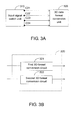
- FIG. 3A is a diagram illustrating a coupling relationship between an input signal switch unit and a 3D data format conversion unit.
- FIG. 3B is a block diagram of a coupling relationship of a 3D data format conversion unit according to one embodiment.
- FIG. 4 is a flowchart of a method for a timing control unit with 2D and 3D display modes according to one embodiment.
- a display system for a timing controller with video format conversion is provided.
- the timing controller receives an input signal having a source format, and outputs a 3D output video signal having a target format in response to a control signal.
- the timing controller is capable of receiving input signals of different source formats and outputting an output video signal compliant to a target format of a display module.
- a display control unit e.g., a system board serving as a video signal processing front end in a display panel, but not compliant to a target format required by 3D display of a 3D display panel, can employ the timing controller according to the embodiment to provide a 3D output video signal compliant to the target format to present 3D display effects by the 3D display panel.
- FIG. 1 shows a block diagram of a display system utilizing a timing controller with video format conversion according to one embodiment.
- a structure 100 of a 3D display system is provided according to this embodiment.
- a display system 10 e.g., a 3D LCD system based on a shutter glass or pattern retarder technology, such as a 3D LCD or television, has 2D and 3D modes and can be realized based on the structure 100 with the timing controller with video format conversion.
- the structure 100 includes a display control unit 110 and a timing control unit 120.
- the display control unit 110 receives a video source VS and generates a digital video signal V1, and outputs a control signal.
- the control signal includes a first control signal S1 and a second control signal S2.
- the first control signal S1 indicates a 2D display mode or a 3D display mode.
- the second control signal S2 indicates a format conversion request, e.g., indicating a request to convert a 3D video signal from one format to another format, indicating a source format of the digital video signal, or indicating a code representing a conversion request such as [1, 0] (i.e., converting to a target format of type 0 from a source format of type 1).
- the timing control unit 120 coupled to the display control unit 110, receives the digital video signal V1, and outputs a 2D or 3D output video signal in response to the control signal.
- the timing control unit 120 In response to the first control signal S1 indicating the 2D display mode, the timing control unit 120 outputs the 2D output video signal for 2D display.
- the timing control unit 120 is implemented for detecting the 2D display mode and the 3D display mode according to the first control signal S1.
- the timing control unit 120 converts low-voltage differential signaling (LVDS) pixel data provided by the display control unit 110 to a digital video signal, e.g., a mini-LVDS or reduce swing differential signaling (RSDS) signal to drive a data driver of a panel, so as to display a 2D picture on a display panel module 190, e.g., a 3D TFT-LCD panel.
- LVDS low-voltage differential signaling
- RSDS reduce swing differential signaling
- the timing control unit 120 In response to the first control signal S1 indicating the 3D display mode and the second control signal S2, the timing control unit 120 outputs a 3D output video signal V2 for display in the 3D display mode.
- the digital video signal V1 has a source format
- the 3D output video signal V2 has a target format.
- the timing control unit 120 performs 3D format conversion to convert the LVDS pixel data provided by the display control unit 110 to the digital video signal according to the second control signal S2, so as to display a 3D picture on the display panel module 190, e.g., a 3D TFT-LCD panel.
- the timing control unit 120 converts a source format to a target format.
- the source format is a side-by-side, top-down, or frame-packing 3D format.
- the target format is a frame sequential or line alternative 3D format.
- the timing control unit 120 includes a 3D data format conversion unit (as shown in FIG. 2 ).
- the timing control unit 120 outputs a 3D output video signal by the 3D data format conversion unit.
- the 3D data format conversion unit converts a digital video signal to a 3D output video signal having a target format supported by the display panel module.
- the display system 10 implementing the structure 100 can reduce system circuit complexity.
- a 3D LCD system such as a 3D LCD or television based on a shutter glass or pattern retarder technology
- the display system 10 implementing the structure 100 can reduce system circuit complexity.
- the timing control unit 120 of the display in FIG. 1 may be implemented to include a timing control module and a timing controller.
- the timing controller with video format conversion is implemented as an integrated circuit.
- the timing control module may be implemented as a circuit board, e.g., a TCON board.
- the timing controller may be disposed on the timing control module to provide a timing control signal and a 2D or 3D output video signal to the display panel module 190.
- the timing control unit 120 is substantially an interface for video transmission and control between the display control unit 110 and the display panel module 190.
- the timing control unit 120 can include other circuits for driving the display panel 190, e.g., a gamma correction element or a power component.
- a person skilled in the related art can implement the display panel 190 according to actual requirements and thus the implementation is not limiting to the above examples.
- FIG. 2 shows a block diagram of a timing controller according to one embodiment.
- a timing controller 200 includes an input signal switch unit 210 and a 3D data format conversion unit 220.
- the input signal switch unit 210 has an input terminal N1, at least one first output terminal C1 and at least one second output terminal C2.
- the first output terminal C1 of the input signal switch unit 210 is coupled to an output terminal OUT of the timing controller 200.
- the 3D data format conversion unit 220 is coupled between the second output terminal C2 of the input signal switch unit 210 and the output terminal OUT of the timing controller 200.
- a first control signal S1 indicates a 2D display mode
- the input signal switch unit 210 outputs an input signal V1 from the first output terminal C1.
- the input signal switch unit 210 When a first control signal S1 indicates a 3D display mode, the input signal switch unit 210 outputs the input signal V1 from one of the at least one second output terminal C2, and the 3D data format conversion unit 220 provides a 3D output video signal for 3D display.
- the input signal switch unit 210 receives a control signal, wherein the control signal includes a first control signal indicating a 2D display mode or a 3D display mode.
- the input signal switch unit 210 outputs the input signal from the at least one second output terminal C2 to the 3D data format conversion unit 220.
- the control signal further includes a second control signal.
- the input signal switch unit 210 outputs the input signal from one of the at least one second output terminal C2 according to the second control signal.
- the number of the second output terminal C2 of the input signal switch unit 210 may be one or multiple.
- the at least one second output terminal C2 of the input signal switch unit 210 may be coupled to the 3D data format conversion unit 220 to output the output video signal for 3D format conversion in the 3D display mode.
- the input signal switch unit 210 when the first control signal S1 indicates the 3D display mode, the input signal switch unit 210 outputs the input signal V1 from a corresponding one of a plurality of second output terminals, e.g., C21, C22, C23 and C24, wherein the corresponding one is the second output terminal corresponding to a format conversion request (e.g., indicated by the second control signal S2).
- a format conversion request e.g., indicated by the second control signal S2
- multiple data channels exist between an input signal switch unit 310 and a 3D data format conversion unit 320, and each of the channels corresponds to a format conversion processing.
- the 3D data format conversion unit 320 includes a first 3D format conversion circuit 321 and a second 3D format conversion circuit 322.
- the first 3D format conversion circuit 321 coupled to one of a plurality of second output terminals, receives an input signal having a first source format (e.g., a side-by-side format) and outputs an output signal having a first target format as a 3D output signal V2, e.g., for a display apparatus supporting 3D display in the first target format (e.g., a frame sequential format).
- a first source format e.g., a side-by-side format
- V2 e.g., for a display apparatus supporting 3D display in the first target format (e.g., a frame sequential format).
- the second 3D format conversion circuit 322 coupled to another one of the second output terminals, receives an input signal having a second source format (e.g., a top-down format) and outputs an output signal having the first target format as the 3D output signal V2.
- the 3D format conversion circuit is implemented according to format requirements of the source format and the target format.
- the source format is a side-by-side format requiring 1080i@50/60Hz
- the target format is a frame sequential format.
- a frame sequential signal transmits a full-resolution picture at a speed of 120 frames per second, with the frames alternating one another.
- the display apparatus sequentially receives a left-eye frame, a right-eye frame, a left-eye frame, a right-eye frame, and so forth. Therefore, the 3D format conversion circuits may be implemented by circuit hardware or a programmable processor according to format principles and requirements.
- the 3D data format conversion unit is implemented to convert an input signal having a source format of a side-by-side format, a top-down format, a frame packing format or a line alternative format to an output video signal having a target format of a frame sequential format.
- the target format is a 3D frame sequential format
- the frame refresh rate (e.g., 120Hz) of the 3D output signal is at least twice of the frame refresh rate of an input signal.
- the 3D data format conversion unit is implemented to convert an input signal having a source format such as a side-by-side format, a top-down format, a frame packing format or a line alternative format to an output video signal having a target format of a line alternative format.
- the 3D data format conversion unit is implemented to cover both embodiments above to provide an output video signal having a target format as a line alternative format or a frame sequential format.
- the input signal switch unit 210 in FIG. 1 can be realized to have one second output terminal C2.
- the 3D data format conversion unit 220 may be implemented as shown in FIG. 3B , including an additional circuit for video signal switch to perform switching for conversion according to the second control signal.
- an output terminal (or an input terminal) of the input signal switch unit may also represent a parallel or serial channel, and is not limited to that shown in the drawings.
- the timing controller 200 includes a control unit 230 for receiving a control signal so as to perform mode control and format conversion.
- the control unit 230 coupled to the input signal switch unit 210, informs or enables the input signal switch unit 210 to output the input signal V1 from the first output terminal C1 in response to a control signal (e.g., the first control signal S1) indicating the 2D display mode. Also in response to the control signal (e.g., the first control signal S1) indicating the 3D display mode, the control unit 230 informs or enables the input signal switch unit 210 to output the input signal V1 from at least one of the second output terminals C2.
- a control signal e.g., the first control signal S1 indicating the 2D display mode
- the control unit 230 informs or enables the input signal switch unit 210 to output the input signal V1 from at least one of the second output terminals C2.
- the control unit 230 includes a mode control interface 231 and a format control interface 240.
- the mode control interface 231 receives a control signal (e.g., the first control signal S1) and informs the input signal switch unit 231 to enter either the 2D or 3D display mode.
- the mode control interface 231 informs or activates the format control interface 240.
- the format control interface 240 receives a control signal (e.g., the second control signal S2) and informs the input signal switch unit 210 to perform the switching of a desired format.
- the format control interface 240 further manages data transmission and conversion between the format control interface 240 and the display control unit 110.
- the format control interface 240 includes a digital interface 241 and a decoder 243.
- the digital interface 241 is implemented by a hardware interface supporting a digital interface protocol, e.g., 12C and SPI.
- the decoder 243 decodes the control signal received by the digital interface 241 into data, a request or a command to inform the input signal switch unit 210 to perform 3D format conversion.
- the above protocol may also be various types of definition. For example, 2-bit, 4-bit or other data formats are utilized for defining the format conversion.
- 0001, 0010, 0011 and 0100 respectively represent source formats of a side-by-side format, a top-down format, a frame packing format and a line alternative format; 1000 and 1001 respectively represent target formats of a frame sequential format and a line alternative format.
- the control unit 230 may be implemented according to setting and circuit requirements, and other definitions may be used instead of the examples above.
- the first control signal S1 and the second control signal S2 may be regarded as a control signal or integrated in a control signal.
- the input signal switch unit 210 may directly receive a control signal rather than through an additional control unit.
- a same digital interface e.g., 12C or SPI
- the timing controller 200 further includes an input interface 280 and an output interface 290 for complying with an input/output interface requirements of a front-end of rear-end circuit of the timing controller 200.
- the input interface 280 is compliant to an LVSD interface
- the output interface 290 is compliant to a mini-LVDS/RSDS interface to drive the data driver of the panel.
- control signal (e.g., S1 or S2) can be embedded in a signal stream of the input signal V1 of the input signal switch unit 210, e.g., the control signal is embedded as a header in a signal stream of the input signal V1.
- the timing control unit 120, the input signal switch unit 210 or the 3D data format conversion unit 220 can be implemented by a processor, a digital signal processor, or a programmable integrated circuit such as a microcontroller, a field programmable gate array (FPGA) or an application specific integrated circuit (ASIC). Further in an example, the timing control unit 120 can be integrated as an integrated circuit or integrated with other circuits into a system on chip.
- a processor a digital signal processor
- a programmable integrated circuit such as a microcontroller, a field programmable gate array (FPGA) or an application specific integrated circuit (ASIC).
- FPGA field programmable gate array
- ASIC application specific integrated circuit
- the timing control unit can be included in a control system for a display system having the 2D and 3D display modes.
- the timing control unit is for receiving a digital video signal, and outputting a 2D output video signal or a 3D output video signal, in response to a first control signal indicating the 2D display mode or the 3D display mode, wherein the first control signal included in a control signal.
- the timing control unit includes a 3D data format conversion unit (such as one as illustrated above), and outputs the 3D output video signal by the 3D data format conversion unit in response to the first control signal indicating the 3D display mode.
- the timing control unit can further include one or more other components, such as the one or more components, units, interfaces in various embodiments according to FIG. 2 , 3A, or 3B .
- the timing control unit may also be implemented as an integrated circuit.
- the structure 100 or the display system 10, such as illustrated in FIG. 1 may be included in (or regarded as) a control system having the 2D and 3D display modes.
- FIG. 4 shows a flowchart of a method for a timing control unit with the 2D and 3D display modes according to one embodiment.
- the method includes the steps below.
- a control signal is received.
- the control signal includes a first control signal and a second control signal.
- the first control signal indicates a 2D display mode or a 3D display mode, i.e., a digital video signal is a 2D or 3D display mode signal.
- the second control signal is a source format of the digital video signal.
- a 2D output video signal or a 3D output video signal is outputted by a timing control unit.
- the timing control unit is coupled between a display panel module and a display control unit.
- Step S430 includes steps S431 to S435.
- step S431 it is determined whether the control signal indicates the 2D mode or the 3D mode.
- step S433 it is determined whether the control signal indicates the 2D mode.
- step S433 a 2D output video signal is outputted in response to the first control signal indicating the 2D display mode, e.g., the 2D output video signal is outputted to a display panel module.
- step S435 is performed.
- step S435 in response to the first control signal indicating the 3D display mode, a 3D data format conversion is performed to output a 3D output video signal according to the second control signal, e.g., outputting the 3D output video signal by a 3D data format conversion unit.
- the 3D data format conversion unit converts a digital video signal to a 3D output video signal having a target format supported by the display panel module.
- the control signal when the first control signal indicates the 3D display mode, the control signal further includes the second control signal indicating the source format. In another embodiment, the first control signal indicates the 2D display mode, and the second control signal needs not indicate the source format.
- the target format is a frame sequential format, a line alternative format, or another format.
- the format conversion request may indicate a first source format.
- Embodiments of the target format and the source format may be referred in the description of the foregoing embodiments, and shall be omitted herein.
- a timing controller, a method for a timing controller and a display system are as described above.
- a timing controller with video format conversion is provided according to one embodiment.
- implementation of a 3D display system by using the timing controller can reduce system circuit complexity.
- a display control unit e.g., a system board
- a display control unit serving as a video signal processing front end in a display panel, but not compliant to a target format required by 3D display of a 3D display panel, can utilize the timing controller according to the embodiment to provide a 3D output video signal compliant to the target format to present 3D display effects by the 3D display panel.
- the circuit complexity of the system board is reduced to simplify the overall system structure. More specifically, even a conventional system board (e.g., a conventional SoC) that cannot directly support 3D video signals or data format conversion is still capable of controlling a timing controller with video format conversion, thereby providing an output video signal compliant to a 3D display panel for display. Such an approach will be of great convenience to the manufacturing of 3D display systems, thus resulting in reduced hardware costs.
- a conventional system board e.g., a conventional SoC
Landscapes
- Engineering & Computer Science (AREA)
- Multimedia (AREA)
- Signal Processing (AREA)
- Physics & Mathematics (AREA)
- Computer Hardware Design (AREA)
- General Physics & Mathematics (AREA)
- Theoretical Computer Science (AREA)
- Testing, Inspecting, Measuring Of Stereoscopic Televisions And Televisions (AREA)
- Controls And Circuits For Display Device (AREA)
- Control Of Indicators Other Than Cathode Ray Tubes (AREA)
- Liquid Crystal Display Device Control (AREA)
- Liquid Crystal (AREA)
Applications Claiming Priority (1)
| Application Number | Priority Date | Filing Date | Title |
|---|---|---|---|
| TW100139656A TWI514844B (zh) | 2011-10-31 | 2011-10-31 | 具有視訊格式轉換的時序控制裝置、時序控制裝置的方法以及其顯示系統 |
Publications (2)
| Publication Number | Publication Date |
|---|---|
| EP2587819A2 true EP2587819A2 (fr) | 2013-05-01 |
| EP2587819A3 EP2587819A3 (fr) | 2013-12-04 |
Family
ID=47325800
Family Applications (1)
| Application Number | Title | Priority Date | Filing Date |
|---|---|---|---|
| EP12186797.2A Withdrawn EP2587819A3 (fr) | 2011-10-31 | 2012-10-01 | Contrôleur de synchronisation avec conversion de format vidéo, procédé associé et système d'affichage |
Country Status (4)
| Country | Link |
|---|---|
| US (1) | US20130106996A1 (fr) |
| EP (1) | EP2587819A3 (fr) |
| JP (1) | JP2013097379A (fr) |
| TW (1) | TWI514844B (fr) |
Cited By (2)
| Publication number | Priority date | Publication date | Assignee | Title |
|---|---|---|---|---|
| CN109559670A (zh) * | 2018-10-31 | 2019-04-02 | 惠科股份有限公司 | 一种显示面板的数据处理方法和显示装置 |
| CN116743952A (zh) * | 2023-08-11 | 2023-09-12 | 杭州灵伴科技有限公司 | 主机设备、头戴式显示设备和数据传输方法 |
Families Citing this family (5)
| Publication number | Priority date | Publication date | Assignee | Title |
|---|---|---|---|---|
| TW201419831A (zh) * | 2012-11-13 | 2014-05-16 | Realtek Semiconductor Corp | 立體影像格式轉換器及其立體影像格式轉換方法 |
| JP2015079173A (ja) * | 2013-10-18 | 2015-04-23 | セイコーエプソン株式会社 | 電気光学装置、電気光学装置の駆動方法及び電子機器 |
| CN103794172B (zh) * | 2014-01-22 | 2016-03-09 | 北京京东方显示技术有限公司 | 一种接口转换电路、显示面板驱动方法和显示装置 |
| WO2016080066A1 (fr) * | 2014-11-21 | 2016-05-26 | 富士フイルム株式会社 | Dispositif de commande d'affichage de données de série temporelle, procédé et programme de fonctionnement de celui-ci, et système |
| CN105450965B (zh) * | 2015-12-09 | 2019-07-19 | 北京小鸟看看科技有限公司 | 一种视频转换方法、装置和系统 |
Citations (1)
| Publication number | Priority date | Publication date | Assignee | Title |
|---|---|---|---|---|
| US20100053306A1 (en) * | 2008-09-02 | 2010-03-04 | Yasutaka Hirasawa | Image Processing Apparatus, Image Processing Method, and Program |
Family Cites Families (7)
| Publication number | Priority date | Publication date | Assignee | Title |
|---|---|---|---|---|
| JP4364287B1 (ja) * | 2008-06-27 | 2009-11-11 | 株式会社東芝 | 映像信号処理装置及びテレビジョン受信装置及びその制御方法 |
| JP4606502B2 (ja) * | 2008-08-07 | 2011-01-05 | 三菱電機株式会社 | 画像表示装置および方法 |
| JP2010169777A (ja) * | 2009-01-21 | 2010-08-05 | Sony Corp | 画像処理装置、画像処理方法およびプログラム |
| CN102356638A (zh) * | 2009-03-16 | 2012-02-15 | Lg电子株式会社 | 显示三维图像数据的方法和处理三维图像数据的设备 |
| JP5702063B2 (ja) * | 2009-12-14 | 2015-04-15 | ソニー株式会社 | 表示装置、表示方法及びコンピュータプログラム |
| US9491432B2 (en) * | 2010-01-27 | 2016-11-08 | Mediatek Inc. | Video processing apparatus for generating video output satisfying display capability of display device according to video input and related method thereof |
| WO2011121916A1 (fr) * | 2010-03-29 | 2011-10-06 | パナソニック株式会社 | Dispositif de traitement vidéo |
-
2011
- 2011-10-31 TW TW100139656A patent/TWI514844B/zh not_active IP Right Cessation
-
2012
- 2012-09-07 US US13/606,492 patent/US20130106996A1/en not_active Abandoned
- 2012-10-01 EP EP12186797.2A patent/EP2587819A3/fr not_active Withdrawn
- 2012-10-09 JP JP2012223965A patent/JP2013097379A/ja active Pending
Patent Citations (1)
| Publication number | Priority date | Publication date | Assignee | Title |
|---|---|---|---|---|
| US20100053306A1 (en) * | 2008-09-02 | 2010-03-04 | Yasutaka Hirasawa | Image Processing Apparatus, Image Processing Method, and Program |
Non-Patent Citations (1)
| Title |
|---|
| HIMAX TECHNOLOGIES ET AL: "Himax Unveils Industry-Leading 3D Timing Controller for Naked-Eye 3D Panels", 13 June 2011 (2011-06-13), XP055394459, Retrieved from the Internet <URL:https://globenewswire.com/news-release/2011/06/13/449251/224220/en/Himax-Unveils-Industry-Leading-3D-Timing-Controller-for-Naked-Eye-3D-Panels.html> [retrieved on 20170727] * |
Cited By (3)
| Publication number | Priority date | Publication date | Assignee | Title |
|---|---|---|---|---|
| CN109559670A (zh) * | 2018-10-31 | 2019-04-02 | 惠科股份有限公司 | 一种显示面板的数据处理方法和显示装置 |
| CN116743952A (zh) * | 2023-08-11 | 2023-09-12 | 杭州灵伴科技有限公司 | 主机设备、头戴式显示设备和数据传输方法 |
| CN116743952B (zh) * | 2023-08-11 | 2024-04-30 | 杭州灵伴科技有限公司 | 主机设备、头戴式显示设备和数据传输方法 |
Also Published As
| Publication number | Publication date |
|---|---|
| US20130106996A1 (en) | 2013-05-02 |
| TW201318409A (zh) | 2013-05-01 |
| JP2013097379A (ja) | 2013-05-20 |
| TWI514844B (zh) | 2015-12-21 |
| EP2587819A3 (fr) | 2013-12-04 |
Similar Documents
| Publication | Publication Date | Title |
|---|---|---|
| EP2587819A2 (fr) | Contrôleur de synchronisation avec conversion de format vidéo, procédé associé et système d'affichage | |
| US8957834B2 (en) | Timing controller with frequency modulation, converter with frequency modulation for scanning-based backlight unit module, and control system for 3D display | |
| US20110149032A1 (en) | Transmission and handling of three-dimensional video content | |
| US10447964B2 (en) | Interface conversion circuit, display panel driving method and display apparatus | |
| CN103347163A (zh) | 一种超高清视频图像处理和传送的系统及其方法 | |
| CN107665105B (zh) | 显示设备接口转换装置、多屏显示系统及多屏显示方法 | |
| US9813697B2 (en) | Head mount display and display control method | |
| US20150279312A1 (en) | Lcd panel driving circuit, lcd device, and driving method | |
| US7880713B2 (en) | Method of increasing efficiency of video display and related apparatus | |
| CN101923843A (zh) | 一种实现视频信号冗余备份的系统及方法 | |
| US20130187832A1 (en) | Display apparatus and method for controlling the same | |
| US20120019639A1 (en) | Active shutter stereoscopic image display system and method of controlling the same | |
| US11936927B2 (en) | Transmission control system of multi-media signal, transmitter control circuit and receiver control circuit | |
| CN114267293B (zh) | 显示装置及其显示方法 | |
| KR20130093432A (ko) | 구동 장치, 이를 포함하는 표시 장치 및 그 구동 방법 | |
| EP3169067A1 (fr) | Système et procédé de traitement d'affichage et dispositif électronique | |
| US20140368520A1 (en) | Frame rate converter and timing controller | |
| US20120127159A1 (en) | Method of driving display panel and display apparatus for performing the same | |
| JP2012244625A (ja) | 適応型タイミングコントローラ及びその駆動方法 | |
| CN103093716B (zh) | 时序控制装置、时序控制装置的方法以及显示系统 | |
| US20120154374A1 (en) | 3d image conversion system | |
| CN102857777B (zh) | 一种平面显示器及其显示控制方法 | |
| KR101296815B1 (ko) | 디지털 방송용 디스플레이 보드 | |
| KR102043489B1 (ko) | 액정 디스플레이의 구동 장치, 구동 방법, 및 대응하는 액정 디스플레이 | |
| US20110210967A1 (en) | Image processing device, projector, and image processing method |
Legal Events
| Date | Code | Title | Description |
|---|---|---|---|
| PUAI | Public reference made under article 153(3) epc to a published international application that has entered the european phase |
Free format text: ORIGINAL CODE: 0009012 |
|
| AK | Designated contracting states |
Kind code of ref document: A2 Designated state(s): AL AT BE BG CH CY CZ DE DK EE ES FI FR GB GR HR HU IE IS IT LI LT LU LV MC MK MT NL NO PL PT RO RS SE SI SK SM TR |
|
| AX | Request for extension of the european patent |
Extension state: BA ME |
|
| PUAL | Search report despatched |
Free format text: ORIGINAL CODE: 0009013 |
|
| AK | Designated contracting states |
Kind code of ref document: A3 Designated state(s): AL AT BE BG CH CY CZ DE DK EE ES FI FR GB GR HR HU IE IS IT LI LT LU LV MC MK MT NL NO PL PT RO RS SE SI SK SM TR |
|
| AX | Request for extension of the european patent |
Extension state: BA ME |
|
| RIC1 | Information provided on ipc code assigned before grant |
Ipc: H04N 13/00 20060101AFI20131031BHEP |
|
| 17P | Request for examination filed |
Effective date: 20140604 |
|
| RBV | Designated contracting states (corrected) |
Designated state(s): AL AT BE BG CH CY CZ DE DK EE ES FI FR GB GR HR HU IE IS IT LI LT LU LV MC MK MT NL NO PL PT RO RS SE SI SK SM TR |
|
| 17Q | First examination report despatched |
Effective date: 20151118 |
|
| STAA | Information on the status of an ep patent application or granted ep patent |
Free format text: STATUS: THE APPLICATION HAS BEEN WITHDRAWN |
|
| 18W | Application withdrawn |
Effective date: 20180215 |