EP2587658A2 - Series-connected multi-level power conversion device - Google Patents
Series-connected multi-level power conversion device Download PDFInfo
- Publication number
- EP2587658A2 EP2587658A2 EP12179687.4A EP12179687A EP2587658A2 EP 2587658 A2 EP2587658 A2 EP 2587658A2 EP 12179687 A EP12179687 A EP 12179687A EP 2587658 A2 EP2587658 A2 EP 2587658A2
- Authority
- EP
- European Patent Office
- Prior art keywords
- phase
- winding
- voltage
- current
- secondary windings
- Prior art date
- Legal status (The legal status is an assumption and is not a legal conclusion. Google has not performed a legal analysis and makes no representation as to the accuracy of the status listed.)
- Granted
Links
- 238000006243 chemical reaction Methods 0.000 title claims abstract description 46
- 238000004804 winding Methods 0.000 claims abstract description 368
- 239000013598 vector Substances 0.000 description 105
- 230000018199 S phase Effects 0.000 description 35
- 238000010586 diagram Methods 0.000 description 27
- 238000009499 grossing Methods 0.000 description 16
- XEEYBQQBJWHFJM-UHFFFAOYSA-N Iron Chemical group [Fe] XEEYBQQBJWHFJM-UHFFFAOYSA-N 0.000 description 14
- 238000009413 insulation Methods 0.000 description 9
- 229910001219 R-phase Inorganic materials 0.000 description 7
- 239000003990 capacitor Substances 0.000 description 4
- 229910052720 vanadium Inorganic materials 0.000 description 3
- 230000003111 delayed effect Effects 0.000 description 2
- 238000005516 engineering process Methods 0.000 description 2
- 230000004907 flux Effects 0.000 description 2
- 238000000034 method Methods 0.000 description 2
- 230000007935 neutral effect Effects 0.000 description 2
- 241001676573 Minium Species 0.000 description 1
- 239000004065 semiconductor Substances 0.000 description 1
- 229910052715 tantalum Inorganic materials 0.000 description 1
Images


Classifications
-
- H—ELECTRICITY
- H02—GENERATION; CONVERSION OR DISTRIBUTION OF ELECTRIC POWER
- H02M—APPARATUS FOR CONVERSION BETWEEN AC AND AC, BETWEEN AC AND DC, OR BETWEEN DC AND DC, AND FOR USE WITH MAINS OR SIMILAR POWER SUPPLY SYSTEMS; CONVERSION OF DC OR AC INPUT POWER INTO SURGE OUTPUT POWER; CONTROL OR REGULATION THEREOF
- H02M7/00—Conversion of ac power input into dc power output; Conversion of dc power input into ac power output
- H02M7/42—Conversion of dc power input into ac power output without possibility of reversal
- H02M7/44—Conversion of dc power input into ac power output without possibility of reversal by static converters
- H02M7/48—Conversion of dc power input into ac power output without possibility of reversal by static converters using discharge tubes with control electrode or semiconductor devices with control electrode
- H02M7/497—Conversion of dc power input into ac power output without possibility of reversal by static converters using discharge tubes with control electrode or semiconductor devices with control electrode sinusoidal output voltages being obtained by combination of several voltages being out of phase
-
- H—ELECTRICITY
- H02—GENERATION; CONVERSION OR DISTRIBUTION OF ELECTRIC POWER
- H02M—APPARATUS FOR CONVERSION BETWEEN AC AND AC, BETWEEN AC AND DC, OR BETWEEN DC AND DC, AND FOR USE WITH MAINS OR SIMILAR POWER SUPPLY SYSTEMS; CONVERSION OF DC OR AC INPUT POWER INTO SURGE OUTPUT POWER; CONTROL OR REGULATION THEREOF
- H02M7/00—Conversion of ac power input into dc power output; Conversion of dc power input into ac power output
- H02M7/42—Conversion of dc power input into ac power output without possibility of reversal
- H02M7/44—Conversion of dc power input into ac power output without possibility of reversal by static converters
- H02M7/48—Conversion of dc power input into ac power output without possibility of reversal by static converters using discharge tubes with control electrode or semiconductor devices with control electrode
- H02M7/483—Converters with outputs that each can have more than two voltages levels
- H02M7/49—Combination of the output voltage waveforms of a plurality of converters
-
- H—ELECTRICITY
- H02—GENERATION; CONVERSION OR DISTRIBUTION OF ELECTRIC POWER
- H02M—APPARATUS FOR CONVERSION BETWEEN AC AND AC, BETWEEN AC AND DC, OR BETWEEN DC AND DC, AND FOR USE WITH MAINS OR SIMILAR POWER SUPPLY SYSTEMS; CONVERSION OF DC OR AC INPUT POWER INTO SURGE OUTPUT POWER; CONTROL OR REGULATION THEREOF
- H02M7/00—Conversion of ac power input into dc power output; Conversion of dc power input into ac power output
- H02M7/42—Conversion of dc power input into ac power output without possibility of reversal
- H02M7/44—Conversion of dc power input into ac power output without possibility of reversal by static converters
- H02M7/48—Conversion of dc power input into ac power output without possibility of reversal by static converters using discharge tubes with control electrode or semiconductor devices with control electrode
- H02M7/483—Converters with outputs that each can have more than two voltages levels
- H02M7/4835—Converters with outputs that each can have more than two voltages levels comprising two or more cells, each including a switchable capacitor, the capacitors having a nominal charge voltage which corresponds to a given fraction of the input voltage, and the capacitors being selectively connected in series to determine the instantaneous output voltage
-
- H—ELECTRICITY
- H02—GENERATION; CONVERSION OR DISTRIBUTION OF ELECTRIC POWER
- H02J—CIRCUIT ARRANGEMENTS OR SYSTEMS FOR SUPPLYING OR DISTRIBUTING ELECTRIC POWER; SYSTEMS FOR STORING ELECTRIC ENERGY
- H02J3/00—Circuit arrangements for ac mains or ac distribution networks
- H02J3/12—Circuit arrangements for ac mains or ac distribution networks for adjusting voltage in ac networks by changing a characteristic of the network load
Definitions
- the series-connected multi-level power conversion device includes a multi-winding transformer and a plurality of single-phase power converters.
- the multi-winding transformer transforms a multiphase alternating input voltage into a primary winding and outputs the transformed voltage to a plurality of secondary windings.
- the plurality of single-phase power converters are respectively connected to the secondary windings of the multi-winding transformer.
- the secondary windings of the multi-winding transformer output voltages whose phases are different from one another in order to reduce a harmonic current in the primary winding. More specifically, there has been proposed a method in which, when the series-connected multi-level power conversion device includes nine single-phase power converters, secondary windings connected to three single-phase power converters that constitutes one of U, V, and W phases have a voltage phase difference of 20 degrees and all the secondary windings have a voltage phase difference of 20/3 degrees. This method has been known as disclosed in, for example, Japanese Laid-open Patent Publication No. 2008-295149 .
- An aspect of embodiments has an object of the embodiments to provide a new technology substituting for a conventional technology to reduce a harmonic current in a primary winding.
- a series-connected multi-level power conversion device includes a multi-winding transformer and a power conversion unit.
- the multi-winding transformer distributes AC power input into a primary winding to m ⁇ n (n and m are coprime) secondary windings.
- the power conversion unit includes m ⁇ n single-phase power converters that are respectively connected to the m ⁇ n secondary windings, in which each of m output phases is constituted by serially connected outputs of the n single-phase power converters.
- the multi-winding transformer has a relationship that the n secondary windings respectively connected to the n single-phase power converters in one output phase have a voltage phase difference of 60/n degrees.
- the multi-winding transformer has a relationship that the m secondary windings respectively connected to the m single-phase power converters corresponding to the m output phases have a voltage phase difference of 60/m degrees.
- FIG. 1 is a diagram illustrating a series-connected multi-level power conversion device according to a first embodiment
- FIG. 2 is a diagram illustrating a circuit block of a single-phase power converter illustrated in FIG. 1 ;
- FIG. 3 is a diagram illustrating voltage phase differences between secondary windings of a multi-winding transformer
- FIG. 4 is a diagram illustrating a voltage phase relationship among the secondary windings of the multi-winding transformer
- FIG. 5 is a diagram illustrating wiring of the multi-winding transformer
- FIGs. 6 to 8 are diagrams illustrating relationships between line voltage vectors of a primary winding and line voltage vectors of the secondary winding of the multi-winding transformer;
- FIG. 9 is a diagram illustrating current vectors of each secondary winding of the multi-winding transformer.
- FIG. 10 is a diagram illustrating current vectors of each secondary winding of the multi-winding transformer
- FIG. 11 is a diagram explaining a current in each secondary winding in an r phase
- FIG. 12 is a diagram illustrating current vectors in the primary winding caused by currents in the secondary windings when a primary voltage is positive;
- FIG. 13 is a diagram illustrating current vectors in the primary winding caused by currents in the secondary windings when the primary voltage is negative;
- FIG. 14 is a diagram illustrating another voltage phase relationship among the secondary windings of the multi-winding transformer.
- FIG. 15 is a diagram illustrating voltage phase differences between secondary windings of a multi-winding transformer of a series-connected multi-level power conversion device according to a second embodiment.
- FIG. 1 is a diagram illustrating a series-connected multi-level power conversion device 1 according to the first embodiment.
- the series-connected multi-level power conversion device 1 includes a multi-winding transformer 10 and a power conversion unit 20.
- the series-connected multi-level power conversion device 1 converts an R-phase, S-phase, and T-phase AC power from a three-phase AC power source 2 into an AC power and supplies the converted power to an alternating-current load 3.
- the multi-winding transformer 10 includes a primary winding 11 and six secondary windings 12a to 12f (hereinafter, they may be referred to as secondary windings 12).
- the multi-winding transformer 10 transforms an AC power input into the primary winding 11 and outputs the transformed power to the six secondary windings 12a to 12f.
- the multi-winding transformer 10 is a phase-shifting transformer that generates voltage phase differences between the primary winding 11 and the secondary windings 12.
- the power conversion unit 20 includes six single-phase power converters 21a to 21f (hereinafter, they may be referred to as single-phase power converters 21) that are respectively connected to the six secondary windings 12a to 12f.
- Each of the single-phase power converters 21 converts three-phase AC power from the corresponding secondary winding 12 into single-phase AC power and outputs the converted AC power through its own output terminals Ta and Tb.
- serially-connected outputs of the two single-phase power converters 21 constitute one output phase.
- a U-phase power conversion unit is constituted by the single-phase power converters 21a and 21d
- a V-phase power conversion unit is constituted by the single-phase power converters 21b and 21e
- a W-phase power conversion unit is constituted by the single-phase power converters 21c and 21f.
- the output terminal Tb of the single-phase power converter 21a is connected to a neutral point N, and the output terminal Ta of the single-phase power converter 21a is connected to the output terminal Tb of the single-phase power converter 21d.
- This connection leads to the configuration of the U-phase power conversion unit whose output terminal is the output terminal Ta of the single-phase power converter 21d.
- the output terminals Tb of the single-phase power converters 21b and 21c are connected to the neutral point N, and the output terminals Ta of the single-phase power converters 21b and 21c are respectively connected to the output terminals Tb of the single-phase power converters 21e and 21f.
- FIG. 2 is a diagram illustrating a circuit block of the single-phase power converter 21.
- the single-phase power converter 21 includes a rectification/smoothing unit 30, an inverter unit 31, and a control unit 32.
- the rectification/smoothing unit 30 includes diodes D10 to D15 and a capacitor C10.
- the rectification/smoothing unit 30 converts the three-phase (r phase, s phase, and t phase) AC power from the corresponding secondary winding 12 into a DC power.
- the diodes D10 and D11 perform full-wave rectification on the r-phase power
- the diodes D12 and D13 perform full-wave rectification on the s-phase power
- the diodes D14 and D15 perform full-wave rectification on the t-phase power.
- the voltage rectified by the diodes D10 to D15 is smoothed by the capacitor C10.
- the inverter unit 31 includes transistors Q20 to Q23 and diodes D20 to D23.
- the transistors Q20 and Q21 are serially connected between the outputs of the rectification/smoothing unit 30.
- the transistors Q22 and Q23 are serially connected between the outputs of the rectification/smoothing unit 30.
- the diodes D20 to D23 are freewheeling diodes.
- the control unit 32 controls ON/OFF states of the transistors Q20 to Q23 of the inverter unit 31 to make the inverter unit 31 convert the DC power of the rectification/smoothing unit 30 into single-phase AC power.
- the transistors Q20 to Q23 uses power semiconductor devices such as IGBT and MOSFET.
- the inverter unit 31 is not limited to the configuration of the two-level inverter illustrated in FIG. 2 .
- the inverter unit 31 can employ the configuration of a multi-level inverter such as a three-level inverter.
- the inverter unit 31 can employ the other various configurations.
- FIG. 3 is a diagram illustrating voltage phase differences between the secondary windings 12a to 12f.
- FIG. 4 is a diagram illustrating a voltage phase relationship among the secondary windings 12a to 12f.
- the single-phase power converters 21a to 21f are respectively located at U1, V1, W1, U2, V2, and W2, and are respectively connected to the secondary windings 12a to 12f (see FIG. 1 ).
- characters U, V, and W indicate output phases and numbers "1" and "2" indicate the order of stages that are serially connected in one output phase.
- the secondary winding 12a corresponds to the position U1
- the secondary winding 12b corresponds to the position V1
- the secondary winding 12c corresponds to the position W1
- the secondary winding 12d corresponds to the position U2
- the secondary winding 12e corresponds to the position V2
- the secondary winding 12f corresponds to the position W2.
- a voltage phase difference between the two secondary windings 12 respectively connected to the two single-phase power converters 21 in the same output phase is 30 degrees. More specifically, in the case of the U phase, a voltage phase difference between the secondary winding 12a corresponding to the position U1 and the secondary winding 12d corresponding to the position U2 is 30 degrees.
- a voltage phase difference between the secondary winding 12b corresponding to the position V1 and the secondary winding 12e corresponding to the position V2 is 30 degrees.
- a voltage phase difference between the secondary winding 12c corresponding to the position W1 and the secondary winding 12f corresponding to the position W2 is 30 degrees.
- a voltage phase difference between the two secondary windings 12 respectively connected to the two single-phase power converters 21 corresponding to the different output phases is 20 degrees. More specifically, a voltage phase difference between the secondary winding 12a corresponding to the position U1 and the secondary winding 12b corresponding to the position V1 is 20 degrees. Moreover, a voltage phase difference between the secondary winding 12b corresponding to the position V1 and the secondary winding 12c corresponding to the position W1 is 20 degrees.
- the voltage phases of the secondary windings 12 are (135 degrees, 155 degrees, 165 degrees, 175 degrees, 185 degrees, 205 degrees) in order of (U1, V1, U2, W1, V2, W2). These voltage phases of the secondary windings 12 are defined as phase differences between the voltages of the secondary winnings 12 and the voltage of the primary winding 11.
- the voltage phase difference between the voltages of the secondary windings 12 in the same output phase is 30 degrees.
- FIG. 5 is a diagram illustrating wiring of the multi-winding transformer 10.
- the secondary winding 12a is formed by extended delta connection. More specifically, an R-phase primary winding 11a and a secondary winding 12a1 are wound around the same iron core isolated by an insulation member, an S-phase primary winding 11b and a secondary winding 12a2 are wound around the same iron core isolated by the insulation member, and a T-phase primary winding 11c and a secondary winding 12a3 are wound around the same iron core isolated by the insulation member. All the secondary windings 12a1 to 12a3 have taps provided between their coil ends thereof.
- each winding includes a coil end that has a black dot and a coil end that does not have the black dot.
- a black dot is put on one side of coil ends of each winding in such a manner that magnetic fluxes made by both the windings have directions in which the fluxes are reinforced each other when currents flow into from the coil ends of the two windings that have black dots.
- the coil end that has the black dot is referred to as a positive coil end and the coil end opposite to the positive coil end is referred to as a negative coil end.
- the positive coil ends of the secondary windings 12a1, 12a2, and 12a3 respectively correspond to the output ends of r-phase, s-phase, and t-phase.
- the negative coil end of the secondary winding 12a1 is connected to the tap of the secondary winding 12a3
- the negative coil end of the secondary winding 12a3 is connected to the tap of the secondary winding 12a2
- the negative coil end of the secondary winding 12a2 is connected to the tap of the secondary winding 12a1.
- FIG. 6 is a diagram illustrating a relationship between the line voltage vectors of the primary winding 11 and the line voltage vectors of the secondary winding 12a.
- the output phases of the three-phase AC power source 2 are delayed in order of an R phase, an S phase, and a T phase to have a voltage phase difference of 120 degrees.
- line voltage vectors V rs , V st , and V tr between the phases of the secondary windings 12a1, 12a2, and 12a3 are expressed with the following Equations (1) to (3) by using phase voltage vectors V r , V s , and V t .
- V rs V r - V s
- V st V s - V t
- V tr V t - V r
- the line voltage vectors V rs and V tr are as illustrated in FIG. 6 .
- the phase of a line voltage vector V RS from the S phase to the R phase of the primary winding 11 is defined as a base phase
- the phase of the line voltage vector V rs from the s phase to the r phase of the secondary winding 12a is advanced 15 degrees with respect to the base phase.
- the phase of the line voltage vector V tr from the r phase to the t phase is advanced 120 degrees with respect to the phase of the line voltage vector V rs and 135 degrees with respect to the base phase.
- the phase of the line voltage vector V st from the t phase to the s phase is advanced 240 degrees with respect to the phase of the line voltage vector V rs and 255 degrees with respect to the base phase. Therefore, the secondary winding 12a is a secondary winding with a voltage phase that is advanced 15 degrees with respect to the base phase and is also a secondary winding with a voltage phase that is advanced 135 degrees with respect to the base phase.
- the secondary winding 12a is a secondary winding with a voltage phase that is advanced 255 degrees with respect to the base phase.
- the secondary winding 12b is explained. As illustrated in FIG. 5 , the secondary winding 12b is formed by extended delta connection. More specifically, the R-phase primary winding 11a and a secondary winding 12b1 are wound around the same iron core isolated by the insulation member, the S-phase primary winding 11b and a secondary winding 12b2 are wound around the same iron core isolated by the insulation member, and the T-phase primary winding 11c and a secondary winding 12b3 are wound around the same iron core isolated by the insulation member. All the secondary windings 12b1 to 12b3 have taps provided between their coil ends thereof.
- the negative coil ends of the secondary windings 12b1, 12b2, and 12b3 respectively correspond to the output ends of r-phase, s-phase, and t-phase.
- the positive coil end of the secondary winding 12b1 is connected to the tap of the secondary winding 12b2
- the positive coil end of the secondary winding 12b2 is connected to the tap of the secondary winding 12b3
- the positive coil end of the secondary winding 12b3 is connected to the tap of the secondary winding 12b1.
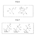
- FIG. 7 is a diagram illustrating a relationship between the line voltage vectors of the primary winding 11 and the line voltage vectors of the secondary windings 12b, 12c, and 12e.
- the phase of the line voltage vector V RS (see FIG. 6 ) from the S phase to the R phase is defined as the base phase.
- the line voltage vector V rs is as illustrated in FIG. 7 .
- the phase of the line voltage vector V rs from the s phase to the r phase of the secondary winding 12b is advanced 165 degrees with respect to the base phase.
- the connections ( FIG. 5 ) for the secondary windings 12c and 12e are performed similarly to the secondary winding 12b, and the phases of the line voltage vectors V rs from the s phase to the r phase of the secondary windings 12c and 12e are respectively advanced 155 degrees and 175 degrees with respect to the base phase.
- the position of each tap of the secondary windings 12c and 12e is different from that of the secondary winding 12b.
- the secondary windings 12c and 12e have the number of windings of a delta portion different from that of the secondary winding 12b.
- the secondary winding 12d is explained. As illustrated in FIG. 5 , the secondary winding 12d is also formed by extended delta connection. More specifically, the R-phase primary winding 11a and a secondary winding 12d1 are wound around the same iron core isolated by the insulation member, the S-phase primary winding 11b and a secondary winding 12d2 are wound around the same iron core isolated by the insulation member, and the T-phase primary winding 11c and a secondary winding 12d3 are wound around the same iron core isolated by the insulation member. All the secondary windings 12d1 to 12d3 have taps provided between their coil ends thereof.
- the negative coil ends of the secondary windings 12d1, 12d2, and 12d3 respectively correspond to the output ends of r-phase, s-phase, and t-phase.
- the positive coil end of the secondary winding 12d1 is connected to the tap of the secondary winding 12d3
- the positive coil end of the secondary winding 12d2 is connected to the tap of the secondary winding 12d1
- the positive coil end of the secondary winding 12d3 is connected to the tap of the secondary winding 12d2.
- FIG. 8 is a diagram illustrating a relationship between the line voltage vectors of the primary winding 11 and the line voltage vectors of the secondary windings 12d and 12f.
- the phase of the line voltage vector V RS (see FIG. 6 ) from the S phase to the R phase is defined as the base phase.
- the line voltage vectors V rs , V st , and V tr between the phases of the secondary windings 12d1, 12d2, and 12d3 are expressed with Equations (1) to (3) by using the phase voltage vectors V r , V s , and V t , similarly to the case of the secondary winding 12a.
- the phase of the line voltage vector V rs , of the line voltage vectors V rs , V st , and V tr is advanced 185 degrees with respect to the base phase as illustrated in FIG. 8 .
- connection ( FIG. 5 ) for the secondary winding 12f is performed similarly to the secondary winding 12b, and the phase of the line voltage vector V rs from the s phase to the r phase of the secondary winding 12f is advanced 205 degrees with respect to the base phase.
- the position of each tap of the secondary winding 12f is different from that of the secondary winding 12d.
- the secondary winding 12f has the number of windings of a delta portion different from that of the secondary winding 12d.
- FIGs. 9 and 10 are diagrams illustrating current vectors of the secondary windings 12 of the multi-winding transformer 10.
- a current vector I rs indicates a current between the r phase and the s phase and a current vector I tr indicates a current between the t phase and the r phase.
- the current vector I rs is a vector of a current of charging the capacitor C10 via the diodes D10, D11, D12 and D13 (see FIG. 2 ) connected to the r phase and the s phase.
- the current vector I tr is a vector of a current of charging the capacitor C10 via the diodes D10, D11, D14, and D15 connected to the t phase and the r phase.
- a current indicated by the current vector I rs flows when a line voltage between the r phase and the s phase among three line voltages becomes the maximum or minimum.
- a current indicated by the current vector I tr flows when a line voltage between the t phase and the r phase among the three line voltages becomes the maximum or minimum.
- the positive direction of a current vector indicated by a symbol is a direction in which a current flows from the secondary winding 12 to the rectification/smoothing unit 30 in the phase designated by the first subscript of the two subscripts of the symbol and flows from the rectification/smoothing unit 30 to the secondary winding 12 in the phase designated by the second subscript.
- an r-phase voltage is a positive voltage and an s-phase voltage is a negative voltage. Therefore, when the line voltage between the r phase and the s phase is the maximum, a current flows from each the secondary winding 12 to the rectification/smoothing unit 30 in the r phase and a current flows from the rectification/smoothing unit 30 to each the secondary winding 12 in the s phase. Therefore, the direction of the current vector I rs at this time is positive and, as illustrated in FIG. 9 , the current vectors I rs have the same directions as those of the line voltage vectors V rs in FIGs. 6 to 8 .
- a t-phase voltage is a negative voltage and the r-phase voltage is a positive voltage. Therefore, when the line voltage between the t phase and the r phase is the minium, a current flows from the rectification/smoothing unit 30 to each the secondary winding 12 in the t phase and a current flows from each the secondary winding 12 to the rectification/smoothing unit 30 in the r phase. Therefore, the direction of the current vector I tr at this time is negative and, as illustrated in FIG. 9 , the current vectors I tr have the directions opposite to those of the line voltage vectors V tr in FIGs. 6 to 8 .
- the r-phase voltage is a negative voltage and the s-phase voltage is a positive voltage. Therefore, when the line voltage between the r phase and the s phase is the minimum, a current flows from the rectification/smoothing unit 30 to each the secondary winding 12 in the r phase and a current flows from each the secondary winding 12 to the rectification/smoothing unit 30 in the s phase. Therefore, the direction of the current vector I rs at this time is negative and, as illustrated in FIG. 10 , the current vectors I rs have the directions opposite to those of the line voltage vectors V rs in FIGs. 6 to 8 .
- the t-phase voltage is a positive voltage and the r-phase voltage is a negative voltage. Therefore, when the line voltage between the t phase and the r phase is the maximum, a current flows from each the secondary winding 12 to the rectification/smoothing unit 30 in the t phase and a current flows from the rectification/smoothing unit 30 to each the secondary winding 12 in the s phase. Therefore, the direction of the current vector I tr of the current between the t phase and the r phase at this time is positive and, as illustrated in FIG. 10 , the current vectors I tr have the same directions as those of the line voltage vectors V tr in FIGs. 6 to 8 .
- FIG. 11 is a diagram explaining a current in each the secondary winding 12 in the r phase.
- a relationship of a line voltage Vrs between the r phase and the s phase, a line voltage Vtr between the t phase and the r phase, a phase voltage Vr of the r phase, and a phase current Ir of the r phase is illustrated in FIG. 11 .
- a steepled-wave current actually flows in the four cases. In the case of the s phase and the t phase, currents flow through the secondary windings 12 similarly to the case of the r phase.
- a direction of a current flowing out of the primary winding 11a is a positive direction.
- the direction of the current in the primary winding 11a for cancelling the magnetomotive force caused by the current flowing out of the secondary winding 12a1 is a direction of a current flowing into the primary winding 11a, namely, a negative direction opposite to that of the secondary winding 12a1.
- a current whose direction is an opposite direction to the current vector I rs and magnitude is obtained by multiplying the magnitude of the current vector I rs by a winding ratio of the primary winding 11a and the star connection portion of the secondary winding 12a1, flows through the primary winding 11a.
- a current whose direction is an opposite direction to the current vector I tr and magnitude is obtained by multiplying the magnitude of the current vector I tr by a winding ratio of the primary winding 11a and the secondary winding 12a1 also flows through the primary winding 11a.
- a current in the secondary winding 12b will be explained. Also, in the case of the secondary winding 12b, a current for cancelling a magnetomotive force caused by the current vector I rs and the current vector I tr of the secondary winding 12b1 flows through the primary winding 11a, in which the secondary winding 12b1 and the primary winding 11a are wound around the same iron core. From the wiring of the windings illustrated in FIG. 5 , it turns out that the direction of the current in the primary winding 11a for canceling the magnetomotive force caused by the current flowing out of the secondary winding 12b1 is a direction of a current flowing out of the primary winding 11a, namely, the positive direction same as that of the secondary winding 12b.
- a current whose direction is the same direction as the current vector I rs and magnitude is obtained by multiplying the magnitude of the current vector I rs by a winding ratio of the primary winding 11a and the secondary winding 12b1, also flows through the primary winding 11a.
- a current whose direction is the same direction as the current vector I tr and magnitude is obtained by multiplying the magnitude of the current vector I tr by a winding ratio of the primary winding 11a and the star connection portion of the secondary winding 12b1, flows through the primary winding 11a.
- a current for cancelling a magnetomotive force caused by the current vector I rs and the current vector I tr of each of secondary windings 12c1 and 12e1 flows through the primary winding 11a, in which each of the secondary windings 12c1 and 12e1 and the primary winding 11a are wound around the same iron core. Because the connection state of the secondary windings 12c1 and 12e1 is the same as that of the secondary winding 12b1 as illustrated in FIG. 5 , currents by the current vectors I rs and I tr of the secondary windings 12c1 and 12e1 flow through the primary winding 11a in accordance with the same converting action as that of the secondary winding 12b1.
- the direction of the current in the primary winding 11a for canceling the magnetomotive force caused by the current flowing out of the secondary winding 12d1 is a direction flowing out of the primary winding 11a similarly to the secondary windings 12b1, 12c1, and 12e1, namely, the positive direction similarly to the secondary winding 12d1.
- a current whose direction is the same direction as the current vector I rs and magnitude is obtained by multiplying the magnitude of the current vector I rs by a winding ratio of the primary winding 11a and the star connection portion of the secondary winding 12d1, also flows through the primary winding 11a.
- a current whose direction is the same direction as the current vector I tr and magnitude is obtained by multiplying the magnitude of the current vector I tr by a winding ratio of the primary winding 11a and the secondary winding 12d1, flows through the primary winding 11a.
- a current for cancelling a magnetomotive force caused by the current vector I rs and the current vector I tr of a secondary winding 12f1 flows through the primary winding 11a, in which the secondary winding 12f1 and the primary winding 11a are wound around the same iron core. Because the connection state of the secondary winding 12f1 is the same as that of the secondary winding 12d1 as illustrated in FIG. 5 , the current by the current vectors I rs and I tr of the secondary winding 12f1 flows through the primary winding 11a in accordance with the same converting action as the case of the secondary winding 12d1.
- the current whose direction is the above direction with respect to the current vectors I rs and I tr of each of the secondary windings 12 and magnitude is in accordance with the winding ratio of the primary winding 11a and the winding of the secondary windings 12 through which the r-phase current flows due to the current vectors I rs and I tr , flows through the primary winding 11a.
- FIG. 12 is a diagram illustrating the current vectors of the currents in the primary winding 11a caused by the currents in the secondary windings 12a to 12f when the r-phase voltage in the secondary windings 12a to 12f is positive.
- FIG. 13 is a diagram illustrating the current vectors of the currents in the primary winding 11a caused by the currents in the secondary windings 12a to 12f when the phase voltage Vr of the r-phase in the secondary windings 12a to 12f is negative.
- the current vectors of the currents in the primary winding 11a caused by the currents in the secondary windings 12a to 12f when a primary voltage V R is the positive voltage are as illustrated in FIG. 12 .
- the current vectors of the currents in the primary winding 11a caused by the currents in the secondary windings 12a to 12f when the primary voltage V R is the negative voltage are as illustrated in FIG. 13 .
- the currents with the phase difference of 10 degrees in the primary winding 11a caused by the current vectors I rs and I tr of the secondary windings 12a to 12f are symmetrically distributed with respect to the phase at which the R-phase voltage is the maximum.
- the current vector I rs of each the secondary winding 12 flows when the line voltage between the r phase and the s phase becomes the maximum or minimum among the three line voltages as described above, and its waveform is steepled.
- the current vector I tr of each the secondary winding 12 flows when the line voltage between the t phase and the r phase becomes the maximum or minimum among the three line voltages as described above, and its waveform is steepled.
- the series-connected multi-level power conversion device 1 of the first embodiment has a relationship that the voltage phase difference between the two secondary windings 12 respectively connected to the two single-phase power converters 21 in the same output phase is 30 degrees. Furthermore, the series-connected multi-level power conversion device 1 has a relationship that the voltage phase difference between the three secondary windings 12 respectively connected to the three single-phase power converters 21 corresponding to three output phases of the U phase, the V phase, and the W phase is 20 degrees.
- this configuration in the series-connected multi-level power conversion device 1 with the six single-phase power converters 21a to 21f connected to the six secondary windings 12a to 12f generates steepled-wave currents with the phase difference of 10 degrees in the primary winding 11 as illustrated in FIG. 12 or 13 . Therefore, an influence by the steepled-wave currents can be dispersed and thus current harmonics of the three-phase AC power source 2 are able to be reduced.
- the voltage phase difference between the secondary windings 12 connected to the single-phase power converters 21 corresponding to the three output phases of the U phase, the V phase, and the W phase, in which the single-phase power converters 21 are on the position which has the same stage number in each output phase is 20 degrees.
- the embodiment is not limited to this.
- FIG. 14 is a diagram illustrating another voltage phase relationship among the secondary windings 12 of the multi-winding transformer 10. As illustrated in FIG. 14 , it is only necessary that the voltage phase difference between the m secondary windings 12 (one set) obtained by selecting one secondary winding 12 from those connected to the single-phase power converters 21 serially connected to each other for each output phase is 60/m degrees.
- FIG. 15 is a diagram illustrating voltage phase differences between secondary windings of a multi-winding transformer of a series-connected multi-level power conversion device 1B according to the second embodiment.
- a voltage phase difference between the three secondary windings 12 respectively connected to the three single-phase power converters 21 in the same output phase is 20 degrees. More specifically, in the case of the U phase, the voltage phase difference is 20 degrees between the secondary windings 12 corresponding to the positions U1 and U2. Moreover, the voltage phase difference is 20 degrees between the secondary windings 12 corresponding to the positions U2 and U3. This relationship is similarly applied to the V and W phases.
- a voltage phase difference between the three secondary windings 12 respectively connected to the three single-phase power converters 21 corresponding to different output phases is 20 degrees. More specifically, the voltage phase difference is 20 degrees between the secondary windings 12 corresponding to the positions U1 and V1. Moreover, the voltage phase difference is 20 degrees between the secondary windings 12 corresponding to the positions V1 and W1. This relationship is similarly applied to the secondary windings 12 corresponding to the positions (U2, V2, W2) and the positions (U3, V3, W3).
- the embodiment is not limited to the relationship illustrated in FIG. 15 .
- the series-connected multi-level power conversion device 1B has the voltage phase difference of 20 degrees between the three secondary windings 12 respectively connected to the three single-phase power converters 21 in the same output phase. Furthermore, the series-connected multi-level power conversion device 1B has the voltage phase difference of 20 degrees between the three secondary windings 12 respectively connected to the three single-phase power converters 21 corresponding to the three output phases of the U phase, the V phase, and the W phase.
- the number of output phases and the number of the single-phase power converters 21 that constitute each output phase are not limited to the configuration.
- the voltage phases of the secondary windings 12 are advanced in order of the U phase, the V phase, and the W phase (U phase -> V phase -> W phase) as an example (see FIG. 4 ).
- the embodiments are not limited to this.
- the voltage phases of the secondary windings 12 may be advanced like (V phase -> W phase -> U phase) or (W phase -> U phase -> V phase).
- the voltage phases of the secondary windings 12 may be delayed like (V phase -> W phase -> U phase), (W phase -> U phase -> V phase), or (U phase -> V phase -> W phase).
- n and m are coprime.
Abstract
Description
- The embodiments discussed herein are directed to a series-connected multi-level power conversion device.
- As a conventional power conversion device, there is known a series-connected multi-level power conversion device that has a plurality of output phases each of which is constituted by serially-connected power conversion cells. The series-connected multi-level power conversion device includes a multi-winding transformer and a plurality of single-phase power converters. The multi-winding transformer transforms a multiphase alternating input voltage into a primary winding and outputs the transformed voltage to a plurality of secondary windings. The plurality of single-phase power converters are respectively connected to the secondary windings of the multi-winding transformer.
- In the series-connected multi-level power conversion device, the secondary windings of the multi-winding transformer output voltages whose phases are different from one another in order to reduce a harmonic current in the primary winding. More specifically, there has been proposed a method in which, when the series-connected multi-level power conversion device includes nine single-phase power converters, secondary windings connected to three single-phase power converters that constitutes one of U, V, and W phases have a voltage phase difference of 20 degrees and all the secondary windings have a voltage phase difference of 20/3 degrees. This method has been known as disclosed in, for example, Japanese Laid-open Patent Publication No.
2008-295149 - An aspect of embodiments has an object of the embodiments to provide a new technology substituting for a conventional technology to reduce a harmonic current in a primary winding.
- A series-connected multi-level power conversion device according to an aspect of embodiments includes a multi-winding transformer and a power conversion unit. The multi-winding transformer distributes AC power input into a primary winding to m×n (n and m are coprime) secondary windings. The power conversion unit includes m×n single-phase power converters that are respectively connected to the m×n secondary windings, in which each of m output phases is constituted by serially connected outputs of the n single-phase power converters. The multi-winding transformer has a relationship that the n secondary windings respectively connected to the n single-phase power converters in one output phase have a voltage phase difference of 60/n degrees. Furthermore, the multi-winding transformer has a relationship that the m secondary windings respectively connected to the m single-phase power converters corresponding to the m output phases have a voltage phase difference of 60/m degrees.
- According to an aspect of embodiments, it is possible to reduce a harmonic current in a primary winding.
- A more complete appreciation of the invention and many of the attendant advantages thereof will be readily obtained as the same becomes better understood by reference to the following detailed description when considered in connection with the accompanying drawings, wherein:
-
FIG. 1 is a diagram illustrating a series-connected multi-level power conversion device according to a first embodiment; -
FIG. 2 is a diagram illustrating a circuit block of a single-phase power converter illustrated inFIG. 1 ; -
FIG. 3 is a diagram illustrating voltage phase differences between secondary windings of a multi-winding transformer; -
FIG. 4 is a diagram illustrating a voltage phase relationship among the secondary windings of the multi-winding transformer; -
FIG. 5 is a diagram illustrating wiring of the multi-winding transformer; -
FIGs. 6 to 8 are diagrams illustrating relationships between line voltage vectors of a primary winding and line voltage vectors of the secondary winding of the multi-winding transformer; -
FIG. 9 is a diagram illustrating current vectors of each secondary winding of the multi-winding transformer; -
FIG. 10 is a diagram illustrating current vectors of each secondary winding of the multi-winding transformer; -
FIG. 11 is a diagram explaining a current in each secondary winding in an r phase; -
FIG. 12 is a diagram illustrating current vectors in the primary winding caused by currents in the secondary windings when a primary voltage is positive; -
FIG. 13 is a diagram illustrating current vectors in the primary winding caused by currents in the secondary windings when the primary voltage is negative; -
FIG. 14 is a diagram illustrating another voltage phase relationship among the secondary windings of the multi-winding transformer; and -
FIG. 15 is a diagram illustrating voltage phase differences between secondary windings of a multi-winding transformer of a series-connected multi-level power conversion device according to a second embodiment. - Hereinafter, a series-connected multi-level power conversion device according to embodiments of the present disclosure will be explained in detail with reference to the accompanying drawings. In addition, the embodiments disclosed below are not intended to limit the present invention.
- First, the configuration of a series-connected multi-level power conversion device according to the first embodiment will be explained.
FIG. 1 is a diagram illustrating a series-connected multi-levelpower conversion device 1 according to the first embodiment. - As illustrated in
FIG. 1 , the series-connected multi-levelpower conversion device 1 includes amulti-winding transformer 10 and apower conversion unit 20. The series-connected multi-levelpower conversion device 1 converts an R-phase, S-phase, and T-phase AC power from a three-phaseAC power source 2 into an AC power and supplies the converted power to an alternating-current load 3. Herein, as an example, it is explained that the series-connected multi-level power conversion,device 1 has three output phases (m=3) each of which is constituted by two-stage (n=2) single-phase power converters and the alternating-current load 3 is a motor. - The
multi-winding transformer 10 includes a primary winding 11 and sixsecondary windings 12a to 12f (hereinafter, they may be referred to as secondary windings 12). Themulti-winding transformer 10 transforms an AC power input into theprimary winding 11 and outputs the transformed power to the sixsecondary windings 12a to 12f. Themulti-winding transformer 10 is a phase-shifting transformer that generates voltage phase differences between theprimary winding 11 and thesecondary windings 12. - The
power conversion unit 20 includes six single-phase power converters 21a to 21f (hereinafter, they may be referred to as single-phase power converters 21) that are respectively connected to the sixsecondary windings 12a to 12f. Each of the single-phase power converters 21 converts three-phase AC power from the correspondingsecondary winding 12 into single-phase AC power and outputs the converted AC power through its own output terminals Ta and Tb. - In the
power conversion unit 20, serially-connected outputs of the two single-phase power converters 21 constitute one output phase. In other words, a U-phase power conversion unit is constituted by the single-phase power converters phase power converters phase power converters - More specifically, the output terminal Tb of the single-
phase power converter 21a is connected to a neutral point N, and the output terminal Ta of the single-phase power converter 21a is connected to the output terminal Tb of the single-phase power converter 21d. This connection leads to the configuration of the U-phase power conversion unit whose output terminal is the output terminal Ta of the single-phase power converter 21d. - Similarly, the output terminals Tb of the single-
phase power converters phase power converters phase power converters phase power converters - Now, the configuration of the single-
phase power converter 21 will be explained.FIG. 2 is a diagram illustrating a circuit block of the single-phase power converter 21. As illustrated inFIG. 2 , the single-phase power converter 21 includes a rectification/smoothing unit 30, aninverter unit 31, and acontrol unit 32. - The rectification/
smoothing unit 30 includes diodes D10 to D15 and a capacitor C10. The rectification/smoothing unit 30 converts the three-phase (r phase, s phase, and t phase) AC power from the correspondingsecondary winding 12 into a DC power. In this case, the diodes D10 and D11 perform full-wave rectification on the r-phase power, the diodes D12 and D13 perform full-wave rectification on the s-phase power, and the diodes D14 and D15 perform full-wave rectification on the t-phase power. Then, the voltage rectified by the diodes D10 to D15 is smoothed by the capacitor C10. - The
inverter unit 31 includes transistors Q20 to Q23 and diodes D20 to D23. The transistors Q20 and Q21 are serially connected between the outputs of the rectification/smoothing unit 30. Similarly, the transistors Q22 and Q23 are serially connected between the outputs of the rectification/smoothing unit 30. Herein, the diodes D20 to D23 are freewheeling diodes. - The
control unit 32 controls ON/OFF states of the transistors Q20 to Q23 of theinverter unit 31 to make theinverter unit 31 convert the DC power of the rectification/smoothing unit 30 into single-phase AC power. The transistors Q20 to Q23 uses power semiconductor devices such as IGBT and MOSFET. Theinverter unit 31 is not limited to the configuration of the two-level inverter illustrated inFIG. 2 . For example, theinverter unit 31 can employ the configuration of a multi-level inverter such as a three-level inverter. Moreover, theinverter unit 31 can employ the other various configurations. - Next, the configuration of the
multi-winding transformer 10 will be explained.FIG. 3 is a diagram illustrating voltage phase differences between thesecondary windings 12a to 12f.FIG. 4 is a diagram illustrating a voltage phase relationship among thesecondary windings 12a to 12f. As described above, the single-phase power converters 21a to 21f are respectively located at U1, V1, W1, U2, V2, and W2, and are respectively connected to thesecondary windings 12a to 12f (seeFIG. 1 ). Herein, in the symbols U1 to W2, characters U, V, and W indicate output phases and numbers "1" and "2" indicate the order of stages that are serially connected in one output phase. Therefore, the secondary winding 12a corresponds to the position U1, the secondary winding 12b corresponds to the position V1, the secondary winding 12c corresponds to the position W1, the secondary winding 12d corresponds to the position U2, the secondary winding 12e corresponds to the position V2, and the secondary winding 12f corresponds to the position W2. - As illustrated in
FIG. 3 , in themulti-winding transformer 10 according to the first embodiment, a voltage phase difference between the twosecondary windings 12 respectively connected to the two single-phase power converters 21 in the same output phase is 30 degrees. More specifically, in the case of the U phase, a voltage phase difference between the secondary winding 12a corresponding to the position U1 and the secondary winding 12d corresponding to the position U2 is 30 degrees. - Similarly, in the case of the V phase, a voltage phase difference between the secondary winding 12b corresponding to the position V1 and the secondary winding 12e corresponding to the position V2 is 30 degrees. Moreover, in the case of the W phase, a voltage phase difference between the secondary winding 12c corresponding to the position W1 and the secondary winding 12f corresponding to the position W2 is 30 degrees.
- On the other hand, in the
multi-winding transformer 10, a voltage phase difference between the twosecondary windings 12 respectively connected to the two single-phase power converters 21 corresponding to the different output phases is 20 degrees. More specifically, a voltage phase difference between the secondary winding 12a corresponding to the position U1 and the secondary winding 12b corresponding to the position V1 is 20 degrees. Moreover, a voltage phase difference between the secondary winding 12b corresponding to the position V1 and the secondary winding 12c corresponding to the position W1 is 20 degrees. - Now, a specific example of the voltage phase differences between the
secondary windings 12a to 12f will be explained with reference toFIG. 4 . As illustrated inFIG. 4 , the voltage phases of thesecondary windings 12 are (135 degrees, 155 degrees, 165 degrees, 175 degrees, 185 degrees, 205 degrees) in order of (U1, V1, U2, W1, V2, W2). These voltage phases of thesecondary windings 12 are defined as phase differences between the voltages of thesecondary winnings 12 and the voltage of the primary winding 11. - Therefore, the voltage phases of the
secondary windings 12 are (U1, U2) = (135 degrees, 165 degrees) in the U phase, (V1, V2) = (155 degrees, 185 degrees) in the V phase, and (W1, W2) = (175 degrees, 205 degrees) in the W phase. The voltage phase difference between the voltages of thesecondary windings 12 in the same output phase is 30 degrees. Moreover, two groups of the voltage phases of thesecondary windings 12 corresponding to the different output phases are (U1, V1, W1) = (135 degrees, 155 degrees, 175 degrees) and (U2, V2, W2) = (165 degrees, 185 degrees, 205 degrees), and the two voltage phase differences in one group are 20 degrees. - A configuration example of the
multi-winding transformer 10 having the voltage phase relationship between thesecondary windings 12 illustrated inFIG. 4 is explained with reference toFIG. 5. FIG. 5 is a diagram illustrating wiring of themulti-winding transformer 10. - As illustrated in
FIG. 5 , the secondary winding 12a is formed by extended delta connection. More specifically, an R-phase primary winding 11a and a secondary winding 12a1 are wound around the same iron core isolated by an insulation member, an S-phase primary winding 11b and a secondary winding 12a2 are wound around the same iron core isolated by the insulation member, and a T-phase primary winding 11c and a secondary winding 12a3 are wound around the same iron core isolated by the insulation member. All the secondary windings 12a1 to 12a3 have taps provided between their coil ends thereof. - In
FIG. 5 , each winding includes a coil end that has a black dot and a coil end that does not have the black dot. When considering a pair of the primary winding and one of the plurality of secondary windings, a black dot is put on one side of coil ends of each winding in such a manner that magnetic fluxes made by both the windings have directions in which the fluxes are reinforced each other when currents flow into from the coil ends of the two windings that have black dots. Herein, the coil end that has the black dot is referred to as a positive coil end and the coil end opposite to the positive coil end is referred to as a negative coil end. InFIG. 5 , the positive coil ends of the secondary windings 12a1, 12a2, and 12a3 respectively correspond to the output ends of r-phase, s-phase, and t-phase. Moreover, the negative coil end of the secondary winding 12a1 is connected to the tap of the secondary winding 12a3, the negative coil end of the secondary winding 12a3 is connected to the tap of the secondary winding 12a2, and the negative coil end of the secondary winding 12a2 is connected to the tap of the secondary winding 12a1. - Herein, a relationship between the line voltage vectors of the primary winding 11 and the line voltage vectors of the secondary winding 12a when the connection illustrated in
FIG. 5 is made will be explained with reference toFIG. 6. FIG. 6 is a diagram illustrating a relationship between the line voltage vectors of the primary winding 11 and the line voltage vectors of the secondary winding 12a. The output phases of the three-phaseAC power source 2 are delayed in order of an R phase, an S phase, and a T phase to have a voltage phase difference of 120 degrees. - When the secondary windings 12a1, 12a2, and 12a3 are connected as described above, line voltage vectors Vrs, Vst, and Vtr between the phases of the secondary windings 12a1, 12a2, and 12a3 are expressed with the following Equations (1) to (3) by using phase voltage vectors Vr, Vs, and Vt.


- For example, the line voltage vectors Vrs and Vtr are as illustrated in
FIG. 6 . When the phase of a line voltage vector VRS from the S phase to the R phase of the primary winding 11 is defined as a base phase, the phase of the line voltage vector Vrs from the s phase to the r phase of the secondary winding 12a is advanced 15 degrees with respect to the base phase. - In the secondary winding 12a, the phase of the line voltage vector Vtr from the r phase to the t phase is advanced 120 degrees with respect to the phase of the line voltage vector Vrs and 135 degrees with respect to the base phase. Moreover, the phase of the line voltage vector Vst from the t phase to the s phase is advanced 240 degrees with respect to the phase of the line voltage vector Vrs and 255 degrees with respect to the base phase. Therefore, the secondary winding 12a is a secondary winding with a voltage phase that is advanced 15 degrees with respect to the base phase and is also a secondary winding with a voltage phase that is advanced 135 degrees with respect to the base phase. Furthermore, the secondary winding 12a is a secondary winding with a voltage phase that is advanced 255 degrees with respect to the base phase.
- Returning to
FIG. 5 , the secondary winding 12b is explained. As illustrated inFIG. 5 , the secondary winding 12b is formed by extended delta connection. More specifically, the R-phase primary winding 11a and a secondary winding 12b1 are wound around the same iron core isolated by the insulation member, the S-phase primary winding 11b and a secondary winding 12b2 are wound around the same iron core isolated by the insulation member, and the T-phase primary winding 11c and a secondary winding 12b3 are wound around the same iron core isolated by the insulation member. All the secondary windings 12b1 to 12b3 have taps provided between their coil ends thereof. - The negative coil ends of the secondary windings 12b1, 12b2, and 12b3 respectively correspond to the output ends of r-phase, s-phase, and t-phase. Moreover, the positive coil end of the secondary winding 12b1 is connected to the tap of the secondary winding 12b2, the positive coil end of the secondary winding 12b2 is connected to the tap of the secondary winding 12b3, and the positive coil end of the secondary winding 12b3 is connected to the tap of the secondary winding 12b1.
- Now, a relationship between the line voltage vectors of the primary winding 11 and the line voltage vectors of the secondary winding 12b when the connection illustrated in
FIG. 5 is made will be explained with reference toFIG. 7. FIG. 7 is a diagram illustrating a relationship between the line voltage vectors of the primary winding 11 and the line voltage vectors of thesecondary windings FIG. 6 ) from the S phase to the R phase is defined as the base phase. - When the secondary windings 12b1, 12b2, and 12b3 are connected as described above, line voltage vectors Vrs, Vst, and Vtr between the phases of the secondary windings 12b1, 12b2, and 12b3 are expressed with Equations (1) to (3) by using the phase voltage vectors Vr, Vs, and Vt, similarly to the case of the secondary winding 12a.
- For example, the line voltage vector Vrs is as illustrated in
FIG. 7 . In other words, the phase of the line voltage vector Vrs from the s phase to the r phase of the secondary winding 12b is advanced 165 degrees with respect to the base phase. - Similarly, the connections (
FIG. 5 ) for thesecondary windings secondary windings secondary windings secondary windings - Returning to
FIG. 5 , the secondary winding 12d is explained. As illustrated inFIG. 5 , the secondary winding 12d is also formed by extended delta connection. More specifically, the R-phase primary winding 11a and a secondary winding 12d1 are wound around the same iron core isolated by the insulation member, the S-phase primary winding 11b and a secondary winding 12d2 are wound around the same iron core isolated by the insulation member, and the T-phase primary winding 11c and a secondary winding 12d3 are wound around the same iron core isolated by the insulation member. All the secondary windings 12d1 to 12d3 have taps provided between their coil ends thereof. - The negative coil ends of the secondary windings 12d1, 12d2, and 12d3 respectively correspond to the output ends of r-phase, s-phase, and t-phase. Moreover, the positive coil end of the secondary winding 12d1 is connected to the tap of the secondary winding 12d3, the positive coil end of the secondary winding 12d2 is connected to the tap of the secondary winding 12d1, and the positive coil end of the secondary winding 12d3 is connected to the tap of the secondary winding 12d2.
- Now, a relationship between the line voltage vectors of the primary winding 11 and the line voltage vectors of the
secondary windings FIG. 5 is performed will be explained with reference toFIG. 8. FIG. 8 is a diagram illustrating a relationship between the line voltage vectors of the primary winding 11 and the line voltage vectors of thesecondary windings FIG. 6 ) from the S phase to the R phase is defined as the base phase. - When the secondary windings 12d1, 12d2, and 12d3 are connected as described above, the line voltage vectors Vrs, Vst, and Vtr between the phases of the secondary windings 12d1, 12d2, and 12d3 are expressed with Equations (1) to (3) by using the phase voltage vectors Vr, Vs, and Vt, similarly to the case of the secondary winding 12a. For example, the phase of the line voltage vector Vrs, of the line voltage vectors Vrs, Vst, and Vtr is advanced 185 degrees with respect to the base phase as illustrated in
FIG. 8 . - Similarly, as illustrated in
FIG. 8 , the connection (FIG. 5 ) for the secondary winding 12f is performed similarly to the secondary winding 12b, and the phase of the line voltage vector Vrs from the s phase to the r phase of the secondary winding 12f is advanced 205 degrees with respect to the base phase. In this case, the position of each tap of the secondary winding 12f is different from that of the secondary winding 12d. In other words, the secondary winding 12f has the number of windings of a delta portion different from that of the secondary winding 12d. - Next, current vectors of the
secondary windings 12 of themulti-winding transformer 10 will be explained with reference toFIGs. 9 and10 .FIGs. 9 and10 are diagrams illustrating current vectors of thesecondary windings 12 of themulti-winding transformer 10. - In
FIGs. 9 and10 , a current vector Irs indicates a current between the r phase and the s phase and a current vector Itr indicates a current between the t phase and the r phase. The current vector Irs is a vector of a current of charging the capacitor C10 via the diodes D10, D11, D12 and D13 (seeFIG. 2 ) connected to the r phase and the s phase. The current vector Itr is a vector of a current of charging the capacitor C10 via the diodes D10, D11, D14, and D15 connected to the t phase and the r phase. - A current indicated by the current vector Irs flows when a line voltage between the r phase and the s phase among three line voltages becomes the maximum or minimum. A current indicated by the current vector Itr flows when a line voltage between the t phase and the r phase among the three line voltages becomes the maximum or minimum. Hereinafter, it is assumed that the positive direction of a current vector indicated by a symbol is a direction in which a current flows from the secondary winding 12 to the rectification/smoothing
unit 30 in the phase designated by the first subscript of the two subscripts of the symbol and flows from the rectification/smoothingunit 30 to the secondary winding 12 in the phase designated by the second subscript. - When the line voltage between the r phase and the s phase becomes the maximum, an r-phase voltage is a positive voltage and an s-phase voltage is a negative voltage. Therefore, when the line voltage between the r phase and the s phase is the maximum, a current flows from each the secondary winding 12 to the rectification/smoothing
unit 30 in the r phase and a current flows from the rectification/smoothingunit 30 to each the secondary winding 12 in the s phase. Therefore, the direction of the current vector Irs at this time is positive and, as illustrated inFIG. 9 , the current vectors Irs have the same directions as those of the line voltage vectors Vrs inFIGs. 6 to 8 . - When the line voltage between the t phase and the r phase becomes the minimum, a t-phase voltage is a negative voltage and the r-phase voltage is a positive voltage. Therefore, when the line voltage between the t phase and the r phase is the minium, a current flows from the rectification/smoothing
unit 30 to each the secondary winding 12 in the t phase and a current flows from each the secondary winding 12 to the rectification/smoothingunit 30 in the r phase. Therefore, the direction of the current vector Itr at this time is negative and, as illustrated inFIG. 9 , the current vectors Itr have the directions opposite to those of the line voltage vectors Vtr inFIGs. 6 to 8 . - When the line voltage between the r phase and the s phase becomes the minimum, the r-phase voltage is a negative voltage and the s-phase voltage is a positive voltage. Therefore, when the line voltage between the r phase and the s phase is the minimum, a current flows from the rectification/smoothing
unit 30 to each the secondary winding 12 in the r phase and a current flows from each the secondary winding 12 to the rectification/smoothingunit 30 in the s phase. Therefore, the direction of the current vector Irs at this time is negative and, as illustrated inFIG. 10 , the current vectors Irs have the directions opposite to those of the line voltage vectors Vrs inFIGs. 6 to 8 . - When the line voltage between the t phase and the r phase becomes the maximum, the t-phase voltage is a positive voltage and the r-phase voltage is a negative voltage. Therefore, when the line voltage between the t phase and the r phase is the maximum, a current flows from each the secondary winding 12 to the rectification/smoothing
unit 30 in the t phase and a current flows from the rectification/smoothingunit 30 to each the secondary winding 12 in the s phase. Therefore, the direction of the current vector Itr of the current between the t phase and the r phase at this time is positive and, as illustrated inFIG. 10 , the current vectors Itr have the same directions as those of the line voltage vectors Vtr inFIGs. 6 to 8 . - As described above, the current in each the secondary winding 12 in the r phase can flow in four cases where the line voltage between the r phase and the s phase is the maximum and minimum and where the line voltage between the t phase and the r phase is the minimum and maximum.
FIG. 11 is a diagram explaining a current in each the secondary winding 12 in the r phase. A relationship of a line voltage Vrs between the r phase and the s phase, a line voltage Vtr between the t phase and the r phase, a phase voltage Vr of the r phase, and a phase current Ir of the r phase is illustrated inFIG. 11 . As illustrated inFIG. 11 , a steepled-wave current actually flows in the four cases. In the case of the s phase and the t phase, currents flow through thesecondary windings 12 similarly to the case of the r phase. - Next, currents in the R-phase primary winding 11a caused by the currents in the
secondary windings 12a to 12f will be explained. First, the current in the secondary winding 12a is explained as an example. When a current flows through the secondary winding 12a1, a current for canceling a magnetomotive force caused by the current in the secondary winding 12a1 flows through the R-phase primary winding 11a wound around the same iron core as the secondary winding 12a1 is wound around. In other words, a current for canceling a magnetomotive force caused by the current vector Irs and the current vector Itr described above flows through the primary winding 11a. - In the case of the current in the primary winding 11a, it is assumed that a direction of a current flowing out of the primary winding 11a is a positive direction. In the wiring of the windings illustrated in
FIG. 5 , from the definition of a positive coil end described above, it turns out that the direction of the current in the primary winding 11a for cancelling the magnetomotive force caused by the current flowing out of the secondary winding 12a1 is a direction of a current flowing into the primary winding 11a, namely, a negative direction opposite to that of the secondary winding 12a1. - Because the current vector Irs flows through a star connection portion of the secondary winding 12a1, a current, whose direction is an opposite direction to the current vector Irs and magnitude is obtained by multiplying the magnitude of the current vector Irs by a winding ratio of the primary winding 11a and the star connection portion of the secondary winding 12a1, flows through the primary winding 11a. Moreover, because the current vector Itr flows through the star and delta connection portions of the secondary winding 12a1, a current, whose direction is an opposite direction to the current vector Itr and magnitude is obtained by multiplying the magnitude of the current vector Itr by a winding ratio of the primary winding 11a and the secondary winding 12a1 also flows through the primary winding 11a.
- Next, a current in the secondary winding 12b will be explained. Also, in the case of the secondary winding 12b, a current for cancelling a magnetomotive force caused by the current vector Irs and the current vector Itr of the secondary winding 12b1 flows through the primary winding 11a, in which the secondary winding 12b1 and the primary winding 11a are wound around the same iron core. From the wiring of the windings illustrated in
FIG. 5 , it turns out that the direction of the current in the primary winding 11a for canceling the magnetomotive force caused by the current flowing out of the secondary winding 12b1 is a direction of a current flowing out of the primary winding 11a, namely, the positive direction same as that of the secondary winding 12b. - Because the current vector Irs flows through the star and delta connection portions in the secondary winding 12b1, a current, whose direction is the same direction as the current vector Irs and magnitude is obtained by multiplying the magnitude of the current vector Irs by a winding ratio of the primary winding 11a and the secondary winding 12b1, also flows through the primary winding 11a. Moreover, because the current vector Itr flows through the star connection portion of the secondary winding 12b1, a current, whose direction is the same direction as the current vector Itr and magnitude is obtained by multiplying the magnitude of the current vector Itr by a winding ratio of the primary winding 11a and the star connection portion of the secondary winding 12b1, flows through the primary winding 11a.
- Also, in the case of the
secondary windings FIG. 5 , currents by the current vectors Irs and Itr of the secondary windings 12c1 and 12e1 flow through the primary winding 11a in accordance with the same converting action as that of the secondary winding 12b1. - Next, a current in the secondary winding 12d will be explained. Also, in the case of the secondary winding 12d, a current for cancelling a magnetomotive force caused by the current vector Irs and the current vector Itr of the secondary winding 12d1 flows through the primary winding 11a, in which the secondary winding 12d1 and the primary winding 11a are wound around the same iron core. From the wiring of the windings illustrated in
FIG. 5 , it turns out that the direction of the current in the primary winding 11a for canceling the magnetomotive force caused by the current flowing out of the secondary winding 12d1 is a direction flowing out of the primary winding 11a similarly to the secondary windings 12b1, 12c1, and 12e1, namely, the positive direction similarly to the secondary winding 12d1. - Because the current vector Irs flows through the star connection portion in the secondary winding 12d1, a current, whose direction is the same direction as the current vector Irs and magnitude is obtained by multiplying the magnitude of the current vector Irs by a winding ratio of the primary winding 11a and the star connection portion of the secondary winding 12d1, also flows through the primary winding 11a. Moreover, because the current vector Itr flows through the star and delta connection portions of the secondary winding 12d1, a current, whose direction is the same direction as the current vector Itr and magnitude is obtained by multiplying the magnitude of the current vector Itr by a winding ratio of the primary winding 11a and the secondary winding 12d1, flows through the primary winding 11a.
- Also, in the case of the secondary winding 12f, a current for cancelling a magnetomotive force caused by the current vector Irs and the current vector Itr of a secondary winding 12f1 flows through the primary winding 11a, in which the secondary winding 12f1 and the primary winding 11a are wound around the same iron core. Because the connection state of the secondary winding 12f1 is the same as that of the secondary winding 12d1 as illustrated in
FIG. 5 , the current by the current vectors Irs and Itr of the secondary winding 12f1 flows through the primary winding 11a in accordance with the same converting action as the case of the secondary winding 12d1. - As described above, the current, whose direction is the above direction with respect to the current vectors Irs and Itr of each of the
secondary windings 12 and magnitude is in accordance with the winding ratio of the primary winding 11a and the winding of thesecondary windings 12 through which the r-phase current flows due to the current vectors Irs and Itr, flows through the primary winding 11a. - Therefore, the current vectors of the currents in the primary winding 11a caused by the currents in the
secondary windings 12a to 12f are as illustrated inFIG. 12. FIG. 12 is a diagram illustrating the current vectors of the currents in the primary winding 11a caused by the currents in thesecondary windings 12a to 12f when the r-phase voltage in thesecondary windings 12a to 12f is positive. - On the other hand, as illustrated in
FIG. 13 , when the phase voltage Vr of the r phase is negative, the current vectors of the currents in the primary winding 11a caused by the currents in thesecondary windings 12a to 12f have a phase difference of 180 degrees with respect to the current vectors illustrated inFIG. 12. FIG. 13 is a diagram illustrating the current vectors of the currents in the primary winding 11a caused by the currents in thesecondary windings 12a to 12f when the phase voltage Vr of the r-phase in thesecondary windings 12a to 12f is negative. - Therefore, the current vectors of the currents in the primary winding 11a caused by the currents in the
secondary windings 12a to 12f when a primary voltage VR is the positive voltage are as illustrated inFIG. 12 . On the other hand, the current vectors of the currents in the primary winding 11a caused by the currents in thesecondary windings 12a to 12f when the primary voltage VR is the negative voltage are as illustrated inFIG. 13 . - As illustrated in
FIGs. 12 and 13 , the currents with the phase difference of 10 degrees in the primary winding 11a caused by the current vectors Irs and Itr of thesecondary windings 12a to 12f are symmetrically distributed with respect to the phase at which the R-phase voltage is the maximum. The current vector Irs of each the secondary winding 12 flows when the line voltage between the r phase and the s phase becomes the maximum or minimum among the three line voltages as described above, and its waveform is steepled. Moreover, the current vector Itr of each the secondary winding 12 flows when the line voltage between the t phase and the r phase becomes the maximum or minimum among the three line voltages as described above, and its waveform is steepled. - However, because the current vectors of the currents in the primary winding 11a caused by the currents in the
secondary windings 12 are distributed as described above, an influence by the steepled-wave currents is dispersed and thus current harmonics are reduced. Because the same currents also flow through the S-phase and T-phaseprimary windings AC power source 2 are able to be reduced. - As described above, the series-connected multi-level
power conversion device 1 of the first embodiment has a relationship that the voltage phase difference between the twosecondary windings 12 respectively connected to the two single-phase power converters 21 in the same output phase is 30 degrees. Furthermore, the series-connected multi-levelpower conversion device 1 has a relationship that the voltage phase difference between the threesecondary windings 12 respectively connected to the three single-phase power converters 21 corresponding to three output phases of the U phase, the V phase, and the W phase is 20 degrees. - In the first embodiment, this configuration in the series-connected multi-level
power conversion device 1 with the six single-phase power converters 21a to 21f connected to the sixsecondary windings 12a to 12f generates steepled-wave currents with the phase difference of 10 degrees in the primary winding 11 as illustrated inFIG. 12 or 13 . Therefore, an influence by the steepled-wave currents can be dispersed and thus current harmonics of the three-phaseAC power source 2 are able to be reduced. - In the example described above, it has been explained that the voltage phase difference between the
secondary windings 12 connected to the single-phase power converters 21 corresponding to the three output phases of the U phase, the V phase, and the W phase, in which the single-phase power converters 21 are on the position which has the same stage number in each output phase, is 20 degrees. However, the embodiment is not limited to this. For example, there may be a series-connected multi-levelpower conversion device 1A in which thesecondary windings 12 are connected to the single-phase power converters 21 under a positional relationship as illustrated inFIG. 14. FIG. 14 is a diagram illustrating another voltage phase relationship among thesecondary windings 12 of themulti-winding transformer 10. As illustrated inFIG. 14 , it is only necessary that the voltage phase difference between the m secondary windings 12 (one set) obtained by selecting one secondary winding 12 from those connected to the single-phase power converters 21 serially connected to each other for each output phase is 60/m degrees. -
FIG. 15 is a diagram illustrating voltage phase differences between secondary windings of a multi-winding transformer of a series-connected multi-levelpower conversion device 1B according to the second embodiment. The series-connected multi-levelpower conversion device 1B according to the second embodiment has a configuration different from those of the series-connected multi-levelpower conversion devices phase power converters 21. - As illustrated in
FIG. 15 , in the series-connected multi-levelpower conversion device 1B according to the second embodiment, a voltage phase difference between the threesecondary windings 12 respectively connected to the three single-phase power converters 21 in the same output phase is 20 degrees. More specifically, in the case of the U phase, the voltage phase difference is 20 degrees between thesecondary windings 12 corresponding to the positions U1 and U2. Moreover, the voltage phase difference is 20 degrees between thesecondary windings 12 corresponding to the positions U2 and U3. This relationship is similarly applied to the V and W phases. - On the other hand, in the multi-winding transformer of the series-connected multi-level
power conversion device 1B, a voltage phase difference between the threesecondary windings 12 respectively connected to the three single-phase power converters 21 corresponding to different output phases is 20 degrees. More specifically, the voltage phase difference is 20 degrees between thesecondary windings 12 corresponding to the positions U1 and V1. Moreover, the voltage phase difference is 20 degrees between thesecondary windings 12 corresponding to the positions V1 and W1. This relationship is similarly applied to thesecondary windings 12 corresponding to the positions (U2, V2, W2) and the positions (U3, V3, W3). - Similarly to the first embodiment, it is only necessary that the voltage phase difference between the m secondary windings 12 (one set) obtained by selecting one secondary winding 21 from those connected to the single-
phase power converters 21 serially connected to each other for each output phase is 60/m degrees. Therefore, the embodiment is not limited to the relationship illustrated inFIG. 15 . - As described above, the series-connected multi-level
power conversion device 1B according to the second embodiment has the voltage phase difference of 20 degrees between the threesecondary windings 12 respectively connected to the three single-phase power converters 21 in the same output phase. Furthermore, the series-connected multi-levelpower conversion device 1B has the voltage phase difference of 20 degrees between the threesecondary windings 12 respectively connected to the three single-phase power converters 21 corresponding to the three output phases of the U phase, the V phase, and the W phase. - Therefore, in the series-connected multi-level
power conversion device 1B of the second embodiment, steepled-wave currents with the phase difference of 20/3 degrees are generated in the phases of the primary winding 11 due to the nine single-phase power converters 21 connected to the ninesecondary windings 12. As a result, an influence by current pulses can be dispersed and thus current harmonics of the three-phaseAC power source 2 are able to be reduced. - In the embodiments, the series-connected multi-level
power conversion devices phase power converters 21, has been explained. The number of output phases and the number of the single-phase power converters 21 that constitute each output phase are not limited to the configuration. - It has been explained in the embodiments that the voltage phases of the
secondary windings 12 are advanced in order of the U phase, the V phase, and the W phase (U phase -> V phase -> W phase) as an example (seeFIG. 4 ). However, the embodiments are not limited to this. For example, the voltage phases of thesecondary windings 12 may be advanced like (V phase -> W phase -> U phase) or (W phase -> U phase -> V phase). Alternatively, the voltage phases of thesecondary windings 12 may be delayed like (V phase -> W phase -> U phase), (W phase -> U phase -> V phase), or (U phase -> V phase -> W phase). - In other words, it is only necessary that the
multi-winding transformer 10 satisfies the following conditions. Herein, n and m are coprime. - (1) A voltage phase difference between the n
secondary windings 12 respectively connected to the n single-phase power converters 21 in the same output phase is 60/n degrees. - (2) A voltage phase difference between the
secondary windings 12 connected to the single-phase power converters 21 corresponding to m output phases is 60/m degrees.
Claims (3)
- A series-connected multi-level power conversion device (1, 1A, 1B) comprising:a multi-winding transformer (10) that distributes AC power input into a primary winding (11) to m×n (n and m are coprime) secondary windings (12a to 12f); anda power conversion unit (20) that includes m×n single-phase power converters (21a to 21f) that are respectively connected to the m×n secondary windings (12a to 12f), each of m output phases being constituted by serially connected outputs of the n single-phase power converters (21a to 21f), whereinthe multi-winding transformer (10) has a relationship that the n secondary windings (12a to 12f) respectively connected to the n single-phase power converters (21a to 21f) in a same output phase have a voltage phase difference of 60/n degrees and a relationship that the m secondary windings (12a to 12f) respectively connected to the m single-phase power converters (21a to 21f) corresponding to the m output phases have a voltage phase difference of 60/m degrees.
- The series-connected multi-level power conversion device (1, 1A, 1B) according to claim 1, wherein the multi-winding transformer (10) has a relationship that the secondary windings (12a to 12f) connected to the m single-phase power converters (21a to 21f) corresponding to the m output phases, in which each of the m single-phase power converters (21a to 21f) is on a same ordinal position in the corresponding output phase, have the voltage phase difference of 60/m degrees.
- The series-connected multi-level power conversion device (1, 1A, 1B) according to claim 1 or 2, wherein each of the secondary windings (12a to 12f) of the multi-winding transformer (10) is formed by extended delta connection.
Applications Claiming Priority (2)
| Application Number | Priority Date | Filing Date | Title |
|---|---|---|---|
| JP2011237705 | 2011-10-28 | ||
| JP2012062698A JP5652416B2 (en) | 2011-10-28 | 2012-03-19 | Series multiple power converter |
Publications (3)
| Publication Number | Publication Date |
|---|---|
| EP2587658A2 true EP2587658A2 (en) | 2013-05-01 |
| EP2587658A3 EP2587658A3 (en) | 2017-12-27 |
| EP2587658B1 EP2587658B1 (en) | 2021-03-10 |
Family
ID=47115200
Family Applications (1)
| Application Number | Title | Priority Date | Filing Date |
|---|---|---|---|
| EP12179687.4A Active EP2587658B1 (en) | 2011-10-28 | 2012-08-08 | Series-connected multi-level power conversion device |
Country Status (6)
| Country | Link |
|---|---|
| US (1) | US8923024B2 (en) |
| EP (1) | EP2587658B1 (en) |
| JP (1) | JP5652416B2 (en) |
| KR (1) | KR101462721B1 (en) |
| CN (1) | CN103095147B (en) |
| BR (1) | BR102012020499A2 (en) |
Cited By (3)
| Publication number | Priority date | Publication date | Assignee | Title |
|---|---|---|---|---|
| EP2840706A3 (en) * | 2013-08-08 | 2016-03-30 | LSIS Co., Ltd. | Method for determining phase angle in phase shift transformer for medium voltage inverter |
| WO2016198370A1 (en) * | 2015-06-08 | 2016-12-15 | Abb Schweiz Ag | Modular multilevel converter with cascaded h-bridges and phase-shifted transformer groups |
| EP3236571A1 (en) * | 2016-04-19 | 2017-10-25 | Rockwell Automation Technologies, Inc. | Cascaded h-bridge converter with multiphase transformer for reduction of harmonics |
Families Citing this family (5)
| Publication number | Priority date | Publication date | Assignee | Title |
|---|---|---|---|---|
| US8976554B2 (en) * | 2012-09-18 | 2015-03-10 | Siemens Corporation | Control for fault-bypass of cascaded multi-level inverter |
| KR20150004578A (en) * | 2013-07-03 | 2015-01-13 | 엘에스산전 주식회사 | Multi level Inverter |
| US10868423B2 (en) * | 2017-05-09 | 2020-12-15 | Siemens Aktiengesellschaft | Transmission device for energy transmission between multiple electrical energy networks |
| CN107104443B (en) * | 2017-06-21 | 2023-05-23 | 西南交通大学 | Power electronic transformer |
| EP4006549A4 (en) | 2019-07-30 | 2023-09-06 | PCL, Inc. | Device for simultaneous analysis of multiple biomarkers and method for simultaneous analysis of multiple biomarkers |
Citations (1)
| Publication number | Priority date | Publication date | Assignee | Title |
|---|---|---|---|---|
| JP2008295149A (en) | 2007-05-23 | 2008-12-04 | Hitachi Ltd | Multiple power conversion device and multiple transformer |
Family Cites Families (15)
| Publication number | Priority date | Publication date | Assignee | Title |
|---|---|---|---|---|
| JP2557913B2 (en) * | 1987-11-10 | 1996-11-27 | 株式会社ダイヘン | Side extension triangle connection transformer |
| US5008797A (en) * | 1989-12-20 | 1991-04-16 | Sundstrand Corporation | Power converter utilizing line replaceable units |
| US5079499A (en) * | 1990-06-28 | 1992-01-07 | Southwest Electric Company | Transformer providing two multiple phase outputs out of phase with each other, and pumping system using the same |
| US5625545A (en) * | 1994-03-01 | 1997-04-29 | Halmar Robicon Group | Medium voltage PWM drive and method |
| US6014323A (en) * | 1997-08-08 | 2000-01-11 | Robicon Corporation | Multiphase power converter |
| GB2330254B (en) * | 1997-10-09 | 2000-10-18 | Toshiba Kk | Multiple inverter system |
| JP3544838B2 (en) * | 1997-10-09 | 2004-07-21 | 株式会社東芝 | Multiple inverter device and control method thereof |
| JPH11150869A (en) * | 1997-11-13 | 1999-06-02 | Nissin Electric Co Ltd | Control method for battery power equipment |
| JP3833389B2 (en) * | 1998-01-14 | 2006-10-11 | 三菱電機株式会社 | AC / DC power converter |
| US5986909A (en) * | 1998-05-21 | 1999-11-16 | Robicon Corporation | Multiphase power supply with plural series connected cells and failed cell bypass |
| JP2000243636A (en) * | 1999-02-24 | 2000-09-08 | Toshiba Corp | Transformer for three-phase multilevel inverter |
| US6762947B2 (en) * | 2002-06-04 | 2004-07-13 | Robicon Corporation | Control method and apparatus to reduce current through DC capacitor linking two static converters |
| KR100738571B1 (en) * | 2003-09-29 | 2007-07-11 | 현대중공업 주식회사 | Cascaded H-bridge Inverter System Using CAN Communication Interrupt |
| JP4893219B2 (en) * | 2006-10-16 | 2012-03-07 | 株式会社日立製作所 | Power converter |
| US7307361B1 (en) * | 2006-11-13 | 2007-12-11 | Drs Power & Control Technologies, Inc. | Medium voltage power converter formed using low voltage drives |
-
2012
- 2012-03-19 JP JP2012062698A patent/JP5652416B2/en active Active
- 2012-07-18 CN CN201210248140.1A patent/CN103095147B/en active Active
- 2012-07-26 US US13/558,346 patent/US8923024B2/en active Active
- 2012-08-08 EP EP12179687.4A patent/EP2587658B1/en active Active
- 2012-08-15 BR BR102012020499-1A patent/BR102012020499A2/en not_active Application Discontinuation
- 2012-08-17 KR KR1020120089904A patent/KR101462721B1/en active IP Right Grant
Patent Citations (1)
| Publication number | Priority date | Publication date | Assignee | Title |
|---|---|---|---|---|
| JP2008295149A (en) | 2007-05-23 | 2008-12-04 | Hitachi Ltd | Multiple power conversion device and multiple transformer |
Cited By (4)
| Publication number | Priority date | Publication date | Assignee | Title |
|---|---|---|---|---|
| EP2840706A3 (en) * | 2013-08-08 | 2016-03-30 | LSIS Co., Ltd. | Method for determining phase angle in phase shift transformer for medium voltage inverter |
| WO2016198370A1 (en) * | 2015-06-08 | 2016-12-15 | Abb Schweiz Ag | Modular multilevel converter with cascaded h-bridges and phase-shifted transformer groups |
| EP3236571A1 (en) * | 2016-04-19 | 2017-10-25 | Rockwell Automation Technologies, Inc. | Cascaded h-bridge converter with multiphase transformer for reduction of harmonics |
| US9831846B2 (en) | 2016-04-19 | 2017-11-28 | Rockwell Automation Technologies, Inc. | Power conversion system |
Also Published As
| Publication number | Publication date |
|---|---|
| US20130107588A1 (en) | 2013-05-02 |
| EP2587658A3 (en) | 2017-12-27 |
| JP5652416B2 (en) | 2015-01-14 |
| BR102012020499A2 (en) | 2013-12-03 |
| CN103095147B (en) | 2016-08-17 |
| US8923024B2 (en) | 2014-12-30 |
| KR101462721B1 (en) | 2014-11-17 |
| KR20130047564A (en) | 2013-05-08 |
| JP2013110950A (en) | 2013-06-06 |
| EP2587658B1 (en) | 2021-03-10 |
| CN103095147A (en) | 2013-05-08 |
Similar Documents
| Publication | Publication Date | Title |
|---|---|---|
| EP2587658B1 (en) | Series-connected multi-level power conversion device | |
| EP2320550B1 (en) | Power transformer and power converter incorporating same | |
| EP2320551B1 (en) | Thirty-six pulse power transformer and power converter incorporating same | |
| EP2451071B1 (en) | Control method for converting power, and electronic power converter adapted to carry out said method | |
| US20100072824A1 (en) | Modular multi-pulse transformer rectifier for use in asymmetric multi-level power converter | |
| US20100073970A1 (en) | Modular multi-pulse transformer rectifier for use in symmetric Multi-level power converter | |
| EP2784925A1 (en) | Power conversion device | |
| EP3416278B1 (en) | Power conversion device | |
| NZ552487A (en) | Drive circuits for dual stator winding load commutated inverter ( LCI ) electric machines | |
| EP2830210B1 (en) | Generator excitation apparatus and power conversion system | |
| Koptjaev et al. | AC-multiphase adjustable electric drive with two-channel conversion | |
| JP2008178180A (en) | Rectifier circuit | |
| EP3249799B1 (en) | Power conversion device | |
| JP5047210B2 (en) | Power converter | |
| JP6555594B2 (en) | Power supply circuit system for driving a jet fan using a non-insulated transformer | |
| US7528505B2 (en) | Systems and methods for balancing of DC link in three level PWM power conversion equipment | |
| JP6091405B2 (en) | Elevator car power supply device | |
| EP3758213A1 (en) | Power conversion device, power-generating system, motor drive system, and power interconnection system | |
| JP4765006B2 (en) | Power conversion system | |
| JP2015080283A (en) | Ac motor driver | |
| EP3742596B1 (en) | Power converter | |
| JP5523297B2 (en) | Power converter | |
| JP2017042013A (en) | Electric power conversion system | |
| JP4150211B2 (en) | Power converter | |
| CN103516227B (en) | Power conversion system and drive train including two transformers with two secondary windings |
Legal Events
| Date | Code | Title | Description |
|---|---|---|---|
| PUAI | Public reference made under article 153(3) epc to a published international application that has entered the european phase |
Free format text: ORIGINAL CODE: 0009012 |
|
| AK | Designated contracting states |
Kind code of ref document: A2 Designated state(s): AL AT BE BG CH CY CZ DE DK EE ES FI FR GB GR HR HU IE IS IT LI LT LU LV MC MK MT NL NO PL PT RO RS SE SI SK SM TR |
|
| AX | Request for extension of the european patent |
Extension state: BA ME |
|
| PUAL | Search report despatched |
Free format text: ORIGINAL CODE: 0009013 |
|
| AK | Designated contracting states |
Kind code of ref document: A3 Designated state(s): AL AT BE BG CH CY CZ DE DK EE ES FI FR GB GR HR HU IE IS IT LI LT LU LV MC MK MT NL NO PL PT RO RS SE SI SK SM TR |
|
| AX | Request for extension of the european patent |
Extension state: BA ME |
|
| RIC1 | Information provided on ipc code assigned before grant |
Ipc: H02M 1/42 20070101ALI20171120BHEP Ipc: H02M 7/49 20070101AFI20171120BHEP Ipc: H02M 7/483 20070101ALN20171120BHEP Ipc: H02J 3/12 20060101ALN20171120BHEP |
|
| STAA | Information on the status of an ep patent application or granted ep patent |
Free format text: STATUS: REQUEST FOR EXAMINATION WAS MADE |
|
| 17P | Request for examination filed |
Effective date: 20180601 |
|
| RBV | Designated contracting states (corrected) |
Designated state(s): AL AT BE BG CH CY CZ DE DK EE ES FI FR GB GR HR HU IE IS IT LI LT LU LV MC MK MT NL NO PL PT RO RS SE SI SK SM TR |
|
| GRAP | Despatch of communication of intention to grant a patent |
Free format text: ORIGINAL CODE: EPIDOSNIGR1 |
|
| STAA | Information on the status of an ep patent application or granted ep patent |
Free format text: STATUS: GRANT OF PATENT IS INTENDED |
|
| RIC1 | Information provided on ipc code assigned before grant |
Ipc: H02M 7/483 20070101ALN20191010BHEP Ipc: H02J 3/12 20060101ALN20191010BHEP Ipc: H02M 1/42 20070101ALI20191010BHEP Ipc: H02M 7/49 20070101AFI20191010BHEP |
|
| INTG | Intention to grant announced |
Effective date: 20191104 |
|
| GRAJ | Information related to disapproval of communication of intention to grant by the applicant or resumption of examination proceedings by the epo deleted |
Free format text: ORIGINAL CODE: EPIDOSDIGR1 |
|
| STAA | Information on the status of an ep patent application or granted ep patent |
Free format text: STATUS: REQUEST FOR EXAMINATION WAS MADE |
|
| STAA | Information on the status of an ep patent application or granted ep patent |
Free format text: STATUS: EXAMINATION IS IN PROGRESS |
|
| INTC | Intention to grant announced (deleted) | ||
| 17Q | First examination report despatched |
Effective date: 20200401 |
|
| RIC1 | Information provided on ipc code assigned before grant |
Ipc: H02J 3/12 20060101ALN20200901BHEP Ipc: H02M 1/42 20070101ALI20200901BHEP Ipc: H02M 7/49 20070101AFI20200901BHEP Ipc: H02M 7/483 20070101ALN20200901BHEP |
|
| GRAP | Despatch of communication of intention to grant a patent |
Free format text: ORIGINAL CODE: EPIDOSNIGR1 |
|
| STAA | Information on the status of an ep patent application or granted ep patent |
Free format text: STATUS: GRANT OF PATENT IS INTENDED |
|
| INTG | Intention to grant announced |
Effective date: 20201029 |
|
| GRAS | Grant fee paid |
Free format text: ORIGINAL CODE: EPIDOSNIGR3 |
|
| STAA | Information on the status of an ep patent application or granted ep patent |
Free format text: STATUS: GRANT OF PATENT IS INTENDED |
|
| GRAA | (expected) grant |
Free format text: ORIGINAL CODE: 0009210 |
|
| STAA | Information on the status of an ep patent application or granted ep patent |
Free format text: STATUS: THE PATENT HAS BEEN GRANTED |
|
| AK | Designated contracting states |
Kind code of ref document: B1 Designated state(s): AL AT BE BG CH CY CZ DE DK EE ES FI FR GB GR HR HU IE IS IT LI LT LU LV MC MK MT NL NO PL PT RO RS SE SI SK SM TR |
|
| REG | Reference to a national code |
Ref country code: GB Ref legal event code: FG4D |
|
| REG | Reference to a national code |
Ref country code: AT Ref legal event code: REF Ref document number: 1370936 Country of ref document: AT Kind code of ref document: T Effective date: 20210315 Ref country code: CH Ref legal event code: EP |
|
| REG | Reference to a national code |
Ref country code: IE Ref legal event code: FG4D |
|
| REG | Reference to a national code |
Ref country code: DE Ref legal event code: R096 Ref document number: 602012074700 Country of ref document: DE |
|
| REG | Reference to a national code |
Ref country code: LT Ref legal event code: MG9D |
|
| PG25 | Lapsed in a contracting state [announced via postgrant information from national office to epo] |
Ref country code: HR Free format text: LAPSE BECAUSE OF FAILURE TO SUBMIT A TRANSLATION OF THE DESCRIPTION OR TO PAY THE FEE WITHIN THE PRESCRIBED TIME-LIMIT Effective date: 20210310 Ref country code: GR Free format text: LAPSE BECAUSE OF FAILURE TO SUBMIT A TRANSLATION OF THE DESCRIPTION OR TO PAY THE FEE WITHIN THE PRESCRIBED TIME-LIMIT Effective date: 20210611 Ref country code: FI Free format text: LAPSE BECAUSE OF FAILURE TO SUBMIT A TRANSLATION OF THE DESCRIPTION OR TO PAY THE FEE WITHIN THE PRESCRIBED TIME-LIMIT Effective date: 20210310 Ref country code: LT Free format text: LAPSE BECAUSE OF FAILURE TO SUBMIT A TRANSLATION OF THE DESCRIPTION OR TO PAY THE FEE WITHIN THE PRESCRIBED TIME-LIMIT Effective date: 20210310 Ref country code: BG Free format text: LAPSE BECAUSE OF FAILURE TO SUBMIT A TRANSLATION OF THE DESCRIPTION OR TO PAY THE FEE WITHIN THE PRESCRIBED TIME-LIMIT Effective date: 20210610 Ref country code: NO Free format text: LAPSE BECAUSE OF FAILURE TO SUBMIT A TRANSLATION OF THE DESCRIPTION OR TO PAY THE FEE WITHIN THE PRESCRIBED TIME-LIMIT Effective date: 20210610 |
|
| REG | Reference to a national code |
Ref country code: AT Ref legal event code: MK05 Ref document number: 1370936 Country of ref document: AT Kind code of ref document: T Effective date: 20210310 |
|
| REG | Reference to a national code |
Ref country code: NL Ref legal event code: MP Effective date: 20210310 |
|
| PG25 | Lapsed in a contracting state [announced via postgrant information from national office to epo] |
Ref country code: SE Free format text: LAPSE BECAUSE OF FAILURE TO SUBMIT A TRANSLATION OF THE DESCRIPTION OR TO PAY THE FEE WITHIN THE PRESCRIBED TIME-LIMIT Effective date: 20210310 Ref country code: RS Free format text: LAPSE BECAUSE OF FAILURE TO SUBMIT A TRANSLATION OF THE DESCRIPTION OR TO PAY THE FEE WITHIN THE PRESCRIBED TIME-LIMIT Effective date: 20210310 Ref country code: LV Free format text: LAPSE BECAUSE OF FAILURE TO SUBMIT A TRANSLATION OF THE DESCRIPTION OR TO PAY THE FEE WITHIN THE PRESCRIBED TIME-LIMIT Effective date: 20210310 |
|
| PG25 | Lapsed in a contracting state [announced via postgrant information from national office to epo] |
Ref country code: NL Free format text: LAPSE BECAUSE OF FAILURE TO SUBMIT A TRANSLATION OF THE DESCRIPTION OR TO PAY THE FEE WITHIN THE PRESCRIBED TIME-LIMIT Effective date: 20210310 |
|
| PG25 | Lapsed in a contracting state [announced via postgrant information from national office to epo] |
Ref country code: AT Free format text: LAPSE BECAUSE OF FAILURE TO SUBMIT A TRANSLATION OF THE DESCRIPTION OR TO PAY THE FEE WITHIN THE PRESCRIBED TIME-LIMIT Effective date: 20210310 Ref country code: SM Free format text: LAPSE BECAUSE OF FAILURE TO SUBMIT A TRANSLATION OF THE DESCRIPTION OR TO PAY THE FEE WITHIN THE PRESCRIBED TIME-LIMIT Effective date: 20210310 Ref country code: CZ Free format text: LAPSE BECAUSE OF FAILURE TO SUBMIT A TRANSLATION OF THE DESCRIPTION OR TO PAY THE FEE WITHIN THE PRESCRIBED TIME-LIMIT Effective date: 20210310 Ref country code: EE Free format text: LAPSE BECAUSE OF FAILURE TO SUBMIT A TRANSLATION OF THE DESCRIPTION OR TO PAY THE FEE WITHIN THE PRESCRIBED TIME-LIMIT Effective date: 20210310 |
|
| PG25 | Lapsed in a contracting state [announced via postgrant information from national office to epo] |
Ref country code: IS Free format text: LAPSE BECAUSE OF FAILURE TO SUBMIT A TRANSLATION OF THE DESCRIPTION OR TO PAY THE FEE WITHIN THE PRESCRIBED TIME-LIMIT Effective date: 20210710 Ref country code: RO Free format text: LAPSE BECAUSE OF FAILURE TO SUBMIT A TRANSLATION OF THE DESCRIPTION OR TO PAY THE FEE WITHIN THE PRESCRIBED TIME-LIMIT Effective date: 20210310 Ref country code: PT Free format text: LAPSE BECAUSE OF FAILURE TO SUBMIT A TRANSLATION OF THE DESCRIPTION OR TO PAY THE FEE WITHIN THE PRESCRIBED TIME-LIMIT Effective date: 20210712 Ref country code: PL Free format text: LAPSE BECAUSE OF FAILURE TO SUBMIT A TRANSLATION OF THE DESCRIPTION OR TO PAY THE FEE WITHIN THE PRESCRIBED TIME-LIMIT Effective date: 20210310 Ref country code: ES Free format text: LAPSE BECAUSE OF FAILURE TO SUBMIT A TRANSLATION OF THE DESCRIPTION OR TO PAY THE FEE WITHIN THE PRESCRIBED TIME-LIMIT Effective date: 20210310 Ref country code: SK Free format text: LAPSE BECAUSE OF FAILURE TO SUBMIT A TRANSLATION OF THE DESCRIPTION OR TO PAY THE FEE WITHIN THE PRESCRIBED TIME-LIMIT Effective date: 20210310 |
|
| REG | Reference to a national code |
Ref country code: DE Ref legal event code: R097 Ref document number: 602012074700 Country of ref document: DE |
|
| PLBE | No opposition filed within time limit |
Free format text: ORIGINAL CODE: 0009261 |
|
| STAA | Information on the status of an ep patent application or granted ep patent |
Free format text: STATUS: NO OPPOSITION FILED WITHIN TIME LIMIT |
|
| PG25 | Lapsed in a contracting state [announced via postgrant information from national office to epo] |
Ref country code: DK Free format text: LAPSE BECAUSE OF FAILURE TO SUBMIT A TRANSLATION OF THE DESCRIPTION OR TO PAY THE FEE WITHIN THE PRESCRIBED TIME-LIMIT Effective date: 20210310 Ref country code: AL Free format text: LAPSE BECAUSE OF FAILURE TO SUBMIT A TRANSLATION OF THE DESCRIPTION OR TO PAY THE FEE WITHIN THE PRESCRIBED TIME-LIMIT Effective date: 20210310 |
|
| 26N | No opposition filed |
Effective date: 20211213 |
|
| PG25 | Lapsed in a contracting state [announced via postgrant information from national office to epo] |
Ref country code: SI Free format text: LAPSE BECAUSE OF FAILURE TO SUBMIT A TRANSLATION OF THE DESCRIPTION OR TO PAY THE FEE WITHIN THE PRESCRIBED TIME-LIMIT Effective date: 20210310 |
|
| REG | Reference to a national code |
Ref country code: CH Ref legal event code: PL |
|
| PG25 | Lapsed in a contracting state [announced via postgrant information from national office to epo] |
Ref country code: MC Free format text: LAPSE BECAUSE OF FAILURE TO SUBMIT A TRANSLATION OF THE DESCRIPTION OR TO PAY THE FEE WITHIN THE PRESCRIBED TIME-LIMIT Effective date: 20210310 |
|
| REG | Reference to a national code |
Ref country code: BE Ref legal event code: MM Effective date: 20210831 |
|
| GBPC | Gb: european patent ceased through non-payment of renewal fee |
Effective date: 20210808 |
|
| PG25 | Lapsed in a contracting state [announced via postgrant information from national office to epo] |
Ref country code: LI Free format text: LAPSE BECAUSE OF NON-PAYMENT OF DUE FEES Effective date: 20210831 Ref country code: IT Free format text: LAPSE BECAUSE OF FAILURE TO SUBMIT A TRANSLATION OF THE DESCRIPTION OR TO PAY THE FEE WITHIN THE PRESCRIBED TIME-LIMIT Effective date: 20210310 Ref country code: CH Free format text: LAPSE BECAUSE OF NON-PAYMENT OF DUE FEES Effective date: 20210831 |
|
| PG25 | Lapsed in a contracting state [announced via postgrant information from national office to epo] |
Ref country code: IS Free format text: LAPSE BECAUSE OF FAILURE TO SUBMIT A TRANSLATION OF THE DESCRIPTION OR TO PAY THE FEE WITHIN THE PRESCRIBED TIME-LIMIT Effective date: 20210710 Ref country code: LU Free format text: LAPSE BECAUSE OF NON-PAYMENT OF DUE FEES Effective date: 20210808 |
|
| PG25 | Lapsed in a contracting state [announced via postgrant information from national office to epo] |
Ref country code: IE Free format text: LAPSE BECAUSE OF NON-PAYMENT OF DUE FEES Effective date: 20210808 Ref country code: GB Free format text: LAPSE BECAUSE OF NON-PAYMENT OF DUE FEES Effective date: 20210808 Ref country code: FR Free format text: LAPSE BECAUSE OF NON-PAYMENT OF DUE FEES Effective date: 20210831 Ref country code: BE Free format text: LAPSE BECAUSE OF NON-PAYMENT OF DUE FEES Effective date: 20210831 |
|
| PG25 | Lapsed in a contracting state [announced via postgrant information from national office to epo] |
Ref country code: HU Free format text: LAPSE BECAUSE OF FAILURE TO SUBMIT A TRANSLATION OF THE DESCRIPTION OR TO PAY THE FEE WITHIN THE PRESCRIBED TIME-LIMIT; INVALID AB INITIO Effective date: 20120808 Ref country code: CY Free format text: LAPSE BECAUSE OF FAILURE TO SUBMIT A TRANSLATION OF THE DESCRIPTION OR TO PAY THE FEE WITHIN THE PRESCRIBED TIME-LIMIT Effective date: 20210310 |
|
| PGFP | Annual fee paid to national office [announced via postgrant information from national office to epo] |
Ref country code: DE Payment date: 20230627 Year of fee payment: 12 |
|
| PG25 | Lapsed in a contracting state [announced via postgrant information from national office to epo] |
Ref country code: MK Free format text: LAPSE BECAUSE OF FAILURE TO SUBMIT A TRANSLATION OF THE DESCRIPTION OR TO PAY THE FEE WITHIN THE PRESCRIBED TIME-LIMIT Effective date: 20210310 |