EP2587568A2 - Sealing plug and energy storage element - Google Patents
Sealing plug and energy storage element Download PDFInfo
- Publication number
- EP2587568A2 EP2587568A2 EP12189911.6A EP12189911A EP2587568A2 EP 2587568 A2 EP2587568 A2 EP 2587568A2 EP 12189911 A EP12189911 A EP 12189911A EP 2587568 A2 EP2587568 A2 EP 2587568A2
- Authority
- EP
- European Patent Office
- Prior art keywords
- sealing plug
- hole
- base
- tip
- main shaft
- Prior art date
- Legal status (The legal status is an assumption and is not a legal conclusion. Google has not performed a legal analysis and makes no representation as to the accuracy of the status listed.)
- Granted
Links
Images


Classifications
-
- H—ELECTRICITY
- H01—ELECTRIC ELEMENTS
- H01M—PROCESSES OR MEANS, e.g. BATTERIES, FOR THE DIRECT CONVERSION OF CHEMICAL ENERGY INTO ELECTRICAL ENERGY
- H01M50/00—Constructional details or processes of manufacture of the non-active parts of electrochemical cells other than fuel cells, e.g. hybrid cells
- H01M50/60—Arrangements or processes for filling or topping-up with liquids; Arrangements or processes for draining liquids from casings
- H01M50/609—Arrangements or processes for filling with liquid, e.g. electrolytes
- H01M50/627—Filling ports
- H01M50/636—Closing or sealing filling ports, e.g. using lids
- H01M50/645—Plugs
-
- H—ELECTRICITY
- H01—ELECTRIC ELEMENTS
- H01M—PROCESSES OR MEANS, e.g. BATTERIES, FOR THE DIRECT CONVERSION OF CHEMICAL ENERGY INTO ELECTRICAL ENERGY
- H01M50/00—Constructional details or processes of manufacture of the non-active parts of electrochemical cells other than fuel cells, e.g. hybrid cells
- H01M50/10—Primary casings; Jackets or wrappings
- H01M50/147—Lids or covers
-
- H—ELECTRICITY
- H01—ELECTRIC ELEMENTS
- H01M—PROCESSES OR MEANS, e.g. BATTERIES, FOR THE DIRECT CONVERSION OF CHEMICAL ENERGY INTO ELECTRICAL ENERGY
- H01M10/00—Secondary cells; Manufacture thereof
- H01M10/05—Accumulators with non-aqueous electrolyte
- H01M10/052—Li-accumulators
- H01M10/0525—Rocking-chair batteries, i.e. batteries with lithium insertion or intercalation in both electrodes; Lithium-ion batteries
-
- Y—GENERAL TAGGING OF NEW TECHNOLOGICAL DEVELOPMENTS; GENERAL TAGGING OF CROSS-SECTIONAL TECHNOLOGIES SPANNING OVER SEVERAL SECTIONS OF THE IPC; TECHNICAL SUBJECTS COVERED BY FORMER USPC CROSS-REFERENCE ART COLLECTIONS [XRACs] AND DIGESTS
- Y02—TECHNOLOGIES OR APPLICATIONS FOR MITIGATION OR ADAPTATION AGAINST CLIMATE CHANGE
- Y02E—REDUCTION OF GREENHOUSE GAS [GHG] EMISSIONS, RELATED TO ENERGY GENERATION, TRANSMISSION OR DISTRIBUTION
- Y02E60/00—Enabling technologies; Technologies with a potential or indirect contribution to GHG emissions mitigation
- Y02E60/10—Energy storage using batteries
Definitions
- the present invention relates to a sealing plug for a container acting as the housing for an energy storage element such as a secondary battery or other type of battery, and to an energy storage element which uses the sealing plug.
- secondary batteries are widely used as a source of power for electrical devices such as cellular telephones and information technology devices.
- non-aqueous electrolyte secondary batteries exemplified by the lithium-ion battery continue to be widely used in electric vehicles and other industrial large scale electronic devices for their high energy density characteristics.
- This particular type of secondary battery generally includes an electrode assembly and an electrolyte housed in a container made of metal such as aluminum.
- the container which has a prefabricated through hole in a surface thereof, is hermetically sealed after housing the electrode assembly.
- the electrolyte is then injected into the container via the through hole.
- the through hole is sealed with a sealing plug made of metal to preserve the hermetically sealed state of the container (for example, see Patent Literature (PTL) 1).
- FIG. 16A is a side view of a secondary battery container sealing plug 100 having the conventional structure recited in PTL 1
- FIG. 16B is a perspective view of the sealing plug 100
- FIG. 16C is a cross-sectional view of the sealing plug 100 (a cross-sectional view showing the sealing plug 100 sliced in a plane including the central axis D shown in FIG. 16A ).
- FIG. 17A shows the sealing plug 100 when it is placed in the through hole 210.
- the sealing plug 100 includes a base 102 which engages with a through hole 210 formed in a wall 200, and a flange 101 which locks to the surface of the wall 200.
- the sealing plug 100 is formed having a smooth, curved surface 103 on the edge of the tip of the base 102.
- the curved surface 103 is the portion most likely to come in contact with a rim 211 of the through hole 210. Since the metallic base 102 smoothly inserts into the through hole 210, contamination, such as metal residue resulting from two parts coming into contact, can be reduced.
- the present invention has been made in view of the above problem, and an object of the present invention is to provide a sealing plug capable of being installed in a through hole in a stable manner and provide an energy storage element which uses such a sealing plug.
- a sealing plug seals a through hole formed in a wall
- the sealing plug comprising: a main shaft which is placeable in the through hole, wherein the main shaft includes: a base; and a tip connected to a leading end of the base and having a cross section having an outer edge that is smaller than or equal to an outer edge of a cross section of the leading end of the base, the cross sections each being in a plane perpendicular to an axial direction of the main shaft, and the base includes: a thick portion having, in a plane perpendicular to the axial direction of the main shaft, a cross section having a largest outer edge; and a side surface portion having an outer edge which decreases in size from the thick portion towards the tip.
- the main shaft of the sealing plug is shaped such that an outer edge of a cross section thereof decreases in size from the thick portion of the base to the tip of the base, the main shaft can easily be inserted into the through hole and the sealing plug can be provisionally fixed while maintaining a proper position. As a result, this sealing plug can be stably installed in the through hole.
- the thick portion may be provided at an end of the base opposite the tip and positioned at a rim of the through hole when the sealing plug seals the through hole.
- the thick portion which has the largest outer edge dimensions, is positioned at the rim of the through hole, contact between the main shaft and the rim and contamination resulting therefrom can be reduced when the main shaft is inserted into the through hole.
- the thick portion may be formed in a cylindrical shape extending from an end of the base opposite the tip to an end of the side surface portion.
- the sealing plug can be more securely provisionally fixed in the through hole due to the thick portion engaging with the through hole.
- manufacturability can be improved by omitting a fixing process to fix the sealing plug to the container by low-output laser welding.
- a rate of change in outer circumference of a cross section in a plane perpendicular to the axial direction of the main shaft may vary.
- the main shaft is shaped such that the rate of change in outer circumference from the thick portion toward the tip varies, in other words, is shaped such that, along at least a portion of the surface, the outer edge of a cross section in a plane parallel to the axial direction of the main shaft is a curved line.
- an exposed portion may be connected to an end of the base opposite the tip and positioned, when the sealing plug seals the through hole, on a surface of the wall so as to be exposed from the wall.
- the sealing plug can be easily inserted and stably installed in the through hole.
- an outer shape of a portion of the base between an end of the base opposite the tip and an end of the side surface portion may correspond to an inner shape of the through hole.
- the sealing plug can be more securely provisionally fixed in the through hole due to the portion on the base end engaging with the through hole. As a result, the process of temporarily fixing the sealing plug can be omitted, and manufacturability can be improved.
- a distance from a leading end of the tip to the base may be greater than a distance from the leading end of the tip to a center of gravity of the main shaft.
- the sealing plug can rapidly assume its proper position upon insertion into the through hole.
- the tip may be longer than the base in the axial direction of the main shaft.
- the sealing plug can rapidly assume its proper position upon insertion into the through hole.
- a length of the main shaft in the axial direction may be less than or equal to a length of the through hole in the axial direction.
- the main shaft due to the length of the main shaft being shorter than or equal to the length of the through hole, the main shaft will not protrude out from the bottom of the through hole, and the sealing plug will not penetrate into the housing space beyond the wall.
- a radius of the thick portion may be shorter than a longest straight line connecting (i) a center of an end surface of the base opposite the tip or a center of an interface of the thick portion and the side surface portion, and (ii) a leading end surface of the tip.
- the radius of the thick portion is shorter than the longest straight line connecting (i) the center of the end surface of the base end of the base or the center of the end of the thick portion towards the side surface portion, and (ii) the leading end surface of the tip, even if the sealing plug rotates upon insertion into the through hole, this rotation is inhibited by the tip.
- the base may have a side surface formed between an end of the base opposite the tip and the thick portion, and formed to have a cross section having an outer edge that is smaller than an outer edge of a cross section of the thick portion, the cross sections each being in a plane perpendicular to the axial direction of the main shaft.
- the base may be shaped having a portion whose outer edge is smaller than the thick portion formed more towards the base end than the thick portion. Even in this case, the main shaft can be easily inserted into the through hole, and the sealing plug can be stably installed in the through hole.
- an energy storage element comprises: a container having an opening; a cover which covers the opening; an electrode assembly housed in the container; and the above-described sealing plug, wherein the container or the cover is provided with a wall in which a through hole is formed, and the sealing plug seals the through hole formed in the wall.
- FIG. 17B illustrates the problem with the conventional sealing plug 100.
- the conventional sealing plug is problematic because there is a concern that manufacturability will be compromised due to poor stability of the sealing plug upon installation.
- the present invention has been made in view of the above problem, and an object of the present invention is to provide a sealing plug capable of being installed in a through hole in a stable manner and an energy storage element which uses such a sealing plug.
- FIG. 1 is a side view illustrating the structure of a sealing plug 10 according to the first embodiment of the present invention.
- the sealing plug 10 is a sealing plug which seals a through hole formed in a wall, and similar to the conventional example, is made out of aluminum and forms a concentric circle when viewed from the central axis D parallel to the length of the through hole.
- the sealing plug 10 includes a flange 11 and a main shaft 14, and the main shaft 14 includes a base 12 and a tip 13.
- the flange 11 is disk-shaped, directly seals the through hole, and is connected to the end of the base 12 opposite the tip 13 (shown as on the top in FIG. 1 ).
- the flange 11 is an exposed portion positioned on a surface of the wall so as to be exposed from the wall when the through hole is sealed by the sealing plug 10.
- the shape of the flange 11 is not limited to a disk, but may be a rectangular plate, for example.
- the flange 11 is intended to be included in the exposed portion recited in the Claims.
- the main shaft 14 is a portion which is placeable in the through hole and is formed to have a length in the axial direction (central axis D) that is less than or equal to the length of the through hole in the axial direction when the through hole is sealed by the sealing plug 10.
- central axis D central axis
- the base 12 is positioned at the base end of the main shaft 14 closer to the flange 11 (shown as on the top in FIG. 1 ), and has dimensions that allow the base 12 to be inserted in the through hole.
- the base 12 is formed to have round cross section in a plane perpendicular to the axial direction of the main shaft 14.
- the distance from a leading end of the tip 13 to the base 12 is greater than the distance from the leading end of the tip 13 to a center of gravity (G in FIG. 1 ) of the main shaft 14.
- the center of gravity G of the main shaft 14 is located outside of the base 12 (shown as below the base 12 in FIG. 1 ).
- the tip 13 is a cylindrical body connected to the tip end of the base 12. That is, the tip 13 is formed having a cross section in a plane perpendicular to the axial direction of the main shaft 14 which has an outer edge that is the same round shape throughout and has the same dimensions throughout. Moreover, the tip 13 is formed having a cross section in a plane perpendicular to an axial direction of the main shaft 14 which has an outer edge that is smaller than or equal to a corresponding outer edge of the tip of the base 12. It is to be noted that, in the Drawings, the side surface of the tip 13 is shown having a tapered edge, but the edge may be left non-tapered, made to be curved, or made to be any other given shape.
- FIG. 2A and FIG. 2B are perspective views illustrating the structure of the sealing plug 10 according to the first embodiment of the present invention. Specifically, FIG. 2A is a perspective view looking down at the sealing plug 10 from above the flange 11, and FIG. 2B is a perspective view looking up at the sealing plug 10 from below the tip 13.
- the center of the upper surface of the flange 11 is provided with a truncated cone-shaped indentation 10a which is used as a laser welding marker.
- the base 12 is provided at an end of the main shaft 14 opposite the tip 13 and includes a thick portion 12a having, in a plane perpendicular to an axial direction of the main shaft 14, a cross section having the largest outer edge of the base 12.
- the thick portion 12a is provided at an interface of the flange 11 which is an end portion formed at the base end of the base 12, and has the largest diameter and cross section area in the main shaft 14.
- the sealing plug 10 plugs the through hole
- the thick portion 12a is positioned at the rim of the through hole.
- the portion of the base 12 having the smallest diameter is formed at the end of the tip end of the base 12, at the interface with the tip 13.
- the base 12 has a side surface which substantially has the shape of a truncated cone with a curved surface.
- the base 12 has a side surface portion 12b which has an outer edge which decreases in size from the thick portion 12a towards the tip 13.
- a rate of change in outer circumference of a cross section in a plane perpendicular to the axial direction of the main shaft 14 varies along the entire surface of the side surface portion 12b.
- the base 12 has an outer diameter which becomes smaller from the thick portion 12a near the flange 11 towards the tip 13 as the rate of change varies gradually. Consequently, the cross section of the base 12 in a plane including the central axis D has a curved contour, as is shown in FIG. 1 .
- the outer diameter of the thick portion 12a is formed to have substantially the dimensions of the inner diameter of the through hole. It is to be noted that the outer diameter of the thick portion 12a may be formed to be slightly smaller than the inner diameter of the through hole, and so long as the thick portion 12a can be inserted into the through hole, may be formed to be bigger than the inner diameter of the through hole.
- the tip 13 is longer than the base 12 in the axial direction of the main shaft 14. Specifically, using the central axis D as a reference, the height of the tip 13 is approximately twice the height of the base 12.
- the radius of the thick portion 12a is shorter than a longest straight line connecting (i) a center of an end surface of the base 12 opposite the tip 13 or a center of an interface of the thick portion 12a and the side surface portion 12b, and (ii) a leading end surface of the tip13.
- the radius of the thick portion 12a is shorter than the overall height of the main shaft 14, that is, shorter than the distance from the thick portion 12a to the tip end of the tip 13.
- the sealing plug 10 is characterized by being provided with, as the main shaft 14, (i) the base 12 having a substantially truncated cone shape whose cross section has an outer edge which becomes smaller towards the tip, and (ii) the tip 13 at the tip end of the base 12.
- FIG. 3 illustrates an advantageous result achieved by the sealing plug 10 according to the first embodiment of the present invention.
- the thickness of the tip 13 is the same as the thinnest portion of the base 12. In other words, the tip 13 is thinner than the inner diameter of the through hole 210. For this reason, when the sealing plug 10 is held by hand or with a tool, the position of the tip 13 can be adjusted as it is inserted in the through hole 210, thereby preventing positional deviation of the base 12.
- the through hole 210 is, for example, a fill hole for injecting the electrolyte into the container housing the energy storage element
- the sealing plug 10 is, for example, a fill plug for plugging the fill hole.
- the sealing plug 10 when the sealing plug 10 is inserted further deeper into the through hole 210, the side surface of the base 12 comes into contact with the rim 211, which is the edge of the opening of the through hole 210. Due to the curved surface of the base 12, the base 12 slips deep into the through hole 210 along the rim 211. Since, similar to the tip 13, the portion of the base 12 from the tip end to the base end has a diameter that is sufficiently smaller than the inner diameter of the through hole 210, the base 12 and the tip 13 can change position inside the through hole 210 while being inserted. For this reason, the sealing plug 10 is inserted until the base end of the base 12 having substantially the dimensions of the inner diameter of the through hole 210 engages the through hole 210, that is, until the thick portion 12a engages the through hole 210.
- the base 12 is engaged with the through hole 210 with the thick portion 12a, whereby the flange 11 completely covers the through hole 210 and the provisional fixing of the sealing plug 10 in the through hole 210 is complete.
- the sealing plug 10 is maintained at a proper position in which the central axis D of the sealing plug 10 is parallel with the length of the through hole 210 when the provisional fixing is complete.
- the main shaft 14 is shaped such that the outer edge of a cross section of the main shaft 14 becomes smaller from the thick portion 12a of the base 12 to the tip 13.
- the main shaft 14 is provided with the base 12 having a substantially truncated cone shape with a curved side surface and the tip 13 extending from the base 12. This allows the main shaft 14 to be easily inserted into the through hole 210 and the sealing plug 10 to be provisionally fixed while maintaining a proper position. Consequently, the sealing plug 10 can be installed in the through hole 210 in a stable manner.
- the main shaft 14 is shaped such that the rate of change of the outer circumference thereof varies from the thick portion 12a towards the tip 13.
- the side surface of the base 12 is formed to have a curved surface. Consequently, contamination upon insertion of the main shaft 14 into the through hole 210 resulting from contact between the sealing plug 10 and the inside of the through hole 210 or the rim 211 can be inhibited.
- the sealing plug 10 can be easily inserted and stably installed in the through hole 210.
- the thick portion 12a which has the largest outer edge, being positioned at the rim 211 of the through hole 210 when the main shaft 14 is inserted into the through hole 210, contact between the main shaft 14 and the rim 211 and contamination resulting therefrom can be reduced.
- the sealing plug 10 can rapidly assume its proper position upon insertion into the through hole 210.
- the main shaft 14 due to the length of the main shaft 14 being shorter than or equal to the through hole 210, the main shaft 14 will not protrude out from the bottom of the through hole 210, meaning the sealing plug 10 will not penetrate into the housing space beyond the wall 200.
- the radius of the thick portion 12a is shorter than a longest straight line connection (i) the center of the end surface of the base end of the base 12 or the center of the end of the thick portion 12a on the side surface portion side and (ii) the leading end surface of the tip 13.
- the length of the main shaft 14 including the base 12 is longer than the radius of the thick portion 12a.
- the position of the sealing plug 10 shown in (b) in FIG. 3 is that of the sealing plug 10 being held by hand or with a tool while being inserted.
- the base 12 will settle down into the through hole 210 due to the weight of the tip 13, and the base end surrounding the base 12 will engage with the rim 211 after the side surface of the base 12 slides along the rim 211 of the through hole 210. Therefore the provisionally fixed state shown in (c) in FIG. 3 is the same as when the sealing plug 10 is inserted. As is shown in FIG.
- the sealing plug 10 can rapidly assume its proper position upon insertion into the through hole 210, which is preferable especially in this kind of situation.
- the radius of the thick portion 12a is shorter than the overall height of the main shaft 14, that is, shorter than the distance from the thick portion 12a to the tip end of the tip 13.
- the radius of the thick portion 12a is shorter than the longest line (line L1) of the possible straight lines connecting the center of the thick portion 12a C1 and the tip end surface of the tip 13, sufficient control of tilt and rotation about the axis can be achieved.
- the side surface portion 12b is formed having a curved surface whose rate of change in cross section circumference varies.
- the side surface portion 12b may be formed to have a surface whose rate of change in circumference is constant.
- the contour of a cross section of a plane including the central axis of the base 12 may be a sloped straight line.
- the outer edge of a cross section of the base 12 and the tip 13 included in the main shaft 14 is not limited to a circular shape, but may be an elliptical shape or a rectangular shape.
- a sealing plug 20 according to the second embodiment of the present invention is characterized as the sealing plug 10 according to the first embodiment having a base with a thick portion having a cylindrical, thick side wall.
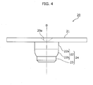
- FIG. 4 is a side view illustrating the structure of a sealing plug 20 according to the second embodiment of the present invention
- FIG. 5A and FIG. 5B are perspective views illustrating the structure of the sealing plug 20 according to the second embodiment of the present invention.
- FIG. 5A is a perspective view looking down at the sealing plug 20 from above a flange 21
- FIG. 5B is a perspective view looking up at the sealing plug 20 from below a tip 23.
- the sealing plug 20 is provided with the flange 21 having the same outer dimensions as the flange 11 according to the first embodiment, a base 22 having the same curved surface as the base 12, and the tip 23 which extends from the base 22.
- the thick portion 22a is formed having a cylindrical shape to the side of the base 22 near the flange 21, and the side surface portion 22b is formed having a curved surface to the side of the base 22 near the tip 23.
- the base 22 is formed having a structure which extends from the flange 21 to the thick portion 22a while maintaining a constant outer diameter, then gradually narrows in cross sectional area along the length of the side surface portion 22b to the tip 23.
- the thick portion 22a is formed in a cylindrical shape extending from an end of the base 22 opposite the tip 23 to an end of the side surface portion 22b.
- the outer edge of the portion of the base 22 between the end of the base 22 opposite the tip 23 and the end of the side surface portion 22b corresponds to the inner shape of the through hole.
- the outer diameter of the thick portion 22a is designed to have substantially the dimensions of the inner diameter of the through hole.
- the height of the thick portion 22a and the side surface portion 22b are substantially identical.
- the center of the upper surface of the flange 21 is provided with a truncated cone-shaped indentation 20a similar to the indentation 10a according to the first embodiment.
- each component of the sealing plug 20 is made out of metal and forms a concentric circle when viewed from the central axis D parallel to the length of the through hole.
- the tip 23 has a cylindrical shape which extends while maintaining the cross sectional shape of the tip end of the base 22 and has a length which is shorter than that of the base 22.
- the main shaft 24 of the sealing plug 20 is thickest at the cylindrical shaped thick portion 22a of the base 22, gradually narrows along the side surface portion 22b, and is the narrowest at the end of the base 22 nearest the tip 23 and at the tip 23.
- the side surface of the tip 23 is shown having a tapered edge, but the edge may be left non-tapered, made to be curved, or made to be any other given shape.
- FIG. 6 illustrates an advantageous result achieved by the sealing plug 20 according to the second embodiment of the present invention.
- the position of the tip 23 and the tip end of the base 22, which are sufficiently narrower than the inner diameter of the through hole 210, can be adjusted when the sealing plug 20 is inserted in the through hole 210.
- the through hole 210 is, for example, a fill hole for injecting the electrolyte into the container housing the energy storage element
- the sealing plug 20 is, for example, a fill plug for plugging the fill hole.
- the thick portion 22a which has substantially the same thickness as the inner diameter of the through hole 210, engages with the through hole 210, at which time the central axis D of the sealing plug 20 becomes parallel with the length of the through hole 210, whereby the sealing plug 20 assumes its stabilized proper position.
- the outer diameter of the thick portion 22a may be formed to be slightly smaller than the inner diameter of the through hole 210, and so long as the thick portion 22a can be inserted into the through hole 210, may be formed to be bigger than the inner diameter of the through hole.
- the sealing plug 20 according to the second embodiment with the base 22 and the tip 23 as the main shaft 24, the sealing plug 20 can be installed in a stable manner while keeping its proper position.
- the base 22 is formed from the cylindrical shaped thick portion 22a and the side surface portion 22b, and the outer shape of the thick portion 22a is formed to correspond to the inner shape of the through hole 210. This allows for the sealing plug 20 to be more securely provisionally fixed in the through hole 210 due to the thick portion 22a engaging with the through hole 210.
- the merits thereof are as follows.
- the provisionally fixed sealing plug engaged with the through hole is completely fixed to the container by laser welding.
- high-output laser welding there is concern that evaporation from the container, sealing plug, or filler material fused as a result of exposure to laser light will cause the sealing plug to jut out from the through hole, for example, thereby changing the position of the sealing plug from the provisionally fixed position, or further separate from the through hole.
- the output is set low when fixing the sealing plug to the container by laser welding in an effort to avoid this problem. In other words, a temporary fixing process is required.
- the thick portion 22a of the sealing plug 20 according to the second embodiment is engaged with the through hole 210, the position at the time of provisional fixing can be maintained even under high-output laser welding. As a result, the process of temporarily fixing the sealing plug 20 can be omitted, thereby improving battery manufacturability.
- the length of the thick portion 22a and the side surface portion 22b with respect to the center line D are substantially identical, but their lengths may be uneven. However, forming both to have substantially identical lengths is preferable for its provisional fixing stability and through hole engaging advantages.
- the thick portion 22a has a cylindrical shape and has a constant cross sectional shape throughout with respect to the central axis D.
- the structure of the thick portion 22a is not limited to this example, and may have a cross sectional shape which corresponds with a cross section perpendicular to the length-wise direction of the through hole 210.
- the thick portion 22a may be made to have a corresponding cross sectional shape.
- the side surface portion 22b in addition to the thick portion 22a of the base 22 may also be made to have a cross sectional shape which corresponds with the through hole 210.
- the tip 23 may also be made to have a cross sectional shape which corresponds with the through hole 210.
- a variation of the cross sectional shape of the base 22 and the tip 23 may be applied to the sealing plug 10 according to the first embodiment as well as the sealing plug 20 according to the second embodiment.
- FIG. 7A is a side view illustrating the structure of a sealing plug 30 according to the first variation of an embodiment of the present invention
- FIG. 7B is a perspective view illustrating the structure of the sealing plug 30 according to the first variation of an embodiment of the present invention.
- the sealing plug 30 shown in the side view of FIG. 7A and the perspective view of FIG. 7B is a variation of the sealing plug 10 according to the first embodiment. Similar to the sealing plug 10, in the sealing plug 30, a main shaft 34 is provided with a base 32 which includes a side surface portion 32d and a thick portion 32c formed at an interface of a flange 31.
- the side surface portion 32d is provided with a curved surface 32a formed on the side nearest a tip 33 which is similar to the curved surface of the side surface portion 12b of the sealing plug 10, and a tapered surface 32b formed on the side nearest the thick portion 32c.
- the base 32 has a cross section in a plane perpendicular to the central axis D having an area which is the smallest at the interface of the base 32 and the tip 33, and largest in the thick portion 32c at the interface of the base 32 and the flange 31
- the curved surface 32a and the tapered surface 32b of the base 32 differ in how the outer diameter with respect to the central axis D (length-wise direction) changes.
- the curved surface 32a has an outer diameter whose rate of change with respect to the position along the central axis D varies.
- the outline of the curved surface 32a is a curved line
- the tapered surface 32b has an outer diameter whose rate of change with respect to the position along the central axis D is constant.
- the outline of the tapered surface 32b is a straight line.
- the dimensions and shape of the flange 31 are the same as those of the flange 11 of the sealing plug 10 and the flange 21 of the sealing plug 20 according to the first and second embodiments, respectively, and the characteristic features (curved surface and cylindrical shape) of the outer shapes of each of the base 32 and the tip 33 are the same as the base 12 and the tip 13 of the sealing plug 10 and the base 22 and the tip 23 of the sealing plug 20.
- the sealing plug 30 having the above-described structure is a preferable structure for a through hole 220 having a tapered cross section.
- FIG. 8 illustrates an advantageous result achieved by the sealing plug 30 according to the first variation of an embodiment of the present invention.
- the tip 33 of the sealing plug 30 is inserted into the through hole 220 the same as with the first and second embodiments described above.
- the through hole 220 is, for example, a fill hole for injecting the electrolyte into the container housing the energy storage element
- the sealing plug 30 is, for example, a fill plug for plugging the fill hole.
- the curved surface 32a of the base 32 first comes into contact with a rim 221 of the through hole 220, then the tapered surface 32b engages with the through hole 220.
- the sealing plug 30 is provisionally fixed in the through hole 220 while assuming a proper position, that is, while the central axis D is parallel to the length-wise direction of the through hole 220.
- the structure of the base 32 may take on any given shape as long as the shape corresponds with the shape of the through hole 220 which the sealing plug 30 seals.
- the present invention is therefore advantageous in that it can be applied to through holes of various shapes.
- the whole surface of the side surface portion 12b of the base 12 as well as the side surface portion 22b of the base 22 is a curved surface having an outer diameter whose rate of change with respect to the position along the central axis D varies.
- a portion of the side surface portion 32d is formed as a tapered surface having a constant rate of change with respect to position along the central axis D.
- FIG. 9A and FIG. 9B show yet another variation.
- FIG. 9A is a side view illustrating the structure of a sealing plug 40 according to the second variation of an embodiment of the present invention
- FIG. 9B is a perspective view illustrating the structure of the sealing plug 40 according to the second variation of an embodiment of the present invention.
- the sealing plug 40 shown in the side view of FIG. 9A and the perspective view of FIG. 9B is a variation of the sealing plug 20 according to the second embodiment. Similar to the sealing plug 20, in the sealing plug 40, a main shaft 44 is provided with a base 42 which includes a side surface portion 42b and a cylindrical thick portion 42a formed at an interface of a flange 41.
- the side surface portion 42b is provided with a curved surface 42b1 formed on the side nearest the thick portion 42a, and a tapered surface 42b2 formed on the side nearest a tip 43.
- the curved surface 42b1 is a curved surface that is thickest at the end nearest the thick portion 42a, and thinnest at the end nearest the tapered surface 42b2.
- a rate of change in outer circumference of a cross section in a plane perpendicular to the axial direction of the main shaft 44 varies.
- the outer diameter of the base 42 gradually narrows from the curved surface 42b1 to the tapered surface 42b2, and similar to the second embodiment, the tip 43 and the base 42 maintain dimensions which allow them to be adjusted inside the through hole upon insertion. It is to be noted that in the Drawings, the outline of the base 22 according to the second embodiment is drawn with a dashed line for comparison.
- the portion of the side surface portion 42b of the base 42 nearest the flange 41, which is the portion of the side surface portion 42b which has the largest diameter, is the portion which is most likely to come in contact with the rim of the through hole when the sealing plug 40 is placed in the through hole, similar to the base 22 according to the second embodiment as shown in (a) and (b) of FIG. 6 , for example.
- the base 42 being formed having a curved surface (that is, the rate of change in the outer diameter varies) in at least this portion, contamination from contact can be reduced and the tip 43 and the base 42 can be smoothly inserted into the through hole.
- the sealing plug 40 including the base 42 is based on the sealing plug 20 according to the second embodiment, but the variation may be applied to the sealing plug 10 according to the first embodiment as well.
- the curved surface 42b1 is formed to the side nearest the thick portion 42a and the tapered surface 42b2 is formed to the side nearest the tip 43, but the relationship between the curved surface and the tapered surface can be reversed.
- the side surface of the tip 43 is shown in the Drawings as having a tapered edge, but the edge may be left non-tapered, made to be curved, or made to be any other given shape.
- the base 42 is acceptable as long as it includes the thick portion 42a and the curved surface 42b1, but the base 42 is not limited to a specific aspect of the curved surface 42b1.
- the change in the curvature of the curved surface 42b1 is based on the variation in the outer diameter of the base 42, that is, based on the fact that the base 42 has a circular cross sectional shape in a plane perpendicular to the length-wise direction of the through hole.
- the is elliptical, oval, or any other given shape may be based on the variation in circumference
- FIG. 10 is a side view illustrating the structure of a sealing plug 50 according to the third variation of an embodiment of the present invention.
- the sealing plug 50 is provided with a base 52 and a tip 53, and the base 52 is provided with a thick portion 52a and two side surface portions, a side surface portion 52b and a side surface portion 52c.
- the side surface portion 52b has the same structure as the side surface portion 22b according to the second embodiment, and the side surface portion 52c is provided directly below a flange 51 and has the shape of a truncated cone.
- the side surface portion 52c has an outer edge (cross sectional area) in a plane parallel to the axial direction of a main shaft 54 that is smaller than that of the thick portion 52a. It is to be noted that in FIG. 10 , the outline of the thick portion 22a according to the second embodiment is drawn with a dashed line for comparison. It is to be noted that the side surface portion 52c is formed between the flange 51 and the thick portion 52a and has a cross sectional area that is less than a cross sectional area of the thick portion 52a.
- the base 52 has a side surface formed between the end of the base 52 opposite the tip 53 and the thick portion 52a, the side surface having, in a plane perpendicular to the axial direction of the main shaft 54, a cross section having an outer edge that is smaller than a corresponding outer edge of the thick portion 52a.
- the position of the tip 53 and the base 52 included in the main shaft 54 can be adjusted inside the through hole upon insertion. Moreover, engagement with the through hole can be achieved due to the inclusion of the thick portion 52a in the base 52, and the same advantageous results as the second embodiment can be achieved due to the use of the side surface portion 52b and the tip 53.
- FIG. 11 is a side view illustrating the structure of a sealing plug 60 according to the fourth variation of an embodiment of the present invention.
- the sealing plug 60 may be provided with a tip 63 which is longer than a side surface portion 62b of a base 62. In this case as well, by placing the center of gravity G of a main shaft 64 lower than the base 62 including a thick portion 62a, the sealing plug 60 can rapidly assume its proper position.
- the radius of the thick portion 62a is made to be shorter than the overall length of the main shaft 64.
- the radius of the thick portion 62a is shorter than the longest line (line L2) of the possible straight lines connecting the center C2 of the bottom surface of the thick portion 62a that is nearest the side surface portion 62b and the tip end surface of the tip 63, sufficient control of tilt and rotation about the axis can be achieved.
- FIG. 11 is not intended to be limiting.
- the thick portion is made to have thickness in the length-wise direction, such as is the case in the sealing plug 20 according to the second embodiment, sufficient control of tilt and rotation about the axis can be achieved as a result of constant placement of the center of gravity near the tip.
- the radius of the thick portion 62a is shorter than a longest straight line connecting (i) a center of an end surface of the base 62 opposite the tip 63 or a center of an interface of the thick portion 62a and the side surface portion 62b, and (ii) an leading end surface of the tip 63.
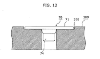
- FIG. 12 is a side view illustrating the structure of a sealing plug 70 according to the fifth variation of an embodiment of the present invention.
- a through hole 310 is formed recessed into a wall 300.
- the through hole 310 includes a portion with a large diameter into which a flange 71 is inserted, and a small portion into which a main shaft 74 is inserted, resulting in the entire body of the sealing plug 70 being positioned inside the through hole 310.
- the sealing plug 70 is shown as the sealing plug 10 according to the first embodiment, but the sealing plug according to the first or second embodiment, or any of the above variations, may be used as the sealing plug 70.
- FIG. 13 is a side view illustrating the structure of a sealing plug 80 according to the sixth variation of an embodiment of the present invention. As is shown in FIG. 13 , the sealing plug 80 is not provided with a flange.
- the sealing plug is provided with a main shaft 84 which includes a base 82 and a tip 83. A through hole 210 is sealed with the main shaft 84.
- the shape of the main shaft according to the first or second embodiment, or any of the above variations, may be used as the shape of the sealing plug 80.
- FIG. 14 is a side view illustrating the structure of a sealing plug 90 according to the seventh variation of an embodiment of the present invention. As is shown in FIG. 14 , in the sealing plug 90, a flange 91 is formed having a through hole, and a main shaft 94 is formed having an indentation.
- the shape of the hollowed portion formed in the sealing plug 90 is not limited to this example.
- the sealing plug 90 may be formed having an indentation or through hole in only the main shaft 94 instead of the through hole being formed in the flange 91.
- the shape of the sealing plug according to the first or second embodiment, or any of the above variations may be used as the shape of the sealing plug 90.
- the sealing plug according to the present invention is provided with a main shaft having a base and a tip with an outer edge that is smaller than or equal to the outer edge of the base, and the base includes a thick portion having the largest outer edge and a side surface portion whose outer edge decreases in size in a direction towards the tip, the advantageous effects thereof can be achieved, and the sealing plug is not limited by structural details of other members or portions.
- FIG. 15 is an exploded perspective view illustrating a typical structure of a non-aqueous electrolyte secondary battery according to the third embodiment of the present invention which uses a sealing plug.
- a non-aqueous electrolyte secondary battery 110 is an example of an energy storage element provided with a battery case, which includes a box-shaped container 112 having an opening 112a and a plate shaped cover 111 made of aluminum, and an electrode assembly 112d housed therein.
- the electrode assembly 112b housed inside the container 112 is an electrode assembly including, wound into an oblong shape, a belt shaped positive electrode, a belt shaped negative electrode, and a separator interposed between the positive electrode and the negative electrode.
- the positive electrode and the negative electrode are positioned in different directions along the axial direction of the winding, and the ends of the positive electrode and the negative electrode are positioned at respective ends of the electrode assembly 112b.
- an active material is not coated at the ends of each electrode, where the metallic foil base material is exposed.
- Conductive metal plate current collectors 112c and 112c' positioned at corresponding positive and negative electrode sides are connected to the metallic foil protruding out from each end of the electrode assembly 112b.
- positive and negative electrode terminals 111a and 111a' to which an external load can be detachably attached are provided on the surface of the cover 111 and electrically and mechanically connected to the electrode assembly 112b. Furthermore, a through hole 111b is opened in the surface of the cover 111 which corresponds to the through hole 210 according to the first embodiment or the through hole 220 according to the second embodiment.
- the non-aqueous electrolyte secondary battery 110 is assembled as described below.
- the electrode terminals 111a and 111a' are fixed to the surface of the cover 111, and the current collectors 112c and 112c' are connected to the electrode terminals 111a and 111a', respectively, from the underside of the cover 111 via a conductive connecting material (not shown in the Drawings), whereby the cover 111 and the electrode assembly 112b are assembled as one.
- the electrode assembly 112b is inserted into the opening 112a, and the container 112 is covered with the cover 111.
- the battery case is then completed by welding the joining areas.
- an electrolyte is injected into the container 112 via the through hole 111b, and after a formation process is performed by running electricity through the electrode terminals 111a and 111a', the through hole 111b is sealed with a sealing plug 113, thereby completing the assembly of the non-aqueous electrolyte secondary battery 110.
- the sealing plug 113 is made of aluminum, but it is preferable that the sealing plug 113 be made of a material that is softer than the battery case.
- Manufacturability of the above-described non-aqueous electrolyte secondary battery 110 is improved as a result of the increased efficiency of the manufacturing processes relating to the sealing plug when the sealing plug according to the present invention exemplified by the sealing plugs 10 through 90 according to the first and second embodiments, is used as the sealing plug 113.
- the through hole is provided in a wall which is the cover 111, but the through hole may be provided in a wall on the side of the container 112.
- the through hole can be formed flexibly according to the design of the battery.
- the non-aqueous electrolyte secondary battery 110 as typified by the lithium-ion secondary battery is presented for exemplary purposes as the energy storage element.
- the battery is a battery capable of being recharged via electrochemical reaction
- any other type of secondary battery such as a nickel hydride battery may be used.
- the non-aqueous electrolyte secondary battery 110 may be a primary battery.
- the non-aqueous electrolyte secondary battery 110 may be an element which directly stores electricity as a charge, such as an electric double layer capacitor.
- the energy storage element according to the present invention is an element capable of storing electricity, it is not limited to a specific means.
- the housing provided with the sealing plug 113 is an energy storage element battery case including the cover 111 and the container 112.
- the housing may be used to store a liquid such as fuel or a chemical, or a powder substance.
- the housing is not limited by the application, quality of material, or shape thereof, and so as long as the housing includes a wall in which a through hole is formed and sealed with a sealing plug, the housing may be a hermetically sealed housing, a housing having an opening, or a housing having a flat or rounded plate-shaped portion.
- the sealing plug is made of aluminum, but may be made of an aluminum alloy, copper, stainless steel, or any other metal or compound metal.
- the sealing plug is not limited by the material it is made of.
- the sealing plug may be ceramic or constructed of a plastic material.
- the sealing plug may be made of a different material than the wall in which the through hole is provided.
- the present invention is applicable as a sealing plug capable of being installed in a container in a stable manner, or as an energy storage element such as a non-aqueous electrolyte secondary battery which uses such a sealing plug.
Landscapes
- Chemical & Material Sciences (AREA)
- Chemical Kinetics & Catalysis (AREA)
- Electrochemistry (AREA)
- General Chemical & Material Sciences (AREA)
- Engineering & Computer Science (AREA)
- Materials Engineering (AREA)
- Manufacturing & Machinery (AREA)
- Filling, Topping-Up Batteries (AREA)
- Sealing Battery Cases Or Jackets (AREA)
- Connector Housings Or Holding Contact Members (AREA)
Abstract
Description
- The present application is based on and claims priority of Japanese Patent Application No.
2011-235369 filed on October 26, 2011 2012-208359 filed on September 21, 2012 - The present invention relates to a sealing plug for a container acting as the housing for an energy storage element such as a secondary battery or other type of battery, and to an energy storage element which uses the sealing plug.
- In addition to use as a replacement for primary batteries, secondary batteries are widely used as a source of power for electrical devices such as cellular telephones and information technology devices. In particular, non-aqueous electrolyte secondary batteries exemplified by the lithium-ion battery continue to be widely used in electric vehicles and other industrial large scale electronic devices for their high energy density characteristics.
- This particular type of secondary battery generally includes an electrode assembly and an electrolyte housed in a container made of metal such as aluminum. The container, which has a prefabricated through hole in a surface thereof, is hermetically sealed after housing the electrode assembly. The electrolyte is then injected into the container via the through hole. Next, the through hole is sealed with a sealing plug made of metal to preserve the hermetically sealed state of the container (for example, see Patent Literature (PTL) 1).
-
FIG. 16A is a side view of a secondary batterycontainer sealing plug 100 having the conventional structure recited inPTL 1,FIG. 16B is a perspective view of thesealing plug 100, andFIG. 16C is a cross-sectional view of the sealing plug 100 (a cross-sectional view showing thesealing plug 100 sliced in a plane including the central axis D shown inFIG. 16A ).FIG. 17A shows thesealing plug 100 when it is placed in the throughhole 210. - As shown in these Drawings, the
sealing plug 100 includes abase 102 which engages with a throughhole 210 formed in awall 200, and aflange 101 which locks to the surface of thewall 200. Thesealing plug 100 is formed having a smooth,curved surface 103 on the edge of the tip of thebase 102. Thecurved surface 103 is the portion most likely to come in contact with arim 211 of thethrough hole 210. Since themetallic base 102 smoothly inserts into the throughhole 210, contamination, such as metal residue resulting from two parts coming into contact, can be reduced. - [PTL 1] Japanese Patent No.
4110632 - However, the conventional sealing plug is problematic as there is a concern that manufacturability will be compromised due to poor stability of the sealing plug upon installation. The present invention has been made in view of the above problem, and an object of the present invention is to provide a sealing plug capable of being installed in a through hole in a stable manner and provide an energy storage element which uses such a sealing plug.
- In order to achieve the above goal, a sealing plug according to an aspect of the present invention seals a through hole formed in a wall, the sealing plug comprising: a main shaft which is placeable in the through hole, wherein the main shaft includes: a base; and a tip connected to a leading end of the base and having a cross section having an outer edge that is smaller than or equal to an outer edge of a cross section of the leading end of the base, the cross sections each being in a plane perpendicular to an axial direction of the main shaft, and the base includes: a thick portion having, in a plane perpendicular to the axial direction of the main shaft, a cross section having a largest outer edge; and a side surface portion having an outer edge which decreases in size from the thick portion towards the tip.
- With this, since the main shaft of the sealing plug is shaped such that an outer edge of a cross section thereof decreases in size from the thick portion of the base to the tip of the base, the main shaft can easily be inserted into the through hole and the sealing plug can be provisionally fixed while maintaining a proper position. As a result, this sealing plug can be stably installed in the through hole.
- Moreover, the thick portion may be provided at an end of the base opposite the tip and positioned at a rim of the through hole when the sealing plug seals the through hole.
- With this, since the thick portion, which has the largest outer edge dimensions, is positioned at the rim of the through hole, contact between the main shaft and the rim and contamination resulting therefrom can be reduced when the main shaft is inserted into the through hole.
- Moreover, the thick portion may be formed in a cylindrical shape extending from an end of the base opposite the tip to an end of the side surface portion.
- With this, since the thick portion is formed in a cylindrical shape, the sealing plug can be more securely provisionally fixed in the through hole due to the thick portion engaging with the through hole. As a result, manufacturability can be improved by omitting a fixing process to fix the sealing plug to the container by low-output laser welding.
- Moreover, along at least a portion of the side surface portion, a rate of change in outer circumference of a cross section in a plane perpendicular to the axial direction of the main shaft may vary.
- With this, the main shaft is shaped such that the rate of change in outer circumference from the thick portion toward the tip varies, in other words, is shaped such that, along at least a portion of the surface, the outer edge of a cross section in a plane parallel to the axial direction of the main shaft is a curved line. As a result, contamination, resulting from contact between the main shaft and the rim and inside of the through hole, can be reduced upon insertion of the main shaft into the through hole.
- Moreover, an exposed portion may be connected to an end of the base opposite the tip and positioned, when the sealing plug seals the through hole, on a surface of the wall so as to be exposed from the wall.
- With this, due to the exposed portion being exposed above the surface of the wall when the sealing plug seals the through hole, the sealing plug can be easily inserted and stably installed in the through hole.
- Moreover, an outer shape of a portion of the base between an end of the base opposite the tip and an end of the side surface portion may correspond to an inner shape of the through hole.
- With this, since the outer shape of a portion on the base end of the base corresponds with the inner shape of the through hole, the sealing plug can be more securely provisionally fixed in the through hole due to the portion on the base end engaging with the through hole. As a result, the process of temporarily fixing the sealing plug can be omitted, and manufacturability can be improved.
- Moreover, a distance from a leading end of the tip to the base may be greater than a distance from the leading end of the tip to a center of gravity of the main shaft.
- With this, due to the center of gravity of the main shaft being positioned closer to the tip than the base, the sealing plug can rapidly assume its proper position upon insertion into the through hole.
- Moreover, the tip may be longer than the base in the axial direction of the main shaft.
- With this, due to the main shaft being formed such that the tip is longer than the base, the sealing plug can rapidly assume its proper position upon insertion into the through hole.
- Moreover, when the sealing plug seals the through hole, a length of the main shaft in the axial direction may be less than or equal to a length of the through hole in the axial direction.
- With this, due to the length of the main shaft being shorter than or equal to the length of the through hole, the main shaft will not protrude out from the bottom of the through hole, and the sealing plug will not penetrate into the housing space beyond the wall.
- Moreover, a radius of the thick portion may be shorter than a longest straight line connecting (i) a center of an end surface of the base opposite the tip or a center of an interface of the thick portion and the side surface portion, and (ii) a leading end surface of the tip.
- With this, since the radius of the thick portion is shorter than the longest straight line connecting (i) the center of the end surface of the base end of the base or the center of the end of the thick portion towards the side surface portion, and (ii) the leading end surface of the tip, even if the sealing plug rotates upon insertion into the through hole, this rotation is inhibited by the tip.
- Moreover, the base may have a side surface formed between an end of the base opposite the tip and the thick portion, and formed to have a cross section having an outer edge that is smaller than an outer edge of a cross section of the thick portion, the cross sections each being in a plane perpendicular to the axial direction of the main shaft.
- With this, the base may be shaped having a portion whose outer edge is smaller than the thick portion formed more towards the base end than the thick portion. Even in this case, the main shaft can be easily inserted into the through hole, and the sealing plug can be stably installed in the through hole.
- Moreover, in order to achieve the above goal, an energy storage element according to an aspect of the present invention comprises: a container having an opening; a cover which covers the opening; an electrode assembly housed in the container; and the above-described sealing plug, wherein the container or the cover is provided with a wall in which a through hole is formed, and the sealing plug seals the through hole formed in the wall.
- With this, since the through hole formed in the wall of the energy storage element is plugged with the above-described sealing plug, similar to the above description, the energy storage element in which the sealing plug is stably installed in the through hole can be achieved.
- These and other objects, advantages and features of the invention will become apparent from the following description thereof taken in conjunction with the accompanying drawings that illustrate a specific embodiment of the present invention.
- [
FIG. 1] FIG. 1 is a side view illustrating the structure of the sealing plug according to the first embodiment of the present invention. - [
FIG. 2A] FIG. 2A is a perspective view illustrating the structure of the sealing plug according to the first embodiment of the present invention. - [
FIG. 2B] FIG. 2B is a perspective view illustrating the structure of the sealing plug according to the first embodiment of the present invention. - [
FIG. 3] FIG. 3 illustrates an advantageous result achieved by the sealing plug according to the first embodiment of the present invention. - [
FIG. 4] FIG. 4 is a side view illustrating the structure of the sealing plug according to the second embodiment of the present invention. - [
FIG. 5A] FIG. 5A is a perspective view illustrating the structure of the sealing plug according to the second embodiment of the present invention. - [
FIG. 5B] FIG. 5B is a perspective view illustrating the structure of the sealing plug according to the second embodiment of the present invention. - [
FIG. 6] FIG. 6 illustrates an advantageous result achieved by the sealing plug according to the second embodiment of the present invention. - [
FIG. 7A] FIG. 7A is a side view illustrating the structure of the sealing plug according to the first variation of an embodiment of the present invention. - [
FIG. 7B] FIG. 7B is a perspective view illustrating the structure of the sealing plug according to the first variation of an embodiment of the present invention. - [
FIG. 8] FIG. 8 illustrates an advantageous result achieved by the sealing plug according to the first variation of an embodiment of the present invention. - [
FIG. 9A] FIG. 9A is a side view illustrating the structure of the sealing plug according to the second variation of an embodiment of the present invention. - [
FIG. 9B] FIG. 9B is a perspective view illustrating the structure of the sealing plug according to the second variation of an embodiment of the present invention. - [
FIG. 10] FIG. 10 is a side view illustrating the structure of the sealing plug according to the third variation of an embodiment of the present invention. - [
FIG. 11] FIG. 11 is a side view illustrating the structure of the sealing plug according to the fourth variation of an embodiment of the present invention. - [
FIG. 12] FIG. 12 is a side view illustrating the structure of the sealing plug according to the fifth variation of an embodiment of the present invention. - [
FIG. 13] FIG. 13 is a side view illustrating the structure of the sealing plug according to the sixth variation of an embodiment of the present invention. - [
FIG. 14] FIG. 14 is a cross-sectional view illustrating the structure of the sealing plug according to the seventh variation of an embodiment of the present invention. - [
FIG. 15] FIG. 15 is an exploded perspective view illustrating a typical structure of a non-aqueous electrolyte secondary battery according to the third embodiment of the present invention which uses the sealing plug. - [
FIG. 16A] FIG. 16A is a side view illustrating the structure of a conventional sealing plug. - [
FIG. 16B] FIG. 16B is a perspective view illustrating the structure of a conventional sealing plug. - [
FIG. 16C] FIG. 16C is a cross-sectional view illustrating the structure of a conventional sealing plug. - [
FIG. 17A] FIG. 17A illustrates a conventional sealing plug inserted into the through hole. - [
FIG. 17B] FIG. 17B illustrates a problem with the conventional sealing plug. - Problems related to the conventional structure of the sealing
plug 100 as described above will be described hereinafter. - When the through
hole 210 is sealed with the sealingplug 100, it is necessary to insert and provisionally fix the base 102 into the throughhole 210. However, when the sealingplug 100 is actually placed in the throughhole 210 by hand or with a tool, for example, the sealingplug 100 tilts at an angle with respect to the throughhole 210, as shown inFIG. 17B. FIG. 17B illustrates the problem with theconventional sealing plug 100. - As a result of this tilting, even if there were a large margin between the outer diameter of the
base 102 and the inner diameter of the throughhole 210, thecurved surface 103 of the base 102 would slip on therim 211 of the throughhole 210 and the side of the base 102 would get stuck on therim 211 of the throughhole 210. Consequently, the success rate of placing the sealingplug 100 in the throughhole 210 in a stabilized position decreases. - In order to provisionally fix the sealing
plug 100 it is necessary to readjust the positioning of the sealingplug 100. This considerably reduces workability and manufacturability in the making of the secondary battery. - The conventional sealing plug is problematic because there is a concern that manufacturability will be compromised due to poor stability of the sealing plug upon installation.
- The present invention has been made in view of the above problem, and an object of the present invention is to provide a sealing plug capable of being installed in a through hole in a stable manner and an energy storage element which uses such a sealing plug.
- Hereinafter, embodiments of present invention are described with reference to the Drawings. Each of the exemplary embodiments described below shows a general or specific example. The numerical values, shapes, materials, structural elements, the arrangement and connection of the structural elements etc. shown in the following exemplary embodiments are mere examples, and therefore do not limit the scope of the appended Claims and their equivalents. Therefore, among the structural elements in the following exemplary embodiments, structural elements not recited in any one of the independent claims are described as arbitrary structural elements.
-
FIG. 1 is a side view illustrating the structure of a sealingplug 10 according to the first embodiment of the present invention. - As
FIG. 1 shows, the sealingplug 10 is a sealing plug which seals a through hole formed in a wall, and similar to the conventional example, is made out of aluminum and forms a concentric circle when viewed from the central axis D parallel to the length of the through hole. The sealingplug 10 includes aflange 11 and amain shaft 14, and themain shaft 14 includes abase 12 and atip 13. - Similar to the
conventional flange 101, theflange 11 is disk-shaped, directly seals the through hole, and is connected to the end of the base 12 opposite the tip 13 (shown as on the top inFIG. 1 ). According to the first embodiment, theflange 11 is an exposed portion positioned on a surface of the wall so as to be exposed from the wall when the through hole is sealed by the sealingplug 10. It is to be noted that the shape of theflange 11 is not limited to a disk, but may be a rectangular plate, for example. Moreover, theflange 11 is intended to be included in the exposed portion recited in the Claims. - The
main shaft 14 is a portion which is placeable in the through hole and is formed to have a length in the axial direction (central axis D) that is less than or equal to the length of the through hole in the axial direction when the through hole is sealed by the sealingplug 10. Hereinafter, thebase 12 and thetip 13 included in themain shaft 14 will be described in detail. - The
base 12 is positioned at the base end of themain shaft 14 closer to the flange 11 (shown as on the top inFIG. 1 ), and has dimensions that allow the base 12 to be inserted in the through hole. Specifically, thebase 12 is formed to have round cross section in a plane perpendicular to the axial direction of themain shaft 14. Moreover, the distance from a leading end of thetip 13 to thebase 12 is greater than the distance from the leading end of thetip 13 to a center of gravity (G inFIG. 1 ) of themain shaft 14. Specifically, the center of gravity G of themain shaft 14 is located outside of the base 12 (shown as below the base 12 inFIG. 1 ). - The
tip 13 is a cylindrical body connected to the tip end of thebase 12. That is, thetip 13 is formed having a cross section in a plane perpendicular to the axial direction of themain shaft 14 which has an outer edge that is the same round shape throughout and has the same dimensions throughout. Moreover, thetip 13 is formed having a cross section in a plane perpendicular to an axial direction of themain shaft 14 which has an outer edge that is smaller than or equal to a corresponding outer edge of the tip of thebase 12. It is to be noted that, in the Drawings, the side surface of thetip 13 is shown having a tapered edge, but the edge may be left non-tapered, made to be curved, or made to be any other given shape. - Next, the
base 12 will be described in detail.FIG. 2A and FIG. 2B are perspective views illustrating the structure of the sealingplug 10 according to the first embodiment of the present invention. Specifically,FIG. 2A is a perspective view looking down at the sealingplug 10 from above theflange 11, andFIG. 2B is a perspective view looking up at the sealingplug 10 from below thetip 13. - As is shown in
FIG. 1 andFIG. 2A , the center of the upper surface of theflange 11 is provided with a truncated cone-shapedindentation 10a which is used as a laser welding marker. - Moreover, as is shown in
FIG. 1 andFIG. 2B , thebase 12 is provided at an end of themain shaft 14 opposite thetip 13 and includes athick portion 12a having, in a plane perpendicular to an axial direction of themain shaft 14, a cross section having the largest outer edge of thebase 12. In the first embodiment, thethick portion 12a is provided at an interface of theflange 11 which is an end portion formed at the base end of thebase 12, and has the largest diameter and cross section area in themain shaft 14. Moreover, when the sealingplug 10 plugs the through hole, thethick portion 12a is positioned at the rim of the through hole. - Moreover, the portion of the base 12 having the smallest diameter is formed at the end of the tip end of the
base 12, at the interface with thetip 13. Thebase 12 has a side surface which substantially has the shape of a truncated cone with a curved surface. - In other words, the
base 12 has aside surface portion 12b which has an outer edge which decreases in size from thethick portion 12a towards thetip 13. According to the first embodiment, along the entire surface of theside surface portion 12b, a rate of change in outer circumference of a cross section in a plane perpendicular to the axial direction of themain shaft 14 varies. In other words, thebase 12 has an outer diameter which becomes smaller from thethick portion 12a near theflange 11 towards thetip 13 as the rate of change varies gradually. Consequently, the cross section of the base 12 in a plane including the central axis D has a curved contour, as is shown inFIG. 1 . - Moreover, the outer diameter of the
thick portion 12a is formed to have substantially the dimensions of the inner diameter of the through hole. It is to be noted that the outer diameter of thethick portion 12a may be formed to be slightly smaller than the inner diameter of the through hole, and so long as thethick portion 12a can be inserted into the through hole, may be formed to be bigger than the inner diameter of the through hole. - Moreover, the
tip 13 is longer than the base 12 in the axial direction of themain shaft 14. Specifically, using the central axis D as a reference, the height of thetip 13 is approximately twice the height of thebase 12. - Moreover, the radius of the
thick portion 12a is shorter than a longest straight line connecting (i) a center of an end surface of the base 12 opposite thetip 13 or a center of an interface of thethick portion 12a and theside surface portion 12b, and (ii) a leading end surface of the tip13. According to the first embodiment, the radius of thethick portion 12a is shorter than the overall height of themain shaft 14, that is, shorter than the distance from thethick portion 12a to the tip end of thetip 13. - In this way, the sealing
plug 10 according to the first embodiment is characterized by being provided with, as themain shaft 14, (i) thebase 12 having a substantially truncated cone shape whose cross section has an outer edge which becomes smaller towards the tip, and (ii) thetip 13 at the tip end of thebase 12. - Hereinafter, the efficacy of the plugging, with the sealing
plug 10, of the throughhole 210 opened in thewall 200 of the metallic container holding a energy storage element such as a secondary battery, will be explained with reference to main component cross-sectional views shown in (a) through (c) inFIG. 3. FIG. 3 illustrates an advantageous result achieved by the sealingplug 10 according to the first embodiment of the present invention. - As is shown in (a) in
FIG. 3 , in the sealingplug 10, the thickness of thetip 13 is the same as the thinnest portion of thebase 12. In other words, thetip 13 is thinner than the inner diameter of the throughhole 210. For this reason, when the sealingplug 10 is held by hand or with a tool, the position of thetip 13 can be adjusted as it is inserted in the throughhole 210, thereby preventing positional deviation of thebase 12. Here, the throughhole 210 is, for example, a fill hole for injecting the electrolyte into the container housing the energy storage element, and the sealingplug 10 is, for example, a fill plug for plugging the fill hole. - As is shown in (b) in
FIG. 3 , when the sealingplug 10 is inserted further deeper into the throughhole 210, the side surface of thebase 12 comes into contact with therim 211, which is the edge of the opening of the throughhole 210. Due to the curved surface of thebase 12, the base 12 slips deep into the throughhole 210 along therim 211. Since, similar to thetip 13, the portion of the base 12 from the tip end to the base end has a diameter that is sufficiently smaller than the inner diameter of the throughhole 210, thebase 12 and thetip 13 can change position inside the throughhole 210 while being inserted. For this reason, the sealingplug 10 is inserted until the base end of the base 12 having substantially the dimensions of the inner diameter of the throughhole 210 engages the throughhole 210, that is, until thethick portion 12a engages the throughhole 210. - Finally, as is shown in (c) in
FIG. 3 , thebase 12 is engaged with the throughhole 210 with thethick portion 12a, whereby theflange 11 completely covers the throughhole 210 and the provisional fixing of the sealingplug 10 in the throughhole 210 is complete. The sealingplug 10 is maintained at a proper position in which the central axis D of the sealingplug 10 is parallel with the length of the throughhole 210 when the provisional fixing is complete. - As described above, with the sealing
plug 10 according to the present invention, themain shaft 14 is shaped such that the outer edge of a cross section of themain shaft 14 becomes smaller from thethick portion 12a of the base 12 to thetip 13. In other words, themain shaft 14 is provided with the base 12 having a substantially truncated cone shape with a curved side surface and thetip 13 extending from thebase 12. This allows themain shaft 14 to be easily inserted into the throughhole 210 and the sealingplug 10 to be provisionally fixed while maintaining a proper position. Consequently, the sealingplug 10 can be installed in the throughhole 210 in a stable manner. - Moreover, the
main shaft 14 is shaped such that the rate of change of the outer circumference thereof varies from thethick portion 12a towards thetip 13. In other words, the side surface of thebase 12 is formed to have a curved surface. Consequently, contamination upon insertion of themain shaft 14 into the throughhole 210 resulting from contact between the sealingplug 10 and the inside of the throughhole 210 or therim 211 can be inhibited. - Moreover, due to the
flange 11 being exposed from the surface of thewall 200 when the sealingplug 10 seals the throughhole 210, the sealingplug 10 can be easily inserted and stably installed in the throughhole 210. - Moreover, due to the
thick portion 12a, which has the largest outer edge, being positioned at therim 211 of the throughhole 210 when themain shaft 14 is inserted into the throughhole 210, contact between themain shaft 14 and therim 211 and contamination resulting therefrom can be reduced. - Moreover, due to the
main shaft 14 being formed such that thetip 13 is longer than the base 12, the sealingplug 10 can rapidly assume its proper position upon insertion into the throughhole 210. - Moreover, due to the length of the
main shaft 14 being shorter than or equal to the throughhole 210, themain shaft 14 will not protrude out from the bottom of the throughhole 210, meaning the sealingplug 10 will not penetrate into the housing space beyond thewall 200. - Moreover, the radius of the
thick portion 12a is shorter than a longest straight line connection (i) the center of the end surface of the base end of the base 12 or the center of the end of thethick portion 12a on the side surface portion side and (ii) the leading end surface of thetip 13. Specifically, in the sealingplug 10, the length of themain shaft 14 including thebase 12 is longer than the radius of thethick portion 12a. For this reason, when the sealingplug 10 is inserted into the throughhole 210, excessive tilting of the sealingplug 10 with respect to the length-wise direction of the throughhole 210 can be prevented, and the sealingplug 10 can be restrained from rotating about its axis inside the throughhole 210. Consequently, the sealingplug 10 can be inserted into the throughhole 210 in a stabilized manner. - It is to be noted that in the preceding description, the position of the sealing
plug 10 shown in (b) inFIG. 3 is that of the sealingplug 10 being held by hand or with a tool while being inserted. However, even if the sealingplug 10 is released in this position, thebase 12 will settle down into the throughhole 210 due to the weight of thetip 13, and the base end surrounding thebase 12 will engage with therim 211 after the side surface of the base 12 slides along therim 211 of the throughhole 210. Therefore the provisionally fixed state shown in (c) inFIG. 3 is the same as when the sealingplug 10 is inserted. As is shown inFIG. 1 , since the center of gravity G of themain shaft 14 is closer to thetip 13 than the base 12 including thethick portion 12a (shown as further to the bottom in the Drawings), the sealingplug 10 can rapidly assume its proper position upon insertion into the throughhole 210, which is preferable especially in this kind of situation. - In the above description, the radius of the
thick portion 12a is shorter than the overall height of themain shaft 14, that is, shorter than the distance from thethick portion 12a to the tip end of thetip 13. However, as is shown inFIG. 1 , as long as the radius of thethick portion 12a is shorter than the longest line (line L1) of the possible straight lines connecting the center of thethick portion 12a C1 and the tip end surface of thetip 13, sufficient control of tilt and rotation about the axis can be achieved. - Moreover, in the above description, the
side surface portion 12b is formed having a curved surface whose rate of change in cross section circumference varies. However, theside surface portion 12b may be formed to have a surface whose rate of change in circumference is constant. In other words, the contour of a cross section of a plane including the central axis of the base 12 may be a sloped straight line. Even when this is the case, the advantageous result in which themain shaft 14 can be easily inserted into the throughhole 210 and the sealingplug 10 can be installed in the throughhole 210 in a stable manner can be achieved. - Moreover, the outer edge of a cross section of the
base 12 and thetip 13 included in themain shaft 14 is not limited to a circular shape, but may be an elliptical shape or a rectangular shape. - A sealing
plug 20 according to the second embodiment of the present invention is characterized as the sealingplug 10 according to the first embodiment having a base with a thick portion having a cylindrical, thick side wall. -
FIG. 4 is a side view illustrating the structure of a sealingplug 20 according to the second embodiment of the present invention, andFIG. 5A and FIG. 5B are perspective views illustrating the structure of the sealingplug 20 according to the second embodiment of the present invention. Specifically,FIG. 5A is a perspective view looking down at the sealingplug 20 from above aflange 21, andFIG. 5B is a perspective view looking up at the sealingplug 20 from below atip 23. - As is shown in
FIG. 4 andFIG. 5B , the sealingplug 20 is provided with theflange 21 having the same outer dimensions as theflange 11 according to the first embodiment, abase 22 having the same curved surface as thebase 12, and thetip 23 which extends from thebase 22. - Here, the
thick portion 22a is formed having a cylindrical shape to the side of thebase 22 near theflange 21, and theside surface portion 22b is formed having a curved surface to the side of thebase 22 near thetip 23. In other words, thebase 22 is formed having a structure which extends from theflange 21 to thethick portion 22a while maintaining a constant outer diameter, then gradually narrows in cross sectional area along the length of theside surface portion 22b to thetip 23. - In this way, the
thick portion 22a is formed in a cylindrical shape extending from an end of the base 22 opposite thetip 23 to an end of theside surface portion 22b. Moreover, the outer edge of the portion of the base 22 between the end of the base 22 opposite thetip 23 and the end of theside surface portion 22b (that is, the outer edge of thethick portion 22a) corresponds to the inner shape of the through hole. In other words, the outer diameter of thethick portion 22a is designed to have substantially the dimensions of the inner diameter of the through hole. Moreover, the height of thethick portion 22a and theside surface portion 22b (height of amain shaft 24 in the axial direction) are substantially identical. - Moreover, as is shown in
FIG. 4 andFIG. 5A , the center of the upper surface of theflange 21 is provided with a truncated cone-shapedindentation 20a similar to theindentation 10a according to the first embodiment. - Similar to the first embodiment, each component of the sealing
plug 20 is made out of metal and forms a concentric circle when viewed from the central axis D parallel to the length of the through hole. Thetip 23 has a cylindrical shape which extends while maintaining the cross sectional shape of the tip end of thebase 22 and has a length which is shorter than that of thebase 22. - Therefore, the
main shaft 24 of the sealingplug 20 is thickest at the cylindrical shapedthick portion 22a of thebase 22, gradually narrows along theside surface portion 22b, and is the narrowest at the end of the base 22 nearest thetip 23 and at thetip 23. It is to be noted that, in the Drawings, the side surface of thetip 23 is shown having a tapered edge, but the edge may be left non-tapered, made to be curved, or made to be any other given shape. - Hereinafter, the efficacy of the plugging, with the sealing
plug 20, of the throughhole 210 opened in thewall 200 of the metallic container holding a energy storage element such as a secondary battery, will be explained with reference to main component cross-sectional views shown in (a) through (d) inFIG. 6. FIG. 6 illustrates an advantageous result achieved by the sealingplug 20 according to the second embodiment of the present invention. - As is shown in (a) in
FIG. 6 , the position of thetip 23 and the tip end of thebase 22, which are sufficiently narrower than the inner diameter of the throughhole 210, can be adjusted when the sealingplug 20 is inserted in the throughhole 210. Here, the throughhole 210 is, for example, a fill hole for injecting the electrolyte into the container housing the energy storage element, and the sealingplug 20 is, for example, a fill plug for plugging the fill hole. - As is shown in (b) in
FIG. 6 , when the sealingplug 20 is further inserted into the throughhole 210, theside surface portion 22b of thebase 22 comes in contact with therim 211 which is the edge of the opening of the throughhole 210, and the base 22 slips deep into the throughhole 210 as theside surface portion 22b slides on therim 211, similar to the sealingplug 10 according to the first embodiment. - As is shown in (c) in
FIG. 6 , as the sealingplug 20 is inserted further into the throughhole 210, thethick portion 22a, which has substantially the same thickness as the inner diameter of the throughhole 210, engages with the throughhole 210, at which time the central axis D of the sealingplug 20 becomes parallel with the length of the throughhole 210, whereby the sealingplug 20 assumes its stabilized proper position. It is to be noted that the outer diameter of thethick portion 22a may be formed to be slightly smaller than the inner diameter of the throughhole 210, and so long as thethick portion 22a can be inserted into the throughhole 210, may be formed to be bigger than the inner diameter of the through hole. - As is shown in (d) in
FIG. 6 , when the sealingplug 20 is further inserted into the throughhole 210, the sealingplug 20 settles into the throughhole 210 while maintaining its proper position as the surface of thethick portion 22a and the inner wall of the throughhole 210 are in contact. Theflange 21 then comes into contact with the surface of thewall 200, thereby covering the throughhole 210 and completing the provisional fixing of the sealingplug 20 into the throughhole 210. - In this way, similar to the first embodiment, by providing the sealing
plug 20 according to the second embodiment with thebase 22 and thetip 23 as themain shaft 24, the sealingplug 20 can be installed in a stable manner while keeping its proper position. - Furthermore, according to the second embodiment, the
base 22 is formed from the cylindrical shapedthick portion 22a and theside surface portion 22b, and the outer shape of thethick portion 22a is formed to correspond to the inner shape of the throughhole 210. This allows for the sealingplug 20 to be more securely provisionally fixed in the throughhole 210 due to thethick portion 22a engaging with the throughhole 210. - The merits thereof are as follows. The provisionally fixed sealing plug engaged with the through hole is completely fixed to the container by laser welding. However, when high-output laser welding is performed, there is concern that evaporation from the container, sealing plug, or filler material fused as a result of exposure to laser light will cause the sealing plug to jut out from the through hole, for example, thereby changing the position of the sealing plug from the provisionally fixed position, or further separate from the through hole. In conventional processes, the output is set low when fixing the sealing plug to the container by laser welding in an effort to avoid this problem. In other words, a temporary fixing process is required.
- However, since the
thick portion 22a of the sealingplug 20 according to the second embodiment is engaged with the throughhole 210, the position at the time of provisional fixing can be maintained even under high-output laser welding. As a result, the process of temporarily fixing the sealingplug 20 can be omitted, thereby improving battery manufacturability. It is to be noted that in the above description, the length of thethick portion 22a and theside surface portion 22b with respect to the center line D are substantially identical, but their lengths may be uneven. However, forming both to have substantially identical lengths is preferable for its provisional fixing stability and through hole engaging advantages. - Moreover, in the above description, the
thick portion 22a has a cylindrical shape and has a constant cross sectional shape throughout with respect to the central axis D. However, the structure of thethick portion 22a is not limited to this example, and may have a cross sectional shape which corresponds with a cross section perpendicular to the length-wise direction of the throughhole 210. In other words, instead of a circular shape, if the cross sectional shape of the throughhole 210 is an elliptical, oval, or polygonal shape, thethick portion 22a may be made to have a corresponding cross sectional shape. - When the cross sectional shape of the through
hole 210 is elliptical or oval in particular, theside surface portion 22b in addition to thethick portion 22a of the base 22 may also be made to have a cross sectional shape which corresponds with the throughhole 210. Moreover, thetip 23 may also be made to have a cross sectional shape which corresponds with the throughhole 210. A variation of the cross sectional shape of thebase 22 and thetip 23 may be applied to the sealingplug 10 according to the first embodiment as well as the sealingplug 20 according to the second embodiment. - When the cross sectional shape of the through
hole 210 is not constant throughout, the base can be formed to have a varying cross sectional shape which corresponds to the throughhole 210. This kind of structure is also intended to be included in the present invention. An example of such a structure is shown inFIG. 7A and FIG. 7B. FIG. 7A is a side view illustrating the structure of a sealingplug 30 according to the first variation of an embodiment of the present invention, andFIG. 7B is a perspective view illustrating the structure of the sealingplug 30 according to the first variation of an embodiment of the present invention. - The sealing
plug 30 shown in the side view ofFIG. 7A and the perspective view ofFIG. 7B is a variation of the sealingplug 10 according to the first embodiment. Similar to the sealingplug 10, in the sealingplug 30, amain shaft 34 is provided with a base 32 which includes aside surface portion 32d and athick portion 32c formed at an interface of aflange 31. - The
side surface portion 32d is provided with acurved surface 32a formed on the side nearest atip 33 which is similar to the curved surface of theside surface portion 12b of the sealingplug 10, and atapered surface 32b formed on the side nearest thethick portion 32c. - In other words, similar to the sealing
plug 10, thebase 32 has a cross section in a plane perpendicular to the central axis D having an area which is the smallest at the interface of thebase 32 and thetip 33, and largest in thethick portion 32c at the interface of thebase 32 and theflange 31 However, thecurved surface 32a and thetapered surface 32b of the base 32 differ in how the outer diameter with respect to the central axis D (length-wise direction) changes. - In other words, the
curved surface 32a has an outer diameter whose rate of change with respect to the position along the central axis D varies. As is shown inFIG. 7A , the outline of thecurved surface 32a is a curved line In contrast, thetapered surface 32b has an outer diameter whose rate of change with respect to the position along the central axis D is constant. As is shown inFIG. 7A , the outline of the taperedsurface 32b is a straight line. - On the other hand, the dimensions and shape of the
flange 31 are the same as those of theflange 11 of the sealingplug 10 and theflange 21 of the sealingplug 20 according to the first and second embodiments, respectively, and the characteristic features (curved surface and cylindrical shape) of the outer shapes of each of thebase 32 and thetip 33 are the same as thebase 12 and thetip 13 of the sealingplug 10 and thebase 22 and thetip 23 of the sealingplug 20. - As shown in (a) through (c) in
FIG. 8 , the sealingplug 30 having the above-described structure is a preferable structure for a throughhole 220 having a tapered cross section.FIG. 8 illustrates an advantageous result achieved by the sealingplug 30 according to the first variation of an embodiment of the present invention. - As is shown in
FIG. 8 , thetip 33 of the sealingplug 30 is inserted into the throughhole 220 the same as with the first and second embodiments described above. Here, the throughhole 220 is, for example, a fill hole for injecting the electrolyte into the container housing the energy storage element, and the sealingplug 30 is, for example, a fill plug for plugging the fill hole. Next, thecurved surface 32a of the base 32 first comes into contact with arim 221 of the throughhole 220, then thetapered surface 32b engages with the throughhole 220. As a result, the sealingplug 30 is provisionally fixed in the throughhole 220 while assuming a proper position, that is, while the central axis D is parallel to the length-wise direction of the throughhole 220. - Accordingly, the structure of the base 32 may take on any given shape as long as the shape corresponds with the shape of the through
hole 220 which the sealingplug 30 seals. The present invention is therefore advantageous in that it can be applied to through holes of various shapes. - In the first and second embodiments, the whole surface of the
side surface portion 12b of the base 12 as well as theside surface portion 22b of thebase 22 is a curved surface having an outer diameter whose rate of change with respect to the position along the central axis D varies. In contrast, in the first variation, a portion of theside surface portion 32d is formed as a tapered surface having a constant rate of change with respect to position along the central axis D. -
FIG. 9A and FIG. 9B show yet another variation.FIG. 9A is a side view illustrating the structure of a sealingplug 40 according to the second variation of an embodiment of the present invention, andFIG. 9B is a perspective view illustrating the structure of the sealingplug 40 according to the second variation of an embodiment of the present invention. - The sealing
plug 40 shown in the side view ofFIG. 9A and the perspective view ofFIG. 9B is a variation of the sealingplug 20 according to the second embodiment. Similar to the sealingplug 20, in the sealingplug 40, amain shaft 44 is provided with a base 42 which includes aside surface portion 42b and a cylindricalthick portion 42a formed at an interface of aflange 41. - The
side surface portion 42b is provided with a curved surface 42b1 formed on the side nearest thethick portion 42a, and a tapered surface 42b2 formed on the side nearest atip 43. The curved surface 42b1 is a curved surface that is thickest at the end nearest thethick portion 42a, and thinnest at the end nearest the tapered surface 42b2. In other words, in at least a portion of theside surface portion 42b, a rate of change in outer circumference of a cross section in a plane perpendicular to the axial direction of themain shaft 44 varies. - Consequently, the outer diameter of the base 42 gradually narrows from the curved surface 42b1 to the tapered surface 42b2, and similar to the second embodiment, the
tip 43 and the base 42 maintain dimensions which allow them to be adjusted inside the through hole upon insertion. It is to be noted that in the Drawings, the outline of the base 22 according to the second embodiment is drawn with a dashed line for comparison. - The portion of the
side surface portion 42b of the base 42 nearest theflange 41, which is the portion of theside surface portion 42b which has the largest diameter, is the portion which is most likely to come in contact with the rim of the through hole when the sealingplug 40 is placed in the through hole, similar to the base 22 according to the second embodiment as shown in (a) and (b) ofFIG. 6 , for example. As a result of the base 42 being formed having a curved surface (that is, the rate of change in the outer diameter varies) in at least this portion, contamination from contact can be reduced and thetip 43 and the base 42 can be smoothly inserted into the through hole. - It is to be noted that the sealing
plug 40 including thebase 42 is based on the sealingplug 20 according to the second embodiment, but the variation may be applied to the sealingplug 10 according to the first embodiment as well. Moreover, in the above description, the curved surface 42b1 is formed to the side nearest thethick portion 42a and the tapered surface 42b2 is formed to the side nearest thetip 43, but the relationship between the curved surface and the tapered surface can be reversed. Moreover, similar to the first and second embodiments, the side surface of thetip 43 is shown in the Drawings as having a tapered edge, but the edge may be left non-tapered, made to be curved, or made to be any other given shape. - As described above, the
base 42 is acceptable as long as it includes thethick portion 42a and the curved surface 42b1, but thebase 42 is not limited to a specific aspect of the curved surface 42b1. Moreover, in the above description, the change in the curvature of the curved surface 42b1 is based on the variation in the outer diameter of thebase 42, that is, based on the fact that thebase 42 has a circular cross sectional shape in a plane perpendicular to the length-wise direction of the through hole. However, when the is elliptical, oval, or any other given shape, may be based on the variation in circumference - Moreover, in the first and second embodiments, the flange and the base are directly connected to each other via the thick portion, but the structure is not limited thereto.
FIG. 10 is a side view illustrating the structure of a sealingplug 50 according to the third variation of an embodiment of the present invention. - As is shown in
FIG. 10 , the sealingplug 50 is provided with abase 52 and atip 53, and thebase 52 is provided with athick portion 52a and two side surface portions, aside surface portion 52b and aside surface portion 52c. Here, theside surface portion 52b has the same structure as theside surface portion 22b according to the second embodiment, and theside surface portion 52c is provided directly below aflange 51 and has the shape of a truncated cone. - The
side surface portion 52c has an outer edge (cross sectional area) in a plane parallel to the axial direction of amain shaft 54 that is smaller than that of thethick portion 52a. It is to be noted that inFIG. 10 , the outline of thethick portion 22a according to the second embodiment is drawn with a dashed line for comparison. It is to be noted that theside surface portion 52c is formed between theflange 51 and thethick portion 52a and has a cross sectional area that is less than a cross sectional area of thethick portion 52a. - In other words, the
base 52 has a side surface formed between the end of the base 52 opposite thetip 53 and thethick portion 52a, the side surface having, in a plane perpendicular to the axial direction of themain shaft 54, a cross section having an outer edge that is smaller than a corresponding outer edge of thethick portion 52a. - With the structure described above, the position of the
tip 53 and the base 52 included in themain shaft 54 can be adjusted inside the through hole upon insertion. Moreover, engagement with the through hole can be achieved due to the inclusion of thethick portion 52a in thebase 52, and the same advantageous results as the second embodiment can be achieved due to the use of theside surface portion 52b and thetip 53. - In the second embodiment, the length of the
tip 23 is shorter than the length of thebase 22, but is not limited thereto.FIG. 11 is a side view illustrating the structure of a sealingplug 60 according to the fourth variation of an embodiment of the present invention. - As is shown in
FIG. 11 , similar to the first embodiment, the sealingplug 60 may be provided with atip 63 which is longer than aside surface portion 62b of abase 62. In this case as well, by placing the center of gravity G of amain shaft 64 lower than the base 62 including athick portion 62a, the sealingplug 60 can rapidly assume its proper position. - Furthermore, similar to the first embodiment, it is preferable that the radius of the
thick portion 62a is made to be shorter than the overall length of themain shaft 64. In other words, as long as the radius of thethick portion 62a is shorter than the longest line (line L2) of the possible straight lines connecting the center C2 of the bottom surface of thethick portion 62a that is nearest theside surface portion 62b and the tip end surface of thetip 63, sufficient control of tilt and rotation about the axis can be achieved. It is to be noted thatFIG. 11 is not intended to be limiting. As long as the thick portion is made to have thickness in the length-wise direction, such as is the case in the sealingplug 20 according to the second embodiment, sufficient control of tilt and rotation about the axis can be achieved as a result of constant placement of the center of gravity near the tip. - In this way, it is preferable that the radius of the
thick portion 62a is shorter than a longest straight line connecting (i) a center of an end surface of the base 62 opposite thetip 63 or a center of an interface of thethick portion 62a and theside surface portion 62b, and (ii) an leading end surface of thetip 63. - In the first and second embodiments, as well as the above variations, when the sealing plug seals the through hole, the flange is positioned such that it sits on the surface of the wall and is exposed from the wall, but is not limited thereto.
FIG. 12 is a side view illustrating the structure of a sealingplug 70 according to the fifth variation of an embodiment of the present invention. - As is shown in
FIG. 12 , a throughhole 310 is formed recessed into awall 300. In other words, the throughhole 310 includes a portion with a large diameter into which aflange 71 is inserted, and a small portion into which amain shaft 74 is inserted, resulting in the entire body of the sealingplug 70 being positioned inside the throughhole 310. With this, when the sealingplug 70 seals the throughhole 310, theflange 11 is not exposed from thewall 300, but is positioned within the throughhole 310. - The same advantageous effects of the first embodiment can also be achieved with the above-described structure. It is to be noted that in
FIG. 12 , the sealingplug 70 is shown as the sealingplug 10 according to the first embodiment, but the sealing plug according to the first or second embodiment, or any of the above variations, may be used as the sealingplug 70. - In the first and second embodiments, as well as the above variations, the sealing plug is provided with a flange, but the sealing plug is not required to have a flange.
FIG. 13 is a side view illustrating the structure of a sealingplug 80 according to the sixth variation of an embodiment of the present invention. As is shown inFIG. 13 , the sealingplug 80 is not provided with a flange. The sealing plug is provided with amain shaft 84 which includes abase 82 and atip 83. A throughhole 210 is sealed with themain shaft 84. - The same advantageous effects of the first embodiment can also be achieved with the above-described structure. It is to be noted that the shape of the main shaft according to the first or second embodiment, or any of the above variations, may be used as the shape of the sealing
plug 80. - In the first and second embodiments, as well as the above variations, the sealing plug is provided with a cylindrical main shaft and a disk shaped flange, but the sealing plug may be formed having a hollow core.
FIG. 14 is a side view illustrating the structure of a sealingplug 90 according to the seventh variation of an embodiment of the present invention. As is shown inFIG. 14 , in the sealingplug 90, aflange 91 is formed having a through hole, and amain shaft 94 is formed having an indentation. - It is to be noted that the shape of the hollowed portion formed in the sealing
plug 90 is not limited to this example. For example, the sealingplug 90 may be formed having an indentation or through hole in only themain shaft 94 instead of the through hole being formed in theflange 91. - The same advantageous effects of the first embodiment can also be achieved with the above-described structure. It is to be noted that the shape of the sealing plug according to the first or second embodiment, or any of the above variations, may be used as the shape of the sealing
plug 90. - In other words, so long as the sealing plug according to the present invention is provided with a main shaft having a base and a tip with an outer edge that is smaller than or equal to the outer edge of the base, and the base includes a thick portion having the largest outer edge and a side surface portion whose outer edge decreases in size in a direction towards the tip, the advantageous effects thereof can be achieved, and the sealing plug is not limited by structural details of other members or portions.
-
FIG. 15 is an exploded perspective view illustrating a typical structure of a non-aqueous electrolyte secondary battery according to the third embodiment of the present invention which uses a sealing plug. - As is shown in
FIG. 15 , a non-aqueous electrolytesecondary battery 110 according to the third embodiment of the present invention is an example of an energy storage element provided with a battery case, which includes a box-shapedcontainer 112 having anopening 112a and a plate shapedcover 111 made of aluminum, and an electrode assembly 112d housed therein. - The
electrode assembly 112b housed inside thecontainer 112 is an electrode assembly including, wound into an oblong shape, a belt shaped positive electrode, a belt shaped negative electrode, and a separator interposed between the positive electrode and the negative electrode. In the wound state, the positive electrode and the negative electrode are positioned in different directions along the axial direction of the winding, and the ends of the positive electrode and the negative electrode are positioned at respective ends of theelectrode assembly 112b. Furthermore, an active material is not coated at the ends of each electrode, where the metallic foil base material is exposed. Conductive metal platecurrent collectors electrode assembly 112b. - Moreover, positive and
negative electrode terminals cover 111 and electrically and mechanically connected to theelectrode assembly 112b. Furthermore, a throughhole 111b is opened in the surface of thecover 111 which corresponds to the throughhole 210 according to the first embodiment or the throughhole 220 according to the second embodiment. - The non-aqueous electrolyte
secondary battery 110 is assembled as described below. Theelectrode terminals cover 111, and thecurrent collectors electrode terminals cover 111 via a conductive connecting material (not shown in the Drawings), whereby thecover 111 and theelectrode assembly 112b are assembled as one. Next, theelectrode assembly 112b is inserted into theopening 112a, and thecontainer 112 is covered with thecover 111. The battery case is then completed by welding the joining areas. - Next, an electrolyte is injected into the
container 112 via the throughhole 111b, and after a formation process is performed by running electricity through theelectrode terminals hole 111b is sealed with a sealingplug 113, thereby completing the assembly of the non-aqueous electrolytesecondary battery 110. It is to be noted that, similar to the battery case, the sealingplug 113 is made of aluminum, but it is preferable that the sealingplug 113 be made of a material that is softer than the battery case. - Manufacturability of the above-described non-aqueous electrolyte
secondary battery 110 is improved as a result of the increased efficiency of the manufacturing processes relating to the sealing plug when the sealing plug according to the present invention exemplified by the sealing plugs 10 through 90 according to the first and second embodiments, is used as the sealingplug 113. - It is to be noted that, in the above descriptions, the through hole is provided in a wall which is the
cover 111, but the through hole may be provided in a wall on the side of thecontainer 112. The through hole can be formed flexibly according to the design of the battery. - It is to be noted that, in the above descriptions, the non-aqueous electrolyte
secondary battery 110 as typified by the lithium-ion secondary battery is presented for exemplary purposes as the energy storage element. As long as the battery is a battery capable of being recharged via electrochemical reaction, any other type of secondary battery such as a nickel hydride battery may be used. Moreover, the non-aqueous electrolytesecondary battery 110 may be a primary battery. Furthermore, the non-aqueous electrolytesecondary battery 110 may be an element which directly stores electricity as a charge, such as an electric double layer capacitor. In other words, as long as the energy storage element according to the present invention is an element capable of storing electricity, it is not limited to a specific means. - Moreover, in the above descriptions, the housing provided with the sealing
plug 113 is an energy storage element battery case including thecover 111 and thecontainer 112. However, the housing may be used to store a liquid such as fuel or a chemical, or a powder substance. In other words, the housing is not limited by the application, quality of material, or shape thereof, and so as long as the housing includes a wall in which a through hole is formed and sealed with a sealing plug, the housing may be a hermetically sealed housing, a housing having an opening, or a housing having a flat or rounded plate-shaped portion. - Moreover, in the first and second embodiments, the sealing plug is made of aluminum, but may be made of an aluminum alloy, copper, stainless steel, or any other metal or compound metal. Furthermore, the sealing plug is not limited by the material it is made of. For instance, the sealing plug may be ceramic or constructed of a plastic material. Moreover, the sealing plug may be made of a different material than the wall in which the through hole is provided.
- Although only some exemplary embodiments of the present invention have been described in detail above, those skilled in the art will readily appreciate that many modifications are possible in the exemplary embodiments without materially departing from the novel teachings and advantages of the present invention. Accordingly, all such modifications are intended to be included within the scope of the present invention.
- The present invention is applicable as a sealing plug capable of being installed in a container in a stable manner, or as an energy storage element such as a non-aqueous electrolyte secondary battery which uses such a sealing plug.
-
- 10, 20, 30, 40, 50, 60, 70, 80, 90, 100, 113 sealing plug
- 10a, 20a, 30a, 40a, 50a, 60a, indentation
- 11, 21, 31, 41, 51, 61, 71, 91, 101 flange
- 12, 22, 32, 42, 52, 62, 82, 102 base
- 13, 23, 33, 43, 53, 63, 83 tip
- 14, 24, 34, 44, 54, 64, 74, 84, 94 main shaft
- 12a, 22a, 32c, 42a, 52a, 62a, thick portion
- 12b, 22b, 32d, 42b, 52b, 52c, 62b side surface portion
- 32a, 42b1, 103 curved surface
- 32b, 42b2, tapered surface
- 110 non-aqueous electrolyte secondary battery
- 111 cover
- 111b, 210, 220, 310 through
hole 112 container - 112b electrode assembly
- 200, 300 wall
- 211, 221 rim
Claims (12)
- A sealing plug which seals a through hole formed in a wall, the sealing plug comprising
a main shaft which is placeable in the through hole,
wherein the main shaft includes:a base; anda tip connected to a leading end of the base and having a cross section having an outer edge that is smaller than or equal to an outer edge of a cross section of the leading end of the base, the cross sections each being in a plane perpendicular to an axial direction of the main shaft, andthe base includes:a thick portion having, in a plane perpendicular to the axial direction of the main shaft, a cross section having a largest outer edge; anda side surface portion having an outer edge which decreases in size from the thick portion towards the tip. - The sealing plug according to Claim 1,
wherein the thick portion is provided at an end of the base opposite the tip and positioned at a rim of the through hole when the sealing plug seals the through hole. - The sealing plug according to Claim 1 or Claim 2,
wherein the thick portion is formed in a cylindrical shape extending from an end of the base opposite the tip to an end of the side surface portion. - The sealing plug according to any one of Claim 1 to Claim 3,
wherein along at least a portion of the side surface portion, a rate of change in outer circumference of a cross section in a plane perpendicular to the axial direction of the main shaft varies. - The sealing plug according to any one of Claim 1 to Claim 4, further comprising
an exposed portion connected to an end of the base opposite the tip and positioned, when the sealing plug seals the through hole, on a surface of the wall so as to be exposed from the wall. - The sealing plug according to any one of Claim 1 to Claim 5,
wherein an outer shape of a portion of the base between an end of the base opposite the tip and an end of the side surface portion corresponds to an inner shape of the through hole. - The sealing plug according to any one of Claim 1 to Claim 6,
wherein a distance from a leading end of the tip to the base is greater than a distance from the leading end of the tip to a center of gravity of the main shaft. - The sealing plug according to any one of Claim 1 to Claim 7,
wherein the tip is longer than the base in the axial direction of the main shaft. - The sealing plug according to any one of Claim 1 to Claim 8,
wherein when the sealing plug seals the through hole, a length of the main shaft in the axial direction is less than or equal to a length of the through hole in the axial direction. - The sealing plug according to any one of Claim 1 to Claim 9,
wherein a radius of the thick portion is shorter than a longest straight line connecting (i) a center of an end surface of the base opposite the tip or a center of an interface of the thick portion and the side surface portion, and (ii) a leading end surface of the tip. - The sealing plug according to any one of Claim 1 and Claim 3 to Claim 10,
wherein the base has a side surface formed between an end of the base opposite the tip and the thick portion, and formed to have a cross section having an outer edge that is smaller than an outer edge of a cross section of the thick portion, the cross sections each being in a plane perpendicular to the axial direction of the main shaft. - An energy storage element comprising:a container having an opening;a cover which covers the opening;an electrode assembly housed in the container; andthe sealing plug according to any one of Claim 1 to Claim 11,wherein the container or the cover is provided with a wall in which a through hole is formed, andthe sealing plug seals the through hole formed in the wall.
Applications Claiming Priority (2)
| Application Number | Priority Date | Filing Date | Title |
|---|---|---|---|
| JP2011235369 | 2011-10-26 | ||
| JP2012208359A JP6083170B2 (en) | 2011-10-26 | 2012-09-21 | Electricity storage element |
Publications (3)
| Publication Number | Publication Date |
|---|---|
| EP2587568A2 true EP2587568A2 (en) | 2013-05-01 |
| EP2587568A3 EP2587568A3 (en) | 2015-08-05 |
| EP2587568B1 EP2587568B1 (en) | 2017-01-11 |
Family
ID=47325828
Family Applications (1)
| Application Number | Title | Priority Date | Filing Date |
|---|---|---|---|
| EP12189911.6A Active EP2587568B1 (en) | 2011-10-26 | 2012-10-25 | Sealing plug and energy storage element |
Country Status (5)
| Country | Link |
|---|---|
| US (2) | US20130108918A1 (en) |
| EP (1) | EP2587568B1 (en) |
| JP (1) | JP6083170B2 (en) |
| KR (1) | KR102019511B1 (en) |
| CN (1) | CN103078068B (en) |
Families Citing this family (16)
| Publication number | Priority date | Publication date | Assignee | Title |
|---|---|---|---|---|
| JP6039247B2 (en) * | 2012-06-04 | 2016-12-07 | キヤノン株式会社 | Developing device, process cartridge, image forming apparatus |
| JP6105986B2 (en) * | 2013-03-15 | 2017-03-29 | 日立オートモティブシステムズ株式会社 | Power storage device and method for manufacturing power storage device |
| KR101688486B1 (en) * | 2013-08-29 | 2016-12-21 | 삼성에스디아이 주식회사 | Battery pack |
| JP2016154092A (en) * | 2015-02-20 | 2016-08-25 | 株式会社Gsユアサ | Power storage element |
| US10396343B2 (en) | 2015-05-05 | 2019-08-27 | Cps Technology Holdings Llc | Sealing patch for electrolyte fill hole |
| US10363631B2 (en) * | 2015-05-26 | 2019-07-30 | Framatome Inc. | Neutron irradiated material repair |
| CN106356473B (en) * | 2015-07-15 | 2020-10-16 | 松下知识产权经营株式会社 | Housing body and power storage device |
| DE112018003611T5 (en) * | 2017-07-14 | 2020-05-20 | Gs Yuasa International Ltd. | ENERGY STORAGE |
| USD864173S1 (en) | 2017-08-25 | 2019-10-22 | Shenzhen Antop Technology Limited | Antenna |
| USD864923S1 (en) | 2017-09-15 | 2019-10-29 | Shenzhen Antop Technology Limited | Antenna |
| USD938347S1 (en) * | 2019-12-16 | 2021-12-14 | Yue Lu | Battery case with button |
| USD933118S1 (en) | 2020-01-27 | 2021-10-12 | Amazon Technologies, Inc. | Camera mount |
| USD1089521S1 (en) * | 2022-04-11 | 2025-08-19 | Railblaza Limited | Mount |
| USD1100856S1 (en) * | 2023-06-06 | 2025-11-04 | F&V Corporation | Connector flange |
| USD1101701S1 (en) * | 2023-06-23 | 2025-11-11 | F&V Corporation | Connector |
| USD1084072S1 (en) * | 2024-11-26 | 2025-07-15 | Wen Yi | Purge plug for welding |
Citations (1)
| Publication number | Priority date | Publication date | Assignee | Title |
|---|---|---|---|---|
| JP4110632B2 (en) | 1998-09-30 | 2008-07-02 | 松下電器産業株式会社 | Sealed battery |
Family Cites Families (30)
| Publication number | Priority date | Publication date | Assignee | Title |
|---|---|---|---|---|
| US5004656A (en) * | 1988-08-29 | 1991-04-02 | Hitachi Maxell, Ltd. | Flat type sealed battery with hermetic sealing structure |
| JPH11111245A (en) | 1997-09-30 | 1999-04-23 | Matsushita Electric Ind Co Ltd | Battery |
| JP4111621B2 (en) * | 1999-03-17 | 2008-07-02 | 三洋電機株式会社 | Sealed battery, sealing plug for sealed battery, and injection hole sealing method |
| JP2000268810A (en) * | 1999-03-18 | 2000-09-29 | Hitachi Maxell Ltd | Sealed battery |
| USD443040S1 (en) * | 2000-04-04 | 2001-05-29 | American Standard International Inc. | Cap |
| EP1248315A2 (en) * | 2001-04-03 | 2002-10-09 | Japan Storage Battery Co., Ltd. | Dry-charged lead acid battery and process for the production thereof |
| USD456880S1 (en) * | 2001-04-11 | 2002-05-07 | Aqueduct Utility Pipe Contractor, Inc. | Plug for apertures |
| JP2002358948A (en) * | 2001-05-31 | 2002-12-13 | Nec Tokin Tochigi Ltd | Sealed battery |
| JP3680939B2 (en) | 2001-12-07 | 2005-08-10 | 日本電池株式会社 | Manufacturing method of battery having sealing plug |
| USD474672S1 (en) * | 2002-04-26 | 2003-05-20 | Liberty Hardware Mfg. Co. | Knob with insert |
| JP2004296195A (en) * | 2003-03-26 | 2004-10-21 | Nec Tokin Tochigi Ltd | Sealed battery |
| USD512372S1 (en) * | 2004-04-06 | 2005-12-06 | Fuji Photo Film Co., Ltd. | Battery charger and data storage apparatus for electronic cameras |
| USD528192S1 (en) * | 2005-03-07 | 2006-09-12 | Cambro Manufacturing Company | Food service venting plug |
| US7458108B2 (en) * | 2005-06-29 | 2008-12-02 | Bath Solutions, Inc. | Scented sink strainer/stopper |
| JP2007066600A (en) | 2005-08-30 | 2007-03-15 | Nec Tokin Corp | Sealed battery |
| TWD115485S1 (en) * | 2006-03-03 | 2007-02-11 | 光寶科技股份有限公司 | Wireless network equipment |
| USD571898S1 (en) * | 2006-05-05 | 2008-06-24 | Gilligan Steven R | Hole cover |
| JP4131553B2 (en) | 2006-05-27 | 2008-08-13 | 日立マクセル株式会社 | Sealed battery |
| JP2008010264A (en) * | 2006-06-28 | 2008-01-17 | Hitachi Maxell Ltd | Sealed battery |
| FR2909577B1 (en) * | 2006-12-08 | 2009-03-06 | Accumulateurs Fixes | METHOD FOR ANNULAR OPTICAL LASER SOLDERING |
| US8227111B2 (en) * | 2006-12-28 | 2012-07-24 | Samsung Sdi Co., Ltd. | Secondary battery having electrolyte sealing plug |
| JP2010021027A (en) * | 2008-07-10 | 2010-01-28 | Hitachi Maxell Ltd | Sealed battery |
| JP2010157414A (en) * | 2008-12-26 | 2010-07-15 | Sanyo Electric Co Ltd | Method of manufacturing sealed battery |
| USD617427S1 (en) * | 2009-03-13 | 2010-06-08 | Tjm Innovations, Llc | Drain cover |
| USD695725S1 (en) * | 2012-02-02 | 2013-12-17 | Winegard Company | Omni-directional antenna |
| US20140182053A1 (en) * | 2012-12-29 | 2014-07-03 | Alexander Yeh Industry Co., Ltd. | Pullable drain plug |
| TWM469338U (en) * | 2013-08-07 | 2014-01-01 | Hong Mou Entpr Co Ltd | Improved spindle structure of drain |
| USD744986S1 (en) * | 2013-09-06 | 2015-12-08 | Ubiquiti Networks, Inc. | Wireless transmission station |
| USD759003S1 (en) * | 2014-09-18 | 2016-06-14 | Isaac S. Daniel | Apparatus for authenticating a user to receive wireless network services on a mobile communication device with biometric verification means |
| USD757232S1 (en) * | 2015-02-12 | 2016-05-24 | Electrolux Home Products, Inc. | Plug for an auxiliary inlet of a garbage disposal |
-
2012
- 2012-09-21 JP JP2012208359A patent/JP6083170B2/en active Active
- 2012-10-22 CN CN201210403012.XA patent/CN103078068B/en active Active
- 2012-10-22 US US13/657,754 patent/US20130108918A1/en not_active Abandoned
- 2012-10-24 KR KR1020120118291A patent/KR102019511B1/en active Active
- 2012-10-25 EP EP12189911.6A patent/EP2587568B1/en active Active
-
2015
- 2015-02-06 US US29/516,889 patent/USD772163S1/en active Active
Patent Citations (1)
| Publication number | Priority date | Publication date | Assignee | Title |
|---|---|---|---|---|
| JP4110632B2 (en) | 1998-09-30 | 2008-07-02 | 松下電器産業株式会社 | Sealed battery |
Also Published As
| Publication number | Publication date |
|---|---|
| JP2013110101A (en) | 2013-06-06 |
| CN103078068B (en) | 2017-03-01 |
| JP6083170B2 (en) | 2017-02-22 |
| EP2587568A3 (en) | 2015-08-05 |
| CN103078068A (en) | 2013-05-01 |
| EP2587568B1 (en) | 2017-01-11 |
| US20130108918A1 (en) | 2013-05-02 |
| KR20130045810A (en) | 2013-05-06 |
| USD772163S1 (en) | 2016-11-22 |
| KR102019511B1 (en) | 2019-09-06 |
Similar Documents
| Publication | Publication Date | Title |
|---|---|---|
| EP2587568B1 (en) | Sealing plug and energy storage element | |
| EP3783713B1 (en) | Rechargeable battery | |
| CN112956061B (en) | Secondary battery | |
| KR102885306B1 (en) | Rechargeable battery | |
| CN101599553B (en) | Battery pack | |
| US20160343997A1 (en) | Electrical storage device | |
| US20230011273A1 (en) | Rechargeable battery | |
| US9887412B2 (en) | Rechargeable battery having upper insulator member | |
| US10256457B2 (en) | Secondary battery | |
| CN111971840A (en) | Electrode assembly and secondary battery including the same | |
| US10181596B2 (en) | Secondary Battery | |
| CN104882626A (en) | Secondary battery | |
| JP5155274B2 (en) | Secondary battery | |
| EP2624329A1 (en) | Rechargeable battery | |
| US9209436B2 (en) | Secondary battery | |
| EP3509127B1 (en) | Secondary battery | |
| JP2015149161A (en) | Storage element and safety valve | |
| US20220352580A1 (en) | Rechargeable battery | |
| JP2016154092A (en) | Power storage element | |
| JP2006278013A (en) | Battery and manufacturing method thereof | |
| JP5987460B2 (en) | Electricity storage element | |
| JP6065139B2 (en) | Power storage element, electrode body and core material | |
| EP4391164A1 (en) | Top cap assembly and button-type secondary battery including same | |
| US20240322310A1 (en) | Button-type secondary battery | |
| US20250226519A1 (en) | Battery |
Legal Events
| Date | Code | Title | Description |
|---|---|---|---|
| PUAI | Public reference made under article 153(3) epc to a published international application that has entered the european phase |
Free format text: ORIGINAL CODE: 0009012 |
|
| AK | Designated contracting states |
Kind code of ref document: A2 Designated state(s): AL AT BE BG CH CY CZ DE DK EE ES FI FR GB GR HR HU IE IS IT LI LT LU LV MC MK MT NL NO PL PT RO RS SE SI SK SM TR |
|
| AX | Request for extension of the european patent |
Extension state: BA ME |
|
| PUAL | Search report despatched |
Free format text: ORIGINAL CODE: 0009013 |
|
| AK | Designated contracting states |
Kind code of ref document: A3 Designated state(s): AL AT BE BG CH CY CZ DE DK EE ES FI FR GB GR HR HU IE IS IT LI LT LU LV MC MK MT NL NO PL PT RO RS SE SI SK SM TR |
|
| AX | Request for extension of the european patent |
Extension state: BA ME |
|
| RIC1 | Information provided on ipc code assigned before grant |
Ipc: H01M 2/36 20060101AFI20150630BHEP |
|
| 17P | Request for examination filed |
Effective date: 20150828 |
|
| RBV | Designated contracting states (corrected) |
Designated state(s): AL AT BE BG CH CY CZ DE DK EE ES FI FR GB GR HR HU IE IS IT LI LT LU LV MC MK MT NL NO PL PT RO RS SE SI SK SM TR |
|
| 17Q | First examination report despatched |
Effective date: 20160104 |
|
| GRAP | Despatch of communication of intention to grant a patent |
Free format text: ORIGINAL CODE: EPIDOSNIGR1 |
|
| INTG | Intention to grant announced |
Effective date: 20160801 |
|
| GRAS | Grant fee paid |
Free format text: ORIGINAL CODE: EPIDOSNIGR3 |
|
| STAA | Information on the status of an ep patent application or granted ep patent |
Free format text: STATUS: GRANT OF PATENT IS INTENDED |
|
| GRAA | (expected) grant |
Free format text: ORIGINAL CODE: 0009210 |
|
| STAA | Information on the status of an ep patent application or granted ep patent |
Free format text: STATUS: THE PATENT HAS BEEN GRANTED |
|
| AK | Designated contracting states |
Kind code of ref document: B1 Designated state(s): AL AT BE BG CH CY CZ DE DK EE ES FI FR GB GR HR HU IE IS IT LI LT LU LV MC MK MT NL NO PL PT RO RS SE SI SK SM TR |
|
| REG | Reference to a national code |
Ref country code: GB Ref legal event code: FG4D |
|
| REG | Reference to a national code |
Ref country code: CH Ref legal event code: EP |
|
| REG | Reference to a national code |
Ref country code: AT Ref legal event code: REF Ref document number: 862016 Country of ref document: AT Kind code of ref document: T Effective date: 20170115 |
|
| REG | Reference to a national code |
Ref country code: IE Ref legal event code: FG4D |
|
| REG | Reference to a national code |
Ref country code: DE Ref legal event code: R096 Ref document number: 602012027661 Country of ref document: DE |
|
| REG | Reference to a national code |
Ref country code: LT Ref legal event code: MG4D |
|
| REG | Reference to a national code |
Ref country code: NL Ref legal event code: MP Effective date: 20170111 |
|
| REG | Reference to a national code |
Ref country code: AT Ref legal event code: MK05 Ref document number: 862016 Country of ref document: AT Kind code of ref document: T Effective date: 20170111 |
|
| PG25 | Lapsed in a contracting state [announced via postgrant information from national office to epo] |
Ref country code: NL Free format text: LAPSE BECAUSE OF FAILURE TO SUBMIT A TRANSLATION OF THE DESCRIPTION OR TO PAY THE FEE WITHIN THE PRESCRIBED TIME-LIMIT Effective date: 20170111 |
|
| PG25 | Lapsed in a contracting state [announced via postgrant information from national office to epo] |
Ref country code: IS Free format text: LAPSE BECAUSE OF FAILURE TO SUBMIT A TRANSLATION OF THE DESCRIPTION OR TO PAY THE FEE WITHIN THE PRESCRIBED TIME-LIMIT Effective date: 20170511 Ref country code: FI Free format text: LAPSE BECAUSE OF FAILURE TO SUBMIT A TRANSLATION OF THE DESCRIPTION OR TO PAY THE FEE WITHIN THE PRESCRIBED TIME-LIMIT Effective date: 20170111 Ref country code: LT Free format text: LAPSE BECAUSE OF FAILURE TO SUBMIT A TRANSLATION OF THE DESCRIPTION OR TO PAY THE FEE WITHIN THE PRESCRIBED TIME-LIMIT Effective date: 20170111 Ref country code: HR Free format text: LAPSE BECAUSE OF FAILURE TO SUBMIT A TRANSLATION OF THE DESCRIPTION OR TO PAY THE FEE WITHIN THE PRESCRIBED TIME-LIMIT Effective date: 20170111 Ref country code: NO Free format text: LAPSE BECAUSE OF FAILURE TO SUBMIT A TRANSLATION OF THE DESCRIPTION OR TO PAY THE FEE WITHIN THE PRESCRIBED TIME-LIMIT Effective date: 20170411 Ref country code: GR Free format text: LAPSE BECAUSE OF FAILURE TO SUBMIT A TRANSLATION OF THE DESCRIPTION OR TO PAY THE FEE WITHIN THE PRESCRIBED TIME-LIMIT Effective date: 20170412 |
|
| PG25 | Lapsed in a contracting state [announced via postgrant information from national office to epo] |
Ref country code: ES Free format text: LAPSE BECAUSE OF FAILURE TO SUBMIT A TRANSLATION OF THE DESCRIPTION OR TO PAY THE FEE WITHIN THE PRESCRIBED TIME-LIMIT Effective date: 20170111 Ref country code: RS Free format text: LAPSE BECAUSE OF FAILURE TO SUBMIT A TRANSLATION OF THE DESCRIPTION OR TO PAY THE FEE WITHIN THE PRESCRIBED TIME-LIMIT Effective date: 20170111 Ref country code: BG Free format text: LAPSE BECAUSE OF FAILURE TO SUBMIT A TRANSLATION OF THE DESCRIPTION OR TO PAY THE FEE WITHIN THE PRESCRIBED TIME-LIMIT Effective date: 20170411 Ref country code: LV Free format text: LAPSE BECAUSE OF FAILURE TO SUBMIT A TRANSLATION OF THE DESCRIPTION OR TO PAY THE FEE WITHIN THE PRESCRIBED TIME-LIMIT Effective date: 20170111 Ref country code: SE Free format text: LAPSE BECAUSE OF FAILURE TO SUBMIT A TRANSLATION OF THE DESCRIPTION OR TO PAY THE FEE WITHIN THE PRESCRIBED TIME-LIMIT Effective date: 20170111 Ref country code: PT Free format text: LAPSE BECAUSE OF FAILURE TO SUBMIT A TRANSLATION OF THE DESCRIPTION OR TO PAY THE FEE WITHIN THE PRESCRIBED TIME-LIMIT Effective date: 20170511 Ref country code: PL Free format text: LAPSE BECAUSE OF FAILURE TO SUBMIT A TRANSLATION OF THE DESCRIPTION OR TO PAY THE FEE WITHIN THE PRESCRIBED TIME-LIMIT Effective date: 20170111 Ref country code: AT Free format text: LAPSE BECAUSE OF FAILURE TO SUBMIT A TRANSLATION OF THE DESCRIPTION OR TO PAY THE FEE WITHIN THE PRESCRIBED TIME-LIMIT Effective date: 20170111 |
|
| REG | Reference to a national code |
Ref country code: DE Ref legal event code: R097 Ref document number: 602012027661 Country of ref document: DE |
|
| PG25 | Lapsed in a contracting state [announced via postgrant information from national office to epo] |
Ref country code: IT Free format text: LAPSE BECAUSE OF FAILURE TO SUBMIT A TRANSLATION OF THE DESCRIPTION OR TO PAY THE FEE WITHIN THE PRESCRIBED TIME-LIMIT Effective date: 20170111 Ref country code: EE Free format text: LAPSE BECAUSE OF FAILURE TO SUBMIT A TRANSLATION OF THE DESCRIPTION OR TO PAY THE FEE WITHIN THE PRESCRIBED TIME-LIMIT Effective date: 20170111 Ref country code: CZ Free format text: LAPSE BECAUSE OF FAILURE TO SUBMIT A TRANSLATION OF THE DESCRIPTION OR TO PAY THE FEE WITHIN THE PRESCRIBED TIME-LIMIT Effective date: 20170111 Ref country code: RO Free format text: LAPSE BECAUSE OF FAILURE TO SUBMIT A TRANSLATION OF THE DESCRIPTION OR TO PAY THE FEE WITHIN THE PRESCRIBED TIME-LIMIT Effective date: 20170111 Ref country code: SK Free format text: LAPSE BECAUSE OF FAILURE TO SUBMIT A TRANSLATION OF THE DESCRIPTION OR TO PAY THE FEE WITHIN THE PRESCRIBED TIME-LIMIT Effective date: 20170111 |
|
| PLBE | No opposition filed within time limit |
Free format text: ORIGINAL CODE: 0009261 |
|
| STAA | Information on the status of an ep patent application or granted ep patent |
Free format text: STATUS: NO OPPOSITION FILED WITHIN TIME LIMIT |
|
| PG25 | Lapsed in a contracting state [announced via postgrant information from national office to epo] |
Ref country code: DK Free format text: LAPSE BECAUSE OF FAILURE TO SUBMIT A TRANSLATION OF THE DESCRIPTION OR TO PAY THE FEE WITHIN THE PRESCRIBED TIME-LIMIT Effective date: 20170111 Ref country code: SM Free format text: LAPSE BECAUSE OF FAILURE TO SUBMIT A TRANSLATION OF THE DESCRIPTION OR TO PAY THE FEE WITHIN THE PRESCRIBED TIME-LIMIT Effective date: 20170111 |
|
| 26N | No opposition filed |
Effective date: 20171012 |
|
| PG25 | Lapsed in a contracting state [announced via postgrant information from national office to epo] |
Ref country code: SI Free format text: LAPSE BECAUSE OF FAILURE TO SUBMIT A TRANSLATION OF THE DESCRIPTION OR TO PAY THE FEE WITHIN THE PRESCRIBED TIME-LIMIT Effective date: 20170111 |
|
| PG25 | Lapsed in a contracting state [announced via postgrant information from national office to epo] |
Ref country code: MC Free format text: LAPSE BECAUSE OF FAILURE TO SUBMIT A TRANSLATION OF THE DESCRIPTION OR TO PAY THE FEE WITHIN THE PRESCRIBED TIME-LIMIT Effective date: 20170111 |
|
| REG | Reference to a national code |
Ref country code: CH Ref legal event code: PL |
|
| GBPC | Gb: european patent ceased through non-payment of renewal fee |
Effective date: 20171025 |
|
| REG | Reference to a national code |
Ref country code: IE Ref legal event code: MM4A |
|
| REG | Reference to a national code |
Ref country code: FR Ref legal event code: ST Effective date: 20180629 |
|
| PG25 | Lapsed in a contracting state [announced via postgrant information from national office to epo] |
Ref country code: GB Free format text: LAPSE BECAUSE OF NON-PAYMENT OF DUE FEES Effective date: 20171025 Ref country code: LU Free format text: LAPSE BECAUSE OF NON-PAYMENT OF DUE FEES Effective date: 20171025 Ref country code: LI Free format text: LAPSE BECAUSE OF NON-PAYMENT OF DUE FEES Effective date: 20171031 Ref country code: CH Free format text: LAPSE BECAUSE OF NON-PAYMENT OF DUE FEES Effective date: 20171031 |
|
| REG | Reference to a national code |
Ref country code: BE Ref legal event code: MM Effective date: 20171031 |
|
| PG25 | Lapsed in a contracting state [announced via postgrant information from national office to epo] |
Ref country code: FR Free format text: LAPSE BECAUSE OF NON-PAYMENT OF DUE FEES Effective date: 20171031 Ref country code: BE Free format text: LAPSE BECAUSE OF NON-PAYMENT OF DUE FEES Effective date: 20171031 |
|
| PG25 | Lapsed in a contracting state [announced via postgrant information from national office to epo] |
Ref country code: MT Free format text: LAPSE BECAUSE OF NON-PAYMENT OF DUE FEES Effective date: 20171025 |
|
| PG25 | Lapsed in a contracting state [announced via postgrant information from national office to epo] |
Ref country code: IE Free format text: LAPSE BECAUSE OF NON-PAYMENT OF DUE FEES Effective date: 20171025 |
|
| PG25 | Lapsed in a contracting state [announced via postgrant information from national office to epo] |
Ref country code: HU Free format text: LAPSE BECAUSE OF FAILURE TO SUBMIT A TRANSLATION OF THE DESCRIPTION OR TO PAY THE FEE WITHIN THE PRESCRIBED TIME-LIMIT; INVALID AB INITIO Effective date: 20121025 |
|
| PG25 | Lapsed in a contracting state [announced via postgrant information from national office to epo] |
Ref country code: CY Free format text: LAPSE BECAUSE OF NON-PAYMENT OF DUE FEES Effective date: 20170111 |
|
| PG25 | Lapsed in a contracting state [announced via postgrant information from national office to epo] |
Ref country code: MK Free format text: LAPSE BECAUSE OF FAILURE TO SUBMIT A TRANSLATION OF THE DESCRIPTION OR TO PAY THE FEE WITHIN THE PRESCRIBED TIME-LIMIT Effective date: 20170111 |
|
| PG25 | Lapsed in a contracting state [announced via postgrant information from national office to epo] |
Ref country code: TR Free format text: LAPSE BECAUSE OF FAILURE TO SUBMIT A TRANSLATION OF THE DESCRIPTION OR TO PAY THE FEE WITHIN THE PRESCRIBED TIME-LIMIT Effective date: 20170111 |
|
| PG25 | Lapsed in a contracting state [announced via postgrant information from national office to epo] |
Ref country code: AL Free format text: LAPSE BECAUSE OF FAILURE TO SUBMIT A TRANSLATION OF THE DESCRIPTION OR TO PAY THE FEE WITHIN THE PRESCRIBED TIME-LIMIT Effective date: 20170111 |
|
| REG | Reference to a national code |
Ref country code: DE Ref legal event code: R079 Ref document number: 602012027661 Country of ref document: DE Free format text: PREVIOUS MAIN CLASS: H01M0002360000 Ipc: H01M0050600000 |
|
| P01 | Opt-out of the competence of the unified patent court (upc) registered |
Effective date: 20230522 |
|
| PGFP | Annual fee paid to national office [announced via postgrant information from national office to epo] |
Ref country code: DE Payment date: 20250923 Year of fee payment: 14 |