EP2587470A1 - Read label for information recording medium and information recording method therefor - Google Patents
Read label for information recording medium and information recording method therefor Download PDFInfo
- Publication number
- EP2587470A1 EP2587470A1 EP12773905.0A EP12773905A EP2587470A1 EP 2587470 A1 EP2587470 A1 EP 2587470A1 EP 12773905 A EP12773905 A EP 12773905A EP 2587470 A1 EP2587470 A1 EP 2587470A1
- Authority
- EP
- European Patent Office
- Prior art keywords
- film layer
- metal film
- information recording
- recording medium
- read label
- Prior art date
- Legal status (The legal status is an assumption and is not a legal conclusion. Google has not performed a legal analysis and makes no representation as to the accuracy of the status listed.)
- Granted
Links
Images



Classifications
-
- G—PHYSICS
- G06—COMPUTING OR CALCULATING; COUNTING
- G06K—GRAPHICAL DATA READING; PRESENTATION OF DATA; RECORD CARRIERS; HANDLING RECORD CARRIERS
- G06K19/00—Record carriers for use with machines and with at least a part designed to carry digital markings
- G06K19/06—Record carriers for use with machines and with at least a part designed to carry digital markings characterised by the kind of the digital marking, e.g. shape, nature, code
-
- G—PHYSICS
- G06—COMPUTING OR CALCULATING; COUNTING
- G06K—GRAPHICAL DATA READING; PRESENTATION OF DATA; RECORD CARRIERS; HANDLING RECORD CARRIERS
- G06K19/00—Record carriers for use with machines and with at least a part designed to carry digital markings
- G06K19/06—Record carriers for use with machines and with at least a part designed to carry digital markings characterised by the kind of the digital marking, e.g. shape, nature, code
- G06K19/06009—Record carriers for use with machines and with at least a part designed to carry digital markings characterised by the kind of the digital marking, e.g. shape, nature, code with optically detectable marking
- G06K19/06046—Constructional details
-
- B—PERFORMING OPERATIONS; TRANSPORTING
- B41—PRINTING; LINING MACHINES; TYPEWRITERS; STAMPS
- B41M—PRINTING, DUPLICATING, MARKING, OR COPYING PROCESSES; COLOUR PRINTING
- B41M5/00—Duplicating or marking methods; Sheet materials for use therein
- B41M5/24—Ablative recording, e.g. by burning marks; Spark recording
Definitions
- the present invention relates to a read label used as an information recording medium attached to various base materials and a method for recording information thereon.
- FIG. 10 is cross-sectional views of conventional read labels used as an information recording medium.
- the read label used as an information recording medium includes: an adhesive layer 3a disposed on a base material 2a; a pigment layer 17a disposed on the adhesive layer 3a; a laser marking layer 18a disposed on the pigment layer 17a, and a protective film layer 5a disposed on the laser marking layer 18a.
- a color-developed layer 19a is formed by radiating a laser beam 7a onto the laser marking layer 18a from a laser device such as carbon dioxide laser or YAG laser.
- a desired marking position of the laser marking layer 18a is irradiated with the laser beam 7a from the laser device to generate a color only in the desired portion, thereby forming the color-developed layer 19a.
- the laser beam 7a to be used depends on the material of the laser marking layer 18a.
- Information is read by distinguishing or identifying the desired marking from a color difference between the color-developed layer 19a and the pigment layer 17a disposed under the laser marking layer 18a (similar techniques are disclosed by, for example, Patent Literatures 1 and 2 listed below as related art documents).
- an object of the present invention is to improve the reliability of reading.
- a read label used as an information recording medium of the present invention comprises: an adhesive layer; a metal film layer disposed on the surface of the adhesive layer; and a light-transmissive protective film layer disposed on the surface of the metal film layer, wherein the adhesive layer and the light-transmissive protective film layer are larger in thickness than the metal film layer, and an evaporated and removed portion is provided in a part of the metal film layer.
- a method for recording information on the read label used as an information recording medium of the present invention comprises radiating a laser beam on the metal film layer from the side of the light-transmissive protective film layer to evaporate and remove a part of the metal film layer and thus form an evaporated and removed portion.
- FIG. 1 is a cross-sectional view of a read label used as an information recording medium according to a first embodiment of the present invention.
- FIG. 2 is cross-sectional views illustrating laser processing in a manufacturing process of the read label used as an information recording medium according to the first embodiment of the present invention.
- FIG. 3 is another cross-sectional view of the read label used as an information recording medium according to the first embodiment of the present invention.
- a range of equipment and articles including testing samples and physically distributed and commercial products contain information such as the contents and histories. Such information is written on read labels, the read labels are attached to the equipment and articles, and the information recorded on the read labels is read and managed as necessary.
- the present invention relates to the read label used as an information recording medium where the information is recorded and a method for recording the information. The following will describe the read label used as an information recording medium and the method for recording the information, the read label being attached to a base plate, that is, a surface of the equipment or article or of a container in which the equipment or article is housed.
- a read label 1 used as an information recording medium is composed of an adhesive layer 3 attached onto a base plate 2 of the equipment, a metal film layer 4 disposed on the surface of the adhesive layer 3, and a light-transmissive protective film layer 5 disposed on the surface of the metal film layer 4.
- a feature of the present embodiment is that an information recording portion 6 is formed by causing the metal film layer 4 to evaporate without having the effect of processing on the protective film layer 5 and the base plate 2 to which the label as an information recording medium is attached.
- the metal film layer 4 is formed on the adhesive layer 3 which is sufficiently thicker than, for example, at least ten times as thick as the metal film layer 4, and the information recording portion 6 containing no metal film layer 4 is formed in the metal film layer 4.
- the metal film layer 4 is formed on the adhesive layer 3 which is sufficiently thicker than, for example, at least ten times as thick as the metal film layer 4, and the information recording portion 6 containing no metal film layer 4 is formed in the metal film layer 4.
- the adhesive layer 3 is sufficiently thicker than the metal film layer 4, so that the vaporized and gasified metal film layer 4 can be contained in the adhesive layer 3.
- a laser beam passes through the light-transmissive protective film layer 5, vaporizes the metal film layer 4, and softens the adhesive layer 3, so that the vaporized and gasified metal film layer 4 can be contained in the softened portion of the adhesive layer 3.
- the adhesive layer 3 may be also light transmissive.
- the surface of the adhesive layer 3 on the side of the metal film layer 4 is subjected to heat and pressure by a heated roll member 15 in the step of FIG. 5 which will be described later, and thus becomes rough (uneven), thereby allowing a radiated laser beam to be absorbed in the adhesive layer 3 without passing through.
- the adhesive layer 3 is softened due to heat supplied during the evaporation of the metal film layer 4.
- the adhesive layer 3 is softened, so that a containing portion (no reference numeral assigned) which contains the evaporated metal film layer 4 is formed.
- the containing portion is formed in the softened portion of the adhesive layer 3 which is in contact with the lower part of the evaporated and removed portion of the metal film layer 4. Further, since a laser beam does not pass through the adhesive layer, the base plate 2 is not affected by a laser beam.
- the vaporized and gasified metal film layer 4 is contained in the adhesive layer 3, and thus the gasified metal film layer 4 is prevented from affecting the information recording portion 6 and the protective film layer 5 without being contained anywhere. Hence, information can be accurately recorded.
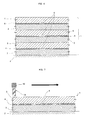
- FIG. 2(a) shows that information is recorded on the read label 1 as an information recording medium by radiating a laser beam 7 in the shape of predetermined characters, bar codes, and the like from the side of the light-transmissive protective film layer 5.
- information is recorded by radiating the laser beam 7 from the side of the transparent protective film layer 5 in a state where the read label 1 as an information recording medium is attached onto the base plate 2 of the equipment via the adhesive layer 3.
- a laser beam having a second harmonic wavelength of 532 nm or a YAG laser beam having a wavelength of 1064 nm can be used for the laser beam 7.
- the laser device may be YV04 laser (MD-V9600 Series/ wavelength : 1064 nm/ average power : 8 W) manufactured by Keyence Corporation.
- the processing can be performed with irradiation parameters set as follows: laser output : 60% to 80%; Q-switching frequency : 1000 KHz; and scanning speed : 2000 mm/sec to 2200 mm/sec.
- the laser device for the second harmonic wavelength of 532 nm may be SHG laser (LP-G Series) manufactured by Panasonic Electric Works SUNX Co., Ltd.
- Irradiation conditions vary depending on the width and accuracy of removal, and thus are not necessarily limited to those as described above.
- the information recording portion 6 can be formed of only the evaporated and removed portion or of the evaporated and removed portion and the metal film layer 4 adjacent thereto by evaporating only a predetermined portion of the metal film layer 4 through the processing under such irradiation conditions as described above.
- information may be recorded by forming characters and/or codes as data in the evaporated and removed portion, that is, the information recording portion 6.
- information may be recorded by forming a barcode in the evaporated and removed portion, that is, the information recording portion 6 and the metal film layer 4 adjacent thereto.
- the base plate 2 may be made of an acrylic resin material
- the metal film layer 4 may be an aluminum vapor-deposited film
- the protective film layer 5 may be made of light-transmissive wax resin.
- the radiated laser beam 7 can pass through the light-transmissive protective film layer 5 to process and evaporate the metal film layer 4 composed of the aluminum vapor-deposited film, so that the predetermined information recording portion 6 can be formed.
- the light-transmissive protective film layer 5 made of the resin material allows the passage of the laser beam 7 having the wavelength of the present embodiment, enabling the metal film layer 4 formed by vapor-deposition or sputtering to evaporate by means of absorption of the laser beam 7.
- the protective film layer 5 may have such light transmittance that a laser beam can pass through the protective film layer 5 to evaporate the metal film layer 4. In the case where the presence or absence of the metal film layer 4 is determined by detection of reflected waves, such light transmission characteristics of the protective film layer 5 as to allow the passage of a large amount of visible light are not required as long as the laser beam 7 can be passed through the protective film layer 5.
- the metal film layer 4 can absorb a laser beam 7 having the wavelength of the present embodiment.
- power from the laser beam 7 is absorbed by the metal film layer 4 to heat a portion of the metal film layer 4 where the power is absorbed.
- the heated metal film layer 4 is gasified and evaporated, and only the predetermined portion of the metal film layer 4 irradiated with the laser beam 7 is removed, so that the information recording portion 6 can be formed.
- Such heat processing involves: focusing and concentrating the laser beam 7 on a predetermined point through a lens disposed in the laser device; intensively targeting at a workpiece only within the diameter of the focal spot to gasify the workpiece with heat; and trimming off and removing the predetermined point.
- the spot diameter is about 50 ⁇ m
- the predetermined point is trimmed off by scanning the laser beam 7 along the content and width of the predetermined point to be formed.
- the predetermined line width of the barcode can be achieved by scanning the laser beam 7 along the predetermined line width multiple times.
- the metal film layer 4 is an aluminum vapor-deposited film.
- the metal film layer 4 may be made of other materials such as palladium, copper, nickel, silver, gold, and iron which have a high absorption rate of laser light and can be typically vapor-deposited and sputtered to form a thin film.
- the above-described materials have absorption rates of laser light of 5% to 10% or more with respect to the laser wavelength of the present embodiment.
- the absorption rates of laser light tend to increase at wavelengths of 532 nm to 1064 nm in which the materials can be subjected to processing by the laser beam 7.
- the second harmonic wavelength of 532 nm and the YAG laser wavelength of 1064 nm are used.
- semiconductor laser with a wavelength of 532 nm to 1064 nm may be used in view of the above-described relation between the absorption rate of laser light in the material characteristics and the wavelength of a laser beam.
- the processing is enabled using laser sources such as fiber laser and YV04 laser capable of outputting the same wavelength as the YAG laser wavelength of 1064 nm.
- the laser beam 7 passes through the protective film layer 5 to remove only the metal film layer 4, thereby preventing metal work pieces from being scattered. Further, since the predetermined portion of the metal film layer 4 is irradiated with the laser beam 7 to perform laser scanning at high speed, the layers above and below the metal film layer 4 and the metal film layer 4 excluding the predetermined portion are hardly affected. Thus, a desired portion of the metal film layer 4 can be removed for formation with high efficiency and accuracy. Since the metal film layer 4 to be removed by laser processing is reduced in thickness to be considerably smaller than the whole layers forming the film, the protective film layer 5 and the like are neither affected nor deformed. The protective film layer 5 allows the passage of the laser beam 7, and is thus neither removed nor deformed directly. This enables the metal film layer 4 to be removed in a closed state in which the metal film layer 4 is held between the protective film layer 5, the adhesive layer 3, and the base plate 2.
- the read label 1 as an information recording medium of the present embodiment includes the adhesive layer 3, the metal film layer 4, and the protective film layer 5.
- the adhesive layer 3 is made thicker than the metal film layer 4, so that a desired information recording portion 6 can be formed by evaporating and removing the metal film layer 4 with the laser beam 7.
- a read label showing a clear contrast can be provided.
- FIG. 4 is a cross-sectional view of a foil printing film according to a second embodiment of the present invention.
- FIG. 5 is cross-sectional views illustrating manufacture of a read label as an information recording medium from a foil printing film according to the second embodiment of the present invention.
- the second embodiment describes a read label as an information recording medium manufactured by thermally transferring information to be recorded onto a label, and a method for recording the information.
- the label includes an adhesive layer, a metal film layer, and a protective film layer which are stacked on a base plate.
- a foil printing film including a base film disposed on a label serving as information is attached to the base plate, and the foil printing film is partly peeled off, so that the information is recorded on the base plate according to the presence or absence of the label.
- the read label as an information recording medium of the present embodiment is manufactured by removing a foil printing film including a label 21 and a base film 8 while leaving parts of the label 21.
- the label 21 includes an adhesive layer 3, a metal film layer 4, and a protective film layer 5 stacked on top of each other.
- the foil printing film includes a PET film disposed as the base film 8 on the label 21 including the adhesive layer 3, the metal film layer 4, and the protective film layer 5 stacked on top of each other.
- a mold release layer (not shown) is applied on a surface of the base film 8 which is in contact with the protective film layer 5. This facilitates the removal of the base film 8 by thermal transfer, which will be described below, from the label 21 to be left as the read label as an information recording medium.
- the metal film layer 4 is separately formed by vapor deposition and the adhesive layer 3 is applied thereon.
- the type of adhesive for the adhesive layer 3 is changed according to the material of a base plate 2, that is, a workpiece onto which the read label as an information recording medium is thermally transferred.
- the base plate 2 may be made of a transparent acrylic material.
- the used base plate 2 is cylindrically-shaped. However, the base plate 2 is shown substantially linearly in an enlarged view of FIG. 5 .
- the foil printing film composed of four layers including the adhesive layer 3, the metal film layer 4, the light-transmissive protective film layer 5, and the base film 8 is disposed on the base plate 2.
- the foil printing film is pressed by a heated roll member 15 to a predetermined portion of the base plate 2 from the side of the base film 8 which is the top layer of four layers of the foil printing film.
- the used heated roll member 15 is made of fluorine-based rubber having hardness of 80 degrees, and the foil printing film is transferred under moderate pressure. At this point, the roll member 15 is pushed to a portion of the label 21 to be left as recorded information.
- the label 21 composed of three layers including the adhesive layer 3, the metal film layer 4, and the light-transmissive protective film layer 5 is separated from the base film 8, so that the film having a three-layered structure, that is, the label 21 composed of three layers including the adhesive layer 3, the metal film layer 4, and the light-transmissive protective film layer 5 is transferred from the base film 8 onto the base plate 2.
- a read label 1 as an information recording medium is formed.
- the read label 1 as an information recording medium can be easily manufactured thus using the foil printing film, the read label 1 as an information recording medium can be formed in an intricately-shaped product including the curved base plate 2 or a part of the product. Further, the read label 1 as an information recording medium is configured according to the presence or absence of the label 21 containing the metal film layer 4, thereby increasing the contrast of the read label to enhance the reliability of reading similarly to the first embodiment.
- each of the layers may have any thickness.
- the film can be transferred onto the curved surface of the base plate 2 being turned by the heated roll member 15 set at 180°C to 200°C.
- the foil printer used in the present embodiment may be, for example, a foil printer manufactured by Navitas Co., Ltd., and the foil printing film may be a film manufactured by Murata-Kimpaku Co., Ltd. Specific examples of dimensions of the layers are provided as follows: the base film 8 is about 16 ⁇ m; the mold release layer as the protective film layer 5 is 1 ⁇ m to 1.5 ⁇ m; the aluminum vapor-deposited layer as the metal film layer 4 is 500 ⁇ (0.05 ⁇ m); and the adhesive layer 3 is 2 ⁇ m to 3 ⁇ m.
- FIG. 6 shows read labels as an information recording medium in multiple layers according to a third embodiment of the present invention, the read labels being obtained by stacking the read labels 1 as an information recording medium according to the first embodiment in multiple layers.
- films each including a light-transmissive protective film layer 5, a metal film layer 4, and an adhesive layer 3 are transferred and printed onto a base plate 2 multiple times to form multiple layers each including the light-transmissive protective film 5, the metal film layer 4, and the adhesive layer 3. Thereafter, the multiple layers are irradiated with a laser beam 7 to form information recording portions 6.
- the films are thermally transferred multiple times in the same position.
- the presence of the adhesive layer 3 enables the films to be thermally transferred any number of times, thereby achieving stacked layers.
- the films each including the information recording portion 6 formed in the metal film layer 4 are stacked in multiple layers.
- the protective film layer 5 or the metal film layer 4 of the read label 1 as an information recording medium is melted due to corrosion caused by cleaning or immersion in a cleaning liquid such as alcohol, the upper read label 1 for an information recording medium can be removed to leave the lower read label 1 for an information recording medium for achieving the object and feature of a read label.
- the upper read label 1 as an information recording medium can be removed to leave the lower read label 1 as an information recording medium for achieving the object and feature of a read label.
- a highly durable read label can be obtained by stacking the read labels 1 as an information recording medium in multiple layers.
- FIG. 7 is a cross-sectional view illustrating a method for reading a read label for an information recording medium according to a fourth embodiment of the present invention.
- FIG. 8(a) is a planar view of a bar code formed on the read label as an information recording medium according to the fourth embodiment of the present invention
- FIG. 8(b) is a cross-sectional view.
- FIG. 9 is a perspective view of the bar code formed on the read label as an information recording medium according to the fourth embodiment of the present invention.
- a read label 1 as an information recording medium or a reader 12 is moved to recognize the content of the read label 1 as an information recording medium by the reader 12.
- the accuracy of reading is determined according to the light and shade or the contrast of an information recording portion 6 in the read label 1 as an information recording medium.
- the durability of the information recording portion 6 is a factor that causes a detection error or false operation. Thus, the durability of the information recording portion 6 is quite important for achieving reading.
- the metal film layer 4 is a thin film formed by vapor-deposition or sputtering so as to have a metal surface.
- the reflectivity of the laser beam is quite high, so that reflected signals can be obtained with high probability.
- a signal difference between the reflected signal and an unreflected signal is extremely large to increase the contrast, thereby achieving highly favorable results of reading with high probability.
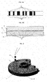
- FIG. 8 shows the information recording portion 6 formed of the barcode.
- Acrylic resin as a base plate 2 is disposed behind a transmission-side barcode 9 for performing reading and a metal film layer 4 is disposed as a reflection-side barcode 10, resulting in a bar code with an increased and clear contrast.
- FIG. 9 shows that the read label 1 as an information recording medium can be applied to the base plate 2 having a curved outer peripheral surface such as a medical biosensor for a blood test and the like.
- the surface of the read label 1 as an information recording medium is protected by a protective film layer 5 even if blood 16 and the like adhere to the surface, and information can be read because the contrast of markings is clear even when the protective film layer 5 is stained with the blood 16.
- the types and manufacturing information of the biosensor can be read without false recognition, so that highly reliable measurement of blood and the like can be achieved.
- the present invention provides resistance to stains on a transparent protective film layer, thereby increasing the reliability of reading by a reader.
- the present invention is applicable to various equipment.
Landscapes
- Physics & Mathematics (AREA)
- General Physics & Mathematics (AREA)
- Engineering & Computer Science (AREA)
- Theoretical Computer Science (AREA)
- Thermal Transfer Or Thermal Recording In General (AREA)
- Laser Beam Processing (AREA)
- Optical Record Carriers And Manufacture Thereof (AREA)
Abstract
Description
- The present invention relates to a read label used as an information recording medium attached to various base materials and a method for recording information thereon.
-
FIG. 10 is cross-sectional views of conventional read labels used as an information recording medium. As shown in FIG. 10 (a), the read label used as an information recording medium includes: anadhesive layer 3a disposed on abase material 2a; apigment layer 17a disposed on theadhesive layer 3a; alaser marking layer 18a disposed on thepigment layer 17a, and aprotective film layer 5a disposed on thelaser marking layer 18a. - In FIG. 10(b), a color-developed
layer 19a is formed by radiating alaser beam 7a onto thelaser marking layer 18a from a laser device such as carbon dioxide laser or YAG laser. - At this point, a desired marking position of the
laser marking layer 18a is irradiated with thelaser beam 7a from the laser device to generate a color only in the desired portion, thereby forming the color-developedlayer 19a. Thelaser beam 7a to be used depends on the material of thelaser marking layer 18a. Information is read by distinguishing or identifying the desired marking from a color difference between the color-developedlayer 19a and thepigment layer 17a disposed under thelaser marking layer 18a (similar techniques are disclosed by, for example,Patent Literatures -
- Patent Literature 1: Japanese Utility Model Registration No.
3148390 - Patent Literature 2: Japanese Unexamined Patent Application Publication No.
2007-313876 - In the above-described conventional configuration of the read label used as an information recording medium on which reading is performed by a reader, for example, a bar code or the like with information recorded thereon is hardly identified from a contrast between the stained
protective film layer 5a and the color-developedlayer 19a, thereby resulting in a factor that causes a false operation or detection error of the reader. In other words, in the case of adhesion of dirt, the contrast is not made clear only by a color difference, thereby reducing the reliability of reading. Hence, an object of the present invention is to improve the reliability of reading. - In order to attain the object, a read label used as an information recording medium of the present invention comprises: an adhesive layer; a metal film layer disposed on the surface of the adhesive layer; and a light-transmissive protective film layer disposed on the surface of the metal film layer, wherein the adhesive layer and the light-transmissive protective film layer are larger in thickness than the metal film layer, and an evaporated and removed portion is provided in a part of the metal film layer. Thus, the desired object is attained.
- Further, a method for recording information on the read label used as an information recording medium of the present invention comprises radiating a laser beam on the metal film layer from the side of the light-transmissive protective film layer to evaporate and remove a part of the metal film layer and thus form an evaporated and removed portion. Thus, the desired object is attained.
-
- [
FIG. 1] FIG. 1 is a cross-sectional view of a read label used as an information recording medium according to a first embodiment of the present invention. - [
FIG. 2] FIG. 2 is cross-sectional views illustrating laser processing in a manufacturing process of the read label used as an information recording medium according to the first embodiment of the present invention. - [
FIG. 3] FIG. 3 is another cross-sectional view of the read label used as an information recording medium according to the first embodiment of the present invention. - [
FIG. 4] FIG. 4 is a cross-sectional view of a foil printing film according to a second embodiment of the present invention. - [
FIG. 5] FIG. 5 is cross-sectional views illustrating manufacture of a read label used as an information recording medium from a foil printing film according to the second embodiment of the present invention. - [
FIG. 6] FIG. 6 is a cross-sectional view of read labels used as an information recording medium in multiple layers according to a third embodiment of the present invention. - [
FIG. 7] FIG. 7 is a cross-sectional view illustrating a method for reading a read label used as an information recording medium according to a fourth embodiment of the present invention. - [
FIG. 8] FIG. 8 shows that a bar code is formed in the read label used as an information recording medium according to the fourth embodiment of the present invention. - [
FIG. 9] FIG. 9 is a perspective view showing that the bar code is formed on the read label used as an information recording medium according to the fourth embodiment of the present invention. - [
FIG. 10] FIG. 10 is cross-sectional views of conventional read labels used as an information recording medium. - The following will specifically describe a read label used as an information recording medium according to the present invention in reference to the accompanying drawings.
-
FIG. 1 is a cross-sectional view of a read label used as an information recording medium according to a first embodiment of the present invention.FIG. 2 is cross-sectional views illustrating laser processing in a manufacturing process of the read label used as an information recording medium according to the first embodiment of the present invention.FIG. 3 is another cross-sectional view of the read label used as an information recording medium according to the first embodiment of the present invention. - A range of equipment and articles including testing samples and physically distributed and commercial products contain information such as the contents and histories. Such information is written on read labels, the read labels are attached to the equipment and articles, and the information recorded on the read labels is read and managed as necessary. The present invention relates to the read label used as an information recording medium where the information is recorded and a method for recording the information. The following will describe the read label used as an information recording medium and the method for recording the information, the read label being attached to a base plate, that is, a surface of the equipment or article or of a container in which the equipment or article is housed.
- In
FIG. 1 , aread label 1 used as an information recording medium is composed of anadhesive layer 3 attached onto abase plate 2 of the equipment, ametal film layer 4 disposed on the surface of theadhesive layer 3, and a light-transmissiveprotective film layer 5 disposed on the surface of themetal film layer 4. - A feature of the present embodiment is that an
information recording portion 6 is formed by causing themetal film layer 4 to evaporate without having the effect of processing on theprotective film layer 5 and thebase plate 2 to which the label as an information recording medium is attached. - As described above, the
metal film layer 4 is formed on theadhesive layer 3 which is sufficiently thicker than, for example, at least ten times as thick as themetal film layer 4, and theinformation recording portion 6 containing nometal film layer 4 is formed in themetal film layer 4. Thus, there is a clearer contrast between the presence and absence of themetal film layer 4 than between different colors, so that reading is facilitated. As a result, for example, identification errors can be prevented when the label is read by a reader even if the transparent protective film layer is stained, so that the reliability of reading by the reader can be enhanced. - Further, unlike in the related art, it is not necessary to form complex multiple layers including a protective film layer, a laser marking layer, a pigment layer, and an adhesive layer, thereby facilitating manufacturing and reducing cost.
- In the above-described evaporation, a quantity of heat is concentrated by laser light irradiation on a small area of the target
metal film layer 4, which is considerably thinner than theprotective film layer 5 and theadhesive layer 3, to increase energy density, so that the area of the metallayer film layer 4 is vaporized. - Further, the
adhesive layer 3 is sufficiently thicker than themetal film layer 4, so that the vaporized and gasifiedmetal film layer 4 can be contained in theadhesive layer 3. Specifically, in the laser light irradiation, a laser beam passes through the light-transmissiveprotective film layer 5, vaporizes themetal film layer 4, and softens theadhesive layer 3, so that the vaporized and gasifiedmetal film layer 4 can be contained in the softened portion of theadhesive layer 3. - The reason why the
adhesive layer 3 is softened will be more specifically described. Theadhesive layer 3 may be also light transmissive. However, the surface of theadhesive layer 3 on the side of themetal film layer 4 is subjected to heat and pressure by a heatedroll member 15 in the step ofFIG. 5 which will be described later, and thus becomes rough (uneven), thereby allowing a radiated laser beam to be absorbed in theadhesive layer 3 without passing through. In addition, theadhesive layer 3 is softened due to heat supplied during the evaporation of themetal film layer 4. - Moreover, the
adhesive layer 3 is softened, so that a containing portion (no reference numeral assigned) which contains the evaporatedmetal film layer 4 is formed. The containing portion is formed in the softened portion of theadhesive layer 3 which is in contact with the lower part of the evaporated and removed portion of themetal film layer 4. Further, since a laser beam does not pass through the adhesive layer, thebase plate 2 is not affected by a laser beam. - Accordingly, the vaporized and gasified
metal film layer 4 is contained in theadhesive layer 3, and thus the gasifiedmetal film layer 4 is prevented from affecting theinformation recording portion 6 and theprotective film layer 5 without being contained anywhere. Hence, information can be accurately recorded. -
FIG. 2(a) shows that information is recorded on theread label 1 as an information recording medium by radiating alaser beam 7 in the shape of predetermined characters, bar codes, and the like from the side of the light-transmissiveprotective film layer 5. - That is, information is recorded by radiating the
laser beam 7 from the side of the transparentprotective film layer 5 in a state where theread label 1 as an information recording medium is attached onto thebase plate 2 of the equipment via theadhesive layer 3. - In the present embodiment, a laser beam having a second harmonic wavelength of 532 nm or a YAG laser beam having a wavelength of 1064 nm can be used for the
laser beam 7. - For example, the laser device may be YV04 laser (MD-V9600 Series/ wavelength : 1064 nm/ average power : 8 W) manufactured by Keyence Corporation. The processing can be performed with irradiation parameters set as follows: laser output : 60% to 80%; Q-switching frequency : 1000 KHz; and scanning speed : 2000 mm/sec to 2200 mm/sec. Further, the laser device for the second harmonic wavelength of 532 nm may be SHG laser (LP-G Series) manufactured by Panasonic Electric Works SUNX Co., Ltd.
- Irradiation conditions vary depending on the width and accuracy of removal, and thus are not necessarily limited to those as described above.
- In
FIG. 2(b) , theinformation recording portion 6 can be formed of only the evaporated and removed portion or of the evaporated and removed portion and themetal film layer 4 adjacent thereto by evaporating only a predetermined portion of themetal film layer 4 through the processing under such irradiation conditions as described above. In other words, information may be recorded by forming characters and/or codes as data in the evaporated and removed portion, that is, theinformation recording portion 6. Alternatively, information may be recorded by forming a barcode in the evaporated and removed portion, that is, theinformation recording portion 6 and themetal film layer 4 adjacent thereto. - Under the above-described conditions of the present embodiment, the
base plate 2 may be made of an acrylic resin material, themetal film layer 4 may be an aluminum vapor-deposited film, and theprotective film layer 5 may be made of light-transmissive wax resin. - With this configuration, the radiated
laser beam 7 can pass through the light-transmissiveprotective film layer 5 to process and evaporate themetal film layer 4 composed of the aluminum vapor-deposited film, so that the predeterminedinformation recording portion 6 can be formed. - This is because, based on the relation between the absorption rate of laser light of the material and the wavelength of laser light, the light-transmissive
protective film layer 5 made of the resin material allows the passage of thelaser beam 7 having the wavelength of the present embodiment, enabling themetal film layer 4 formed by vapor-deposition or sputtering to evaporate by means of absorption of thelaser beam 7. Theprotective film layer 5 may have such light transmittance that a laser beam can pass through theprotective film layer 5 to evaporate themetal film layer 4. In the case where the presence or absence of themetal film layer 4 is determined by detection of reflected waves, such light transmission characteristics of theprotective film layer 5 as to allow the passage of a large amount of visible light are not required as long as thelaser beam 7 can be passed through theprotective film layer 5. - The processing will be specifically described below. As described above, the
metal film layer 4 can absorb alaser beam 7 having the wavelength of the present embodiment. Thus, power from thelaser beam 7 is absorbed by themetal film layer 4 to heat a portion of themetal film layer 4 where the power is absorbed. The heatedmetal film layer 4 is gasified and evaporated, and only the predetermined portion of themetal film layer 4 irradiated with thelaser beam 7 is removed, so that theinformation recording portion 6 can be formed. - Such heat processing involves: focusing and concentrating the
laser beam 7 on a predetermined point through a lens disposed in the laser device; intensively targeting at a workpiece only within the diameter of the focal spot to gasify the workpiece with heat; and trimming off and removing the predetermined point. - In the case of the
laser beam 7 of the present embodiment, the spot diameter is about 50 µm, and the predetermined point is trimmed off by scanning thelaser beam 7 along the content and width of the predetermined point to be formed. For example, in the case where a line forming a barcode is removed, the predetermined line width of the barcode can be achieved by scanning thelaser beam 7 along the predetermined line width multiple times. - In the present embodiment, the
metal film layer 4 is an aluminum vapor-deposited film. However, themetal film layer 4 may be made of other materials such as palladium, copper, nickel, silver, gold, and iron which have a high absorption rate of laser light and can be typically vapor-deposited and sputtered to form a thin film. - The above-described materials have absorption rates of laser light of 5% to 10% or more with respect to the laser wavelength of the present embodiment. In the characteristics of the materials, the absorption rates of laser light tend to increase at wavelengths of 532 nm to 1064 nm in which the materials can be subjected to processing by the
laser beam 7. - Further, in the present embodiment, the second harmonic wavelength of 532 nm and the YAG laser wavelength of 1064 nm are used. However, semiconductor laser with a wavelength of 532 nm to 1064 nm may be used in view of the above-described relation between the absorption rate of laser light in the material characteristics and the wavelength of a laser beam. Moreover, the processing is enabled using laser sources such as fiber laser and YV04 laser capable of outputting the same wavelength as the YAG laser wavelength of 1064 nm.
- When the same processing was performed using CO2 laser with a wavelength of 10.6 µm or 9.3 µm for the
laser beam 7, since the resin material of theprotective film layer 5 has a high absorption rate of laser light having the wavelength, theprotective film layer 5 underwent processing and thus became uneven as shown inFIG. 2(c) . Thus, disadvantageously, the processing and reading of theinformation recording portion 6 could not be performed with high accuracy. - In the laser processing of the present embodiment, the
laser beam 7 passes through theprotective film layer 5 to remove only themetal film layer 4, thereby preventing metal work pieces from being scattered. Further, since the predetermined portion of themetal film layer 4 is irradiated with thelaser beam 7 to perform laser scanning at high speed, the layers above and below themetal film layer 4 and themetal film layer 4 excluding the predetermined portion are hardly affected. Thus, a desired portion of themetal film layer 4 can be removed for formation with high efficiency and accuracy. Since themetal film layer 4 to be removed by laser processing is reduced in thickness to be considerably smaller than the whole layers forming the film, theprotective film layer 5 and the like are neither affected nor deformed. Theprotective film layer 5 allows the passage of thelaser beam 7, and is thus neither removed nor deformed directly. This enables themetal film layer 4 to be removed in a closed state in which themetal film layer 4 is held between theprotective film layer 5, theadhesive layer 3, and thebase plate 2. - In
FIG. 3 , even if the portion to be evaporated by thelaser beam 7 contains theadhesive layer 3, the portion is originally the evaporated portion of themetal film layer 4 and thus does not affect reading. - As described above, the
read label 1 as an information recording medium of the present embodiment includes theadhesive layer 3, themetal film layer 4, and theprotective film layer 5. Theadhesive layer 3 is made thicker than themetal film layer 4, so that a desiredinformation recording portion 6 can be formed by evaporating and removing themetal film layer 4 with thelaser beam 7. Thus, a read label showing a clear contrast can be provided. -
FIG. 4 is a cross-sectional view of a foil printing film according to a second embodiment of the present invention.FIG. 5 is cross-sectional views illustrating manufacture of a read label as an information recording medium from a foil printing film according to the second embodiment of the present invention. - The second embodiment describes a read label as an information recording medium manufactured by thermally transferring information to be recorded onto a label, and a method for recording the information. The label includes an adhesive layer, a metal film layer, and a protective film layer which are stacked on a base plate. In the read label as an information recording medium of the second embodiment, a foil printing film including a base film disposed on a label serving as information is attached to the base plate, and the foil printing film is partly peeled off, so that the information is recorded on the base plate according to the presence or absence of the label.
- As shown in
FIG. 4 , the read label as an information recording medium of the present embodiment is manufactured by removing a foil printing film including alabel 21 and abase film 8 while leaving parts of thelabel 21. Thelabel 21 includes anadhesive layer 3, ametal film layer 4, and aprotective film layer 5 stacked on top of each other. For example, the foil printing film includes a PET film disposed as thebase film 8 on thelabel 21 including theadhesive layer 3, themetal film layer 4, and theprotective film layer 5 stacked on top of each other. - In recording information, first, a mold release layer (not shown) is applied on a surface of the
base film 8 which is in contact with theprotective film layer 5. This facilitates the removal of thebase film 8 by thermal transfer, which will be described below, from thelabel 21 to be left as the read label as an information recording medium. - In this case, the
metal film layer 4 is separately formed by vapor deposition and theadhesive layer 3 is applied thereon. The type of adhesive for theadhesive layer 3 is changed according to the material of abase plate 2, that is, a workpiece onto which the read label as an information recording medium is thermally transferred. For example, thebase plate 2 may be made of a transparent acrylic material. - A further description will be given in reference to
FIG. 5 . - In the following description, the used
base plate 2 is cylindrically-shaped. However, thebase plate 2 is shown substantially linearly in an enlarged view ofFIG. 5 . - First, in
FIG. 5(a) , the foil printing film composed of four layers including theadhesive layer 3, themetal film layer 4, the light-transmissiveprotective film layer 5, and thebase film 8 is disposed on thebase plate 2. - Next, in
FIG 5(b) , the foil printing film is pressed by aheated roll member 15 to a predetermined portion of thebase plate 2 from the side of thebase film 8 which is the top layer of four layers of the foil printing film. In the present embodiment, the usedheated roll member 15 is made of fluorine-based rubber having hardness of 80 degrees, and the foil printing film is transferred under moderate pressure. At this point, theroll member 15 is pushed to a portion of thelabel 21 to be left as recorded information. - Accordingly, in
FIG. 5(c) , thelabel 21 composed of three layers including theadhesive layer 3, themetal film layer 4, and the light-transmissiveprotective film layer 5 is separated from thebase film 8, so that the film having a three-layered structure, that is, thelabel 21 composed of three layers including theadhesive layer 3, themetal film layer 4, and the light-transmissiveprotective film layer 5 is transferred from thebase film 8 onto thebase plate 2. Thus, aread label 1 as an information recording medium is formed. - Since the
read label 1 as an information recording medium can be easily manufactured thus using the foil printing film, theread label 1 as an information recording medium can be formed in an intricately-shaped product including thecurved base plate 2 or a part of the product. Further, theread label 1 as an information recording medium is configured according to the presence or absence of thelabel 21 containing themetal film layer 4, thereby increasing the contrast of the read label to enhance the reliability of reading similarly to the first embodiment. In the present embodiment, each of the layers may have any thickness. - In the present embodiment, the film can be transferred onto the curved surface of the
base plate 2 being turned by theheated roll member 15 set at 180°C to 200°C. The foil printer used in the present embodiment may be, for example, a foil printer manufactured by Navitas Co., Ltd., and the foil printing film may be a film manufactured by Murata-Kimpaku Co., Ltd. Specific examples of dimensions of the layers are provided as follows: thebase film 8 is about 16 µm; the mold release layer as theprotective film layer 5 is 1 µm to 1.5 µm; the aluminum vapor-deposited layer as themetal film layer 4 is 500Å (0.05 µm); and theadhesive layer 3 is 2 µm to 3 µm. -
FIG. 6 shows read labels as an information recording medium in multiple layers according to a third embodiment of the present invention, the read labels being obtained by stacking the read labels 1 as an information recording medium according to the first embodiment in multiple layers. - In
FIG. 6 , for example, films each including a light-transmissiveprotective film layer 5, ametal film layer 4, and anadhesive layer 3 are transferred and printed onto abase plate 2 multiple times to form multiple layers each including the light-transmissiveprotective film 5, themetal film layer 4, and theadhesive layer 3. Thereafter, the multiple layers are irradiated with alaser beam 7 to forminformation recording portions 6. - In the present embodiment, the films are thermally transferred multiple times in the same position. The presence of the
adhesive layer 3 enables the films to be thermally transferred any number of times, thereby achieving stacked layers. - As described above, the films each including the
information recording portion 6 formed in themetal film layer 4 are stacked in multiple layers. Thus, even if theprotective film layer 5 or themetal film layer 4 of the readlabel 1 as an information recording medium is melted due to corrosion caused by cleaning or immersion in a cleaning liquid such as alcohol, theupper read label 1 for an information recording medium can be removed to leave thelower read label 1 for an information recording medium for achieving the object and feature of a read label. - Also in the case where reading cannot be performed due to peeling off during carriage of the base plate, the
upper read label 1 as an information recording medium can be removed to leave thelower read label 1 as an information recording medium for achieving the object and feature of a read label. Thus, a highly durable read label can be obtained by stacking the read labels 1 as an information recording medium in multiple layers. -
FIG. 7 is a cross-sectional view illustrating a method for reading a read label for an information recording medium according to a fourth embodiment of the present invention.FIG. 8(a) is a planar view of a bar code formed on the read label as an information recording medium according to the fourth embodiment of the present invention, andFIG. 8(b) is a cross-sectional view.FIG. 9 is a perspective view of the bar code formed on the read label as an information recording medium according to the fourth embodiment of the present invention. - In
FIG. 7 , aread label 1 as an information recording medium or areader 12 is moved to recognize the content of the readlabel 1 as an information recording medium by thereader 12. In reading, the accuracy of reading is determined according to the light and shade or the contrast of aninformation recording portion 6 in theread label 1 as an information recording medium. The durability of theinformation recording portion 6 is a factor that causes a detection error or false operation. Thus, the durability of theinformation recording portion 6 is quite important for achieving reading. - In each of the read labels 1 as an information recording medium according to the embodiments of the present invention, the
metal film layer 4 is a thin film formed by vapor-deposition or sputtering so as to have a metal surface. Thus, when aread laser beam 14 is used as reading means, the reflectivity of the laser beam is quite high, so that reflected signals can be obtained with high probability. In other words, a signal difference between the reflected signal and an unreflected signal is extremely large to increase the contrast, thereby achieving highly favorable results of reading with high probability. -
FIG. 8 shows theinformation recording portion 6 formed of the barcode. Acrylic resin as abase plate 2 is disposed behind a transmission-side barcode 9 for performing reading and ametal film layer 4 is disposed as a reflection-side barcode 10, resulting in a bar code with an increased and clear contrast. -
FIG. 9 shows that theread label 1 as an information recording medium can be applied to thebase plate 2 having a curved outer peripheral surface such as a medical biosensor for a blood test and the like. - In this case, the surface of the read
label 1 as an information recording medium is protected by aprotective film layer 5 even ifblood 16 and the like adhere to the surface, and information can be read because the contrast of markings is clear even when theprotective film layer 5 is stained with theblood 16. Thus, the types and manufacturing information of the biosensor can be read without false recognition, so that highly reliable measurement of blood and the like can be achieved. - As described above, in the present invention, information is recorded by evaporating and removing a metal film layer, thereby providing a clearer contrast than information recording using a color difference. As a result, for example, the present invention provides resistance to stains on a transparent protective film layer, thereby increasing the reliability of reading by a reader.
- Therefore, the present invention is applicable to various equipment.
Claims (11)
- A read label used as an information recording medium comprising:an adhesive layer;a metal film layer disposed on a surface of the adhesive layer; anda light-transmissive protective film layer disposed on a surface of the metal film layer, whereinthe adhesive layer and the light-transmissive protective film layer are larger in thickness than the metal film layer, andan evaporated and removed portion is provided in a part of the metal film layer.
- The read label used as an information recording medium according to claim 1, wherein an information recording portion is formed of the evaporated and removed portion and a portion of the metal film layer adjacent to the evaporated and removed portion.
- The read label used as an information recording medium according to claim 1 or 2, wherein the adhesive layer and the light-transmissive protective film layer are at least ten times as thick as the metal film layer.
- The read label used as an information recording medium according to any one of claims 1 to 3, wherein a containing portion for containing the evaporated metal film layer is formed in a portion of the adhesive layer which is in contact with the evaporated and removed portion of the metal film layer.
- The read label used as an information recording medium according to any one of claims 1 to 4, wherein the metal film layer is made of at least one of aluminum, palladium, copper, nickel, silver, gold, and iron.
- The read label used as an information recording medium according to any one of claims 1 to 5, wherein the metal film layer is formed on the surface of the adhesive layer by vapor-deposition or sputtering.
- A read label used as an information recording medium comprising the read labels used as an information recording medium according to any one of claims 1 to 6 stacked in multiple layers.
- A method for recording information on a read label used as an information recording medium comprising an adhesive layer, a metal film layer disposed on a surface of the adhesive layer, and a light-transmissive protective film layer disposed on a surface of the metal film layer, wherein the adhesive layer and the light-transmissive protective film layer are larger in thickness than the metal film layer, and an evaporated and removed portion is provided in the metal film layer,
the method comprising radiating a laser beam on the metal film layer from a side of the light-transmissive protective film layer to evaporate and remove a part of the metal film layer and thus form an evaporated and removed portion. - The method for recording information on the read label used as an information recording medium according to claim 8, wherein the laser beam has a YAG laser wavelength or a second harmonic wavelength.
- The method for recording information on the read label used as an information recording medium according to claim 8 or 9, further comprising forming a rough surface on a portion in the surface of the adhesive layer facing the evaporated and removed portion of the metal film layer before the laser beam is radiated.
- The method for recording information on the read label used as an information recording medium according to any one of claims 8 to 10, further comprising bonding a surface of the adhesive layer opposite to the metal film layer to a base material, before radiating the laser beam from the side of the light-transmissive protective film layer.
Applications Claiming Priority (2)
| Application Number | Priority Date | Filing Date | Title |
|---|---|---|---|
| JP2011095774 | 2011-04-22 | ||
| PCT/JP2012/002377 WO2012144146A1 (en) | 2011-04-22 | 2012-04-05 | Read label for information recording medium and information recording method therefor |
Publications (3)
| Publication Number | Publication Date |
|---|---|
| EP2587470A1 true EP2587470A1 (en) | 2013-05-01 |
| EP2587470A4 EP2587470A4 (en) | 2014-01-22 |
| EP2587470B1 EP2587470B1 (en) | 2016-06-22 |
Family
ID=47041281
Family Applications (1)
| Application Number | Title | Priority Date | Filing Date |
|---|---|---|---|
| EP12773905.0A Active EP2587470B1 (en) | 2011-04-22 | 2012-04-05 | Read label for information recording medium and information recording method therefor |
Country Status (5)
| Country | Link |
|---|---|
| US (1) | US8899485B2 (en) |
| EP (1) | EP2587470B1 (en) |
| JP (2) | JPWO2012144146A1 (en) |
| CN (1) | CN102893314B (en) |
| WO (1) | WO2012144146A1 (en) |
Families Citing this family (8)
| Publication number | Priority date | Publication date | Assignee | Title |
|---|---|---|---|---|
| US9531906B2 (en) * | 2010-06-11 | 2016-12-27 | Xerox Corporation | Method for automatic conversion of paper records to digital form |
| CN103971590B (en) * | 2013-02-01 | 2017-02-22 | 比亚迪股份有限公司 | Anti-counterfeiting trademark and manufacturing method thereof |
| CN106295755A (en) * | 2015-05-27 | 2017-01-04 | 东莞文胜鼎电子科技有限公司 | Two-dimensional code generation method, detection method, detection device and anti-counterfeit label |
| JP6707332B2 (en) * | 2015-10-29 | 2020-06-10 | 株式会社トッパンインフォメディア | Information recording medium |
| CN106448439B (en) * | 2016-10-04 | 2020-12-01 | 勺海数据科技(深圳)有限公司 | Multilayer anti-counterfeiting label, manufacturing method and using method thereof |
| JP6489241B2 (en) * | 2018-01-10 | 2019-03-27 | 大日本印刷株式会社 | Printing method |
| CN110399937B (en) * | 2018-04-17 | 2023-05-26 | 鹏鼎控股(深圳)股份有限公司 | Information detection method for printed circuit board |
| JP2023123133A (en) * | 2022-02-24 | 2023-09-05 | 三菱マテリアル株式会社 | Method for manufacturing insulated circuit board and bonded body for insulated circuit board |
Family Cites Families (29)
| Publication number | Priority date | Publication date | Assignee | Title |
|---|---|---|---|---|
| JPS56105958A (en) * | 1980-01-30 | 1981-08-22 | Sony Corp | Metallic sheet |
| JPS63154280A (en) * | 1986-12-17 | 1988-06-27 | Fuji Electric Corp Res & Dev Ltd | Laser beam machine |
| JP2779234B2 (en) | 1989-11-06 | 1998-07-23 | ヤマハ発動機株式会社 | Fuel tank breather device |
| JPH0497272A (en) * | 1990-08-10 | 1992-03-30 | Toppan Printing Co Ltd | Label |
| JPH04234052A (en) * | 1990-12-28 | 1992-08-21 | Iseto Shiko Kk | Metal evaporated label suitable for printing by nonimpact printer of electrophotographic system |
| DE19642040C1 (en) | 1996-10-11 | 1998-01-15 | Schreiner Etiketten | Label with hologram, written by laser beam passing through clear, protective upper film |
| JPH10142748A (en) * | 1996-11-06 | 1998-05-29 | Fuji Photo Film Co Ltd | Method for sticking label to photographic film cartridge |
| AUPP231598A0 (en) * | 1998-03-13 | 1998-04-09 | Mikoh Technology Limited | A method of recording information ii |
| EP0985207A4 (en) * | 1997-04-03 | 2000-03-15 | Mikoh Corp Limited | Information recording method |
| JPH10333574A (en) * | 1997-05-30 | 1998-12-18 | Toppan Printing Co Ltd | Counterfeit prevention label material and method for manufacturing the same |
| JPH11198537A (en) * | 1998-01-12 | 1999-07-27 | Dainippon Printing Co Ltd | Composite for heat-sensitive destruction pattern formation |
| JP2000019963A (en) * | 1998-06-30 | 2000-01-21 | Lintec Corp | Production of tacky adhesive label laminate |
| JP2001331109A (en) * | 2000-05-23 | 2001-11-30 | Nikou Insatsu Kk | Label book for sticking to refuse bag |
| DE20017501U1 (en) * | 2000-10-12 | 2000-12-14 | Schreiner GmbH & Co. KG, 85764 Oberschleißheim | Foil that can be labeled with a laser beam |
| JP2003150027A (en) * | 2001-11-08 | 2003-05-21 | Sankyo Seiki Mfg Co Ltd | Hologram sheet for metallic vapor deposition type hot printing, and its processing method |
| JP3728542B2 (en) * | 2002-06-13 | 2005-12-21 | 株式会社佐々木印刷 | Laminated label and manufacturing method thereof |
| JP4097128B2 (en) * | 2002-07-01 | 2008-06-11 | 大日本印刷株式会社 | Label for volume hologram laminate production |
| JP4233355B2 (en) | 2003-01-16 | 2009-03-04 | 株式会社資生堂 | LAMINATED MATERIAL MARKED, ARTICLE Attached IT, AND INFORMATION CODE OBSERVATION METHOD |
| CN100461208C (en) * | 2003-01-16 | 2009-02-11 | 株式会社资生堂 | Observation methods for laminated materials with information engraved on them, items pasted with the materials, and information codes |
| JP2005014492A (en) * | 2003-06-27 | 2005-01-20 | Dainippon Printing Co Ltd | Print media |
| JP2005119106A (en) * | 2003-10-16 | 2005-05-12 | Toppan Printing Co Ltd | Article for which anti-counterfeiting measures have been taken and method for manufacturing the same |
| JP2005164788A (en) * | 2003-12-01 | 2005-06-23 | Tokai Aluminum Foil Co Ltd | Resonance label |
| TWI302309B (en) | 2003-12-16 | 2008-10-21 | Victor Company Of Japan | Optical storage medium |
| JP2007313876A (en) | 2006-04-28 | 2007-12-06 | Toyo Ink Mfg Co Ltd | LASER PRINTING METHOD AND PACKAGING OR LABEL HAVING LASER PRINTING OBTAINED BY THE METHOD |
| US8284468B2 (en) | 2006-09-11 | 2012-10-09 | Dai Nippon Printing Co., Ltd. | Authenticating medium and authenticatable substrate |
| JP2009034905A (en) * | 2007-08-01 | 2009-02-19 | Nitto Denko Corp | Laser marking label |
| JP5343403B2 (en) | 2008-05-28 | 2013-11-13 | Dic株式会社 | Adhesive film for laminating and laser marking label |
| JP3148390U (en) | 2008-11-28 | 2009-02-12 | 株式会社村田金箔 | Laser marking foil for printing |
| JP5224060B2 (en) | 2009-04-27 | 2013-07-03 | 大日本印刷株式会社 | Anti-counterfeit media |
-
2012
- 2012-04-05 WO PCT/JP2012/002377 patent/WO2012144146A1/en not_active Ceased
- 2012-04-05 JP JP2012540213A patent/JPWO2012144146A1/en active Pending
- 2012-04-05 EP EP12773905.0A patent/EP2587470B1/en active Active
- 2012-04-05 US US13/703,757 patent/US8899485B2/en active Active
- 2012-04-05 CN CN201280001320.8A patent/CN102893314B/en active Active
-
2015
- 2015-06-08 JP JP2015115365A patent/JP2015172780A/en active Pending
Also Published As
| Publication number | Publication date |
|---|---|
| EP2587470B1 (en) | 2016-06-22 |
| JP2015172780A (en) | 2015-10-01 |
| WO2012144146A1 (en) | 2012-10-26 |
| CN102893314B (en) | 2015-11-25 |
| JPWO2012144146A1 (en) | 2014-07-28 |
| CN102893314A (en) | 2013-01-23 |
| US20130082111A1 (en) | 2013-04-04 |
| US8899485B2 (en) | 2014-12-02 |
| EP2587470A4 (en) | 2014-01-22 |
Similar Documents
| Publication | Publication Date | Title |
|---|---|---|
| EP2587470B1 (en) | Read label for information recording medium and information recording method therefor | |
| JP6938504B2 (en) | Manufacturing method of security element and transfer film | |
| JP2009163713A (en) | Method for producing a smart label that can be recorded with a laser and has adhesive properties | |
| CN110712451B (en) | Optical anti-counterfeiting element and preparation method thereof, and optical anti-counterfeiting product | |
| US20010036537A1 (en) | Method for marking a laminated film material | |
| EP3763173B1 (en) | Method for manufacturing chip-free radiofrequency identification (rfid) devices | |
| US20150367670A1 (en) | Method of using laser ablation to reveal underlying security feature and device obtained thereby | |
| JP2019174323A (en) | Identification tag, interference wave form detecting method, and authenticity evaluation method for the same | |
| US20060180271A1 (en) | Optical recording medium and manufacturing method thereof | |
| CN1942949B (en) | Optical disk and method of producing the same | |
| JP2013071330A (en) | Information card and method for manufacturing the same | |
| EP0985207A1 (en) | Information recording method | |
| CN114536920A (en) | Composite membrane and preparation method and application thereof | |
| JPH0452238B2 (en) | ||
| JP4391334B2 (en) | Authenticity determination medium, authenticity determination medium affixing label, authenticity determination medium transfer sheet, and authenticity determination body | |
| JP2764566B2 (en) | Method for producing optical recording layer transfer sheet | |
| CN118696376A (en) | Ultra-thin data carrier and readout method | |
| AU749161B2 (en) | Method of recording information | |
| JP2005186339A (en) | Thermal recording medium and thermal recording method | |
| JP2017021313A (en) | Hologram display sheet | |
| JPS62164238A (en) | Optical recording medium | |
| GB2407798A (en) | Production of two sided microdots | |
| CN119509588A (en) | Optical scale for encoder, optical scale assembly for encoder, and optical encoder | |
| JP2002157785A (en) | Information recording medium | |
| JPH0793495A (en) | INFORMATION RECORDING MEDIUM, RECORDED INFORMATION READING METHOD AND DEVICE THEREOF |
Legal Events
| Date | Code | Title | Description |
|---|---|---|---|
| PUAI | Public reference made under article 153(3) epc to a published international application that has entered the european phase |
Free format text: ORIGINAL CODE: 0009012 |
|
| 17P | Request for examination filed |
Effective date: 20121228 |
|
| AK | Designated contracting states |
Kind code of ref document: A1 Designated state(s): AL AT BE BG CH CY CZ DE DK EE ES FI FR GB GR HR HU IE IS IT LI LT LU LV MC MK MT NL NO PL PT RO RS SE SI SK SM TR |
|
| A4 | Supplementary search report drawn up and despatched |
Effective date: 20131220 |
|
| RIC1 | Information provided on ipc code assigned before grant |
Ipc: B23K 26/42 20060101ALI20131216BHEP Ipc: G06K 19/06 20060101ALI20131216BHEP Ipc: B41M 5/26 20060101ALI20131216BHEP Ipc: B23K 26/40 20060101ALI20131216BHEP Ipc: B23K 26/36 20060101ALI20131216BHEP Ipc: G09F 3/02 20060101AFI20131216BHEP |
|
| RAP1 | Party data changed (applicant data changed or rights of an application transferred) |
Owner name: PANASONIC HEALTHCARE CO., LTD. |
|
| DAX | Request for extension of the european patent (deleted) | ||
| 17Q | First examination report despatched |
Effective date: 20141120 |
|
| RAP1 | Party data changed (applicant data changed or rights of an application transferred) |
Owner name: PANASONIC HEALTHCARE HOLDINGS CO., LTD. |
|
| GRAP | Despatch of communication of intention to grant a patent |
Free format text: ORIGINAL CODE: EPIDOSNIGR1 |
|
| RIC1 | Information provided on ipc code assigned before grant |
Ipc: B23K 26/40 20140101ALI20151208BHEP Ipc: G09F 3/02 20060101AFI20151208BHEP Ipc: B23K 26/362 20140101ALI20151208BHEP Ipc: G06K 19/06 20060101ALI20151208BHEP |
|
| INTG | Intention to grant announced |
Effective date: 20160104 |
|
| GRAS | Grant fee paid |
Free format text: ORIGINAL CODE: EPIDOSNIGR3 |
|
| GRAA | (expected) grant |
Free format text: ORIGINAL CODE: 0009210 |
|
| RIN1 | Information on inventor provided before grant (corrected) |
Inventor name: KIJIMA, TOMOHIRO Inventor name: SHIGEKAWA, YASUSHI |
|
| AK | Designated contracting states |
Kind code of ref document: B1 Designated state(s): AL AT BE BG CH CY CZ DE DK EE ES FI FR GB GR HR HU IE IS IT LI LT LU LV MC MK MT NL NO PL PT RO RS SE SI SK SM TR |
|
| REG | Reference to a national code |
Ref country code: GB Ref legal event code: FG4D |
|
| REG | Reference to a national code |
Ref country code: CH Ref legal event code: EP |
|
| REG | Reference to a national code |
Ref country code: IE Ref legal event code: FG4D |
|
| REG | Reference to a national code |
Ref country code: AT Ref legal event code: REF Ref document number: 808069 Country of ref document: AT Kind code of ref document: T Effective date: 20160715 |
|
| REG | Reference to a national code |
Ref country code: DE Ref legal event code: R096 Ref document number: 602012019787 Country of ref document: DE |
|
| REG | Reference to a national code |
Ref country code: LT Ref legal event code: MG4D |
|
| REG | Reference to a national code |
Ref country code: NL Ref legal event code: MP Effective date: 20160622 |
|
| PG25 | Lapsed in a contracting state [announced via postgrant information from national office to epo] |
Ref country code: LT Free format text: LAPSE BECAUSE OF FAILURE TO SUBMIT A TRANSLATION OF THE DESCRIPTION OR TO PAY THE FEE WITHIN THE PRESCRIBED TIME-LIMIT Effective date: 20160622 Ref country code: FI Free format text: LAPSE BECAUSE OF FAILURE TO SUBMIT A TRANSLATION OF THE DESCRIPTION OR TO PAY THE FEE WITHIN THE PRESCRIBED TIME-LIMIT Effective date: 20160622 Ref country code: NO Free format text: LAPSE BECAUSE OF FAILURE TO SUBMIT A TRANSLATION OF THE DESCRIPTION OR TO PAY THE FEE WITHIN THE PRESCRIBED TIME-LIMIT Effective date: 20160922 |
|
| REG | Reference to a national code |
Ref country code: AT Ref legal event code: MK05 Ref document number: 808069 Country of ref document: AT Kind code of ref document: T Effective date: 20160622 |
|
| PG25 | Lapsed in a contracting state [announced via postgrant information from national office to epo] |
Ref country code: GR Free format text: LAPSE BECAUSE OF FAILURE TO SUBMIT A TRANSLATION OF THE DESCRIPTION OR TO PAY THE FEE WITHIN THE PRESCRIBED TIME-LIMIT Effective date: 20160923 Ref country code: SE Free format text: LAPSE BECAUSE OF FAILURE TO SUBMIT A TRANSLATION OF THE DESCRIPTION OR TO PAY THE FEE WITHIN THE PRESCRIBED TIME-LIMIT Effective date: 20160622 Ref country code: HR Free format text: LAPSE BECAUSE OF FAILURE TO SUBMIT A TRANSLATION OF THE DESCRIPTION OR TO PAY THE FEE WITHIN THE PRESCRIBED TIME-LIMIT Effective date: 20160622 Ref country code: NL Free format text: LAPSE BECAUSE OF FAILURE TO SUBMIT A TRANSLATION OF THE DESCRIPTION OR TO PAY THE FEE WITHIN THE PRESCRIBED TIME-LIMIT Effective date: 20160622 Ref country code: LV Free format text: LAPSE BECAUSE OF FAILURE TO SUBMIT A TRANSLATION OF THE DESCRIPTION OR TO PAY THE FEE WITHIN THE PRESCRIBED TIME-LIMIT Effective date: 20160622 Ref country code: RS Free format text: LAPSE BECAUSE OF FAILURE TO SUBMIT A TRANSLATION OF THE DESCRIPTION OR TO PAY THE FEE WITHIN THE PRESCRIBED TIME-LIMIT Effective date: 20160622 |
|
| PG25 | Lapsed in a contracting state [announced via postgrant information from national office to epo] |
Ref country code: CZ Free format text: LAPSE BECAUSE OF FAILURE TO SUBMIT A TRANSLATION OF THE DESCRIPTION OR TO PAY THE FEE WITHIN THE PRESCRIBED TIME-LIMIT Effective date: 20160622 Ref country code: IS Free format text: LAPSE BECAUSE OF FAILURE TO SUBMIT A TRANSLATION OF THE DESCRIPTION OR TO PAY THE FEE WITHIN THE PRESCRIBED TIME-LIMIT Effective date: 20161022 Ref country code: IT Free format text: LAPSE BECAUSE OF FAILURE TO SUBMIT A TRANSLATION OF THE DESCRIPTION OR TO PAY THE FEE WITHIN THE PRESCRIBED TIME-LIMIT Effective date: 20160622 Ref country code: EE Free format text: LAPSE BECAUSE OF FAILURE TO SUBMIT A TRANSLATION OF THE DESCRIPTION OR TO PAY THE FEE WITHIN THE PRESCRIBED TIME-LIMIT Effective date: 20160622 Ref country code: RO Free format text: LAPSE BECAUSE OF FAILURE TO SUBMIT A TRANSLATION OF THE DESCRIPTION OR TO PAY THE FEE WITHIN THE PRESCRIBED TIME-LIMIT Effective date: 20160622 Ref country code: SK Free format text: LAPSE BECAUSE OF FAILURE TO SUBMIT A TRANSLATION OF THE DESCRIPTION OR TO PAY THE FEE WITHIN THE PRESCRIBED TIME-LIMIT Effective date: 20160622 |
|
| PG25 | Lapsed in a contracting state [announced via postgrant information from national office to epo] |
Ref country code: ES Free format text: LAPSE BECAUSE OF FAILURE TO SUBMIT A TRANSLATION OF THE DESCRIPTION OR TO PAY THE FEE WITHIN THE PRESCRIBED TIME-LIMIT Effective date: 20160622 Ref country code: AT Free format text: LAPSE BECAUSE OF FAILURE TO SUBMIT A TRANSLATION OF THE DESCRIPTION OR TO PAY THE FEE WITHIN THE PRESCRIBED TIME-LIMIT Effective date: 20160622 Ref country code: PT Free format text: LAPSE BECAUSE OF FAILURE TO SUBMIT A TRANSLATION OF THE DESCRIPTION OR TO PAY THE FEE WITHIN THE PRESCRIBED TIME-LIMIT Effective date: 20161024 Ref country code: PL Free format text: LAPSE BECAUSE OF FAILURE TO SUBMIT A TRANSLATION OF THE DESCRIPTION OR TO PAY THE FEE WITHIN THE PRESCRIBED TIME-LIMIT Effective date: 20160622 Ref country code: BE Free format text: LAPSE BECAUSE OF FAILURE TO SUBMIT A TRANSLATION OF THE DESCRIPTION OR TO PAY THE FEE WITHIN THE PRESCRIBED TIME-LIMIT Effective date: 20160622 Ref country code: SM Free format text: LAPSE BECAUSE OF FAILURE TO SUBMIT A TRANSLATION OF THE DESCRIPTION OR TO PAY THE FEE WITHIN THE PRESCRIBED TIME-LIMIT Effective date: 20160622 |
|
| REG | Reference to a national code |
Ref country code: DE Ref legal event code: R097 Ref document number: 602012019787 Country of ref document: DE |
|
| PLBE | No opposition filed within time limit |
Free format text: ORIGINAL CODE: 0009261 |
|
| STAA | Information on the status of an ep patent application or granted ep patent |
Free format text: STATUS: NO OPPOSITION FILED WITHIN TIME LIMIT |
|
| 26N | No opposition filed |
Effective date: 20170323 |
|
| PG25 | Lapsed in a contracting state [announced via postgrant information from national office to epo] |
Ref country code: DK Free format text: LAPSE BECAUSE OF FAILURE TO SUBMIT A TRANSLATION OF THE DESCRIPTION OR TO PAY THE FEE WITHIN THE PRESCRIBED TIME-LIMIT Effective date: 20160622 |
|
| PG25 | Lapsed in a contracting state [announced via postgrant information from national office to epo] |
Ref country code: SI Free format text: LAPSE BECAUSE OF FAILURE TO SUBMIT A TRANSLATION OF THE DESCRIPTION OR TO PAY THE FEE WITHIN THE PRESCRIBED TIME-LIMIT Effective date: 20160622 |
|
| REG | Reference to a national code |
Ref country code: CH Ref legal event code: PL |
|
| GBPC | Gb: european patent ceased through non-payment of renewal fee |
Effective date: 20170405 |
|
| REG | Reference to a national code |
Ref country code: IE Ref legal event code: MM4A |
|
| REG | Reference to a national code |
Ref country code: FR Ref legal event code: ST Effective date: 20171229 |
|
| PG25 | Lapsed in a contracting state [announced via postgrant information from national office to epo] |
Ref country code: FR Free format text: LAPSE BECAUSE OF NON-PAYMENT OF DUE FEES Effective date: 20170502 Ref country code: MC Free format text: LAPSE BECAUSE OF FAILURE TO SUBMIT A TRANSLATION OF THE DESCRIPTION OR TO PAY THE FEE WITHIN THE PRESCRIBED TIME-LIMIT Effective date: 20160622 |
|
| PG25 | Lapsed in a contracting state [announced via postgrant information from national office to epo] |
Ref country code: LI Free format text: LAPSE BECAUSE OF NON-PAYMENT OF DUE FEES Effective date: 20170430 Ref country code: CH Free format text: LAPSE BECAUSE OF NON-PAYMENT OF DUE FEES Effective date: 20170430 Ref country code: LU Free format text: LAPSE BECAUSE OF NON-PAYMENT OF DUE FEES Effective date: 20170405 Ref country code: GB Free format text: LAPSE BECAUSE OF NON-PAYMENT OF DUE FEES Effective date: 20170405 |
|
| PG25 | Lapsed in a contracting state [announced via postgrant information from national office to epo] |
Ref country code: IE Free format text: LAPSE BECAUSE OF NON-PAYMENT OF DUE FEES Effective date: 20170405 |
|
| PG25 | Lapsed in a contracting state [announced via postgrant information from national office to epo] |
Ref country code: MT Free format text: LAPSE BECAUSE OF NON-PAYMENT OF DUE FEES Effective date: 20170405 |
|
| PG25 | Lapsed in a contracting state [announced via postgrant information from national office to epo] |
Ref country code: AL Free format text: LAPSE BECAUSE OF FAILURE TO SUBMIT A TRANSLATION OF THE DESCRIPTION OR TO PAY THE FEE WITHIN THE PRESCRIBED TIME-LIMIT Effective date: 20160622 |
|
| REG | Reference to a national code |
Ref country code: DE Ref legal event code: R082 Ref document number: 602012019787 Country of ref document: DE Representative=s name: GRUENECKER PATENT- UND RECHTSANWAELTE PARTG MB, DE Ref country code: DE Ref legal event code: R081 Ref document number: 602012019787 Country of ref document: DE Owner name: PHC HOLDINGS CORP., JP Free format text: FORMER OWNER: PANASONIC HEALTHCARE HOLDINGS CO., LTD., TOKYO, JP |
|
| PG25 | Lapsed in a contracting state [announced via postgrant information from national office to epo] |
Ref country code: HU Free format text: LAPSE BECAUSE OF FAILURE TO SUBMIT A TRANSLATION OF THE DESCRIPTION OR TO PAY THE FEE WITHIN THE PRESCRIBED TIME-LIMIT; INVALID AB INITIO Effective date: 20120405 |
|
| PG25 | Lapsed in a contracting state [announced via postgrant information from national office to epo] |
Ref country code: BG Free format text: LAPSE BECAUSE OF FAILURE TO SUBMIT A TRANSLATION OF THE DESCRIPTION OR TO PAY THE FEE WITHIN THE PRESCRIBED TIME-LIMIT Effective date: 20160622 |
|
| PG25 | Lapsed in a contracting state [announced via postgrant information from national office to epo] |
Ref country code: CY Free format text: LAPSE BECAUSE OF NON-PAYMENT OF DUE FEES Effective date: 20160622 |
|
| PG25 | Lapsed in a contracting state [announced via postgrant information from national office to epo] |
Ref country code: MK Free format text: LAPSE BECAUSE OF FAILURE TO SUBMIT A TRANSLATION OF THE DESCRIPTION OR TO PAY THE FEE WITHIN THE PRESCRIBED TIME-LIMIT Effective date: 20160622 |
|
| PG25 | Lapsed in a contracting state [announced via postgrant information from national office to epo] |
Ref country code: TR Free format text: LAPSE BECAUSE OF FAILURE TO SUBMIT A TRANSLATION OF THE DESCRIPTION OR TO PAY THE FEE WITHIN THE PRESCRIBED TIME-LIMIT Effective date: 20160622 |
|
| PGFP | Annual fee paid to national office [announced via postgrant information from national office to epo] |
Ref country code: DE Payment date: 20250429 Year of fee payment: 14 |