EP2587286A1 - Optical fiber cutter - Google Patents
Optical fiber cutter Download PDFInfo
- Publication number
- EP2587286A1 EP2587286A1 EP11800667.5A EP11800667A EP2587286A1 EP 2587286 A1 EP2587286 A1 EP 2587286A1 EP 11800667 A EP11800667 A EP 11800667A EP 2587286 A1 EP2587286 A1 EP 2587286A1
- Authority
- EP
- European Patent Office
- Prior art keywords
- blade
- circular
- slider
- circular blade
- main body
- Prior art date
- Legal status (The legal status is an assumption and is not a legal conclusion. Google has not performed a legal analysis and makes no representation as to the accuracy of the status listed.)
- Granted
Links
Images

Classifications
-
- G—PHYSICS
- G02—OPTICS
- G02B—OPTICAL ELEMENTS, SYSTEMS OR APPARATUS
- G02B6/00—Light guides; Structural details of arrangements comprising light guides and other optical elements, e.g. couplings
- G02B6/24—Coupling light guides
- G02B6/25—Preparing the ends of light guides for coupling, e.g. cutting
-
- Y—GENERAL TAGGING OF NEW TECHNOLOGICAL DEVELOPMENTS; GENERAL TAGGING OF CROSS-SECTIONAL TECHNOLOGIES SPANNING OVER SEVERAL SECTIONS OF THE IPC; TECHNICAL SUBJECTS COVERED BY FORMER USPC CROSS-REFERENCE ART COLLECTIONS [XRACs] AND DIGESTS
- Y10—TECHNICAL SUBJECTS COVERED BY FORMER USPC
- Y10T—TECHNICAL SUBJECTS COVERED BY FORMER US CLASSIFICATION
- Y10T225/00—Severing by tearing or breaking
- Y10T225/30—Breaking or tearing apparatus
- Y10T225/307—Combined with preliminary weakener or with nonbreaking cutter
- Y10T225/321—Preliminary weakener
-
- Y—GENERAL TAGGING OF NEW TECHNOLOGICAL DEVELOPMENTS; GENERAL TAGGING OF CROSS-SECTIONAL TECHNOLOGIES SPANNING OVER SEVERAL SECTIONS OF THE IPC; TECHNICAL SUBJECTS COVERED BY FORMER USPC CROSS-REFERENCE ART COLLECTIONS [XRACs] AND DIGESTS
- Y10—TECHNICAL SUBJECTS COVERED BY FORMER USPC
- Y10T—TECHNICAL SUBJECTS COVERED BY FORMER US CLASSIFICATION
- Y10T225/00—Severing by tearing or breaking
- Y10T225/30—Breaking or tearing apparatus
- Y10T225/307—Combined with preliminary weakener or with nonbreaking cutter
- Y10T225/321—Preliminary weakener
- Y10T225/325—With means to apply moment of force to weakened work
Definitions
- the present invention relates to a fiber cleaver.
- Japanese Unexamined Patent Application Publication No. 2001-296430 discloses a fiber cleaver including a body having a holder guide to which an optical fiber holder is attached, a lid openably and closably provided on the upper surface of the body, a slider movable along a linear guide fixed to the body, and a circular blade fixed to the slider and making an initial flaw in an optical fiber.
- the circular blade be rotatably attached to the slider and, when the sharpness of the circular blade has deteriorated, the circular blade is rotated by a certain angle such that the point of contact of the circular blade with respect to the optical fiber is changed.
- the circular blade is rotated by the worker after members that fix the circular blade are loosened by the worker, the workload imposed on the worker increases and, moreover, it is difficult to appropriately change the point of contact of the circular blade with respect to the optical fiber. Hence, it is difficult to efficiently use the circular blade.
- a fiber cleaver including a main body including a fiber guiding portion that positions an optical fiber, a slider movably provided to the main body, a circular blade rotatably provided to the slider and configured to make a flaw in the optical fiber, and a circular-blade-rotating means configured to change the angle of rotation of the circular blade in accordance with the position of the slider that is moved in one direction with respect to the main body.
- the circular-blade-rotating means of the fiber cleaver according to the present invention includes a rotary member configured to rotate together with the circular blade, and a protrusion fixed to the main body and including an engaging portion configured to engage with the rotary member.
- the circular-blade-rotating means preferably includes an engaging member provided to the protrusion with an elastic member interposed therebetween, the engaging member being configured to engage with the slider; and a plurality of anchoring portions provided to the main body and each configured to anchor the engaging member.
- the fiber cleaver according to the present invention further includes a circular-blade-raising means configured to raise the circular blade with respect to the slider after the circular blade is rotated by the circular-blade-rotating means.
- the circular-blade-raising means preferably includes a circular-blade-mounting bracket provided to the slider in such a manner as to be movable vertically and to which the circular blade is attached, a wedge fixed to the main body and having a slant face slanting upward in the one direction, and an engaging pin provided to the circular-blade-mounting bracket and configured to engage with the slant face.
- the circular blade can be efficiently used without increasing the workload imposed on the worker, and the life of the circular blade can be extended.
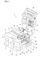
- Figure 1 is a perspective view of a fiber cleaver according to a first embodiment of the present invention seen from an operation side.
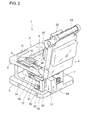
- Figure 2 is a perspective view of the fiber cleaver according to the first embodiment seen from the opposite side.
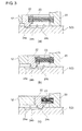
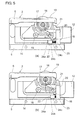
- Figure 3 includes cross-sectional views of an engaging member and a peripheral portion thereof; part (a), part (b), and part (c) illustrate the engaging member that is in engagement with first, second, and third recessed portions, respectively.
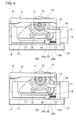
- Figure 4 includes side views of a main body of the fiber cleaver according to the first embodiment; part (a) illustrates a state where the engaging member is not in contact with a slider, and part (b) illustrates a state where the engaging member is in contact with the slider and is in engagement with the first recessed portion.
- Figure 5 includes side views of the main body of the fiber clever according to the first embodiment; part (a) illustrates a state where the engaging member is in contact with the slider and is in engagement with the second recessed portion, and part (b) illustrates a state where the engaging member is likewise in engagement with the third recessed portion.
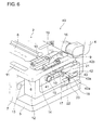
- Figure 6 is a perspective view illustrating a part of a fiber cleaver according to a second embodiment of the present invention.
- Figure 7 is a cross-sectional view illustrating a part of the fiber cleaver according to the second embodiment including a U-shaped protrusion.
- Figure 8 is a side view of the main body of the fiber cleaver according to the second embodiment in a state where the circular blade is being raised.
- Figure 1 is a perspective view of a fiber cleaver 1 according to a first embodiment of the present invention seen from an operation side.
- Figure 2 is a perspective view of the fiber cleaver 1 seen from the opposite side.
- the fiber cleaver 1 includes a main body 2 having a substantially I-shaped cross section, and a lid 4 openably and closably connected to the main body 2 with a shaft 3.
- the main body 2 includes a base 5, a mount 6 provided above the base 5, and a connecting portion 7 connecting the base 5 and the mount 6 to each other.
- the mount 6 has, in the upper surface thereof, a holder guide (fiber guiding portion) 8 that is a substantially rectangular recess and is provided for positioning a non-illustrated fiber holder.
- the mount 6 has, in a portion thereof adjacent to the holder guide 8, an opening 9 extending in the front-back direction of the main body 2 (in a direction orthogonal to the axis of the optical fiber to be placed on the mount 6 and in which a side nearer to an operation lever 29 is defined as front, and a side nearer to the shaft 3 is defined as rear).
- the mount 6 also has, on the upper surface thereof, a pair of lower clamps 10 having rubber members, respectively, and fixed on both sides of the opening 9.
- the mount 6 also has a magnet receiver 11 at the front end of the upper surface thereof.
- the main body 2 is provided with a slider 12 such that the slider 12 is movable in the front-back direction.
- the slider 12 is provided in a space between the base 5 and the mount 6 and moves in the front-back direction along a linear guide 13 provided in one side face of the connecting portion 7.
- the slider 12 is provided with a circular blade mounting bracket 14 fixed thereto with two screws 15.
- a circular blade 16 having a disc-like shape and configured to make a flaw in the optical fiber is attached to the circular-blade-mounting bracket 14 such that part of the circular blade 16 projects upward from the opening 9.
- the circular blade 16 is provided with a gear 17 (a rotary member). The circular blade 16 and the gear 17 are rotatable together with respect to the circular-blade-mounting bracket 14.
- the circular-blade-mounting bracket 14 is provided, at the lower rear thereof, with a pin 18 having a columnar shape and extending laterally with respect to the slider 12.
- the slider 12 is provided with a projection 19 provided at the top thereof and adjacent to the circular blade 16 in such a manner as to project upward from the opening 9.
- the base 5 is provided with a columnar protrusion 20 standing from the rear of the upper surface thereof.
- the columnar protrusion 20 is provided, at the upper end thereof, with an arm-like engaging member 21 (engaging portion) extending toward the front and configured to engage with the gear 17.
- Figure 3 includes cross-sectional views of an engaging member 22 and a peripheral portion thereof; part (a), part (b), and part (c) illustrate the engaging member 22 that is in engagement with first, second, and third recessed portions 24a, 24b, and 24c, respectively.
- the engaging member 22 is connected to the columnar protrusion 20 with a spring 23 interposed therebetween.
- the engaging member 22 is provided in the form of, for example, a ball plunger in which a spring is provided.
- Anchoring portions (the first recessed portion 24a to the third recessed portion 24c) that each position the engaging member 22 are provided in that order from the front side toward the rear side in the upper surface of the base 5 and on the front side with respect to the columnar protrusion 20.
- the first recessed portion 24a to the third recessed portion 24c each anchors the engaging member 22 when the lower end (a ball portion in the case of a ball plunger) of the engaging member 22 fits therein.
- the lid 4 is provided with an anvil 25 fixed to the back surface thereof.
- the anvil 25 has a rubber member and is configured to cleave the optical fiber by making a bend in the optical fiber in which a flaw has been made by the circular blade 16.
- the anvil 25 is urged by a non-illustrated spring in such a direction as to move away from the lid 4.
- the anvil 25 is provided with an engaging strip 26 configured to engage with the projection 19 when the lid 4 is closed in such a manner as to be placed onto the main body 2.
- the lid 4 is provided, on the back surface thereof, with a pair of upper clamps 27 having rubber members, respectively, and fixed on both sides of the anvil 25.
- the upper clamps 27 function in combination with the lower clamps 10, respectively, in such a manner as to clamp the optical fiber placed on the mount 6.
- the lid 4 is also provided, at the tip (front end) of the back surface thereof, with the operation lever 29 and a magnet 28 that is to be attracted to the magnet receiver 11.
- the optical fiber is first placed on the fiber holder. Subsequently, with the lid 4 open, the fiber holder is set in the holder guide 8 provided in the mount 6 of the main body 2.
- the lid 4 is closed. Then, the optical fiber is pinched between the clamps 10 and 27. Furthermore, the engaging strip 26 provided on the lid 4 comes into contact with the projection 19 of the slider 12, whereby the anvil 25 is retained in a state where the spring is compressed.
- the slider 12 is moved toward the rear with respect to the main body 2. Then, the circular blade 16 comes into contact with the optical fiber, whereby a flaw is made in the optical fiber.
- the projection 19 goes over the engaging strip 26.
- the anvil 25 is lowered by the restoring force of the spring and comes into contact with and pushes the optical fiber. Since the leading side and the trailing side of the optical fiber are held by the clamps 10 and 27, the optical fiber is bent. Consequently, the optical fiber breaks starting from the flaw that has been made therein.
- the slider 12 is not in contact with the engaging member 22 that is anchored at the first recessed portion 24a and, therefore, the gear 17 is not in contact with the engaging member 21 provided on the columnar protrusion 20 (part (a) of Fig. 4 ).
- the slider 12 in this state is further moved toward the rear, the slider 12 comes into contact with the engaging member 22 that is anchored at the first recessed portion 24a (part (b) of Fig. 4 ). In this state, however, the gear 17 is not in contact with the engaging member 21.
- the slider 12 When the slider 12 is further moved toward the rear, the slider 12 pushes the engaging member 22 such that the spring 23 is compressed.
- the lower end of the engaging member 22 goes out of the first recessed portion 24a and fits into the second recessed portion 24b, where the engaging member 22 is anchored (part (b) of Fig. 3 and part (a) of Fig. 5 ).
- the gear 17 comes into contact with the engaging member 21, and the engaging member 21 causes the gear 17 to rotate in the direction of the arrow by ⁇ degrees from the state illustrated in part (b) of Fig. 4 . Consequently, the circular blade 16 rotates by ⁇ degrees from the same state.
- the slider 12 When the slider 12 is further moved toward the rear, the slider 12 pushes the engaging member 22 such that the spring 23 is further compressed.
- the lower end of the engaging member 22 goes out of the second recessed portion 24b and fits into the third recessed portion 24c, where the engaging member 22 is anchored (part (c) of Fig. 3 and part (b) of Fig. 5 ).
- the engaging member 21 causes the gear 17 to further rotate in the direction of the arrow. Specifically, the gear 17 rotates by ⁇ (> ⁇ ) degrees from the state illustrated in part (b) of Fig. 4 . Consequently, the circular blade 16 rotates by ⁇ degrees from the same state.
- the angle of rotation of the circular blade 16 is simply changeable among three angles of zero degrees, ⁇ degrees, and ⁇ degrees in conjunction with the position where the engaging member 22 is anchored, the position being determined in accordance with the position of the slider 12 that is moved toward the rear with respect to the main body 2.
- the angle of rotation of the circular blade 16 is changeable stepwise in accordance with the condition of the circular blade 16 and so forth.
- the engaging member 22 is pushed with the slider 12 to the second recessed portion 24b (part (a) of Fig. 5 ) so that the point of contact of the circular blade 16 with respect to the optical fiber is changed.
- the circular blade 16 is rotated by ⁇ degrees.
- the slider 12 is returned to the initial position.
- the engaging member 22 is pushed with the slider 12 to the third recessed portion 24c (part (b) of Fig. 5 ) so that the point of contact of the circular blade 16 with respect to the optical fiber is further changed.
- the circular blade 16 is eventually rotated by ⁇ degrees.
- the slider 12 is returned to the initial position.
- the gear 17, the columnar protrusion 20, the engaging members 21 and 22, the spring 23, and the first recessed portion 24a to the third recessed portion 24c in combination form a circular-blade-rotating means that rotates the circular blade 16.
- the circular-blade-rotating means is configured to change the angle of rotation of the circular blade 16 in accordance with the position of the slider 12 that is moved with respect to the main body 2.
- the angle of rotation of the circular blade 16 changes stepwise by simply changing the position of the slider 12 with respect to the main body 2. Therefore, the circular blade 16 is rotatable without imposing extra workload on the worker. Furthermore, the angle of rotation of the circular blade 16 only needs to be set appropriately in accordance with the condition of the circular blade 16 including sharpness, chipping, and the like. Therefore, the circular blade 16 can be used efficiently over substantially the entirety of the circumference thereof. Consequently, the life of the circular blade 16 can be extended sufficiently. Moreover, appropriate part of the circular blade 16 that is sharp and has no chipping and the like can be always used in making a flaw in the optical fiber. Therefore, when the optical fiber is broken by using the anvil 25, the broken optical fiber is prevented from having a defective end facet.
- Figure 6 is a perspective view illustrating a part of a fiber cleaver 40 according to a second embodiment of the present invention.
- the fiber cleaver 40 includes the circular-blade-mounting bracket 14.
- the circular-blade-mounting bracket 14 is attached to the slider 12 with fixing springs 41, the fixing springs 41 being provided around the thread portions of the two screws 15, respectively. Therefore, the circular-blade-mounting bracket 14 is movable vertically with respect to the slider 12.
- the fiber cleaver 40 further includes, instead of the columnar protrusion 20, a U-shaped protrusion 42 including a lower wall portion 42a and an upper wall portion 42b.
- the upper surface of the lower wall portion 42a is substantially flush with the upper surface of the engaging member 22.
- a wedge 43 is provided on the upper surface of the lower wall portion 42a.
- the wedge 43 has a slant face 43a slanting upward from the front side toward the rear side of the main body 2.
- the slant face 43a engages with the pin 18 having a columnar shape and provided on the circular-blade-mounting bracket 14.
- the engaging member 21 is attached to the upper wall portion 42b.
- Figure 7 is a cross-sectional view illustrating a part of the fiber cleaver 40 including the U-shaped protrusion.
- a spring 44 that pushes up the wedge 43 is embedded in the lower wall portion 42a.
- An adjusting screw 45 for adjusting the level of the circular-blade-mounting bracket 14 with respect to the slider 12 is screwed in the upper wall portion 42b. The lower end of the adjusting screw 45 is in contact with the upper surface of the wedge 43. The length of movement of the pin 18 along the slant face 43a of the wedge 43 is adjusted with the adjusting screw 45, whereby the level of the circular-blade-mounting bracket 14 with respect to the slider 12 is adjustable.
- the circular-blade-mounting bracket 14, the screws 15, the pin 18, the fixing springs 41, the U-shaped protrusion 42, and the wedge 43 in combination form a circular-blade-raising means that raises the circular blade 16 with respect to the slider 12 after the circular blade 16 is rotated by the circular-blade-rotating means (described above).
- the circular blade can be raised with respect to the slider in a simple manner.
- the slider 12 is further pushed toward the rear from the state where the engaging member 22 is anchored at the third recessed portion 24c.
- the circular blade 16 is raised, whereby a flaw can be assuredly made in the optical fiber.
- the circular blade 16 becomes usable more efficiently.
- the life of the circular blade 16 can be extended, and the circular blade 16 can be used more efficiently.
- the circular blade 16 can be raised by simply moving the slider 12 toward the rear. Therefore, the workload imposed on the worker does not increase.
- the engaging member 22 that engages with the slider 12 does not necessarily have a configuration including a spring member such as the one described above and may include a latch mechanism, a gear mechanism, or the like.
- the angle of rotation of the circular blade 16 may be changed between two angles or among four or more angles including zero degrees.
- the angle of rotation of the circular blade 16 may be changed continuously with the position of the slider 12 with respect to the main body 2.
Landscapes
- Physics & Mathematics (AREA)
- General Physics & Mathematics (AREA)
- Optics & Photonics (AREA)
- Light Guides In General And Applications Therefor (AREA)
- Details Of Cutting Devices (AREA)
- Nonmetal Cutting Devices (AREA)
- Perforating, Stamping-Out Or Severing By Means Other Than Cutting (AREA)
Abstract
Description
- The present invention relates to a fiber cleaver.
- Japanese Unexamined Patent Application Publication No.
2001-296430 - In this fiber cleaver, if the circular blade is repeatedly used many times, the sharpness of the circular blade deteriorates. Therefore, it is proposed that the circular blade be rotatably attached to the slider and, when the sharpness of the circular blade has deteriorated, the circular blade is rotated by a certain angle such that the point of contact of the circular blade with respect to the optical fiber is changed. However, in such a case where the circular blade is rotated by the worker after members that fix the circular blade are loosened by the worker, the workload imposed on the worker increases and, moreover, it is difficult to appropriately change the point of contact of the circular blade with respect to the optical fiber. Hence, it is difficult to efficiently use the circular blade.
- It is an object of the present invention to provide a fiber cleaver in which a circular blade can be efficiently used without increasing the workload imposed on the worker.
- To achieve the above object, there is provided a fiber cleaver including a main body including a fiber guiding portion that positions an optical fiber, a slider movably provided to the main body, a circular blade rotatably provided to the slider and configured to make a flaw in the optical fiber, and a circular-blade-rotating means configured to change the angle of rotation of the circular blade in accordance with the position of the slider that is moved in one direction with respect to the main body.
- In a preferred embodiment, the circular-blade-rotating means of the fiber cleaver according to the present invention includes a rotary member configured to rotate together with the circular blade, and a protrusion fixed to the main body and including an engaging portion configured to engage with the rotary member. Furthermore, the circular-blade-rotating means preferably includes an engaging member provided to the protrusion with an elastic member interposed therebetween, the engaging member being configured to engage with the slider; and a plurality of anchoring portions provided to the main body and each configured to anchor the engaging member.
- In another preferred embodiment, the fiber cleaver according to the present invention further includes a circular-blade-raising means configured to raise the circular blade with respect to the slider after the circular blade is rotated by the circular-blade-rotating means. In this case, the circular-blade-raising means preferably includes a circular-blade-mounting bracket provided to the slider in such a manner as to be movable vertically and to which the circular blade is attached, a wedge fixed to the main body and having a slant face slanting upward in the one direction, and an engaging pin provided to the circular-blade-mounting bracket and configured to engage with the slant face.
- According to the present invention, the circular blade can be efficiently used without increasing the workload imposed on the worker, and the life of the circular blade can be extended.
-
Figure 1 is a perspective view of a fiber cleaver according to a first embodiment of the present invention seen from an operation side. -
Figure 2 is a perspective view of the fiber cleaver according to the first embodiment seen from the opposite side. -
Figure 3 includes cross-sectional views of an engaging member and a peripheral portion thereof; part (a), part (b), and part (c) illustrate the engaging member that is in engagement with first, second, and third recessed portions, respectively. -
Figure 4 includes side views of a main body of the fiber cleaver according to the first embodiment; part (a) illustrates a state where the engaging member is not in contact with a slider, and part (b) illustrates a state where the engaging member is in contact with the slider and is in engagement with the first recessed portion. -
Figure 5 includes side views of the main body of the fiber clever according to the first embodiment; part (a) illustrates a state where the engaging member is in contact with the slider and is in engagement with the second recessed portion, and part (b) illustrates a state where the engaging member is likewise in engagement with the third recessed portion. -
Figure 6 is a perspective view illustrating a part of a fiber cleaver according to a second embodiment of the present invention. -
Figure 7 is a cross-sectional view illustrating a part of the fiber cleaver according to the second embodiment including a U-shaped protrusion. -
Figure 8 is a side view of the main body of the fiber cleaver according to the second embodiment in a state where the circular blade is being raised. - Embodiments of the present invention will now be described with reference to the drawings. The drawings are only for illustration and do not limit the scope of the invention. In the drawings, identical reference numerals denote same elements so that redundant description is avoided. The scale ratio in the drawings is not necessarily exact.
-
Figure 1 is a perspective view of afiber cleaver 1 according to a first embodiment of the present invention seen from an operation side.Figure 2 is a perspective view of thefiber cleaver 1 seen from the opposite side. Thefiber cleaver 1 includes amain body 2 having a substantially I-shaped cross section, and alid 4 openably and closably connected to themain body 2 with ashaft 3. Themain body 2 includes abase 5, amount 6 provided above thebase 5, and a connectingportion 7 connecting thebase 5 and themount 6 to each other. - The
mount 6 has, in the upper surface thereof, a holder guide (fiber guiding portion) 8 that is a substantially rectangular recess and is provided for positioning a non-illustrated fiber holder. Themount 6 has, in a portion thereof adjacent to theholder guide 8, anopening 9 extending in the front-back direction of the main body 2 (in a direction orthogonal to the axis of the optical fiber to be placed on themount 6 and in which a side nearer to anoperation lever 29 is defined as front, and a side nearer to theshaft 3 is defined as rear). Themount 6 also has, on the upper surface thereof, a pair oflower clamps 10 having rubber members, respectively, and fixed on both sides of theopening 9. Themount 6 also has amagnet receiver 11 at the front end of the upper surface thereof. - The
main body 2 is provided with aslider 12 such that theslider 12 is movable in the front-back direction. Theslider 12 is provided in a space between thebase 5 and themount 6 and moves in the front-back direction along alinear guide 13 provided in one side face of the connectingportion 7. - The
slider 12 is provided with a circularblade mounting bracket 14 fixed thereto with twoscrews 15. Acircular blade 16 having a disc-like shape and configured to make a flaw in the optical fiber is attached to the circular-blade-mounting bracket 14 such that part of thecircular blade 16 projects upward from theopening 9. Thecircular blade 16 is provided with a gear 17 (a rotary member). Thecircular blade 16 and thegear 17 are rotatable together with respect to the circular-blade-mounting bracket 14. - The circular-blade-
mounting bracket 14 is provided, at the lower rear thereof, with apin 18 having a columnar shape and extending laterally with respect to theslider 12. Theslider 12 is provided with aprojection 19 provided at the top thereof and adjacent to thecircular blade 16 in such a manner as to project upward from theopening 9. - The
base 5 is provided with acolumnar protrusion 20 standing from the rear of the upper surface thereof. Thecolumnar protrusion 20 is provided, at the upper end thereof, with an arm-like engaging member 21 (engaging portion) extending toward the front and configured to engage with thegear 17. -
Figure 3 includes cross-sectional views of anengaging member 22 and a peripheral portion thereof; part (a), part (b), and part (c) illustrate theengaging member 22 that is in engagement with first, second, and third recessedportions engaging member 22, which has a substantially block-like shape and is configured to engage with theslider 12, is provided on the front side with respect to thecolumnar protrusion 20. Theengaging member 22 is connected to thecolumnar protrusion 20 with aspring 23 interposed therebetween. Theengaging member 22 is provided in the form of, for example, a ball plunger in which a spring is provided. Anchoring portions (the first recessedportion 24a to the third recessedportion 24c) that each position theengaging member 22 are provided in that order from the front side toward the rear side in the upper surface of thebase 5 and on the front side with respect to thecolumnar protrusion 20. The firstrecessed portion 24a to the third recessedportion 24c each anchors theengaging member 22 when the lower end (a ball portion in the case of a ball plunger) of theengaging member 22 fits therein. - As
Figs. 1 and2 show, thelid 4 is provided with ananvil 25 fixed to the back surface thereof. Theanvil 25 has a rubber member and is configured to cleave the optical fiber by making a bend in the optical fiber in which a flaw has been made by thecircular blade 16. Theanvil 25 is urged by a non-illustrated spring in such a direction as to move away from thelid 4. Theanvil 25 is provided with anengaging strip 26 configured to engage with theprojection 19 when thelid 4 is closed in such a manner as to be placed onto themain body 2. - The
lid 4 is provided, on the back surface thereof, with a pair ofupper clamps 27 having rubber members, respectively, and fixed on both sides of theanvil 25. Theupper clamps 27 function in combination with thelower clamps 10, respectively, in such a manner as to clamp the optical fiber placed on themount 6. Thelid 4 is also provided, at the tip (front end) of the back surface thereof, with theoperation lever 29 and amagnet 28 that is to be attracted to themagnet receiver 11. - To cleave an optical fiber with the
fiber cleaver 1, the optical fiber is first placed on the fiber holder. Subsequently, with thelid 4 open, the fiber holder is set in theholder guide 8 provided in themount 6 of themain body 2. - Subsequently, in a state where the
slider 12 is at the frontmost position (initial position) with respect to themain body 2, thelid 4 is closed. Then, the optical fiber is pinched between theclamps strip 26 provided on thelid 4 comes into contact with theprojection 19 of theslider 12, whereby theanvil 25 is retained in a state where the spring is compressed. - Subsequently, the
slider 12 is moved toward the rear with respect to themain body 2. Then, thecircular blade 16 comes into contact with the optical fiber, whereby a flaw is made in the optical fiber. - When the
slider 12 is further moved toward the rear, theprojection 19 goes over the engagingstrip 26. Hence, theanvil 25 is lowered by the restoring force of the spring and comes into contact with and pushes the optical fiber. Since the leading side and the trailing side of the optical fiber are held by theclamps - Immediately after the optical fiber is cleaved as described above, the
slider 12 is not in contact with the engagingmember 22 that is anchored at the first recessedportion 24a and, therefore, thegear 17 is not in contact with the engagingmember 21 provided on the columnar protrusion 20 (part (a) ofFig. 4 ). When theslider 12 in this state is further moved toward the rear, theslider 12 comes into contact with the engagingmember 22 that is anchored at the first recessedportion 24a (part (b) ofFig. 4 ). In this state, however, thegear 17 is not in contact with the engagingmember 21. - When the
slider 12 is further moved toward the rear, theslider 12 pushes the engagingmember 22 such that thespring 23 is compressed. Thus, the lower end of the engagingmember 22 goes out of the first recessedportion 24a and fits into the second recessedportion 24b, where the engagingmember 22 is anchored (part (b) ofFig. 3 and part (a) ofFig. 5 ). In this process, thegear 17 comes into contact with the engagingmember 21, and the engagingmember 21 causes thegear 17 to rotate in the direction of the arrow by α degrees from the state illustrated in part (b) ofFig. 4 . Consequently, thecircular blade 16 rotates by α degrees from the same state. - When the
slider 12 is further moved toward the rear, theslider 12 pushes the engagingmember 22 such that thespring 23 is further compressed. Thus, the lower end of the engagingmember 22 goes out of the second recessedportion 24b and fits into the third recessedportion 24c, where the engagingmember 22 is anchored (part (c) ofFig. 3 and part (b) ofFig. 5 ). In this process, the engagingmember 21 causes thegear 17 to further rotate in the direction of the arrow. Specifically, thegear 17 rotates by β (>α) degrees from the state illustrated in part (b) ofFig. 4 . Consequently, thecircular blade 16 rotates by β degrees from the same state. - As described above, the angle of rotation of the
circular blade 16 is simply changeable among three angles of zero degrees, α degrees, and β degrees in conjunction with the position where the engagingmember 22 is anchored, the position being determined in accordance with the position of theslider 12 that is moved toward the rear with respect to themain body 2. Thus, the angle of rotation of thecircular blade 16 is changeable stepwise in accordance with the condition of thecircular blade 16 and so forth. - Specifically, if there is no special problem with the sharpness of the
circular blade 16 in the last performance of cleaving the optical fiber, there is no need to change the point of contact of thecircular blade 16 with respect to the optical fiber. Therefore, when theslider 12 comes into contact with the engaging member 22 (part (b) ofFig. 4 ), theslider 12 is returned to the initial position. That is, theslider 12 is returned to the initial position without rotating thecircular blade 16. - If it is determined that the sharpness of the
circular blade 16 has deteriorated in the last performance of cleaving the optical fiber, the engagingmember 22 is pushed with theslider 12 to the second recessedportion 24b (part (a) ofFig. 5 ) so that the point of contact of thecircular blade 16 with respect to the optical fiber is changed. Thus, thecircular blade 16 is rotated by α degrees. Subsequently, theslider 12 is returned to the initial position. - However, for example, if there are any chipping or the like at the point of contact of the
circular blade 16 with respect to the optical fiber in a state where thecircular blade 16 has been rotated by α degrees, the engagingmember 22 is pushed with theslider 12 to the third recessedportion 24c (part (b) ofFig. 5 ) so that the point of contact of thecircular blade 16 with respect to the optical fiber is further changed. Thus, thecircular blade 16 is eventually rotated by β degrees. Subsequently, theslider 12 is returned to the initial position. - In the above configuration, the
gear 17, thecolumnar protrusion 20, the engagingmembers spring 23, and the first recessedportion 24a to the third recessedportion 24c in combination form a circular-blade-rotating means that rotates thecircular blade 16. The circular-blade-rotating means is configured to change the angle of rotation of thecircular blade 16 in accordance with the position of theslider 12 that is moved with respect to themain body 2. - As described above, in the
fiber cleaver 1 according to the first embodiment, the angle of rotation of thecircular blade 16 changes stepwise by simply changing the position of theslider 12 with respect to themain body 2. Therefore, thecircular blade 16 is rotatable without imposing extra workload on the worker. Furthermore, the angle of rotation of thecircular blade 16 only needs to be set appropriately in accordance with the condition of thecircular blade 16 including sharpness, chipping, and the like. Therefore, thecircular blade 16 can be used efficiently over substantially the entirety of the circumference thereof. Consequently, the life of thecircular blade 16 can be extended sufficiently. Moreover, appropriate part of thecircular blade 16 that is sharp and has no chipping and the like can be always used in making a flaw in the optical fiber. Therefore, when the optical fiber is broken by using theanvil 25, the broken optical fiber is prevented from having a defective end facet. -
Figure 6 is a perspective view illustrating a part of afiber cleaver 40 according to a second embodiment of the present invention. As with thefiber cleaver 1, thefiber cleaver 40 includes the circular-blade-mountingbracket 14. Unlike that of thefiber cleaver 1, the circular-blade-mountingbracket 14 is attached to theslider 12 with fixingsprings 41, the fixing springs 41 being provided around the thread portions of the twoscrews 15, respectively. Therefore, the circular-blade-mountingbracket 14 is movable vertically with respect to theslider 12. - The
fiber cleaver 40 further includes, instead of thecolumnar protrusion 20, aU-shaped protrusion 42 including alower wall portion 42a and anupper wall portion 42b. The upper surface of thelower wall portion 42a is substantially flush with the upper surface of the engagingmember 22. Awedge 43 is provided on the upper surface of thelower wall portion 42a. Thewedge 43 has aslant face 43a slanting upward from the front side toward the rear side of themain body 2. Theslant face 43a engages with thepin 18 having a columnar shape and provided on the circular-blade-mountingbracket 14. The engagingmember 21 is attached to theupper wall portion 42b. -
Figure 7 is a cross-sectional view illustrating a part of thefiber cleaver 40 including the U-shaped protrusion. Aspring 44 that pushes up thewedge 43 is embedded in thelower wall portion 42a. An adjustingscrew 45 for adjusting the level of the circular-blade-mountingbracket 14 with respect to theslider 12 is screwed in theupper wall portion 42b. The lower end of the adjustingscrew 45 is in contact with the upper surface of thewedge 43. The length of movement of thepin 18 along theslant face 43a of thewedge 43 is adjusted with the adjustingscrew 45, whereby the level of the circular-blade-mountingbracket 14 with respect to theslider 12 is adjustable. - When the
fiber cleaver 40 is in a state where the engagingmember 22 is anchored at the third recessedportion 24c, thepin 18 is in contact with the slant face 43 a of thewedge 43. In this state, when theslider 12 is further pushed toward the rear, thepin 18 goes up theslant face 43a (Fig. 8 ). Therefore, the circular-blade-mountingbracket 14 moves upward with respect to theslider 12. As a result, thecircular blade member 16 is raised. Here, an amount of rising y of thecircular blade 16 is arbitrarily adjustable with the adjustingscrew 45. Meanwhile, the fixing springs 41 retain the position of the circular-blade-mountingbracket 14 with respect to theslider 12. - In the above configuration, the circular-blade-mounting
bracket 14, thescrews 15, thepin 18, the fixing springs 41, theU-shaped protrusion 42, and thewedge 43 in combination form a circular-blade-raising means that raises thecircular blade 16 with respect to theslider 12 after thecircular blade 16 is rotated by the circular-blade-rotating means (described above). With this configuration, the circular blade can be raised with respect to the slider in a simple manner. - As described above, according to the second embodiment, if it becomes difficult to make a flaw in an optical fiber at any point of the circular blade because the
circular blade 16 has become dull over the entirety of the circumference thereof, theslider 12 is further pushed toward the rear from the state where the engagingmember 22 is anchored at the third recessedportion 24c. As a result, thecircular blade 16 is raised, whereby a flaw can be assuredly made in the optical fiber. Thus, thecircular blade 16 becomes usable more efficiently. Hence, the life of thecircular blade 16 can be extended, and thecircular blade 16 can be used more efficiently. Furthermore, thecircular blade 16 can be raised by simply moving theslider 12 toward the rear. Therefore, the workload imposed on the worker does not increase. - The present invention is not limited to the above embodiments. For example, the engaging
member 22 that engages with theslider 12 does not necessarily have a configuration including a spring member such as the one described above and may include a latch mechanism, a gear mechanism, or the like. Furthermore, the angle of rotation of thecircular blade 16 may be changed between two angles or among four or more angles including zero degrees. Moreover, the angle of rotation of thecircular blade 16 may be changed continuously with the position of theslider 12 with respect to themain body 2. - PTL 1: Japanese Unexamined Patent Application Publication No.
2001-296430
Claims (5)
- A fiber cleaver comprising:a main body including a fiber guiding portion that positions an optical fiber;a slider movably provided to the main body;a circular blade rotatably provided to the slider and configured to make a flaw in the optical fiber; anda circular-blade-rotating means configured to change the angle of rotation of the circular blade in accordance with the position of the slider that is moved in one direction with respect to the main body.
- The fiber cleaver according to Claim 1,
wherein the circular-blade-rotating means includes
a rotary member configured to rotate together with the circular blade; and
a protrusion fixed to the main body and including an engaging portion configured to engage with the rotary member. - The fiber cleaver according to Claim 2,
wherein the circular-blade-rotating means further includes
an engaging member provided to the protrusion with an elastic member interposed therebetween, the engaging member being configured to engage with the slider; and
a plurality of anchoring portions provided to the main body and each configured to anchor the engaging member. - The fiber cleaver according to any of Claims 1 to 3, further comprising a circular-blade-raising means configured to raise the circular blade with respect to the slider after the circular blade is rotated by the circular-blade-rotating means.
- The fiber cleaver according to Claim 4,
wherein the circular-blade-raising means includes
a circular-blade-mounting bracket provided to the slider in such a manner as to be movable vertically and to which the circular blade is attached;
a wedge fixed to the main body and having a slant face slanting upward in the one direction; and
an engaging pin provided to the circular-blade-mounting bracket and configured to engage with the slant face.
Applications Claiming Priority (2)
| Application Number | Priority Date | Filing Date | Title |
|---|---|---|---|
| JP2010146523A JP5200064B2 (en) | 2010-06-28 | 2010-06-28 | Optical fiber cutter |
| PCT/JP2011/064217 WO2012002202A1 (en) | 2010-06-28 | 2011-06-22 | Optical fiber cutter |
Publications (3)
| Publication Number | Publication Date |
|---|---|
| EP2587286A1 true EP2587286A1 (en) | 2013-05-01 |
| EP2587286A4 EP2587286A4 (en) | 2015-01-28 |
| EP2587286B1 EP2587286B1 (en) | 2017-11-08 |
Family
ID=45401922
Family Applications (1)
| Application Number | Title | Priority Date | Filing Date |
|---|---|---|---|
| EP11800667.5A Active EP2587286B1 (en) | 2010-06-28 | 2011-06-22 | Optical fiber cutter |
Country Status (9)
| Country | Link |
|---|---|
| US (1) | US9016535B2 (en) |
| EP (1) | EP2587286B1 (en) |
| JP (1) | JP5200064B2 (en) |
| KR (2) | KR20130039318A (en) |
| CN (1) | CN102971651B (en) |
| CA (1) | CA2803988C (en) |
| MY (1) | MY161920A (en) |
| SG (1) | SG186175A1 (en) |
| WO (1) | WO2012002202A1 (en) |
Families Citing this family (26)
| Publication number | Priority date | Publication date | Assignee | Title |
|---|---|---|---|---|
| US10773420B2 (en) * | 2011-11-10 | 2020-09-15 | LatticeGear, LLC | Device and method for cleaving a substrate |
| US9726823B2 (en) * | 2012-02-20 | 2017-08-08 | Inno Instrument (China) Inc. | Optical fiber cutting knife |
| CN203202149U (en) * | 2013-04-03 | 2013-09-18 | 深圳日海通讯技术股份有限公司 | Ratchet wheel mechanism |
| CN103529515B (en) * | 2013-10-30 | 2016-08-17 | 上海电缆研究所 | Optical fiber coating method for treating end face and device |
| USD745816S1 (en) * | 2013-12-16 | 2015-12-22 | Dh Infotech (Weihai) Inc. | Optical fiber cleaver |
| WO2016044668A1 (en) * | 2014-09-17 | 2016-03-24 | Nanoprecision Procucts, Inc. | A tensioning device having a flexure mechanism for applying axial tension to cleave an optical fiber |
| CN105345276B (en) * | 2015-11-22 | 2017-08-04 | 苏州光韵达光电科技有限公司 | A kind of optical fiber cutter on optical-fiber laser cutting machine |
| CN105511019B (en) * | 2015-12-30 | 2018-07-31 | 合肥信维仪器有限公司 | Improve the fiber cut breaker of cutting slice mounting structure |
| JP6623490B2 (en) * | 2016-02-12 | 2019-12-25 | Seiオプティフロンティア株式会社 | Optical fiber cutting equipment |
| JP6593794B2 (en) * | 2016-02-12 | 2019-10-23 | Seiオプティフロンティア株式会社 | Optical fiber holder and optical fiber cutting device to which the optical fiber holder can be attached |
| JP6673712B2 (en) * | 2016-02-12 | 2020-03-25 | Seiオプティフロンティア株式会社 | Optical fiber cutting equipment |
| JP6611008B2 (en) * | 2016-02-29 | 2019-11-27 | Seiオプティフロンティア株式会社 | Optical fiber cutter |
| JP6639955B2 (en) * | 2016-02-29 | 2020-02-05 | Seiオプティフロンティア株式会社 | Optical fiber cutter |
| CN105618937B (en) * | 2016-03-08 | 2017-08-04 | 浙江乔兴建设集团湖州智能科技有限公司 | A kind of modular fiber optic cutter device |
| KR101779405B1 (en) | 2016-12-19 | 2017-09-19 | 일신테크(주) | The apparatus of cutting a optical fiber for auto uniform rotating of blade |
| JP6244491B1 (en) | 2017-03-06 | 2017-12-06 | 株式会社フジクラ | Optical fiber cutting device |
| US10591673B2 (en) * | 2017-04-04 | 2020-03-17 | Fujikura Ltd. | Optical fiber cutting system |
| JP6785211B2 (en) * | 2017-11-30 | 2020-11-18 | 株式会社フジクラ | Fiber optic cutting system |
| ES2957333T3 (en) * | 2017-12-12 | 2024-01-17 | Sumitomo Electric Industries | Fiber optic cutter and fiber optic cutting method |
| US10739517B2 (en) * | 2018-09-21 | 2020-08-11 | Ofs Fitel, Llc | Cleaving optical fibers |
| JP6998910B2 (en) * | 2019-03-08 | 2022-01-18 | 古河電気工業株式会社 | Cutting device |
| CN110780385A (en) * | 2019-11-26 | 2020-02-11 | 杭州雷特通信技术有限公司 | A standard termination tool for optical fiber fusion-free connection |
| KR20230169996A (en) * | 2021-04-19 | 2023-12-18 | 스미토모 덴코 옵티프론티어 가부시키가이샤 | optical fiber cutting device |
| US12631825B2 (en) * | 2021-07-02 | 2026-05-19 | Sumitomo Electric Optifrontier Co., Ltd. | Optical fiber cutter |
| EP4367762B1 (en) * | 2021-07-09 | 2026-07-15 | Hubbell Power Systems, Inc. | Cable shaving tool |
| CN120344892A (en) * | 2022-12-27 | 2025-07-18 | 古河电气工业株式会社 | Cutting device |
Family Cites Families (17)
| Publication number | Priority date | Publication date | Assignee | Title |
|---|---|---|---|---|
| US5123581A (en) * | 1991-01-04 | 1992-06-23 | Bell Communications Research, Inc. | Oblique fracturing of optical fibers by offset shearing |
| JP3490259B2 (en) * | 1997-07-22 | 2004-01-26 | 株式会社マキタ | Circular saw |
| JP4403478B2 (en) | 2000-04-11 | 2010-01-27 | 住友電気工業株式会社 | Optical fiber cutter |
| TW545365U (en) * | 2001-12-13 | 2003-08-01 | Ind Tech Res Inst | Handheld optical fiber cutting apparatus |
| CN2522230Y (en) * | 2002-01-30 | 2002-11-27 | 财团法人工业技术研究院 | Handheld Fiber Cleaving Device |
| AU2003261613A1 (en) | 2002-08-26 | 2004-09-17 | Ilsin Precision Co., Ltd. | Automatic optical-fiber cutter |
| US7669744B2 (en) * | 2003-08-04 | 2010-03-02 | 3M Innovative Properties Company | Device and method for cleaving optical fibers |
| JP4413679B2 (en) | 2004-04-15 | 2010-02-10 | 古河電気工業株式会社 | Optical fiber cutting device and optical fiber cutting method |
| JP2006251034A (en) * | 2005-03-08 | 2006-09-21 | Fujikura Ltd | Optical fiber cutting device |
| JP4650296B2 (en) * | 2006-02-22 | 2011-03-16 | 日立工機株式会社 | Tabletop cutting machine |
| KR20080037498A (en) | 2006-10-26 | 2008-04-30 | 일신테크(주) | Fiber optic cutting machine |
| US20100163593A1 (en) * | 2006-10-26 | 2010-07-01 | Jae Seop Song | Optical fiber cleaver |
| CN200972517Y (en) * | 2006-11-16 | 2007-11-07 | 南京吉隆光纤通信有限公司 | Motion mechanism of cutting component of optical fibre cutter |
| CA2618617C (en) * | 2007-01-23 | 2016-03-29 | Sumitomo Electric Industries, Ltd. | Optical fiber cutting device |
| JP5065800B2 (en) * | 2007-01-23 | 2012-11-07 | 住友電気工業株式会社 | Optical fiber cutting device |
| JP4956474B2 (en) * | 2008-03-28 | 2012-06-20 | 古河電気工業株式会社 | Optical fiber cutting device |
| JP5217011B2 (en) * | 2011-03-17 | 2013-06-19 | Seiオプティフロンティア株式会社 | Optical fiber cutter |
-
2010
- 2010-06-28 JP JP2010146523A patent/JP5200064B2/en active Active
-
2011
- 2011-06-22 KR KR1020127034035A patent/KR20130039318A/en not_active Ceased
- 2011-06-22 MY MYPI2012701207A patent/MY161920A/en unknown
- 2011-06-22 US US13/701,311 patent/US9016535B2/en active Active
- 2011-06-22 EP EP11800667.5A patent/EP2587286B1/en active Active
- 2011-06-22 CA CA2803988A patent/CA2803988C/en active Active
- 2011-06-22 CN CN201180031754.8A patent/CN102971651B/en active Active
- 2011-06-22 KR KR1020157008305A patent/KR101586981B1/en active Active
- 2011-06-22 WO PCT/JP2011/064217 patent/WO2012002202A1/en not_active Ceased
- 2011-06-22 SG SG2012089314A patent/SG186175A1/en unknown
Also Published As
| Publication number | Publication date |
|---|---|
| SG186175A1 (en) | 2013-01-30 |
| CN102971651A (en) | 2013-03-13 |
| JP5200064B2 (en) | 2013-05-15 |
| JP2012008472A (en) | 2012-01-12 |
| US9016535B2 (en) | 2015-04-28 |
| CA2803988C (en) | 2017-08-29 |
| WO2012002202A1 (en) | 2012-01-05 |
| KR20130039318A (en) | 2013-04-19 |
| EP2587286A4 (en) | 2015-01-28 |
| US20130075440A1 (en) | 2013-03-28 |
| CA2803988A1 (en) | 2012-01-05 |
| KR20150043528A (en) | 2015-04-22 |
| EP2587286B1 (en) | 2017-11-08 |
| MY161920A (en) | 2017-05-15 |
| CN102971651B (en) | 2015-06-10 |
| KR101586981B1 (en) | 2016-01-20 |
Similar Documents
| Publication | Publication Date | Title |
|---|---|---|
| US9016535B2 (en) | Fiber cleaver | |
| CN101231366B (en) | Optical fiber cutting device | |
| US9395492B2 (en) | Optical fiber cutter | |
| US8430889B2 (en) | Puncture needle holder | |
| KR101300937B1 (en) | Apparatus for cutting optical fiber | |
| US7784388B2 (en) | Blade clamping device | |
| JP2000190125A (en) | Cutting tool mounting device for reciprocating cutting tools | |
| KR102372461B1 (en) | Optical fiber cutting apparatus | |
| RU2484948C2 (en) | Jig for circular cutoff saw for oblique cutting and circular cutoff saw for oblique cutting | |
| JP2017142458A (en) | Optical fiber cutting device | |
| JP2010264004A (en) | Cutter knife | |
| JP7361433B1 (en) | Holder for circular blades | |
| CN110919435B (en) | Cutter clamping structure of cutter changing mechanism | |
| EP1870362A1 (en) | Tape cutter and tape holder | |
| JP2011103995A (en) | Cutting device for rolled paper and rolled paper holder using the same | |
| JP2010540856A5 (en) | ||
| JP7361432B1 (en) | Holder for circular blades | |
| JP2011133787A (en) | Optical fiber slant-cutting device and optical fiber slant-cutting method | |
| JP2014105955A (en) | Archery target fixing tool | |
| JP2001296431A (en) | Optical fiber cutter | |
| KR20110066048A (en) | Device to prevent pinching of saw blades used for cutting pipe or bar | |
| JP2005134584A (en) | Optical fiber connection tool |
Legal Events
| Date | Code | Title | Description |
|---|---|---|---|
| PUAI | Public reference made under article 153(3) epc to a published international application that has entered the european phase |
Free format text: ORIGINAL CODE: 0009012 |
|
| 17P | Request for examination filed |
Effective date: 20121219 |
|
| AK | Designated contracting states |
Kind code of ref document: A1 Designated state(s): AL AT BE BG CH CY CZ DE DK EE ES FI FR GB GR HR HU IE IS IT LI LT LU LV MC MK MT NL NO PL PT RO RS SE SI SK SM TR |
|
| DAX | Request for extension of the european patent (deleted) | ||
| A4 | Supplementary search report drawn up and despatched |
Effective date: 20150109 |
|
| RIC1 | Information provided on ipc code assigned before grant |
Ipc: G02B 6/00 20060101AFI20141223BHEP Ipc: G02B 6/25 20060101ALI20141223BHEP |
|
| GRAP | Despatch of communication of intention to grant a patent |
Free format text: ORIGINAL CODE: EPIDOSNIGR1 |
|
| STAA | Information on the status of an ep patent application or granted ep patent |
Free format text: STATUS: GRANT OF PATENT IS INTENDED |
|
| INTG | Intention to grant announced |
Effective date: 20170710 |
|
| RIN1 | Information on inventor provided before grant (corrected) |
Inventor name: HASEGAWA, MASAHIRO Inventor name: HOMMA, TOSHIHIKO |
|
| GRAS | Grant fee paid |
Free format text: ORIGINAL CODE: EPIDOSNIGR3 |
|
| GRAA | (expected) grant |
Free format text: ORIGINAL CODE: 0009210 |
|
| STAA | Information on the status of an ep patent application or granted ep patent |
Free format text: STATUS: THE PATENT HAS BEEN GRANTED |
|
| AK | Designated contracting states |
Kind code of ref document: B1 Designated state(s): AL AT BE BG CH CY CZ DE DK EE ES FI FR GB GR HR HU IE IS IT LI LT LU LV MC MK MT NL NO PL PT RO RS SE SI SK SM TR |
|
| REG | Reference to a national code |
Ref country code: GB Ref legal event code: FG4D |
|
| REG | Reference to a national code |
Ref country code: CH Ref legal event code: EP Ref country code: AT Ref legal event code: REF Ref document number: 944673 Country of ref document: AT Kind code of ref document: T Effective date: 20171115 |
|
| REG | Reference to a national code |
Ref country code: IE Ref legal event code: FG4D |
|
| REG | Reference to a national code |
Ref country code: DE Ref legal event code: R096 Ref document number: 602011043206 Country of ref document: DE |
|
| REG | Reference to a national code |
Ref country code: NL Ref legal event code: MP Effective date: 20171108 |
|
| REG | Reference to a national code |
Ref country code: LT Ref legal event code: MG4D |
|
| REG | Reference to a national code |
Ref country code: AT Ref legal event code: MK05 Ref document number: 944673 Country of ref document: AT Kind code of ref document: T Effective date: 20171108 |
|
| PG25 | Lapsed in a contracting state [announced via postgrant information from national office to epo] |
Ref country code: NO Free format text: LAPSE BECAUSE OF FAILURE TO SUBMIT A TRANSLATION OF THE DESCRIPTION OR TO PAY THE FEE WITHIN THE PRESCRIBED TIME-LIMIT Effective date: 20180208 Ref country code: SE Free format text: LAPSE BECAUSE OF FAILURE TO SUBMIT A TRANSLATION OF THE DESCRIPTION OR TO PAY THE FEE WITHIN THE PRESCRIBED TIME-LIMIT Effective date: 20171108 Ref country code: ES Free format text: LAPSE BECAUSE OF FAILURE TO SUBMIT A TRANSLATION OF THE DESCRIPTION OR TO PAY THE FEE WITHIN THE PRESCRIBED TIME-LIMIT Effective date: 20171108 Ref country code: NL Free format text: LAPSE BECAUSE OF FAILURE TO SUBMIT A TRANSLATION OF THE DESCRIPTION OR TO PAY THE FEE WITHIN THE PRESCRIBED TIME-LIMIT Effective date: 20171108 Ref country code: FI Free format text: LAPSE BECAUSE OF FAILURE TO SUBMIT A TRANSLATION OF THE DESCRIPTION OR TO PAY THE FEE WITHIN THE PRESCRIBED TIME-LIMIT Effective date: 20171108 Ref country code: LT Free format text: LAPSE BECAUSE OF FAILURE TO SUBMIT A TRANSLATION OF THE DESCRIPTION OR TO PAY THE FEE WITHIN THE PRESCRIBED TIME-LIMIT Effective date: 20171108 |
|
| REG | Reference to a national code |
Ref country code: FR Ref legal event code: PLFP Year of fee payment: 8 |
|
| PG25 | Lapsed in a contracting state [announced via postgrant information from national office to epo] |
Ref country code: BG Free format text: LAPSE BECAUSE OF FAILURE TO SUBMIT A TRANSLATION OF THE DESCRIPTION OR TO PAY THE FEE WITHIN THE PRESCRIBED TIME-LIMIT Effective date: 20180208 Ref country code: RS Free format text: LAPSE BECAUSE OF FAILURE TO SUBMIT A TRANSLATION OF THE DESCRIPTION OR TO PAY THE FEE WITHIN THE PRESCRIBED TIME-LIMIT Effective date: 20171108 Ref country code: LV Free format text: LAPSE BECAUSE OF FAILURE TO SUBMIT A TRANSLATION OF THE DESCRIPTION OR TO PAY THE FEE WITHIN THE PRESCRIBED TIME-LIMIT Effective date: 20171108 Ref country code: AT Free format text: LAPSE BECAUSE OF FAILURE TO SUBMIT A TRANSLATION OF THE DESCRIPTION OR TO PAY THE FEE WITHIN THE PRESCRIBED TIME-LIMIT Effective date: 20171108 Ref country code: IS Free format text: LAPSE BECAUSE OF FAILURE TO SUBMIT A TRANSLATION OF THE DESCRIPTION OR TO PAY THE FEE WITHIN THE PRESCRIBED TIME-LIMIT Effective date: 20180308 Ref country code: HR Free format text: LAPSE BECAUSE OF FAILURE TO SUBMIT A TRANSLATION OF THE DESCRIPTION OR TO PAY THE FEE WITHIN THE PRESCRIBED TIME-LIMIT Effective date: 20171108 Ref country code: GR Free format text: LAPSE BECAUSE OF FAILURE TO SUBMIT A TRANSLATION OF THE DESCRIPTION OR TO PAY THE FEE WITHIN THE PRESCRIBED TIME-LIMIT Effective date: 20180209 |
|
| PG25 | Lapsed in a contracting state [announced via postgrant information from national office to epo] |
Ref country code: CY Free format text: LAPSE BECAUSE OF FAILURE TO SUBMIT A TRANSLATION OF THE DESCRIPTION OR TO PAY THE FEE WITHIN THE PRESCRIBED TIME-LIMIT Effective date: 20171108 Ref country code: EE Free format text: LAPSE BECAUSE OF FAILURE TO SUBMIT A TRANSLATION OF THE DESCRIPTION OR TO PAY THE FEE WITHIN THE PRESCRIBED TIME-LIMIT Effective date: 20171108 Ref country code: DK Free format text: LAPSE BECAUSE OF FAILURE TO SUBMIT A TRANSLATION OF THE DESCRIPTION OR TO PAY THE FEE WITHIN THE PRESCRIBED TIME-LIMIT Effective date: 20171108 Ref country code: CZ Free format text: LAPSE BECAUSE OF FAILURE TO SUBMIT A TRANSLATION OF THE DESCRIPTION OR TO PAY THE FEE WITHIN THE PRESCRIBED TIME-LIMIT Effective date: 20171108 Ref country code: SK Free format text: LAPSE BECAUSE OF FAILURE TO SUBMIT A TRANSLATION OF THE DESCRIPTION OR TO PAY THE FEE WITHIN THE PRESCRIBED TIME-LIMIT Effective date: 20171108 |
|
| REG | Reference to a national code |
Ref country code: DE Ref legal event code: R097 Ref document number: 602011043206 Country of ref document: DE |
|
| PG25 | Lapsed in a contracting state [announced via postgrant information from national office to epo] |
Ref country code: PL Free format text: LAPSE BECAUSE OF FAILURE TO SUBMIT A TRANSLATION OF THE DESCRIPTION OR TO PAY THE FEE WITHIN THE PRESCRIBED TIME-LIMIT Effective date: 20171108 Ref country code: SM Free format text: LAPSE BECAUSE OF FAILURE TO SUBMIT A TRANSLATION OF THE DESCRIPTION OR TO PAY THE FEE WITHIN THE PRESCRIBED TIME-LIMIT Effective date: 20171108 Ref country code: RO Free format text: LAPSE BECAUSE OF FAILURE TO SUBMIT A TRANSLATION OF THE DESCRIPTION OR TO PAY THE FEE WITHIN THE PRESCRIBED TIME-LIMIT Effective date: 20171108 Ref country code: IT Free format text: LAPSE BECAUSE OF FAILURE TO SUBMIT A TRANSLATION OF THE DESCRIPTION OR TO PAY THE FEE WITHIN THE PRESCRIBED TIME-LIMIT Effective date: 20171108 |
|
| PLBE | No opposition filed within time limit |
Free format text: ORIGINAL CODE: 0009261 |
|
| STAA | Information on the status of an ep patent application or granted ep patent |
Free format text: STATUS: NO OPPOSITION FILED WITHIN TIME LIMIT |
|
| 26N | No opposition filed |
Effective date: 20180809 |
|
| PG25 | Lapsed in a contracting state [announced via postgrant information from national office to epo] |
Ref country code: SI Free format text: LAPSE BECAUSE OF FAILURE TO SUBMIT A TRANSLATION OF THE DESCRIPTION OR TO PAY THE FEE WITHIN THE PRESCRIBED TIME-LIMIT Effective date: 20171108 |
|
| REG | Reference to a national code |
Ref country code: DE Ref legal event code: R119 Ref document number: 602011043206 Country of ref document: DE |
|
| REG | Reference to a national code |
Ref country code: CH Ref legal event code: PL |
|
| REG | Reference to a national code |
Ref country code: BE Ref legal event code: MM Effective date: 20180630 |
|
| REG | Reference to a national code |
Ref country code: IE Ref legal event code: MM4A |
|
| PG25 | Lapsed in a contracting state [announced via postgrant information from national office to epo] |
Ref country code: MC Free format text: LAPSE BECAUSE OF FAILURE TO SUBMIT A TRANSLATION OF THE DESCRIPTION OR TO PAY THE FEE WITHIN THE PRESCRIBED TIME-LIMIT Effective date: 20171108 Ref country code: LU Free format text: LAPSE BECAUSE OF NON-PAYMENT OF DUE FEES Effective date: 20180622 |
|
| PG25 | Lapsed in a contracting state [announced via postgrant information from national office to epo] |
Ref country code: IE Free format text: LAPSE BECAUSE OF NON-PAYMENT OF DUE FEES Effective date: 20180622 Ref country code: LI Free format text: LAPSE BECAUSE OF NON-PAYMENT OF DUE FEES Effective date: 20180630 Ref country code: CH Free format text: LAPSE BECAUSE OF NON-PAYMENT OF DUE FEES Effective date: 20180630 Ref country code: DE Free format text: LAPSE BECAUSE OF NON-PAYMENT OF DUE FEES Effective date: 20190101 |
|
| PG25 | Lapsed in a contracting state [announced via postgrant information from national office to epo] |
Ref country code: BE Free format text: LAPSE BECAUSE OF NON-PAYMENT OF DUE FEES Effective date: 20180630 |
|
| PG25 | Lapsed in a contracting state [announced via postgrant information from national office to epo] |
Ref country code: MT Free format text: LAPSE BECAUSE OF NON-PAYMENT OF DUE FEES Effective date: 20180622 |
|
| PG25 | Lapsed in a contracting state [announced via postgrant information from national office to epo] |
Ref country code: TR Free format text: LAPSE BECAUSE OF FAILURE TO SUBMIT A TRANSLATION OF THE DESCRIPTION OR TO PAY THE FEE WITHIN THE PRESCRIBED TIME-LIMIT Effective date: 20171108 |
|
| PG25 | Lapsed in a contracting state [announced via postgrant information from national office to epo] |
Ref country code: PT Free format text: LAPSE BECAUSE OF FAILURE TO SUBMIT A TRANSLATION OF THE DESCRIPTION OR TO PAY THE FEE WITHIN THE PRESCRIBED TIME-LIMIT Effective date: 20171108 Ref country code: HU Free format text: LAPSE BECAUSE OF FAILURE TO SUBMIT A TRANSLATION OF THE DESCRIPTION OR TO PAY THE FEE WITHIN THE PRESCRIBED TIME-LIMIT; INVALID AB INITIO Effective date: 20110622 |
|
| PG25 | Lapsed in a contracting state [announced via postgrant information from national office to epo] |
Ref country code: MK Free format text: LAPSE BECAUSE OF NON-PAYMENT OF DUE FEES Effective date: 20171108 |
|
| PG25 | Lapsed in a contracting state [announced via postgrant information from national office to epo] |
Ref country code: AL Free format text: LAPSE BECAUSE OF FAILURE TO SUBMIT A TRANSLATION OF THE DESCRIPTION OR TO PAY THE FEE WITHIN THE PRESCRIBED TIME-LIMIT Effective date: 20171108 |
|
| P01 | Opt-out of the competence of the unified patent court (upc) registered |
Effective date: 20230515 |
|
| PGFP | Annual fee paid to national office [announced via postgrant information from national office to epo] |
Ref country code: GB Payment date: 20260507 Year of fee payment: 16 |
|
| PGFP | Annual fee paid to national office [announced via postgrant information from national office to epo] |
Ref country code: FR Payment date: 20260511 Year of fee payment: 16 |