EP2587151A2 - System for Turbine Combustor Fuel Mixing - Google Patents
System for Turbine Combustor Fuel Mixing Download PDFInfo
- Publication number
- EP2587151A2 EP2587151A2 EP20120189165 EP12189165A EP2587151A2 EP 2587151 A2 EP2587151 A2 EP 2587151A2 EP 20120189165 EP20120189165 EP 20120189165 EP 12189165 A EP12189165 A EP 12189165A EP 2587151 A2 EP2587151 A2 EP 2587151A2
- Authority
- EP
- European Patent Office
- Prior art keywords
- fuel
- water
- liquid fuel
- valve
- liquid
- Prior art date
- Legal status (The legal status is an assumption and is not a legal conclusion. Google has not performed a legal analysis and makes no representation as to the accuracy of the status listed.)
- Granted
Links
Images


Classifications
-
- F—MECHANICAL ENGINEERING; LIGHTING; HEATING; WEAPONS; BLASTING
- F23—COMBUSTION APPARATUS; COMBUSTION PROCESSES
- F23K—FEEDING FUEL TO COMBUSTION APPARATUS
- F23K5/00—Feeding or distributing other fuel to combustion apparatus
- F23K5/02—Liquid fuel
- F23K5/08—Preparation of fuel
- F23K5/10—Mixing with other fluids
- F23K5/12—Preparing emulsions
-
- F—MECHANICAL ENGINEERING; LIGHTING; HEATING; WEAPONS; BLASTING
- F02—COMBUSTION ENGINES; HOT-GAS OR COMBUSTION-PRODUCT ENGINE PLANTS
- F02C—GAS-TURBINE PLANTS; AIR INTAKES FOR JET-PROPULSION PLANTS; CONTROLLING FUEL SUPPLY IN AIR-BREATHING JET-PROPULSION PLANTS
- F02C7/00—Features, components parts, details or accessories, not provided for in, or of interest apart form groups F02C1/00 - F02C6/00; Air intakes for jet-propulsion plants
- F02C7/22—Fuel supply systems
-
- F—MECHANICAL ENGINEERING; LIGHTING; HEATING; WEAPONS; BLASTING
- F02—COMBUSTION ENGINES; HOT-GAS OR COMBUSTION-PRODUCT ENGINE PLANTS
- F02C—GAS-TURBINE PLANTS; AIR INTAKES FOR JET-PROPULSION PLANTS; CONTROLLING FUEL SUPPLY IN AIR-BREATHING JET-PROPULSION PLANTS
- F02C3/00—Gas-turbine plants characterised by the use of combustion products as the working fluid
- F02C3/20—Gas-turbine plants characterised by the use of combustion products as the working fluid using a special fuel, oxidant, or dilution fluid to generate the combustion products
- F02C3/30—Adding water, steam or other fluids for influencing combustion, e.g. to obtain cleaner exhaust gases
-
- F—MECHANICAL ENGINEERING; LIGHTING; HEATING; WEAPONS; BLASTING
- F02—COMBUSTION ENGINES; HOT-GAS OR COMBUSTION-PRODUCT ENGINE PLANTS
- F02C—GAS-TURBINE PLANTS; AIR INTAKES FOR JET-PROPULSION PLANTS; CONTROLLING FUEL SUPPLY IN AIR-BREATHING JET-PROPULSION PLANTS
- F02C7/00—Features, components parts, details or accessories, not provided for in, or of interest apart form groups F02C1/00 - F02C6/00; Air intakes for jet-propulsion plants
- F02C7/22—Fuel supply systems
- F02C7/222—Fuel flow conduits, e.g. manifolds
-
- F—MECHANICAL ENGINEERING; LIGHTING; HEATING; WEAPONS; BLASTING
- F02—COMBUSTION ENGINES; HOT-GAS OR COMBUSTION-PRODUCT ENGINE PLANTS
- F02C—GAS-TURBINE PLANTS; AIR INTAKES FOR JET-PROPULSION PLANTS; CONTROLLING FUEL SUPPLY IN AIR-BREATHING JET-PROPULSION PLANTS
- F02C9/00—Controlling gas-turbine plants; Controlling fuel supply in air- breathing jet-propulsion plants
- F02C9/26—Control of fuel supply
- F02C9/40—Control of fuel supply specially adapted to the use of a special fuel or a plurality of fuels
-
- F—MECHANICAL ENGINEERING; LIGHTING; HEATING; WEAPONS; BLASTING
- F23—COMBUSTION APPARATUS; COMBUSTION PROCESSES
- F23K—FEEDING FUEL TO COMBUSTION APPARATUS
- F23K5/00—Feeding or distributing other fuel to combustion apparatus
- F23K5/02—Liquid fuel
- F23K5/06—Liquid fuel from a central source to a plurality of burners
-
- F—MECHANICAL ENGINEERING; LIGHTING; HEATING; WEAPONS; BLASTING
- F05—INDEXING SCHEMES RELATING TO ENGINES OR PUMPS IN VARIOUS SUBCLASSES OF CLASSES F01-F04
- F05D—INDEXING SCHEME FOR ASPECTS RELATING TO NON-POSITIVE-DISPLACEMENT MACHINES OR ENGINES, GAS-TURBINES OR JET-PROPULSION PLANTS
- F05D2210/00—Working fluids
- F05D2210/10—Kind or type
- F05D2210/13—Kind or type mixed, e.g. two-phase fluid
-
- F—MECHANICAL ENGINEERING; LIGHTING; HEATING; WEAPONS; BLASTING
- F05—INDEXING SCHEMES RELATING TO ENGINES OR PUMPS IN VARIOUS SUBCLASSES OF CLASSES F01-F04
- F05D—INDEXING SCHEME FOR ASPECTS RELATING TO NON-POSITIVE-DISPLACEMENT MACHINES OR ENGINES, GAS-TURBINES OR JET-PROPULSION PLANTS
- F05D2260/00—Function
- F05D2260/60—Fluid transfer
- F05D2260/607—Preventing clogging or obstruction of flow paths by dirt, dust, or foreign particles
-
- Y—GENERAL TAGGING OF NEW TECHNOLOGICAL DEVELOPMENTS; GENERAL TAGGING OF CROSS-SECTIONAL TECHNOLOGIES SPANNING OVER SEVERAL SECTIONS OF THE IPC; TECHNICAL SUBJECTS COVERED BY FORMER USPC CROSS-REFERENCE ART COLLECTIONS [XRACs] AND DIGESTS
- Y02—TECHNOLOGIES OR APPLICATIONS FOR MITIGATION OR ADAPTATION AGAINST CLIMATE CHANGE
- Y02T—CLIMATE CHANGE MITIGATION TECHNOLOGIES RELATED TO TRANSPORTATION
- Y02T50/00—Aeronautics or air transport
- Y02T50/60—Efficient propulsion technologies, e.g. for aircraft
-
- Y—GENERAL TAGGING OF NEW TECHNOLOGICAL DEVELOPMENTS; GENERAL TAGGING OF CROSS-SECTIONAL TECHNOLOGIES SPANNING OVER SEVERAL SECTIONS OF THE IPC; TECHNICAL SUBJECTS COVERED BY FORMER USPC CROSS-REFERENCE ART COLLECTIONS [XRACs] AND DIGESTS
- Y10—TECHNICAL SUBJECTS COVERED BY FORMER USPC
- Y10T—TECHNICAL SUBJECTS COVERED BY FORMER US CLASSIFICATION
- Y10T137/00—Fluid handling
- Y10T137/8593—Systems
- Y10T137/87571—Multiple inlet with single outlet
- Y10T137/87652—With means to promote mixing or combining of plural fluids
- Y10T137/8766—With selectively operated flow control means
- Y10T137/87668—Single actuator operates plural flow control means
Definitions
- the subject matter disclosed herein relates to combustion systems, and, more particularly, to supplying liquid fuel mixtures to gas turbine engines.
- Various combustion systems include combustion chambers in which fuel and air combust to generate hot gases.
- a gas turbine engine may include one or more combustion chambers that are configured to receive compressed air from a compressor, inject fuel into the compressed air, and generate hot combustion gases to drive the turbine engine.
- Each combustion chamber may be configured to receive one or more different fuels, such as gaseous fuels and liquid fuels.
- Certain materials may be mixed with the fuel to affect combustion efficiency and/or production of byproducts, for example. Unfortunately, such mixtures left in an unused flow path may degrade, thereby decreasing performance and reliability of the gas turbine engine.
- the invention resides in a system including a valve assembly configured to mix a liquid fuel and a water to generate a fuel mixture.
- the fuel mixture is configured to combust in a combustor of a gas turbine.
- the valve assembly includes an integrated housing, a liquid fuel valve directly coupled to the integrated housing and configured to adjust a flow rate of the liquid fuel, and a water valve directly coupled to the integrated housing and configured to adjust a flow rate of the water.
- the liquid fuel valve and the water valve are proximate to one another.
- the valve assembly also includes liquid fuel valve and the water valve are proximate to one another.
- the passage is configured to exclude liquid traps.
- the system also includes a controller configured to transmit a signal to at least one of the liquid fuel valve and the water valve. The liquid fuel valve and the water valve are responsive to the signal, to adjust a composition of the fuel mixture.
- the invention resides in a system includes an integrated valve assembly.
- the integrated valve assembly includes a main fuel inlet port configured to receive a main fuel, a main fuel passage coupled to the main fuel inlet port and configured to route the main fuel to a first mixing tee, a main fuel valve coupled to the main fuel passage and configured to adjust a main flow rate of the main fuel, a water inlet port configured to receive water, and a water passage coupled to the water inlet port and configured to route the water to the first mixing tee.
- the main fuel passage and the water passage are configured to exclude liquid traps, and the first mixing tee is configured to generate a main fuel mixture.
- the integrated valve assembly also includes a main fuel mixture outlet port configured to discharge the main fuel mixture and a first water valve coupled to the water passage and configured to adjust a first water flow rate of the water.
- the main fuel valve and the first water valve are proximate to one another.
- the turbine combustor may be a gas turbine combustor disposed in a gas turbine engine.
- the gas turbine combustor may combust either a gaseous fuel, such as natural gas, syngas, or substitute natural gas, or a liquid fuel, such as diesel fuel.
- the gaseous fuel may be supplied to the gas turbine combustor via a gaseous fuel path and the liquid fuel may be supplied via a liquid fuel flow path separate from the gaseous flow path.
- the gas turbine combustor may primarily combust the gaseous fuel and, when the gaseous fuel is unavailable, combust the liquid fuel. Thus, even if a supply of gaseous fuel is interrupted, operation of the turbine combustor may continue by using the liquid fuel.
- use of gaseous fuel may be preferable because combustion of the liquid fuel may be less efficient than combustion of the gaseous fuel, and because combustion of the liquid fuel may generate more byproducts in an exhaust from the gas turbine engine than combustion of the gaseous fuel.
- These byproducts may include nitrogen oxides (NO x ), sulfur oxides (SO x ), carbon monoxide (CO), particulate matter, and so forth.
- a mixing assembly may mix the water and liquid fuel to generate a fuel mixture.
- the mixing assembly may be an integrated housing that includes a plurality of components.
- the integrated housing may include a liquid fuel passage that flows the liquid fuel through the integrated housing.
- the integrated housing may include a water passage that flows the water through the integrated housing.
- Both the liquid fuel passage and the water passage may exclude liquid traps, which may be defined as areas in which liquids may accumulate when not flowing through the integrated housing.
- excluding liquid traps may refer to substantially reducing or eliminating regions that liquids may accumulate and cannot be removed or drained.
- One manner to exclude liquid traps in the integrated housing may include utilizing downward slopes in the passages, such that the liquid fuel and/or the water may drain out of the integrated housing without being trapped within the integrated housing.
- the downward slopes may be continuous downward slopes, with no horizontal or upward portions. In other embodiments, the downward slopes may include downward portions and horizontal portions, but no upward portions.
- the integrated housing may include the fuel flow path, a water flow path, and/or a path for a mixture of both fuel and water.
- the internal surfaces of the flow paths may be generally smooth to enable fluid flow free of bumps, sharp corners, recesses, steps, sharp diameter changes, and so forth. Thus, any remaining fuel may be carried away by water flow through the fuel passages to help prevent any coking buildup.
- the integrated housing may include additional components to help generate a uniform fuel mixture.
- the liquid fuel passage may include a liquid fuel valve that adjusts a flow rate of the liquid fuel.
- the water passage may include a water valve that adjusts a flow rate of the water.
- the liquid fuel valve and the water valve are proximate to one another. Thus, lengths of the passages within the integrated housing may be reduced to facilitate purging and cleanup of the integrated housing.
- a controller may transmit a signal to the liquid fuel valve and/or the water valve to adjust a composition of the fuel mixture. The signal may be mechanical or electrical.
- water from the water valve may flow backward through the liquid fuel valve and the liquid fuel passage to help clean or purge any remaining oil left in the liquid fuel valve and liquid fuel passage.
- FIG. 1 a block diagram of an embodiment of a turbine system 10 having a gas turbine engine 11 is illustrated.
- the turbine system 10 may use liquid or gaseous fuel, such as natural gas and/or a synthetic gas, to drive the turbine system 10.
- one or more fuel nozzles 12 intake a fuel supply 14.
- one or more fuel nozzles 12 may be used to intake liquid fuel, and one or more other fuel nozzles 12 may be used to intake gaseous fuel.
- the fuel nozzles 12 may intake a water supply 15 when the turbine system 10 uses liquid fuel.
- the disclosed turbine system 10 mixes the liquid fuel with the water supply 15 upstream from and/or within the fuel nozzles 12.
- the fuel nozzles 12 then further mix the fuel, or the fuel-water mixture, with air, and distribute the fuel, water (when used), and air mixture into the combustor 16 where further mixing occurs between the fuel, water (when used), and air.
- the fuel nozzles 12 may be disposed inside the combustor 16. The fuel, water (when used), and air mixture combusts in a chamber within the combustor 16, thereby creating hot pressurized exhaust gases.
- the combustor 16 directs the exhaust gases through a turbine 18 toward an exhaust outlet 20. Although only one combustor 16 is shown in FIG. 1 , in certain embodiments, a plurality of combustors 16 may be arranged circumferentially about the gas turbine engine 11. Each of the plurality of combustors 16 may include separate fuel nozzles 12. As the exhaust gases pass through the turbine 18, the gases force turbine blades to rotate a shaft 22 along an axis of the turbine system 10. As illustrated, the shaft 22 is connected to various components of the turbine system 10, including a compressor 24. The compressor 24 also includes blades coupled to the shaft 22.
- the shaft 22 may also be connected to a load 28, which may be a vehicle or a stationary load, such as an electrical generator in a power plant or a propeller on an aircraft, for example.
- the load 28 may include any suitable device capable of being powered by the rotational output of turbine system 10.
- FIG. 2 illustrates a block diagram of a turbine fuel supply system 40 of the combustor 16 of the gas turbine engine 11, as illustrated in FIG. 1 .
- valve is used to refer to any device capable of operating as a flow control.
- a liquid fuel 42 may be supplied to the combustor 16.
- the liquid fuel 42 include, but are not limited to, hydrocarbon based liquid fuels, such as diesel fuel, jet fuel, gasoline, naphtha, fuel oil, and so forth.
- the liquid fuel 42 is routed to the combustor 16 via a liquid fuel flow path 44, which may include a liquid fuel supply valve 46.
- the liquid fuel flow path 44 may also include a liquid fuel manifold 48, which may be used to supply the liquid fuel 42 to a plurality of mixing assemblies 50 (as indicated by vertical dots), which may be, for example, arranged circumferentially about the liquid fuel manifold 48.
- the liquid fuel manifold 48 may be configured as a ring with a circular or polygonal shape.
- Each of the plurality of mixing assemblies 50 may be coupled to one of the plurality of combustors 16 arranged circumferentially about the gas turbine engine 11.
- the liquid fuel supply valve 46 may be used to adjust and/or isolate flow of the liquid fuel 42 to the liquid fuel manifold 48.
- each mixing assembly 50 may include a plurality of valves and passages, as discussed in detail below, to mix the liquid fuel 42 with the water 15.
- a portion of the liquid fuel 42 may be routed to a pilot fuel flow path 52, which may include a pilot fuel supply valve 54.
- the pilot fuel flow path 52 may be used when first starting the combustor 16 with the liquid fuel 42.
- the pilot fuel flow path 52 may flow a lower flow rate of the liquid fuel 42 than the liquid fuel flow path 44.
- the flow rate of the liquid fuel 42 through the pilot fuel flow path 52 may be between approximately 5 percent to 50 percent, 10 percent to 35 percent, or 15 percent to 25 percent of a normal, or regular, flow rate through the liquid fuel flow path 44.
- the flow rate of the liquid fuel 42 through the pilot fuel flow path 52 may be approximately 5, 10, 15, 20, 25, 30, 35, 40, 45, or 50 percent of the normal flow rate through the liquid fuel flow path 44.
- a low flow rate of the liquid fuel 42 which may be referred to as pilot fuel, may be used to first start the combustor 16. Afterwards, the liquid fuel flow path 44 may be used to supply the normal, or regular, flow rate of the liquid fuel 42 to the combustor 16.
- the pilot fuel flow path 52 may also continue to be used together with the liquid fuel flow path 44 for reasons discussed in detail below.
- the liquid fuel 42 from the pilot fuel supply valve 54 may be routed to a pilot fuel manifold 58, which may be used to supply pilot fuel to the plurality of mixing assemblies 50 (as indicated by vertical dots).
- the pilot fuel manifold 58 may be configured as a ring with a circular or polygonal shape.
- the pilot fuel supply valve 54 may be used to adjust and/or isolate flow of the liquid fuel 42 to the pilot fuel manifold 58.
- a gaseous fuel 60 may be supplied to the pilot fuel manifold 58 via a gaseous fuel flow path 61, thereby purging the liquid fuel 42 from the pilot fuel manifold 58 with the gaseous fuel 60.
- the gaseous fuel 60 include, but are not limited to, methane, natural gas, syngas, and so forth.
- the gaseous fuel flow path 61 may include a gaseous fuel supply valve 62, which may be used to adjust and/or isolate flow of the gaseous fuel 60. Purging the pilot fuel flow path 52 with the gaseous fuel 60 may help to substantially reduce or prevent coking or oxidizing of the liquid fuel 42 in the pilot fuel flow path 52 when not in use.
- other gases such as nitrogen, carbon dioxide, steam, and so forth, may be used to purge the pilot fuel flow path 52 when not in use.
- the water 15 may be supplied to the combustor 16 via a water flow path 64, which may include a water supply valve 66.
- Examples of the water 15 include, but are not limited to, boiler feedwater, deaerated water, steam condensate, demineralized water, and so forth. Such water 15 may already be available elsewhere in the plant or facility where the gas turbine engine 11 is located. Thus, the water supply system for the turbine fuel supply system 40 may not include a separate, dedicated water supply system.
- the water supply valve 66 may be used to adjust and/or isolate a flow of the water 15 to a water manifold 68, which may be used to supply the water 15 to the plurality of mixing assemblies 50 (as indicated by vertical dots).
- the water manifold 68 may be configured as a ring with a circular or polygonal shape.
- each mixing assembly 50 may include a variety of components to help produce uniform mixtures of the liquid fuel 42 and the water 15.
- each mixing assembly 50 may include a liquid fuel passage 70 that flows the liquid fuel 42 to a liquid fuel mixing valve 72, which may be used to adjust a flow rate of the liquid fuel 42 through the mixing assembly 50.
- the liquid fuel mixing valve 72 may be an on/off valve or a throttling valve.
- the mixing assembly 50 may include a water passage 74 that flows the water 15 into the mixing assembly 50.
- the water passage 74 may include a liquid fuel water mixing valve 76, which may be used to adjust a flow rate of the water 15 to be mixed with the liquid fuel 42 flowing through the liquid fuel passage 70.
- the liquid fuel water mixing valve 76 may be an on/off valve or a throttling valve.
- the liquid fuel 42 and the water 15 combine at a mixer 78 that mixes the liquid fuel 42 and the water 15 to form a liquid fuel mixture 80.
- the liquid fuel mixture 80 may be an emulsion of the liquid fuel 42 and the water 15.
- the mixer 78 include, but are not limited to, a mixing tee, an inline mixer, a static mixer, a paddle mixer, a blender, a ribbon blender, and so forth.
- the mixer 78 generates a uniform mixture of the liquid fuel 42 and the water 15.
- the water 15 may be used to purge the liquid fuel passage 70. Specifically, the water 15 may flow backward through the liquid fuel mixing valve 72 and into the liquid fuel manifold 48, purging or displacing the liquid fuel 42.
- the mixing assembly 50 may include a liquid fuel proportioning valve 82 disposed downstream of the mixer 78. The liquid fuel proportioning valve 82 may enable the flow of the liquid fuel mixture 80 along a main fuel flow path 83 to all of the combustors 16 of the gas turbine engine 11 if a pressure of the liquid fuel mixture 80 is above a threshold pressure.
- the liquid fuel proportioning valve 82 may be a control valve, pressure valve, one-way valve, check valve, or any combination thereof.
- the liquid fuel proportioning valve 82 may help prevent backflow of gases from the combustor 16 into the mixing assembly 50.
- the liquid fuel proportioning valve 82 may enable flow of the liquid fuel mixture 80 into the combustor 16 only when the pressure of the liquid fuel mixture 80 exceeds a preset pressure.
- the liquid fuel mixture 80 from the mixing assembly 50 may then be routed to main nozzles 84 of the combustor 16 along the main fuel flow path 83.
- the mixing assembly 50 may include a pilot fuel passage 86 that routes the pilot fuel to a pilot fuel mixing valve 88, which may be used to adjust a flow rate of the pilot fuel to the mixing assembly 50.
- the pilot fuel mixing valve 88 may be an on/off valve or a throttling valve.
- the water passage 74 may include a pilot fuel water mixing valve 90 that flows the water 15 to a pilot fuel mixer 92, which may mix the pilot fuel and the water 15 to form a pilot fuel mixture 94.
- the pilot fuel mixture 94 may be an emulsion of the pilot fuel and the water 15.
- the pilot fuel water mixing valve 90 may be an on/off valve or a throttling valve.
- pilot fuel mixer 92 examples include, but are not limited to, a mixing tee, an inline mixer, a static mixer, a paddle mixer, a blender, a ribbon blender, and so forth.
- the water 15 may be used to purge the pilot fuel passage 86. Specifically, the water 15 may flow backward through the pilot fuel mixing valve 88 and into the pilot fuel manifold 58, purging or displacing the liquid fuel 42.
- the pilot fuel mixture 94 may be routed to a pilot fuel pressurizing valve 96, which may enable flow of the pilot fuel mixture 94 along a first pilot fuel flow path 97 if a pressure of the pilot fuel mixture 94 is above a threshold pressure.
- the pilot fuel pressurizing valve 96 may be a control valve, pressure valve, one-way valve, check valve, or any combination thereof.
- the pilot fuel pressurizing valve 96 may help to prevent backflow of gases from the combustor 16 into the mixing assembly 50.
- the pilot fuel mixture 94 from the pilot fuel pressurizing valve 96 may then be routed to pilot nozzles 98 of the combustor 16 along the first pilot fuel flow path 97.
- the pilot nozzles 98 may be smaller than the main nozzles 84 to enable the pilot nozzles 98 to inject the liquid fuel 42 into the combustor 16 at a lower flow rate than the main nozzles 84, but with enough nozzle pressure drop to generate an ignitable spray of liquid fuel.
- the pilot nozzles 98 may be continuously purged with the gaseous fuel 60 when the combustor 16 is not combusting the liquid fuel 42 to help block hot combustion products (e.g., air, carbon dioxide, water vapor, and so forth) from entering and degrading the small orifices of the pilot nozzles 98.
- the pilot nozzles 98 may inject the liquid fuel 42 concurrently with the main nozzles 84 as the pilot nozzles 98 may be cooled by the flow of the pilot fuel mixture 94 through the pilot nozzles 98.
- the turbine fuel supply system 40 may include a controller 100, which may send and/or receive various signals along signal paths 102.
- the signals sent or received along the signal paths 102 will also be referred to by the reference numeral 102.
- the controller 100 may send signals 102 to one or more of the liquid fuel supply valve 46, the pilot fuel supply valve 54, the gaseous fuel supply valve 62, the water supply valve 66, the liquid fuel mixing valve 72, the liquid fuel water mixing valve 76, the liquid fuel proportioning valve 82, the pilot fuel mixing valve 88, the pilot fuel water valve 90, and the pilot fuel pressurizing valve 96 to direct the valves to open or close.
- the controller 100 may receive signals 102 from sensors 104 disposed in the turbine fuel supply system 40, such as, but not limited to, pressure sensors, temperature sensors, flow rate sensors, composition sensors, and so forth. In certain embodiments, the controller 100 may adjust a ratio of the liquid fuel 42 to the water 15 based on the signals 102 received from the sensors 104.
- FIG. 3 illustrates a block diagram of another embodiment of the turbine fuel supply system 40.
- the mixing assembly 50 includes a main fuel inlet port 120 that receives the liquid fuel 42.
- the main fuel inlet port 120 is coupled to the main fuel passage 70.
- the mixing assembly 50 includes a water inlet port 122 that receives the water 15.
- the water inlet port 122 is coupled to the water passage 74.
- the mixing assembly 50 includes a pilot fuel inlet port 124 that receives the pilot fuel.
- the pilot fuel inlet port 124 is coupled to the pilot fuel passage 86.
- the mixing assembly 50 may also include a main fuel mixture outlet port 126 that discharges the liquid fuel mixture 80 to the main nozzles 84.
- the mixing assembly 50 may include a pilot fuel mixture outlet port 128 that discharges the pilot fuel mixture to the pilot nozzles 98 along the first pilot fuel flow path 97.
- a portion 130 of the pilot fuel mixture 94 may be supplied directly to a second pilot fuel outlet port 132.
- the portion 130 of the pilot fuel mixture 94 does not flow through the pilot fuel pressurizing valve 96.
- the portion 130 of the pilot fuel mixture 94 flows along a second pilot fuel flow path 133 to a second set 134 of pilot nozzles of the combustor 16.
- the pressurizing valve 96 is used to flow the pilot fuel mixture 94 when the pressure threshold of the mixture 94 is reached. In other words, the function of the pressurizing valve 96 is to sequentially wet the pilot nozzles 134 and 98.
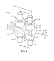
- FIG. 4 illustrates a perspective view of an embodiment of the mixing assembly 50.
- the mixing assembly 50 includes an integrated housing 150, or integrated valve assembly.
- the integrated housing 150 includes a top side 152, a bottom side 154, a front side 156, a back side 158, a left side 160, and a right side 162.
- the integrated housing 150 may be a generally rectangular shaped assembly. However, in other embodiments, the integrated housing 150 may have other shapes to accommodate the particular arrangement of the turbine fuel supply system 40.
- the integrated housing 150 may include a plurality of openings, or ports, to accommodate connections to equipment of the turbine fuel supply system 40.
- the actuators of the liquid fuel mixing valve 72 and the pilot fuel mixing valve 88 may be located on the top side 152.
- the actuators for the liquid fuel water mixing valve 76 and the pilot fuel water mixing valve 90 may be located on the bottom side 154.
- the actuators for the valves 72, 76, 88, and 90 may be oriented along multiple axes to reduce the space or volume taken up by the valves.
- the actuators for the various valves 72, 76, 88, and 90 may be located in different locations of the integrated housing 150.
- the valves 72, 76, 82, 88, 90, and 96 may be coupled directly to the integrated housing 150 and at least partially disposed in bores or openings drilled or formed in the integrated housing 150.
- the main fuel outlet port 126 may be located at the center of the liquid fuel proportioning valve 82
- the pilot fuel outlet port 128 may be located at the center of the pilot fuel pressurizing valve 96.
- the main fuel outlet port 126 and the pilot fuel outlet port 128 may be located in different locations of the integrated housing 150.
- the second pilot fuel outlet port 132 may be located on the front side 156 between the liquid fuel proportioning valve 82 and the pilot fuel pressurizing valve 96.
- the second pilot fuel outlet port 132 may be located in a different location of the integrated housing 150 or may be omitted.
- the valves 72, 76, 82, 88, 90, and 96 of the integrated housing 150 are proximate to one another.
- a distance 164 between centerlines of the valves 72 and 88 may be between approximately 30 to 80 percent, 40 to 70 percent, or 50 to 60 percent of a width 166 of the integrated housing 150.
- a distance 168 between centerlines of the valves 76 and 90 may be between approximately 30 to 80 percent, 40 to 70 percent, or 50 to 60 percent of the width 166 of the integrated housing 150.
- the distances 164 and/or 168 may be approximately 30, 40, 50, 60, 70, or 80 percent of the width 166.
- the valves 72 and 76 may be separated by a height 170 of the integrated housing 150.
- the valves 88 and 90 may be separated by the height 170 of the integrated housing 150.
- the integrated housing 150 may be compact with a reduced volume to reduce the amount of the liquid fuel 42 that may degrade inside the integrated housing 150.
- the length of passages between the valves 72, 76, 82, 88, 90, and 96 may be reduced to facilitate purging and cleaning of the integrated housing 150.
- FIG. 5 illustrates a rear view of an embodiment of the mixing assembly 50.
- the back side 158 includes main fuel inlet port 120, water inlet port 122, and pilot fuel inlet port 124.
- the main fuel inlet port 120 is located near the side 160 and adjacent to the liquid fuel mixing valve 72.
- the water inlet port 122 is located near the side 162 and adjacent to the pilot fuel water mixing valve 90.
- the pilot fuel inlet port 124 is located near the middle of the back side 158, or in between the main fuel inlet port 120 and the water inlet port 122.
- a diameter 121 of the main fuel inlet port 120 may be greater than a diameter 125 of the pilot fuel inlet port 124 because a flow rate of the liquid fuel 42 along path 44 may be greater than a flow rate of the pilot fuel along path 52.
- a ratio of the diameter 121 to the diameter 125 may be between approximately 1.1:1 to 6:1, 1.3:1 to 4:1, or 1.5:1 to 2.5:1.
- the ratio of the diameter 121 to the diameter 125 may be approximately 1.1, 1.3, 1.5, 2, 2.5, 3, 4, 5, or 6.
- the water inlet port 122 may be located near the middle of the back side 158, or in between the main fuel inlet port 120 and the pilot fuel inlet port 124.
- FIG. 6 illustrates a perspective view of an embodiment of various passages 180 within the integrated housing 150. Elements in FIG. 6 in common with those shown in FIGS. 4 and 5 are labeled with the same reference numerals. For clarity purposes, the valves 72, 76, 88, and 90 are not shown in FIG. 6 . Instead, circles are used in FIG. 6 to represent the locations of the valves 72, 76, 88, and 90. As shown in FIG. 6 , the liquid fuel passage 70 is routed directly from the main fuel inlet port 120 to the liquid fuel mixing valve 72. In other words, the liquid fuel passage 70 is routed to reduce the length of the passage 70.
- the water passage 74 is routed directly from the water inlet port 122 to the liquid fuel water mixing valve 76 and the pilot fuel water mixing valve 90.
- the pilot fuel passage 86 is routed directly from the pilot fuel inlet port 124 to the pilot fuel mixing valve 88.
- the passages 180 within the integrated housing 150 are routed in a direct manner to reduce the lengths of the passages 180, thereby reducing the inventory of material left in the passages 180 when not in use.
- the passages 180 may be formed by drilling holes or bores into a solid block of metal to produce a one-piece integrated housing 150. In other embodiments, holes or bores may be drilled into two or more blocks of metal that are then coupled together to form a multi-piece integrated housing 150.
- the passages 180 are completely integrated within the integrated housing 150.
- the lengths of the passages 180 may be less than lengths of external piping or tubing that is not within the integrated housing 150.
- the integrated housing 150 may be less cluttered and complicated than a network of external piping or tubing.
- the passages 180 may be formed in different directions depending on the particular arrangement of the integrated housing 150.
- cleaning and purging of the passages 180 within the integrated housing 150 is made easier and faster by reducing the lengths of the passages 180.
- forming the passages 180 out of a block of metal may reduce the possibility of leaks from the passages 180.
- the passages 180 in the integrated housing 150 also facilitate placement of the valves 72, 76, 82, 88, 90, and 96 in close proximity to one another.
- the passages 180 within the integrated housing 150 may have a circular cross-sectional shape and/or be internally smooth to help reduce locations where liquids may accumulate when not flowing through the passages 180.
- the passages 180 may have continuous downward slopes to help exclude liquid traps.
- the passages may be angled at an angle 181 with respect to a horizontal plane 183 containing the x-axis 144 and the y-axis 146.
- the angle 181 may be between approximately 1 to 45 degrees, 2 to 25 degrees, or 3 to 5 degrees.
- the angle 181 may be approximately 1, 2, 3, 5, 10, 15, 20, 25, 30, 35, 40, or 45 degrees.
- the passages 180 may have downward slopes that include downwardly sloping portions and horizontal portions, but not upwardly sloping portions.
- liquids may be able to drain freely out of the passages 180.
- additional drain lines or passages 182 may be coupled to ends and/or elbows of the passages 180 and to drain ports 184 to provide additional drainage capacity for the passages 180.
- the passages 180 exclude locations where liquids may be trapped within the integrated housing 150.
- various embodiments of the turbine fuel supply system 40 include the mixing assembly 50 to provide mixing of the liquid fuel 42 with the water 15 upstream of the combustor 16 to form the liquid fuel and pilot fuel mixtures 80 and 94.
- Such mixing of the water 15 with the liquid fuel 42 may help to reduce temperatures within the combustor 16 and help reduce formation of byproducts, such as NO x .
- Premixing of the water 15 and the liquid fuel 42 may also be more efficient at reducing NO x generation than injecting the water 15 into the combustor 16.
- the liquid fuel and pilot fuel mixtures 80 and 94 may have a lower viscosity and surface tension than the liquid fuel 42, thereby improving atomization, dispersion, and the evaporation rate of the mixtures 80 and 94 in the combustor 16.
- use of the mixing assembly 50 enables less water 15 to be used in reducing NO x generation because of the greater efficiency of NO x suppression provided by the mixtures 80 and 94.
- the arrangement of the valves 72, 76, 88, and 90 (and optionally valves 82 and 96) in close proximity to one another within the mixing assembly 50 may facilitate purging and cleanup of the turbine fuel supply system 40 when not using the liquid fuel 42.
- the configuration of the integrated housing 150 helps to reduce the amount of the liquid fuel 42 that is purged from the turbine fuel supply system 40, thereby improving the effectiveness of cleaning up any remaining liquid fuel 42.
- the passages 180 of the integrated housing 150 exclude liquid traps where the liquid fuel 42 may accumulate and degrade into deposits that may later interfere with operation of the combustor 16.
- use of the mixing assembly 50 may facilitate switching the combustor 16 to and from combustion of the liquid fuel 42.
Landscapes
- Engineering & Computer Science (AREA)
- Chemical & Material Sciences (AREA)
- Combustion & Propulsion (AREA)
- Mechanical Engineering (AREA)
- General Engineering & Computer Science (AREA)
- Feeding And Controlling Fuel (AREA)
Abstract
Description
- The subject matter disclosed herein relates to combustion systems, and, more particularly, to supplying liquid fuel mixtures to gas turbine engines.
- Various combustion systems include combustion chambers in which fuel and air combust to generate hot gases. For example, a gas turbine engine may include one or more combustion chambers that are configured to receive compressed air from a compressor, inject fuel into the compressed air, and generate hot combustion gases to drive the turbine engine. Each combustion chamber may be configured to receive one or more different fuels, such as gaseous fuels and liquid fuels. Certain materials may be mixed with the fuel to affect combustion efficiency and/or production of byproducts, for example. Unfortunately, such mixtures left in an unused flow path may degrade, thereby decreasing performance and reliability of the gas turbine engine.
- Certain embodiments commensurate in scope with the originally claimed invention are summarized below. These embodiments are not intended to limit the scope of the claimed invention, but rather these embodiments are intended only to provide a brief summary of possible forms of the invention. Indeed, the invention may encompass a variety of forms that may be similar to or different from the embodiments set forth below.
- In a first aspect, the invention resides in a system including a mixing assembly configured to mix a liquid fuel and a water to generate a fuel mixture. The fuel mixture is configured to combust in a combustor of a gas turbine. The mixing assembly includes a liquid fuel passage disposed in an integrated housing. The liquid fuel passage is configured to flow the liquid fuel and to exclude liquid traps. The mixing assembly also includes a water passage disposed in the integrated housing. The water passage is configured to flow the water and to exclude liquid traps. The mixing assembly also includes a mixer disposed in the integrated housing and coupled to the liquid fuel passage and the water passage. The mixer is configured to mix the liquid fuel and the water to form the fuel mixture.
- In a second aspect, the invention resides in a system including a valve assembly configured to mix a liquid fuel and a water to generate a fuel mixture. The fuel mixture is configured to combust in a combustor of a gas turbine. The valve assembly includes an integrated housing, a liquid fuel valve directly coupled to the integrated housing and configured to adjust a flow rate of the liquid fuel, and a water valve directly coupled to the integrated housing and configured to adjust a flow rate of the water. The liquid fuel valve and the water valve are proximate to one another. The valve assembly also includes liquid fuel valve and the water valve are proximate to one another. The passage is configured to exclude liquid traps. The system also includes a controller configured to transmit a signal to at least one of the liquid fuel valve and the water valve. The liquid fuel valve and the water valve are responsive to the signal, to adjust a composition of the fuel mixture.
- In a third aspect, the invention resides in a system includes an integrated valve assembly. The integrated valve assembly includes a main fuel inlet port configured to receive a main fuel, a main fuel passage coupled to the main fuel inlet port and configured to route the main fuel to a first mixing tee, a main fuel valve coupled to the main fuel passage and configured to adjust a main flow rate of the main fuel, a water inlet port configured to receive water, and a water passage coupled to the water inlet port and configured to route the water to the first mixing tee. The main fuel passage and the water passage are configured to exclude liquid traps, and the first mixing tee is configured to generate a main fuel mixture. The integrated valve assembly also includes a main fuel mixture outlet port configured to discharge the main fuel mixture and a first water valve coupled to the water passage and configured to adjust a first water flow rate of the water. The main fuel valve and the first water valve are proximate to one another.
- Embodiments of the present invention will now be described, by way of example only, with reference to the accompanying drawings in which:
-
FIG. 1 is a block diagram of an embodiment of a turbine system having a combustor; -
FIG. 2 is a block diagram of an embodiment of a fuel supply system for a turbine combustor; -
FIG. 3 is a block diagram of an embodiment of a fuel supply system for a turbine combustor; -
FIG. 4 is a perspective view of an embodiment of an integrated valve assembly; -
FIG. 5 is a rear view of an embodiment of an integrated valve assembly; and -
FIG. 6 is a front perspective view of an embodiment of a manifold of an integrated valve assembly. - One or more specific embodiments of the present invention will be described below. In an effort to provide a concise description of these embodiments, all features of an actual implementation may not be described in the specification. It should be appreciated that in the development of any such actual implementation, as in any engineering or design project, numerous implementation-specific decisions must be made to achieve the developers' specific goals, such as compliance with system-related and business-related constraints, which may vary from one implementation to another. Moreover, it should be appreciated that such a development effort might be complex and time consuming, but would nevertheless be a routine undertaking of design, fabrication, and manufacture for those of ordinary skill having the benefit of this disclosure.
- When introducing elements of various embodiments of the present invention, the articles "a," "an," "the," and "said" are intended to mean that there are one or more of the elements. The terms "comprising," "including," and "having" are intended to be inclusive and mean that there may be additional elements other than the listed elements.
- As discussed in detail below, certain embodiments provide systems for mixing a fuel with water and supplying the mixture of fuel and water to a turbine combustor. For example, the turbine combustor may be a gas turbine combustor disposed in a gas turbine engine. In certain embodiments, the gas turbine combustor may combust either a gaseous fuel, such as natural gas, syngas, or substitute natural gas, or a liquid fuel, such as diesel fuel. The gaseous fuel may be supplied to the gas turbine combustor via a gaseous fuel path and the liquid fuel may be supplied via a liquid fuel flow path separate from the gaseous flow path. The gas turbine combustor may primarily combust the gaseous fuel and, when the gaseous fuel is unavailable, combust the liquid fuel. Thus, even if a supply of gaseous fuel is interrupted, operation of the turbine combustor may continue by using the liquid fuel. However, use of gaseous fuel may be preferable because combustion of the liquid fuel may be less efficient than combustion of the gaseous fuel, and because combustion of the liquid fuel may generate more byproducts in an exhaust from the gas turbine engine than combustion of the gaseous fuel. These byproducts may include nitrogen oxides (NOx), sulfur oxides (SOx), carbon monoxide (CO), particulate matter, and so forth.
- When liquid fuel is used in the gas turbine combustor, water may be mixed with the liquid fuel prior to introduction into the gas turbine combustor to help reduce byproduct (e.g., NOx, SOx, CO, or particulate matter) production. The added water may aid in cooling the reaction zone in the gas turbine combustor, which may reduce byproduct production. Specifically, the water vaporizes into steam in the reaction zone, which helps to reduce the temperature of the reaction zone. In certain embodiments, a mixing assembly may mix the water and liquid fuel to generate a fuel mixture. The mixing assembly may be an integrated housing that includes a plurality of components. For example, the integrated housing may include a liquid fuel passage that flows the liquid fuel through the integrated housing. Similarly, the integrated housing may include a water passage that flows the water through the integrated housing. Both the liquid fuel passage and the water passage may exclude liquid traps, which may be defined as areas in which liquids may accumulate when not flowing through the integrated housing. Thus, excluding liquid traps may refer to substantially reducing or eliminating regions that liquids may accumulate and cannot be removed or drained. One manner to exclude liquid traps in the integrated housing may include utilizing downward slopes in the passages, such that the liquid fuel and/or the water may drain out of the integrated housing without being trapped within the integrated housing. In certain embodiments, the downward slopes may be continuous downward slopes, with no horizontal or upward portions. In other embodiments, the downward slopes may include downward portions and horizontal portions, but no upward portions. By excluding liquids traps, the integrated housing helps to prevent stagnant liquid fuel from degrading and potentially forming a coking buildup in the flow path within the integrated housing. The coking buildup may cause changes in system flow characteristics, thereby causing the gas turbine combustor to operate inefficiently. The coking buildup could also partially block downstream fuel nozzles. In further embodiments, the mixing assembly may include a mixer disposed in the integrated housing and coupled to the liquid fuel passage and the water passage. The mixer may mix the liquid fuel and the water to form the fuel mixture. The mixer may improve the uniformity of the fuel mixture. Inadequately mixed fuel mixtures may cause uneven combustion within the gas turbine combustor.
- In other embodiments, the integrated housing may include the fuel flow path, a water flow path, and/or a path for a mixture of both fuel and water. By excluding liquid fuel traps, the internal surfaces of the flow paths may be generally smooth to enable fluid flow free of bumps, sharp corners, recesses, steps, sharp diameter changes, and so forth. Thus, any remaining fuel may be carried away by water flow through the fuel passages to help prevent any coking buildup.
- In further embodiments, the integrated housing may include additional components to help generate a uniform fuel mixture. For example, the liquid fuel passage may include a liquid fuel valve that adjusts a flow rate of the liquid fuel. Similarly, the water passage may include a water valve that adjusts a flow rate of the water. In certain embodiments, the liquid fuel valve and the water valve are proximate to one another. Thus, lengths of the passages within the integrated housing may be reduced to facilitate purging and cleanup of the integrated housing. In further embodiments, a controller may transmit a signal to the liquid fuel valve and/or the water valve to adjust a composition of the fuel mixture. The signal may be mechanical or electrical. In certain embodiments, water from the water valve may flow backward through the liquid fuel valve and the liquid fuel passage to help clean or purge any remaining oil left in the liquid fuel valve and liquid fuel passage.
- Turning now to the drawings and referring first to
FIG. 1 , a block diagram of an embodiment of aturbine system 10 having agas turbine engine 11 is illustrated. Theturbine system 10 may use liquid or gaseous fuel, such as natural gas and/or a synthetic gas, to drive theturbine system 10. As depicted, one ormore fuel nozzles 12 intake afuel supply 14. For example, one ormore fuel nozzles 12 may be used to intake liquid fuel, and one or moreother fuel nozzles 12 may be used to intake gaseous fuel. In addition, thefuel nozzles 12 may intake awater supply 15 when theturbine system 10 uses liquid fuel. As described in detail below, the disclosedturbine system 10 mixes the liquid fuel with thewater supply 15 upstream from and/or within thefuel nozzles 12. Mixing the liquid fuel with thewater 15 may improve the efficiency of byproduct (e.g., NOx, SOx, CO, or particulate matter) suppression, thereby reducing production and exhaust of the byproducts from thegas turbine engine 11. The fuel nozzles 12 then further mix the fuel, or the fuel-water mixture, with air, and distribute the fuel, water (when used), and air mixture into thecombustor 16 where further mixing occurs between the fuel, water (when used), and air. Although shown schematically as being outside or separate from thecombustor 16, thefuel nozzles 12 may be disposed inside thecombustor 16. The fuel, water (when used), and air mixture combusts in a chamber within thecombustor 16, thereby creating hot pressurized exhaust gases. Thecombustor 16 directs the exhaust gases through aturbine 18 toward anexhaust outlet 20. Although only onecombustor 16 is shown inFIG. 1 , in certain embodiments, a plurality ofcombustors 16 may be arranged circumferentially about thegas turbine engine 11. Each of the plurality ofcombustors 16 may includeseparate fuel nozzles 12. As the exhaust gases pass through theturbine 18, the gases force turbine blades to rotate ashaft 22 along an axis of theturbine system 10. As illustrated, theshaft 22 is connected to various components of theturbine system 10, including acompressor 24. Thecompressor 24 also includes blades coupled to theshaft 22. As theshaft 22 rotates, the blades within thecompressor 24 also rotate, thereby compressing air from anair intake 26 through thecompressor 24 and into thefuel nozzles 12 and/orcombustor 16. Theshaft 22 may also be connected to aload 28, which may be a vehicle or a stationary load, such as an electrical generator in a power plant or a propeller on an aircraft, for example. Theload 28 may include any suitable device capable of being powered by the rotational output ofturbine system 10. -
FIG. 2 illustrates a block diagram of a turbinefuel supply system 40 of thecombustor 16 of thegas turbine engine 11, as illustrated inFIG. 1 . In the following discussion, the term "valve" is used to refer to any device capable of operating as a flow control. As illustrated, aliquid fuel 42 may be supplied to thecombustor 16. Examples of theliquid fuel 42 include, but are not limited to, hydrocarbon based liquid fuels, such as diesel fuel, jet fuel, gasoline, naphtha, fuel oil, and so forth. Theliquid fuel 42 is routed to thecombustor 16 via a liquid fuel flow path 44, which may include a liquidfuel supply valve 46. The liquid fuel flow path 44 may also include aliquid fuel manifold 48, which may be used to supply theliquid fuel 42 to a plurality of mixing assemblies 50 (as indicated by vertical dots), which may be, for example, arranged circumferentially about theliquid fuel manifold 48. In certain embodiments, theliquid fuel manifold 48 may be configured as a ring with a circular or polygonal shape. Each of the plurality of mixingassemblies 50 may be coupled to one of the plurality ofcombustors 16 arranged circumferentially about thegas turbine engine 11. The liquidfuel supply valve 46 may be used to adjust and/or isolate flow of theliquid fuel 42 to theliquid fuel manifold 48. In certain embodiments, each mixingassembly 50 may include a plurality of valves and passages, as discussed in detail below, to mix theliquid fuel 42 with thewater 15. - In certain embodiments, a portion of the
liquid fuel 42 may be routed to a pilotfuel flow path 52, which may include a pilotfuel supply valve 54. The pilotfuel flow path 52 may be used when first starting thecombustor 16 with theliquid fuel 42. For example, the pilotfuel flow path 52 may flow a lower flow rate of theliquid fuel 42 than the liquid fuel flow path 44. In certain embodiments, the flow rate of theliquid fuel 42 through the pilotfuel flow path 52 may be between approximately 5 percent to 50 percent, 10 percent to 35 percent, or 15 percent to 25 percent of a normal, or regular, flow rate through the liquid fuel flow path 44. For example, the flow rate of theliquid fuel 42 through the pilotfuel flow path 52 may be approximately 5, 10, 15, 20, 25, 30, 35, 40, 45, or 50 percent of the normal flow rate through the liquid fuel flow path 44. A low flow rate of theliquid fuel 42, which may be referred to as pilot fuel, may be used to first start thecombustor 16. Afterwards, the liquid fuel flow path 44 may be used to supply the normal, or regular, flow rate of theliquid fuel 42 to thecombustor 16. The pilotfuel flow path 52 may also continue to be used together with the liquid fuel flow path 44 for reasons discussed in detail below. During startup of thecombustor 16, theliquid fuel 42 from the pilotfuel supply valve 54 may be routed to apilot fuel manifold 58, which may be used to supply pilot fuel to the plurality of mixing assemblies 50 (as indicated by vertical dots). In certain embodiments, thepilot fuel manifold 58 may be configured as a ring with a circular or polygonal shape. The pilotfuel supply valve 54 may be used to adjust and/or isolate flow of theliquid fuel 42 to thepilot fuel manifold 58. When thecombustor 16 is no longer combusting theliquid fuel 42, agaseous fuel 60 may be supplied to thepilot fuel manifold 58 via a gaseousfuel flow path 61, thereby purging theliquid fuel 42 from thepilot fuel manifold 58 with thegaseous fuel 60. Examples of thegaseous fuel 60 include, but are not limited to, methane, natural gas, syngas, and so forth. The gaseousfuel flow path 61 may include a gaseous fuel supply valve 62, which may be used to adjust and/or isolate flow of thegaseous fuel 60. Purging the pilotfuel flow path 52 with thegaseous fuel 60 may help to substantially reduce or prevent coking or oxidizing of theliquid fuel 42 in the pilotfuel flow path 52 when not in use. In other embodiments, other gases, such as nitrogen, carbon dioxide, steam, and so forth, may be used to purge the pilotfuel flow path 52 when not in use. - The
water 15 may be supplied to thecombustor 16 via awater flow path 64, which may include awater supply valve 66. Examples of thewater 15 include, but are not limited to, boiler feedwater, deaerated water, steam condensate, demineralized water, and so forth.Such water 15 may already be available elsewhere in the plant or facility where thegas turbine engine 11 is located. Thus, the water supply system for the turbinefuel supply system 40 may not include a separate, dedicated water supply system. Thewater supply valve 66 may be used to adjust and/or isolate a flow of thewater 15 to awater manifold 68, which may be used to supply thewater 15 to the plurality of mixing assemblies 50 (as indicated by vertical dots). In certain embodiments, thewater manifold 68 may be configured as a ring with a circular or polygonal shape. - Each of the plurality of mixing
assemblies 50 may include a variety of components to help produce uniform mixtures of theliquid fuel 42 and thewater 15. For example, each mixingassembly 50 may include aliquid fuel passage 70 that flows theliquid fuel 42 to a liquidfuel mixing valve 72, which may be used to adjust a flow rate of theliquid fuel 42 through the mixingassembly 50. For example, the liquidfuel mixing valve 72 may be an on/off valve or a throttling valve. Similarly, the mixingassembly 50 may include awater passage 74 that flows thewater 15 into the mixingassembly 50. Thewater passage 74 may include a liquid fuelwater mixing valve 76, which may be used to adjust a flow rate of thewater 15 to be mixed with theliquid fuel 42 flowing through theliquid fuel passage 70. For example, the liquid fuelwater mixing valve 76 may be an on/off valve or a throttling valve. Theliquid fuel 42 and thewater 15 combine at amixer 78 that mixes theliquid fuel 42 and thewater 15 to form aliquid fuel mixture 80. In certain embodiments, theliquid fuel mixture 80 may be an emulsion of theliquid fuel 42 and thewater 15. Examples of themixer 78 include, but are not limited to, a mixing tee, an inline mixer, a static mixer, a paddle mixer, a blender, a ribbon blender, and so forth. Themixer 78 generates a uniform mixture of theliquid fuel 42 and thewater 15. When thegas turbine engine 11 is not combusting the liquid fuel 42 (e.g., combusting the gaseous fuel 60), thewater 15 may be used to purge theliquid fuel passage 70. Specifically, thewater 15 may flow backward through the liquidfuel mixing valve 72 and into theliquid fuel manifold 48, purging or displacing theliquid fuel 42. In certain embodiments, the mixingassembly 50 may include a liquidfuel proportioning valve 82 disposed downstream of themixer 78. The liquidfuel proportioning valve 82 may enable the flow of theliquid fuel mixture 80 along a mainfuel flow path 83 to all of thecombustors 16 of thegas turbine engine 11 if a pressure of theliquid fuel mixture 80 is above a threshold pressure. For example, the liquidfuel proportioning valve 82 may be a control valve, pressure valve, one-way valve, check valve, or any combination thereof. Thus, the liquidfuel proportioning valve 82 may help prevent backflow of gases from thecombustor 16 into the mixingassembly 50. In other words, the liquidfuel proportioning valve 82 may enable flow of theliquid fuel mixture 80 into thecombustor 16 only when the pressure of theliquid fuel mixture 80 exceeds a preset pressure. Theliquid fuel mixture 80 from the mixingassembly 50 may then be routed tomain nozzles 84 of thecombustor 16 along the mainfuel flow path 83. - In certain embodiments, the mixing
assembly 50 may include apilot fuel passage 86 that routes the pilot fuel to a pilotfuel mixing valve 88, which may be used to adjust a flow rate of the pilot fuel to the mixingassembly 50. For example, the pilotfuel mixing valve 88 may be an on/off valve or a throttling valve. Thewater passage 74 may include a pilot fuelwater mixing valve 90 that flows thewater 15 to apilot fuel mixer 92, which may mix the pilot fuel and thewater 15 to form apilot fuel mixture 94. In certain embodiments, thepilot fuel mixture 94 may be an emulsion of the pilot fuel and thewater 15. For example, the pilot fuelwater mixing valve 90 may be an on/off valve or a throttling valve. Examples of thepilot fuel mixer 92 include, but are not limited to, a mixing tee, an inline mixer, a static mixer, a paddle mixer, a blender, a ribbon blender, and so forth. When thegas turbine engine 11 is not combusting the liquid fuel 42 (e.g., combusting the gaseous fuel 60), thewater 15 may be used to purge thepilot fuel passage 86. Specifically, thewater 15 may flow backward through the pilotfuel mixing valve 88 and into thepilot fuel manifold 58, purging or displacing theliquid fuel 42. In some embodiments, thepilot fuel mixture 94 may be routed to a pilotfuel pressurizing valve 96, which may enable flow of thepilot fuel mixture 94 along a first pilotfuel flow path 97 if a pressure of thepilot fuel mixture 94 is above a threshold pressure. For example, the pilotfuel pressurizing valve 96 may be a control valve, pressure valve, one-way valve, check valve, or any combination thereof. Thus, the pilotfuel pressurizing valve 96 may help to prevent backflow of gases from thecombustor 16 into the mixingassembly 50. Thepilot fuel mixture 94 from the pilotfuel pressurizing valve 96 may then be routed to pilotnozzles 98 of thecombustor 16 along the first pilotfuel flow path 97. The pilot nozzles 98 may be smaller than themain nozzles 84 to enable thepilot nozzles 98 to inject theliquid fuel 42 into thecombustor 16 at a lower flow rate than themain nozzles 84, but with enough nozzle pressure drop to generate an ignitable spray of liquid fuel. The pilot nozzles 98 may be continuously purged with thegaseous fuel 60 when thecombustor 16 is not combusting theliquid fuel 42 to help block hot combustion products (e.g., air, carbon dioxide, water vapor, and so forth) from entering and degrading the small orifices of thepilot nozzles 98. When thecombustor 16 is combusting theliquid fuel 42, thepilot nozzles 98 may inject theliquid fuel 42 concurrently with themain nozzles 84 as thepilot nozzles 98 may be cooled by the flow of thepilot fuel mixture 94 through thepilot nozzles 98. - In certain embodiments, the turbine
fuel supply system 40 may include acontroller 100, which may send and/or receive various signals alongsignal paths 102. In the following discussion, the signals sent or received along thesignal paths 102 will also be referred to by thereference numeral 102. For example, thecontroller 100 may sendsignals 102 to one or more of the liquidfuel supply valve 46, the pilotfuel supply valve 54, the gaseous fuel supply valve 62, thewater supply valve 66, the liquidfuel mixing valve 72, the liquid fuelwater mixing valve 76, the liquidfuel proportioning valve 82, the pilotfuel mixing valve 88, the pilotfuel water valve 90, and the pilotfuel pressurizing valve 96 to direct the valves to open or close. In addition, thecontroller 100 may receivesignals 102 fromsensors 104 disposed in the turbinefuel supply system 40, such as, but not limited to, pressure sensors, temperature sensors, flow rate sensors, composition sensors, and so forth. In certain embodiments, thecontroller 100 may adjust a ratio of theliquid fuel 42 to thewater 15 based on thesignals 102 received from thesensors 104. -
FIG. 3 illustrates a block diagram of another embodiment of the turbinefuel supply system 40. As shown inFIG. 3 , the mixingassembly 50 includes a mainfuel inlet port 120 that receives theliquid fuel 42. The mainfuel inlet port 120 is coupled to themain fuel passage 70. In addition, the mixingassembly 50 includes awater inlet port 122 that receives thewater 15. Thewater inlet port 122 is coupled to thewater passage 74. Further, the mixingassembly 50 includes a pilotfuel inlet port 124 that receives the pilot fuel. The pilotfuel inlet port 124 is coupled to thepilot fuel passage 86. The mixingassembly 50 may also include a main fuelmixture outlet port 126 that discharges theliquid fuel mixture 80 to themain nozzles 84. Similarly, the mixingassembly 50 may include a pilot fuelmixture outlet port 128 that discharges the pilot fuel mixture to thepilot nozzles 98 along the first pilotfuel flow path 97. In certain embodiments, aportion 130 of thepilot fuel mixture 94 may be supplied directly to a second pilotfuel outlet port 132. In other words, theportion 130 of thepilot fuel mixture 94 does not flow through the pilotfuel pressurizing valve 96. Instead, theportion 130 of thepilot fuel mixture 94 flows along a second pilotfuel flow path 133 to asecond set 134 of pilot nozzles of thecombustor 16. The pressurizingvalve 96 is used to flow thepilot fuel mixture 94 when the pressure threshold of themixture 94 is reached. In other words, the function of the pressurizingvalve 96 is to sequentially wet thepilot nozzles -
FIG. 4 illustrates a perspective view of an embodiment of the mixingassembly 50. In the following discussion, reference may be made to anx-axis 144, a y-axis 146, and a z-axis 148. As shown inFIG. 4 , the mixingassembly 50 includes anintegrated housing 150, or integrated valve assembly. Theintegrated housing 150 includes atop side 152, abottom side 154, afront side 156, aback side 158, aleft side 160, and aright side 162. As shown inFIG. 4 , theintegrated housing 150 may be a generally rectangular shaped assembly. However, in other embodiments, theintegrated housing 150 may have other shapes to accommodate the particular arrangement of the turbinefuel supply system 40. In addition, theintegrated housing 150 may include a plurality of openings, or ports, to accommodate connections to equipment of the turbinefuel supply system 40. Further, the actuators of the liquidfuel mixing valve 72 and the pilotfuel mixing valve 88 may be located on thetop side 152. Similarly, the actuators for the liquid fuelwater mixing valve 76 and the pilot fuelwater mixing valve 90 may be located on thebottom side 154. Thus, the actuators for thevalves various valves integrated housing 150. Thevalves integrated housing 150 and at least partially disposed in bores or openings drilled or formed in theintegrated housing 150. In addition, the mainfuel outlet port 126 may be located at the center of the liquidfuel proportioning valve 82, and the pilotfuel outlet port 128 may be located at the center of the pilotfuel pressurizing valve 96. In other embodiments, the mainfuel outlet port 126 and the pilotfuel outlet port 128 may be located in different locations of theintegrated housing 150. The second pilotfuel outlet port 132 may be located on thefront side 156 between the liquidfuel proportioning valve 82 and the pilotfuel pressurizing valve 96. In other embodiments, the second pilotfuel outlet port 132 may be located in a different location of theintegrated housing 150 or may be omitted. As shown inFIG. 4 , thevalves integrated housing 150 are proximate to one another. For example, adistance 164 between centerlines of thevalves width 166 of theintegrated housing 150. Similarly, adistance 168 between centerlines of thevalves width 166 of theintegrated housing 150. Thus, thedistances 164 and/or 168 may be approximately 30, 40, 50, 60, 70, or 80 percent of thewidth 166. Further, thevalves height 170 of theintegrated housing 150. Similarly, thevalves height 170 of theintegrated housing 150. Thus, theintegrated housing 150 may be compact with a reduced volume to reduce the amount of theliquid fuel 42 that may degrade inside theintegrated housing 150. Further, the length of passages between thevalves integrated housing 150. -
FIG. 5 illustrates a rear view of an embodiment of the mixingassembly 50. As shown inFIG. 5 , theback side 158 includes mainfuel inlet port 120,water inlet port 122, and pilotfuel inlet port 124. In certain embodiments, the mainfuel inlet port 120 is located near theside 160 and adjacent to the liquidfuel mixing valve 72. In certain embodiments, thewater inlet port 122 is located near theside 162 and adjacent to the pilot fuelwater mixing valve 90. In some embodiments, the pilotfuel inlet port 124 is located near the middle of theback side 158, or in between the mainfuel inlet port 120 and thewater inlet port 122. In certain embodiments, adiameter 121 of the mainfuel inlet port 120 may be greater than adiameter 125 of the pilotfuel inlet port 124 because a flow rate of theliquid fuel 42 along path 44 may be greater than a flow rate of the pilot fuel alongpath 52. For example, a ratio of thediameter 121 to thediameter 125 may be between approximately 1.1:1 to 6:1, 1.3:1 to 4:1, or 1.5:1 to 2.5:1. In certain embodiments, the ratio of thediameter 121 to thediameter 125 may be approximately 1.1, 1.3, 1.5, 2, 2.5, 3, 4, 5, or 6. In another embodiment, thewater inlet port 122 may be located near the middle of theback side 158, or in between the mainfuel inlet port 120 and the pilotfuel inlet port 124. -
FIG. 6 illustrates a perspective view of an embodiment ofvarious passages 180 within theintegrated housing 150. Elements inFIG. 6 in common with those shown inFIGS. 4 and5 are labeled with the same reference numerals. For clarity purposes, thevalves FIG. 6 . Instead, circles are used inFIG. 6 to represent the locations of thevalves FIG. 6 , theliquid fuel passage 70 is routed directly from the mainfuel inlet port 120 to the liquidfuel mixing valve 72. In other words, theliquid fuel passage 70 is routed to reduce the length of thepassage 70. Similarly, thewater passage 74 is routed directly from thewater inlet port 122 to the liquid fuelwater mixing valve 76 and the pilot fuelwater mixing valve 90. Thepilot fuel passage 86 is routed directly from the pilotfuel inlet port 124 to the pilotfuel mixing valve 88. Thus, thepassages 180 within theintegrated housing 150 are routed in a direct manner to reduce the lengths of thepassages 180, thereby reducing the inventory of material left in thepassages 180 when not in use. For example, thepassages 180 may be formed by drilling holes or bores into a solid block of metal to produce a one-pieceintegrated housing 150. In other embodiments, holes or bores may be drilled into two or more blocks of metal that are then coupled together to form a multi-pieceintegrated housing 150. In other words, thepassages 180 are completely integrated within theintegrated housing 150. In addition, the lengths of thepassages 180 may be less than lengths of external piping or tubing that is not within theintegrated housing 150. Further, theintegrated housing 150 may be less cluttered and complicated than a network of external piping or tubing. Thepassages 180 may be formed in different directions depending on the particular arrangement of theintegrated housing 150. In addition, cleaning and purging of thepassages 180 within theintegrated housing 150 is made easier and faster by reducing the lengths of thepassages 180. Further, forming thepassages 180 out of a block of metal may reduce the possibility of leaks from thepassages 180. In other words, using theintegrated housing 150 avoids the joints, flanges, fittings, connections, and so forth associated with external piping and tubing. Thepassages 180 in theintegrated housing 150 also facilitate placement of thevalves passages 180 within theintegrated housing 150 may have a circular cross-sectional shape and/or be internally smooth to help reduce locations where liquids may accumulate when not flowing through thepassages 180. - Low spots and other locations where liquids may accumulate are referred to as liquid traps. In certain embodiments, the
passages 180 may have continuous downward slopes to help exclude liquid traps. In other words, the passages may be angled at anangle 181 with respect to ahorizontal plane 183 containing thex-axis 144 and the y-axis 146. In certain embodiments, theangle 181 may be between approximately 1 to 45 degrees, 2 to 25 degrees, or 3 to 5 degrees. For example, theangle 181 may be approximately 1, 2, 3, 5, 10, 15, 20, 25, 30, 35, 40, or 45 degrees. In other embodiments, thepassages 180 may have downward slopes that include downwardly sloping portions and horizontal portions, but not upwardly sloping portions. Thus, liquids may be able to drain freely out of thepassages 180. In certain embodiments, additional drain lines orpassages 182 may be coupled to ends and/or elbows of thepassages 180 and to drainports 184 to provide additional drainage capacity for thepassages 180. Thus, thepassages 180 exclude locations where liquids may be trapped within theintegrated housing 150. - As discussed above, various embodiments of the turbine
fuel supply system 40 include the mixingassembly 50 to provide mixing of theliquid fuel 42 with thewater 15 upstream of thecombustor 16 to form the liquid fuel andpilot fuel mixtures water 15 with theliquid fuel 42 may help to reduce temperatures within thecombustor 16 and help reduce formation of byproducts, such as NOx. Premixing of thewater 15 and theliquid fuel 42 may also be more efficient at reducing NOx generation than injecting thewater 15 into thecombustor 16. For example, the liquid fuel andpilot fuel mixtures liquid fuel 42, thereby improving atomization, dispersion, and the evaporation rate of themixtures combustor 16. Thus, use of the mixingassembly 50 enablesless water 15 to be used in reducing NOx generation because of the greater efficiency of NOx suppression provided by themixtures valves optionally valves 82 and 96) in close proximity to one another within the mixingassembly 50 may facilitate purging and cleanup of the turbinefuel supply system 40 when not using theliquid fuel 42. Specifically, the configuration of theintegrated housing 150 helps to reduce the amount of theliquid fuel 42 that is purged from the turbinefuel supply system 40, thereby improving the effectiveness of cleaning up any remainingliquid fuel 42. For example, thepassages 180 of theintegrated housing 150 exclude liquid traps where theliquid fuel 42 may accumulate and degrade into deposits that may later interfere with operation of thecombustor 16. Thus, use of the mixingassembly 50 may facilitate switching thecombustor 16 to and from combustion of theliquid fuel 42. - This written description uses examples to disclose the invention, including the best mode, and also to enable any person skilled in the art to practice the invention, including making and using any devices or systems and performing any incorporated methods. The patentable scope of the invention is defined by the claims, and may include other examples that occur to those skilled in the art. Such other examples are intended to be within the scope of the claims if they have structural elements that do not differ from the literal language of the claims, or if they include equivalent structural elements with insubstantial differences from the literal language of the claims.
- Various aspects and embodiments of the present invention are defined by the following numbered clauses:
- 1. A system, comprising:
- a valve assembly configured to mix a liquid fuel and a water to generate a fuel mixture, wherein the fuel mixture is configured to combust in a combustor of a gas turbine, and the valve assembly comprises:
- an integrated housing;
- a liquid fuel valve directly coupled to the integrated housing and configured to adjust a flow rate of the liquid fuel;
- a water valve directly coupled to the integrated housing and configured to adjust a flow rate of the water, wherein the liquid fuel valve and the water valve are proximate to one another; and
- a passage disposed in the integrated housing and configured to mix the liquid fuel and the water to form the fuel mixture, wherein the passage is configured to exclude liquid traps; and
a controller configured to transmit a signal to at least one of the liquid fuel valve or the water valve, wherein the liquid fuel valve or the water valve is responsive to the signal to adjust a composition of the fuel mixture.
- a valve assembly configured to mix a liquid fuel and a water to generate a fuel mixture, wherein the fuel mixture is configured to combust in a combustor of a gas turbine, and the valve assembly comprises:
- 2. The system of
clause 1, wherein the water valve is configured to flow water through the liquid fuel valve and the passage to purge the liquid fuel from the valve assembly when the fuel mixture is not being combusted in the combustor. - 3. The system of
clause - 4. The system of
clause - 5. The system of any of
clauses 1 to 4, wherein the valve assembly comprises a pressurizing valve directly coupled to the integrated housing and the pressurizing valve is configured to enable flow of the fuel mixture to the gas turbine combustor if a pressure of the fuel mixture is above a threshold pressure of the fuel mixture. - 6. A system, comprising:
- an integrated valve assembly, comprising:
- a main fuel inlet port configured to receive a main fuel;
- a main fuel passage coupled to the main fuel inlet port and configured to route the main fuel to a first mixing tee;
a main fuel valve coupled to the main fuel passage and configured to adjust a main flow rate of the main fuel; - a water inlet port configured to receive water;
- a water passage coupled to the water inlet port and configured to route the water to the first mixing tee, wherein the main fuel passage and the water passage are configured to exclude liquid traps, and the first mixing tee is configured to mix the main fuel and the water to generate a main fuel mixture;
- a main fuel mixture outlet port configured to discharge the main fuel mixture;
and - a first water valve coupled to the water passage and configured to adjust a first water flow rate of the water, wherein the main fuel valve and the first water valve are proximate to one another.
- an integrated valve assembly, comprising:
- 7. The system of clause 6, wherein the integrated valve assembly comprises:
- a pilot fuel inlet port configured to receive a pilot fuel;
- a pilot fuel passage coupled to the pilot fuel inlet port and configured to route the pilot fuel to a second mixing tee;
a pilot fuel valve coupled to the pilot fuel passage and configured to adjust a pilot flow rate of the pilot fuel;
a second water passage coupled to the water inlet port and configured to route the water to the second mixing tee, wherein the second water passage is configured to exclude liquid traps, and the second mixing tee is configured to mix the pilot fuel and the water to generate a pilot fuel mixture;
a pilot fuel mixture outlet port configure to discharge the pilot fuel mixture; - and
a second water valve coupled to the second water passage and configured to adjust a second water flow rate of the water to the second mixing tee, wherein the pilot fuel valve and the second water valve are proximate to one another.
- 8. The system of clause 7, wherein the pilot fuel and the main fuel comprise liquid fuels.
- 9. The system of clause 7 or 8, wherein a first diameter of the main fuel inlet port is greater than a second diameter of the pilot fuel inlet port.
- 10. The system of any of clauses 6 to 9, wherein the main fuel inlet port and water inlet port are disposed on a first side of the integrated valve assembly, the main fuel mixture outlet port is disposed on a second side of the integrated valve assembly, and the first and second sides of the integrated valve assembly are located opposite from one another.
- 11. The system of any of clauses 6 to 10, wherein the integrated valve assembly comprises a proportioning valve coupled to the main fuel mixture outlet port, the proportioning valve is configured to enable flow of the main fuel mixture if a pressure of the main fuel mixture is above a threshold pressure of the main fuel mixture.
- 12. The system of any of clauses 6 to 11, wherein the first water valve is configured to flow water through the main fuel valve and the main fuel passage to purge the main fuel from the integrated valve assembly when the main fuel mixture is not being used.
Claims (8)
- A system, comprising:a mixing assembly (50) configured to mix a liquid fuel (42) and a water (15) to generate a fuel mixture (80), wherein the fuel mixture (80) is configured to combust in a combustor (16) of a gas turbine (11), and the mixing assembly (50) comprises:a liquid fuel passage (70) disposed in an integrated housing (150), wherein the liquid fuel passage (70) is configured to flow the liquid fuel (42) and to exclude liquid traps;a water passage (74) disposed in the integrated housing (150), wherein the water passage (74) is configured to flow the water (15) and to exclude liquid traps; anda mixer (78) disposed in the integrated housing (150) and coupled to the liquid fuel passage (70) and the water passage (74), wherein the mixer (78) is configured to mix the liquid fuel (42) and the water (15) to form the fuel mixture (80).
- The system of claim 1, wherein the mixer (78) comprises at least one of a mixing tee, an in-line mixer, a static mixer, a paddle mixer, a blender, or a ribbon blender, or a combination thereof.
- The system of claim 1 or 2, wherein the mixing assembly comprises:a liquid fuel valve (46) coupled to the integrated housing (150) and configured to adjust a flow rate of the liquid fuel (42); anda water valve (60) coupled to the integrated housing (150) and configured to adjust a flow rate of the water (15), wherein the integrated housing (150) is configured with the liquid fuel valve (46) and the water valve (66) proximate to one another.
- The system of claim 3, comprising a controller (100) configured to transmit a signal to at least one of the liquid fuel valve (72) or the water valve (76), wherein the liquid fuel valve (72) or the water valve (76) is responsive to the signal to adjust a ratio in the fuel mixture (80) of the liquid fuel (42) and the water (15).
- The system of any of claims 1 to 4, wherein the mixing assembly is configured to mix the liquid fuel (42) and the water (15) to generate an emulsion of the liquid fuel (42) and the water (15) as the fuel mixture (80).
- The system of any preceding claim, wherein the liquid fuel passage (70) and the water passage (66) comprise smooth internal surfaces.
- The system of any preceding claim, wherein the mixing assembly comprises a proportioning valve (82) coupled to the integrated housing (150) and the proportioning (82) valve is configured to enable flow of the fuel mixture (80) to the combustor (16) if a pressure of the fuel mixture (80) is above a threshold pressure.
- The system of any preceding claim, wherein the water passage (74) is configured to flow the water (15) through the mixer (78) and the liquid fuel passage (70) to purge the liquid fuel (42) from the mixing assembly (50) when the fuel mixture (80) is not being combusted in the combustor (16).
Applications Claiming Priority (1)
| Application Number | Priority Date | Filing Date | Title |
|---|---|---|---|
| US13/280,216 US8973366B2 (en) | 2011-10-24 | 2011-10-24 | Integrated fuel and water mixing assembly for use in conjunction with a combustor |
Publications (3)
| Publication Number | Publication Date |
|---|---|
| EP2587151A2 true EP2587151A2 (en) | 2013-05-01 |
| EP2587151A3 EP2587151A3 (en) | 2013-05-29 |
| EP2587151B1 EP2587151B1 (en) | 2015-07-29 |
Family
ID=47142934
Family Applications (1)
| Application Number | Title | Priority Date | Filing Date |
|---|---|---|---|
| EP12189165.9A Active EP2587151B1 (en) | 2011-10-24 | 2012-10-19 | System for Turbine Combustor Fuel Mixing |
Country Status (5)
| Country | Link |
|---|---|
| US (1) | US8973366B2 (en) |
| EP (1) | EP2587151B1 (en) |
| JP (1) | JP6063203B2 (en) |
| CN (1) | CN103062800B (en) |
| RU (1) | RU2611124C2 (en) |
Cited By (3)
| Publication number | Priority date | Publication date | Assignee | Title |
|---|---|---|---|---|
| EP2873836A1 (en) * | 2013-11-13 | 2015-05-20 | Rolls-Royce plc | Engine fuel delivery system |
| WO2015102882A1 (en) * | 2013-12-31 | 2015-07-09 | General Electric Company | Systems and methods to maintain stability of fuel flow in gas turbine engines |
| US10451274B2 (en) | 2013-09-13 | 2019-10-22 | Schlumberger Technology Corporation | Method and system for effluent combustion |
Families Citing this family (35)
| Publication number | Priority date | Publication date | Assignee | Title |
|---|---|---|---|---|
| EP2565539B1 (en) * | 2011-08-30 | 2018-04-04 | Ansaldo Energia IP UK Limited | Method for operating a combustion device |
| US9243804B2 (en) | 2011-10-24 | 2016-01-26 | General Electric Company | System for turbine combustor fuel mixing |
| US8991190B2 (en) * | 2012-01-31 | 2015-03-31 | General Electric Company | Fuel nozzle staging with water flowing prior to fuel in a main fuel circuit during start-up |
| JP5946690B2 (en) * | 2012-05-02 | 2016-07-06 | 三菱日立パワーシステムズ株式会社 | Purge method and purge apparatus for gas turbine combustor |
| US10215412B2 (en) * | 2012-11-02 | 2019-02-26 | General Electric Company | System and method for load control with diffusion combustion in a stoichiometric exhaust gas recirculation gas turbine system |
| US9151228B2 (en) * | 2012-12-12 | 2015-10-06 | Solar Turbines Incorporated | Split fuel control module |
| US9157371B2 (en) * | 2012-12-12 | 2015-10-13 | Solar Turbines Incorporated | Fuel control module |
| US9371995B2 (en) * | 2013-04-11 | 2016-06-21 | General Electric Company | Pulsed water flush of liquid fuel valves and combustion nozzles |
| JP6327826B2 (en) * | 2013-10-11 | 2018-05-23 | 川崎重工業株式会社 | Gas turbine fuel injection device |
| JP6193131B2 (en) * | 2014-01-08 | 2017-09-06 | 三菱日立パワーシステムズ株式会社 | Combustor and gas turbine |
| US9534788B2 (en) * | 2014-04-03 | 2017-01-03 | General Electric Company | Air fuel premixer for low emissions gas turbine combustor |
| JP6335645B2 (en) | 2014-05-23 | 2018-05-30 | 三菱日立パワーシステムズ株式会社 | Combustor replacement method and gas turbine plant |
| JP6325930B2 (en) * | 2014-07-24 | 2018-05-16 | 三菱日立パワーシステムズ株式会社 | Gas turbine combustor |
| US10100748B2 (en) * | 2014-09-15 | 2018-10-16 | The Boeing Company | Dual fuel gas turbine thrust and power control |
| US10012387B2 (en) * | 2014-12-05 | 2018-07-03 | General Electric Company | Fuel supply system for a gas turbine engine |
| US20160178203A1 (en) * | 2014-12-17 | 2016-06-23 | General Electric Company | Apparatus and method for purging a gas turbomachine nozzle |
| GB201503162D0 (en) * | 2015-02-25 | 2015-04-08 | Rolls Royce Controls & Data Services Ltd | Combustion staging system |
| US20160341429A1 (en) * | 2015-05-20 | 2016-11-24 | General Electric Company | Gas turbine engine liquid fuel supply system and method |
| US10371048B2 (en) * | 2016-02-22 | 2019-08-06 | Mitsubishi Hitachi Power Systems, Ltd. | Combustor and gas turbine |
| WO2018005106A1 (en) * | 2016-06-30 | 2018-01-04 | General Electric Company | Integral fluid conduit |
| US10012388B2 (en) * | 2016-10-25 | 2018-07-03 | General Electric Company | Fuel supply system for turbine engines and methods of assembling same |
| US11085375B2 (en) | 2017-06-15 | 2021-08-10 | General Electric Company | Systems for fuel distribution in a combustor assembly for a gas turbine engine |
| DE102017114362A1 (en) * | 2017-06-28 | 2019-01-03 | Man Diesel & Turbo Se | Combustion chamber of a gas turbine, gas turbine and method for operating the same |
| EP3421761B1 (en) * | 2017-06-30 | 2020-11-25 | Ansaldo Energia IP UK Limited | Second-stage combustor for a sequential combustor of a gas turbine |
| WO2019018043A1 (en) | 2017-07-19 | 2019-01-24 | Parker-Hannifin Corporation | Dual-fuel multi-port connector |
| DE102018125848A1 (en) * | 2018-10-18 | 2020-04-23 | Man Energy Solutions Se | Combustion chamber of a gas turbine, gas turbine and method for operating the same |
| US11391214B2 (en) * | 2019-05-15 | 2022-07-19 | Pratt & Whitney Canada Corp. | System and method for purging a fuel manifold of a gas turbine engine using a flow divider assembly |
| EP3963191B8 (en) * | 2019-05-30 | 2025-06-18 | Siemens Energy Global GmbH & Co. KG | Gas turbine water injection for emissions reduction |
| PL431661A1 (en) * | 2019-10-30 | 2021-05-04 | General Electric Company | System and method of operation for combustion chamber with many liquid fuels |
| WO2022149540A1 (en) * | 2021-01-08 | 2022-07-14 | 三菱重工業株式会社 | Gas turbine combustor and gas turbine |
| EP4134531B1 (en) | 2021-08-12 | 2024-11-06 | General Electric Technology GmbH | Gas turbine engine with water fuel emulsion and method |
| GB202205358D0 (en) * | 2022-04-12 | 2022-05-25 | Rolls Royce Plc | Loading parameters |
| GB202205354D0 (en) | 2022-04-12 | 2022-05-25 | Rolls Royce Plc | Fuel delivery |
| GB202205355D0 (en) | 2022-04-12 | 2022-05-25 | Rolls Royce Plc | Gas turbine operation |
| US12416258B2 (en) * | 2023-03-13 | 2025-09-16 | Rtx Corporation | Asymmetric introduction of steam into turbine engine combustion chamber |
Family Cites Families (60)
| Publication number | Priority date | Publication date | Assignee | Title |
|---|---|---|---|---|
| FR2093106A5 (en) * | 1970-06-02 | 1972-01-28 | Elf Union | |
| US4110973A (en) * | 1977-01-24 | 1978-09-05 | Energy Services Inc. | Water injection system for industrial gas turbine engine |
| US4418543A (en) | 1980-12-02 | 1983-12-06 | United Technologies Corporation | Fuel nozzle for gas turbine engine |
| IT1168927B (en) * | 1983-05-03 | 1987-05-20 | Ernesto Marelli | EQUIPMENT FOR THE EMULSION AND ATOMIZATION OF FLUID FUELS WITH SECONDARY FLUIDS, IN PARTICULAR WATER |
| US4798330A (en) | 1986-02-14 | 1989-01-17 | Fuel Systems Textron Inc. | Reduced coking of fuel nozzles |
| US4918925A (en) | 1987-09-30 | 1990-04-24 | General Electric Company | Laminar flow fuel distribution system |
| US4993918A (en) | 1989-05-19 | 1991-02-19 | United Technologies Corporation | Replaceable fairing for a turbine exhaust case |
| EP0420599B1 (en) * | 1989-09-29 | 1995-06-21 | Ortech Corporation | Flow control system |
| WO1991019944A1 (en) * | 1990-06-14 | 1991-12-26 | Kiichi Hirata | Device for making emulsion and combustion system thereof |
| US5175994A (en) * | 1991-05-03 | 1993-01-05 | United Technologies Corporation | Combustion section supply system having fuel and water injection for a rotary machine |
| US5240741A (en) | 1991-12-20 | 1993-08-31 | United Technologies Corporation | Inhibiting coke formation by coating gas turbine elements with tungsten disulfide |
| US5298091A (en) | 1991-12-20 | 1994-03-29 | United Technologies Corporation | Inhibiting coke formation by heat treating in nitrogen atmosphere |
| US5324544A (en) | 1991-12-20 | 1994-06-28 | United Technologies Corporation | Inhibiting coke formation by coating gas turbine elements with alumina-silica sol gel |
| US5448890A (en) | 1994-03-24 | 1995-09-12 | United Technologies Corporation | Fuel supply apparatus with cooled check valve |
| US5822992A (en) * | 1995-10-19 | 1998-10-20 | General Electric Company | Low emissions combustor premixer |
| US5809771A (en) | 1996-01-19 | 1998-09-22 | Woodward Governor Company | Aircraft engine fuel system |
| DE19651882A1 (en) | 1996-12-13 | 1998-06-18 | Asea Brown Boveri | Method for frequency support when operating a power plant |
| JPH10220298A (en) * | 1997-02-10 | 1998-08-18 | Kubota Corp | Engine fuel supply |
| EP0911582B1 (en) * | 1997-10-27 | 2003-12-10 | ALSTOM (Switzerland) Ltd | Method for operating a premix burner and premix burner |
| US6145294A (en) | 1998-04-09 | 2000-11-14 | General Electric Co. | Liquid fuel and water injection purge system for a gas turbine |
| US6125624A (en) | 1998-04-17 | 2000-10-03 | Pratt & Whitney Canada Corp. | Anti-coking fuel injector purging device |
| EP0952317A3 (en) * | 1998-04-21 | 2002-04-17 | Mitsubishi Heavy Industries, Ltd. | Purging system for a gas turbine fuel supply |
| ATE311245T1 (en) | 1998-05-20 | 2005-12-15 | Ernesto Marelli | METHOD FOR PRODUCING EMULSIONS, IN PARTICULAR EMULSIONS OF LIQUID FUELS AND WATER, AND DEVICE THEREFOR |
| DE59806050D1 (en) * | 1998-05-25 | 2002-11-28 | Alstom | Arrangement for the optional introduction of fuel and / or water into a combustion chamber |
| US6125627A (en) | 1998-08-11 | 2000-10-03 | Allison Advanced Development Company | Method and apparatus for spraying fuel within a gas turbine engine |
| JP3745549B2 (en) * | 1998-12-25 | 2006-02-15 | 愛三工業株式会社 | Distribution pipe for exhaust gas recirculation system |
| US6206684B1 (en) * | 1999-01-22 | 2001-03-27 | Clean Energy Systems, Inc. | Steam generator injector |
| US6311472B1 (en) * | 1999-04-12 | 2001-11-06 | Helios Energy Technologies, Inc. | Method and means of fluid supply for combustion systems |
| US6598383B1 (en) | 1999-12-08 | 2003-07-29 | General Electric Co. | Fuel system configuration and method for staging fuel for gas turbines utilizing both gaseous and liquid fuels |
| US6315815B1 (en) | 1999-12-16 | 2001-11-13 | United Technologies Corporation | Membrane based fuel deoxygenator |
| US6457316B1 (en) | 2000-10-05 | 2002-10-01 | General Electric Company | Methods and apparatus for swirling fuel within fuel nozzles |
| US6438938B1 (en) | 2000-11-28 | 2002-08-27 | Rolls-Royce Corporation | Bearing compartment self cooling vent system |
| DE50112904D1 (en) * | 2000-12-16 | 2007-10-04 | Alstom Technology Ltd | Method for operating a premix burner |
| US6427447B1 (en) | 2001-02-06 | 2002-08-06 | United Technologies Corporation | Bulkhead for dual fuel industrial and aeroengine gas turbines |
| JP2003063804A (en) * | 2001-08-29 | 2003-03-05 | Aisin Seiki Co Ltd | Reformer |
| US6712080B1 (en) | 2002-02-15 | 2004-03-30 | The United States Of America As Represented By The Secretary Of The Army | Flushing system for removing lubricant coking in gas turbine bearings |
| US6886324B1 (en) | 2002-02-15 | 2005-05-03 | The United States Of America As Represented By The Secretary Of The Army | Apparatus for reducing coking in gas turbine bearings |
| US6915638B2 (en) | 2002-03-28 | 2005-07-12 | Parker-Hannifin Corporation | Nozzle with fluted tube |
| US6848260B2 (en) | 2002-09-23 | 2005-02-01 | Siemens Westinghouse Power Corporation | Premixed pilot burner for a combustion turbine engine |
| US6931853B2 (en) | 2002-11-19 | 2005-08-23 | Siemens Westinghouse Power Corporation | Gas turbine combustor having staged burners with dissimilar mixing passage geometries |
| US7117675B2 (en) | 2002-12-03 | 2006-10-10 | General Electric Company | Cooling of liquid fuel components to eliminate coking |
| US6918255B2 (en) | 2002-12-03 | 2005-07-19 | General Electric Company | Cooling of liquid fuel components to eliminate coking |
| US7007476B2 (en) | 2003-04-11 | 2006-03-07 | Parker-Hannifin Corporation | Gas turbine fuel system staging valves |
| US6935116B2 (en) | 2003-04-28 | 2005-08-30 | Power Systems Mfg., Llc | Flamesheet combustor |
| US6986254B2 (en) | 2003-05-14 | 2006-01-17 | Power Systems Mfg, Llc | Method of operating a flamesheet combustor |
| GB0329626D0 (en) | 2003-12-23 | 2004-01-28 | Goodrich Control Sys Ltd | Fuel system |
| US7104070B2 (en) | 2004-03-04 | 2006-09-12 | General Electric Company | Liquid fuel nozzle apparatus with passive water injection purge |
| JP4604635B2 (en) * | 2004-10-04 | 2011-01-05 | 株式会社ノーリツ | Hot water supply device equipped with a drain treatment device |
| US7137256B1 (en) | 2005-02-28 | 2006-11-21 | Peter Stuttaford | Method of operating a combustion system for increased turndown capability |
| US7930998B2 (en) | 2006-03-30 | 2011-04-26 | Eric William Cottell | Real time in-line water-in-fuel emulsion apparatus, process and system |
| FR2903450B1 (en) | 2006-07-07 | 2013-03-01 | Snecma | PROCESS FOR TREATING OIL DISCHARGES IN A GAS TURBINE ENGINE |
| CN100510541C (en) * | 2007-06-27 | 2009-07-08 | 北京航空航天大学 | Single-vortex combustion chamber |
| US7891192B2 (en) * | 2007-08-28 | 2011-02-22 | General Electric Company | Gas turbine engine combustor assembly having integrated control valves |
| US20090064654A1 (en) * | 2007-09-11 | 2009-03-12 | General Electric Company | Turbine engine with modulated combustion and reheat chambers |
| US8016300B2 (en) * | 2007-10-01 | 2011-09-13 | Cramer Decker Industries | Mobile cart having a retractable-wheel base system |
| WO2009054378A1 (en) * | 2007-10-22 | 2009-04-30 | Mg Grow Up Corp. | Reformed fuel oil, process for producing the same and apparatus therefor |
| US20090165435A1 (en) | 2008-01-02 | 2009-07-02 | Michal Koranek | Dual fuel can combustor with automatic liquid fuel purge |
| US8820087B2 (en) | 2008-09-08 | 2014-09-02 | Siemens Energy, Inc. | Method and system for controlling fuel to a dual stage nozzle |
| CN101949589A (en) * | 2010-09-07 | 2011-01-19 | 梁应开 | Valve assembly of gas heater |
| US9243804B2 (en) * | 2011-10-24 | 2016-01-26 | General Electric Company | System for turbine combustor fuel mixing |
-
2011
- 2011-10-24 US US13/280,216 patent/US8973366B2/en active Active
-
2012
- 2012-10-17 JP JP2012229375A patent/JP6063203B2/en active Active
- 2012-10-19 EP EP12189165.9A patent/EP2587151B1/en active Active
- 2012-10-23 RU RU2012144770A patent/RU2611124C2/en not_active IP Right Cessation
- 2012-10-24 CN CN201210409127.XA patent/CN103062800B/en active Active
Non-Patent Citations (1)
| Title |
|---|
| None |
Cited By (4)
| Publication number | Priority date | Publication date | Assignee | Title |
|---|---|---|---|---|
| US10451274B2 (en) | 2013-09-13 | 2019-10-22 | Schlumberger Technology Corporation | Method and system for effluent combustion |
| EP2873836A1 (en) * | 2013-11-13 | 2015-05-20 | Rolls-Royce plc | Engine fuel delivery system |
| US9567101B2 (en) | 2013-11-13 | 2017-02-14 | Rolls-Royce Plc | Engine fuel delivery system |
| WO2015102882A1 (en) * | 2013-12-31 | 2015-07-09 | General Electric Company | Systems and methods to maintain stability of fuel flow in gas turbine engines |
Also Published As
| Publication number | Publication date |
|---|---|
| US8973366B2 (en) | 2015-03-10 |
| CN103062800B (en) | 2016-05-18 |
| RU2012144770A (en) | 2014-04-27 |
| US20130097991A1 (en) | 2013-04-25 |
| CN103062800A (en) | 2013-04-24 |
| JP6063203B2 (en) | 2017-01-18 |
| EP2587151A3 (en) | 2013-05-29 |
| RU2611124C2 (en) | 2017-02-21 |
| JP2013092357A (en) | 2013-05-16 |
| EP2587151B1 (en) | 2015-07-29 |
Similar Documents
| Publication | Publication Date | Title |
|---|---|---|
| US8973366B2 (en) | Integrated fuel and water mixing assembly for use in conjunction with a combustor | |
| US10227921B2 (en) | System for turbine combustor fuel mixing | |
| US9188061B2 (en) | System for turbine combustor fuel assembly | |
| CN1550714B (en) | Differential pressure purge fuel injector with asymmetric swirler | |
| US6959535B2 (en) | Differential pressure induced purging fuel injectors | |
| US6898926B2 (en) | Cooled purging fuel injectors | |
| CN105637206B (en) | System and method for exhausting combustion gases from a gas turbine engine | |
| US9267433B2 (en) | System and method for turbine combustor fuel assembly | |
| EP2982907B1 (en) | Gas turbine combustor | |
| US8365536B2 (en) | Dual fuel combustor nozzle for a turbomachine | |
| EP2532959B1 (en) | System and method for supplying fuel | |
| CN107548433A (en) | System and method for high bulk oxidation agent stream in the gas-turbine unit with exhaust gas recirculatioon | |
| CN112594734B (en) | gas turbine burner | |
| CN102788369B (en) | Adaptive Combustor Fuel Nozzles | |
| EP2659184B1 (en) | Multi-fuel injector having seperate air-premixing structures for the plurality of fuels and a consequent common mixing structure before the nozzle outlet |
Legal Events
| Date | Code | Title | Description |
|---|---|---|---|
| PUAL | Search report despatched |
Free format text: ORIGINAL CODE: 0009013 |
|
| PUAI | Public reference made under article 153(3) epc to a published international application that has entered the european phase |
Free format text: ORIGINAL CODE: 0009012 |
|
| AK | Designated contracting states |
Kind code of ref document: A2 Designated state(s): AL AT BE BG CH CY CZ DE DK EE ES FI FR GB GR HR HU IE IS IT LI LT LU LV MC MK MT NL NO PL PT RO RS SE SI SK SM TR |
|
| AX | Request for extension of the european patent |
Extension state: BA ME |
|
| AK | Designated contracting states |
Kind code of ref document: A3 Designated state(s): AL AT BE BG CH CY CZ DE DK EE ES FI FR GB GR HR HU IE IS IT LI LT LU LV MC MK MT NL NO PL PT RO RS SE SI SK SM TR |
|
| AX | Request for extension of the european patent |
Extension state: BA ME |
|
| RIC1 | Information provided on ipc code assigned before grant |
Ipc: F23K 5/06 20060101ALI20130424BHEP Ipc: F23K 5/12 20060101AFI20130424BHEP Ipc: F02C 7/22 20060101ALI20130424BHEP |
|
| 17P | Request for examination filed |
Effective date: 20131129 |
|
| RBV | Designated contracting states (corrected) |
Designated state(s): AL AT BE BG CH CY CZ DE DK EE ES FI FR GB GR HR HU IE IS IT LI LT LU LV MC MK MT NL NO PL PT RO RS SE SI SK SM TR |
|
| 17Q | First examination report despatched |
Effective date: 20140707 |
|
| GRAP | Despatch of communication of intention to grant a patent |
Free format text: ORIGINAL CODE: EPIDOSNIGR1 |
|
| INTG | Intention to grant announced |
Effective date: 20150305 |
|
| GRAS | Grant fee paid |
Free format text: ORIGINAL CODE: EPIDOSNIGR3 |
|
| GRAA | (expected) grant |
Free format text: ORIGINAL CODE: 0009210 |
|
| AK | Designated contracting states |
Kind code of ref document: B1 Designated state(s): AL AT BE BG CH CY CZ DE DK EE ES FI FR GB GR HR HU IE IS IT LI LT LU LV MC MK MT NL NO PL PT RO RS SE SI SK SM TR |
|
| REG | Reference to a national code |
Ref country code: GB Ref legal event code: FG4D |
|
| REG | Reference to a national code |
Ref country code: CH Ref legal event code: EP |
|
| REG | Reference to a national code |
Ref country code: AT Ref legal event code: REF Ref document number: 739629 Country of ref document: AT Kind code of ref document: T Effective date: 20150815 |
|
| REG | Reference to a national code |
Ref country code: IE Ref legal event code: FG4D |
|
| REG | Reference to a national code |
Ref country code: DE Ref legal event code: R096 Ref document number: 602012009085 Country of ref document: DE |
|
| REG | Reference to a national code |
Ref country code: AT Ref legal event code: MK05 Ref document number: 739629 Country of ref document: AT Kind code of ref document: T Effective date: 20150729 |
|
| REG | Reference to a national code |
Ref country code: LT Ref legal event code: MG4D |
|
| REG | Reference to a national code |
Ref country code: NL Ref legal event code: MP Effective date: 20150729 |
|
| PG25 | Lapsed in a contracting state [announced via postgrant information from national office to epo] |
Ref country code: NO Free format text: LAPSE BECAUSE OF FAILURE TO SUBMIT A TRANSLATION OF THE DESCRIPTION OR TO PAY THE FEE WITHIN THE PRESCRIBED TIME-LIMIT Effective date: 20151029 Ref country code: LV Free format text: LAPSE BECAUSE OF FAILURE TO SUBMIT A TRANSLATION OF THE DESCRIPTION OR TO PAY THE FEE WITHIN THE PRESCRIBED TIME-LIMIT Effective date: 20150729 Ref country code: LT Free format text: LAPSE BECAUSE OF FAILURE TO SUBMIT A TRANSLATION OF THE DESCRIPTION OR TO PAY THE FEE WITHIN THE PRESCRIBED TIME-LIMIT Effective date: 20150729 Ref country code: FI Free format text: LAPSE BECAUSE OF FAILURE TO SUBMIT A TRANSLATION OF THE DESCRIPTION OR TO PAY THE FEE WITHIN THE PRESCRIBED TIME-LIMIT Effective date: 20150729 Ref country code: GR Free format text: LAPSE BECAUSE OF FAILURE TO SUBMIT A TRANSLATION OF THE DESCRIPTION OR TO PAY THE FEE WITHIN THE PRESCRIBED TIME-LIMIT Effective date: 20151030 |
|
| PG25 | Lapsed in a contracting state [announced via postgrant information from national office to epo] |
Ref country code: PT Free format text: LAPSE BECAUSE OF FAILURE TO SUBMIT A TRANSLATION OF THE DESCRIPTION OR TO PAY THE FEE WITHIN THE PRESCRIBED TIME-LIMIT Effective date: 20151130 Ref country code: HR Free format text: LAPSE BECAUSE OF FAILURE TO SUBMIT A TRANSLATION OF THE DESCRIPTION OR TO PAY THE FEE WITHIN THE PRESCRIBED TIME-LIMIT Effective date: 20150729 Ref country code: PL Free format text: LAPSE BECAUSE OF FAILURE TO SUBMIT A TRANSLATION OF THE DESCRIPTION OR TO PAY THE FEE WITHIN THE PRESCRIBED TIME-LIMIT Effective date: 20150729 Ref country code: IS Free format text: LAPSE BECAUSE OF FAILURE TO SUBMIT A TRANSLATION OF THE DESCRIPTION OR TO PAY THE FEE WITHIN THE PRESCRIBED TIME-LIMIT Effective date: 20151129 Ref country code: SE Free format text: LAPSE BECAUSE OF FAILURE TO SUBMIT A TRANSLATION OF THE DESCRIPTION OR TO PAY THE FEE WITHIN THE PRESCRIBED TIME-LIMIT Effective date: 20150729 Ref country code: RS Free format text: LAPSE BECAUSE OF FAILURE TO SUBMIT A TRANSLATION OF THE DESCRIPTION OR TO PAY THE FEE WITHIN THE PRESCRIBED TIME-LIMIT Effective date: 20150729 Ref country code: ES Free format text: LAPSE BECAUSE OF FAILURE TO SUBMIT A TRANSLATION OF THE DESCRIPTION OR TO PAY THE FEE WITHIN THE PRESCRIBED TIME-LIMIT Effective date: 20150729 Ref country code: AT Free format text: LAPSE BECAUSE OF FAILURE TO SUBMIT A TRANSLATION OF THE DESCRIPTION OR TO PAY THE FEE WITHIN THE PRESCRIBED TIME-LIMIT Effective date: 20150729 |
|
| PG25 | Lapsed in a contracting state [announced via postgrant information from national office to epo] |
Ref country code: NL Free format text: LAPSE BECAUSE OF FAILURE TO SUBMIT A TRANSLATION OF THE DESCRIPTION OR TO PAY THE FEE WITHIN THE PRESCRIBED TIME-LIMIT Effective date: 20150729 |
|
| PG25 | Lapsed in a contracting state [announced via postgrant information from national office to epo] |
Ref country code: EE Free format text: LAPSE BECAUSE OF FAILURE TO SUBMIT A TRANSLATION OF THE DESCRIPTION OR TO PAY THE FEE WITHIN THE PRESCRIBED TIME-LIMIT Effective date: 20150729 Ref country code: DK Free format text: LAPSE BECAUSE OF FAILURE TO SUBMIT A TRANSLATION OF THE DESCRIPTION OR TO PAY THE FEE WITHIN THE PRESCRIBED TIME-LIMIT Effective date: 20150729 Ref country code: CZ Free format text: LAPSE BECAUSE OF FAILURE TO SUBMIT A TRANSLATION OF THE DESCRIPTION OR TO PAY THE FEE WITHIN THE PRESCRIBED TIME-LIMIT Effective date: 20150729 Ref country code: SK Free format text: LAPSE BECAUSE OF FAILURE TO SUBMIT A TRANSLATION OF THE DESCRIPTION OR TO PAY THE FEE WITHIN THE PRESCRIBED TIME-LIMIT Effective date: 20150729 Ref country code: IT Free format text: LAPSE BECAUSE OF FAILURE TO SUBMIT A TRANSLATION OF THE DESCRIPTION OR TO PAY THE FEE WITHIN THE PRESCRIBED TIME-LIMIT Effective date: 20150729 |
|
| REG | Reference to a national code |
Ref country code: DE Ref legal event code: R097 Ref document number: 602012009085 Country of ref document: DE |
|
| PG25 | Lapsed in a contracting state [announced via postgrant information from national office to epo] |
Ref country code: RO Free format text: LAPSE BECAUSE OF FAILURE TO SUBMIT A TRANSLATION OF THE DESCRIPTION OR TO PAY THE FEE WITHIN THE PRESCRIBED TIME-LIMIT Effective date: 20150729 Ref country code: LU Free format text: LAPSE BECAUSE OF FAILURE TO SUBMIT A TRANSLATION OF THE DESCRIPTION OR TO PAY THE FEE WITHIN THE PRESCRIBED TIME-LIMIT Effective date: 20151019 |
|
| PLBE | No opposition filed within time limit |
Free format text: ORIGINAL CODE: 0009261 |
|
| STAA | Information on the status of an ep patent application or granted ep patent |
Free format text: STATUS: NO OPPOSITION FILED WITHIN TIME LIMIT |
|
| PG25 | Lapsed in a contracting state [announced via postgrant information from national office to epo] |
Ref country code: MC Free format text: LAPSE BECAUSE OF FAILURE TO SUBMIT A TRANSLATION OF THE DESCRIPTION OR TO PAY THE FEE WITHIN THE PRESCRIBED TIME-LIMIT Effective date: 20150729 |
|
| 26N | No opposition filed |
Effective date: 20160502 |
|
| REG | Reference to a national code |
Ref country code: IE Ref legal event code: MM4A |
|
| REG | Reference to a national code |
Ref country code: FR Ref legal event code: ST Effective date: 20160630 |
|
| PG25 | Lapsed in a contracting state [announced via postgrant information from national office to epo] |
Ref country code: FR Free format text: LAPSE BECAUSE OF NON-PAYMENT OF DUE FEES Effective date: 20151102 Ref country code: SI Free format text: LAPSE BECAUSE OF FAILURE TO SUBMIT A TRANSLATION OF THE DESCRIPTION OR TO PAY THE FEE WITHIN THE PRESCRIBED TIME-LIMIT Effective date: 20150729 |
|
| PG25 | Lapsed in a contracting state [announced via postgrant information from national office to epo] |
Ref country code: IE Free format text: LAPSE BECAUSE OF NON-PAYMENT OF DUE FEES Effective date: 20151019 |
|
| PG25 | Lapsed in a contracting state [announced via postgrant information from national office to epo] |
Ref country code: BE Free format text: LAPSE BECAUSE OF FAILURE TO SUBMIT A TRANSLATION OF THE DESCRIPTION OR TO PAY THE FEE WITHIN THE PRESCRIBED TIME-LIMIT Effective date: 20150729 |
|
| PG25 | Lapsed in a contracting state [announced via postgrant information from national office to epo] |
Ref country code: HU Free format text: LAPSE BECAUSE OF FAILURE TO SUBMIT A TRANSLATION OF THE DESCRIPTION OR TO PAY THE FEE WITHIN THE PRESCRIBED TIME-LIMIT; INVALID AB INITIO Effective date: 20121019 Ref country code: SM Free format text: LAPSE BECAUSE OF FAILURE TO SUBMIT A TRANSLATION OF THE DESCRIPTION OR TO PAY THE FEE WITHIN THE PRESCRIBED TIME-LIMIT Effective date: 20150729 Ref country code: BG Free format text: LAPSE BECAUSE OF FAILURE TO SUBMIT A TRANSLATION OF THE DESCRIPTION OR TO PAY THE FEE WITHIN THE PRESCRIBED TIME-LIMIT Effective date: 20150729 |
|
| GBPC | Gb: european patent ceased through non-payment of renewal fee |
Effective date: 20161019 |
|
| PG25 | Lapsed in a contracting state [announced via postgrant information from national office to epo] |
Ref country code: CY Free format text: LAPSE BECAUSE OF FAILURE TO SUBMIT A TRANSLATION OF THE DESCRIPTION OR TO PAY THE FEE WITHIN THE PRESCRIBED TIME-LIMIT Effective date: 20150729 |
|
| PG25 | Lapsed in a contracting state [announced via postgrant information from national office to epo] |
Ref country code: GB Free format text: LAPSE BECAUSE OF NON-PAYMENT OF DUE FEES Effective date: 20161019 |
|
| PG25 | Lapsed in a contracting state [announced via postgrant information from national office to epo] |
Ref country code: MT Free format text: LAPSE BECAUSE OF FAILURE TO SUBMIT A TRANSLATION OF THE DESCRIPTION OR TO PAY THE FEE WITHIN THE PRESCRIBED TIME-LIMIT Effective date: 20150729 |
|
| PG25 | Lapsed in a contracting state [announced via postgrant information from national office to epo] |
Ref country code: MK Free format text: LAPSE BECAUSE OF FAILURE TO SUBMIT A TRANSLATION OF THE DESCRIPTION OR TO PAY THE FEE WITHIN THE PRESCRIBED TIME-LIMIT Effective date: 20150729 Ref country code: TR Free format text: LAPSE BECAUSE OF FAILURE TO SUBMIT A TRANSLATION OF THE DESCRIPTION OR TO PAY THE FEE WITHIN THE PRESCRIBED TIME-LIMIT Effective date: 20150729 |
|
| PG25 | Lapsed in a contracting state [announced via postgrant information from national office to epo] |
Ref country code: AL Free format text: LAPSE BECAUSE OF FAILURE TO SUBMIT A TRANSLATION OF THE DESCRIPTION OR TO PAY THE FEE WITHIN THE PRESCRIBED TIME-LIMIT Effective date: 20150729 |
|
| PGFP | Annual fee paid to national office [announced via postgrant information from national office to epo] |
Ref country code: CH Payment date: 20190923 Year of fee payment: 8 |
|
| REG | Reference to a national code |
Ref country code: CH Ref legal event code: PL |
|
| PG25 | Lapsed in a contracting state [announced via postgrant information from national office to epo] |
Ref country code: CH Free format text: LAPSE BECAUSE OF NON-PAYMENT OF DUE FEES Effective date: 20201031 Ref country code: LI Free format text: LAPSE BECAUSE OF NON-PAYMENT OF DUE FEES Effective date: 20201031 |
|
| P01 | Opt-out of the competence of the unified patent court (upc) registered |
Effective date: 20230522 |
|
| REG | Reference to a national code |
Ref country code: DE Ref legal event code: R081 Ref document number: 602012009085 Country of ref document: DE Owner name: GENERAL ELECTRIC TECHNOLOGY GMBH, CH Free format text: FORMER OWNER: GENERAL ELECTRIC COMPANY, SCHENECTADY, NY, US |
|
| PGFP | Annual fee paid to national office [announced via postgrant information from national office to epo] |
Ref country code: DE Payment date: 20250923 Year of fee payment: 14 |