EP2587143A1 - Exhaust gas residual heat recovery device - Google Patents
Exhaust gas residual heat recovery device Download PDFInfo
- Publication number
- EP2587143A1 EP2587143A1 EP11798003.7A EP11798003A EP2587143A1 EP 2587143 A1 EP2587143 A1 EP 2587143A1 EP 11798003 A EP11798003 A EP 11798003A EP 2587143 A1 EP2587143 A1 EP 2587143A1
- Authority
- EP
- European Patent Office
- Prior art keywords
- exhaust gas
- economizer
- condensation
- duct
- heat
- Prior art date
- Legal status (The legal status is an assumption and is not a legal conclusion. Google has not performed a legal analysis and makes no representation as to the accuracy of the status listed.)
- Granted
Links
- 238000011084 recovery Methods 0.000 title claims abstract description 29
- 238000009833 condensation Methods 0.000 claims abstract description 163
- 230000005494 condensation Effects 0.000 claims abstract description 163
- XLYOFNOQVPJJNP-UHFFFAOYSA-N water Substances O XLYOFNOQVPJJNP-UHFFFAOYSA-N 0.000 claims description 68
- 239000000779 smoke Substances 0.000 claims description 52
- 238000011144 upstream manufacturing Methods 0.000 claims description 39
- 238000010438 heat treatment Methods 0.000 claims description 23
- 239000007921 spray Substances 0.000 claims description 18
- 238000001514 detection method Methods 0.000 claims description 17
- 238000003303 reheating Methods 0.000 claims description 9
- 230000000630 rising effect Effects 0.000 abstract 1
- 238000010586 diagram Methods 0.000 description 10
- 238000001035 drying Methods 0.000 description 8
- 238000009434 installation Methods 0.000 description 8
- 230000007797 corrosion Effects 0.000 description 7
- 238000005260 corrosion Methods 0.000 description 7
- 238000009736 wetting Methods 0.000 description 7
- 238000005336 cracking Methods 0.000 description 6
- 238000001816 cooling Methods 0.000 description 3
- 230000007423 decrease Effects 0.000 description 3
- 239000000463 material Substances 0.000 description 2
- 239000000203 mixture Substances 0.000 description 2
- ZOKXTWBITQBERF-UHFFFAOYSA-N Molybdenum Chemical compound [Mo] ZOKXTWBITQBERF-UHFFFAOYSA-N 0.000 description 1
- 229910000963 austenitic stainless steel Inorganic materials 0.000 description 1
- 238000004519 manufacturing process Methods 0.000 description 1
- 238000012986 modification Methods 0.000 description 1
- 230000004048 modification Effects 0.000 description 1
- 229910052750 molybdenum Inorganic materials 0.000 description 1
- 239000011733 molybdenum Substances 0.000 description 1
- 230000001105 regulatory effect Effects 0.000 description 1
- 238000002834 transmittance Methods 0.000 description 1
Images


Classifications
-
- F—MECHANICAL ENGINEERING; LIGHTING; HEATING; WEAPONS; BLASTING
- F22—STEAM GENERATION
- F22D—PREHEATING, OR ACCUMULATING PREHEATED, FEED-WATER FOR STEAM GENERATION; FEED-WATER SUPPLY FOR STEAM GENERATION; CONTROLLING WATER LEVEL FOR STEAM GENERATION; AUXILIARY DEVICES FOR PROMOTING WATER CIRCULATION WITHIN STEAM BOILERS
- F22D1/00—Feed-water heaters, i.e. economisers or like preheaters
- F22D1/003—Feed-water heater systems
-
- F—MECHANICAL ENGINEERING; LIGHTING; HEATING; WEAPONS; BLASTING
- F22—STEAM GENERATION
- F22D—PREHEATING, OR ACCUMULATING PREHEATED, FEED-WATER FOR STEAM GENERATION; FEED-WATER SUPPLY FOR STEAM GENERATION; CONTROLLING WATER LEVEL FOR STEAM GENERATION; AUXILIARY DEVICES FOR PROMOTING WATER CIRCULATION WITHIN STEAM BOILERS
- F22D1/00—Feed-water heaters, i.e. economisers or like preheaters
- F22D1/02—Feed-water heaters, i.e. economisers or like preheaters with water tubes arranged in the boiler furnace, fire tubes, or flue ways
- F22D1/12—Control devices, e.g. for regulating steam temperature
-
- F—MECHANICAL ENGINEERING; LIGHTING; HEATING; WEAPONS; BLASTING
- F22—STEAM GENERATION
- F22D—PREHEATING, OR ACCUMULATING PREHEATED, FEED-WATER FOR STEAM GENERATION; FEED-WATER SUPPLY FOR STEAM GENERATION; CONTROLLING WATER LEVEL FOR STEAM GENERATION; AUXILIARY DEVICES FOR PROMOTING WATER CIRCULATION WITHIN STEAM BOILERS
- F22D1/00—Feed-water heaters, i.e. economisers or like preheaters
- F22D1/02—Feed-water heaters, i.e. economisers or like preheaters with water tubes arranged in the boiler furnace, fire tubes, or flue ways
-
- F—MECHANICAL ENGINEERING; LIGHTING; HEATING; WEAPONS; BLASTING
- F23—COMBUSTION APPARATUS; COMBUSTION PROCESSES
- F23J—REMOVAL OR TREATMENT OF COMBUSTION PRODUCTS OR COMBUSTION RESIDUES; FLUES
- F23J15/00—Arrangements of devices for treating smoke or fumes
- F23J15/06—Arrangements of devices for treating smoke or fumes of coolers
-
- F—MECHANICAL ENGINEERING; LIGHTING; HEATING; WEAPONS; BLASTING
- F24—HEATING; RANGES; VENTILATING
- F24D—DOMESTIC- OR SPACE-HEATING SYSTEMS, e.g. CENTRAL HEATING SYSTEMS; DOMESTIC HOT-WATER SUPPLY SYSTEMS; ELEMENTS OR COMPONENTS THEREFOR
- F24D2200/00—Heat sources or energy sources
- F24D2200/16—Waste heat
- F24D2200/18—Flue gas recuperation
-
- F—MECHANICAL ENGINEERING; LIGHTING; HEATING; WEAPONS; BLASTING
- F28—HEAT EXCHANGE IN GENERAL
- F28D—HEAT-EXCHANGE APPARATUS, NOT PROVIDED FOR IN ANOTHER SUBCLASS, IN WHICH THE HEAT-EXCHANGE MEDIA DO NOT COME INTO DIRECT CONTACT
- F28D19/00—Regenerative heat-exchange apparatus in which the intermediate heat-transfer medium or body is moved successively into contact with each heat-exchange medium
- F28D19/04—Regenerative heat-exchange apparatus in which the intermediate heat-transfer medium or body is moved successively into contact with each heat-exchange medium using rigid bodies, e.g. mounted on a movable carrier
- F28D19/041—Regenerative heat-exchange apparatus in which the intermediate heat-transfer medium or body is moved successively into contact with each heat-exchange medium using rigid bodies, e.g. mounted on a movable carrier with axial flow through the intermediate heat-transfer medium
- F28D19/042—Rotors; Assemblies of heat absorbing masses
-
- Y—GENERAL TAGGING OF NEW TECHNOLOGICAL DEVELOPMENTS; GENERAL TAGGING OF CROSS-SECTIONAL TECHNOLOGIES SPANNING OVER SEVERAL SECTIONS OF THE IPC; TECHNICAL SUBJECTS COVERED BY FORMER USPC CROSS-REFERENCE ART COLLECTIONS [XRACs] AND DIGESTS
- Y02—TECHNOLOGIES OR APPLICATIONS FOR MITIGATION OR ADAPTATION AGAINST CLIMATE CHANGE
- Y02E—REDUCTION OF GREENHOUSE GAS [GHG] EMISSIONS, RELATED TO ENERGY GENERATION, TRANSMISSION OR DISTRIBUTION
- Y02E20/00—Combustion technologies with mitigation potential
- Y02E20/30—Technologies for a more efficient combustion or heat usage
Definitions
- the present invention relates to a device for recovering residual heat from exhaust gas.
- the present invention relates to a device for recovering residual heat from exhaust gas that includes a dry economizer which heats to-be-heated water by utilizing sensible heat of the exhaust gas, the dry economizer being provided in a duct extending to a funnel through which the exhaust gas is emitted to atmosphere; and a condensation economizer which heats to-be-heated water by utilizing latent heat of condensation of the exhaust gas, the condensation economizer being provided on the downstream side of the dry economizer.
- an economizer which heats a boiler water supply (to-be-heated water) using residual heat of the exhaust gas.
- the economizer recovers the residual heat of the exhaust gas by performing a heat exchange with the boiler water supply.
- a condensation economizer has a configuration that is also able to recover latent heat discharged when vapor in the exhaust gas is condensed and becomes water.
- Patent Document 1 discloses a boiler in which, in a duct through which the exhaust gas of a downward flow is circulated, a dry economizer, an air preheater, and a condensation economizer are sequentially disposed in series.
- a dry economizer In Patent Document 1, residual quantity of heat contained in the exhaust gas passed through the dry economizer is able to be recovered by a tubular air preheater, and the condensation economizer.
- condensation is promoted, and a slightly wet portion partially exists.
- Patent Document 2 discloses a condensation economizer in which a sensible heat transfer area and a condensation heat transfer area are alternately provided in a duct through which the exhaust gas of downstream flow is circulated.
- a fin tube through which a boiler water supply is circulated, is arranged in multiple stages, a front stage of the multi-stage fin tube is set to a sensible heat transfer area of a high temperature, a middle stage thereof is set to a condensation heat transfer area, and a rear stage thereof is set to a sensible heat transfer area of a low temperature, whereby the sensible heat and the latent heat of the exhaust gas are recovered in each heat transfer area.
- the condensation economizer of the boiler of Patent Document 1 is disposed in the duct through which the exhaust gas of downstream flow is circulated and a partial wet portion is generated in the water pipe group by the condensation of vapor in the exhaust gas, the water pipe group has a wet area and a dry area.
- the wet area and the dry area are changed in position along with a change in boiler load. That is, when the boiler load is changed, the temperature of the exhaust gas passing through the condensation economizer is changed.
- a position, where the exhaust gas amounts to a condensation temperature is changed, a boundary position between the wet area and the dry area is changed.
- the dry area is generated in the upper part of the condensation economizer, the wet area is generated in the lower part thereof, and a zone, where the drying and the wetting are repeated, is generated in the middle part thereof.
- the water pipe group repeats the cooling and the heating, and thus there is a possibility that stress corrosion cracking (SCC) may occur in the water pipe.
- Patent Document 2 since the sensible heat transfer area and the condensation heat transfer area are alternately provided, the structure is complicated and the apparatus increases in size. In addition, since it is feared that the position of the condensation heat transfer area is changed due to a change in boiler load, similarly to Patent Document 1, a zone is generated where the drying and the wetting are repeated, whereby there is a possibility of the stress corrosion cracking being generated.
- the present invention was made in view of the above circumstances, and an object thereof is to provide a device for recovering residual heat from exhaust gas that has a simple structure and is able to prevent the drying and wetting cycle in the condensation economizer.
- the device for recovering residual heat from exhaust gas comprises a dry economizer which heats to-be-heated water by utilizing sensible heat of the exhaust gas, the dry economizer being provided in a duct extending to a funnel through which the exhaust gas is emitted to atmosphere; and a condensation economizer which heats to-be-heated water by utilizing latent heat of condensation of the exhaust gas, the condensation economizer being provided on the downstream side of the dry economizer, wherein the duct comprises an upstream duct in which the dry economizer is provided and a downstream duct connected to the upstream duct and directing the exhaust gas to flow upward, and wherein the condensation economizer is arranged in the downstream duct so that temperature of the exhaust gas amounts to condensation temperature at a vicinity of an upper part of the condensation economizer.
- the condensation economizer is provided in a downstream duct that directs the exhaust gas to flow upward, and the device is configured so that temperature of the exhaust gas amounts to condensation temperature at a vicinity of the upper part of the condensation economizer.
- vapor in the exhaust gas is condensed in the vicinity of the upper part of the condensation economizer, and becomes a drain (condensed water).
- the generated drain falls down from vicinity of the upper part of the condensation economizer and comes into contact with the water pipe group constituting the condensation economizer, and thus, the outer wall of the water pipe is kept in a wet state from the upper part to the lower part.
- the drying and wetting cycle is able to be prevented in the water pipe group in the condensation economizer, which is able to prevent the stress corrosion cracking. Furthermore, when falling down from the vicinity of the upper part of the condensation economizer, since the generated drain comes into contact with the water pipe group and falls down so as to face the exhaust gas of the upward flow, it is possible to increase partial pressure of the vapor in the exhaust gas flowing in the condensation economizer. For this reason, the condensation amount of the condensation economizer is increased, the condensation efficiency rises, and the residual heat recovery rate of the exhaust gas rises.
- the device for recovering residual heat from exhaust gas has a configuration in which the upstream duct is provided with the dry economizer and the condensation economizer is provided in the downstream duct which is connected to the upstream duct and directs the exhaust gas to flow upward.
- the device is able to be simply configured.
- the device for recovering residual heat further comprises: a white-smoke detector which detects white smoke of the exhaust gas emitted to the atmosphere through the funnel; a heater which heats the exhaust gas on the downstream side of the condensation economizer in a flow direction of the exhaust gas by heat transfer from the exhaust gas in the upstream duct to the downstream side of the condensation economizer; and a heating controller which controls heating condition of the heater based on detection result of the white-smoke detector.
- a white-smoke detector which detects white smoke of the exhaust gas emitted to the atmosphere through the funnel
- a heater which heats the exhaust gas on the downstream side of the condensation economizer in a flow direction of the exhaust gas by heat transfer from the exhaust gas in the upstream duct to the downstream side of the condensation economizer
- a heating controller which controls heating condition of the heater based on detection result of the white-smoke detector.
- the temperature of the exhaust gas is able to be adjusted so that the white smoke is not generated.
- the heater may be a gas heater which comprises: a heat recovery section at which residual heat of the exhaust gas is recovered by a heat exchanger plate on the downstream side of the dry economizer in the exhaust gas flow; and a reheating section at which the exhaust gas is reheated on the downstream side of the condensation economizer by the residual heat having been recovered by means of the heat exchanger plate at the heat recovery section, the gas heater rotating the heat exchanger plate so as to be placed in the heat recovery section and the reheating section alternately, and the heating controller may increase the rotational speed of the heat exchanger plate with the increase in concentration of the white smoke based on the detection result of the white-smoke detector.
- the exhaust gas heat of the upstream duct is able to be transferred to the downstream side of the exhaust gas flow of the condensation economizer and the exhaust gas is able to be reheated on the downstream side of the exhaust gas flow of the condensation economizer, an occurrence of white smoke is able to be suppressed. Furthermore, since the exhaust gas heat of the upstream duct to be transferred to the downstream side of the exhaust gas flow of the condensation economizer is able to be obtained by being recovered in the heat recovery section, the temperature of the exhaust gas of the downstream side of the exhaust gas flow of the dry economizer is able to be lowered.
- the temperature of the exhaust gas is able to be lowered before flowing into the condensation economizer, whereby the exhaust gas is easily condensed by the condensation economizer. Furthermore, since the rotational speed of the gas heater is raised with the increase in concentration of the white smoke based on the detection result of the white-smoke detector, the temperature of the exhaust gas is able to be effectively regulated so that white smoke is not generated.
- the heater may comprise: a bypass channel through which the upstream duct is in communication with the downstream duct so that a portion of the exhaust gas in the upstream duct flows into the downstream side of the condensation economizer; and a damper which adjusts flow rate of the portion of the exhaust gas flowing in the bypass channel, and the heating controller may increase the opening amount of the damper with the increase in concentration of the white smoke based on the detection result of the white-smoke detector.
- the opening amount of the damper is able to be increased with the increase in concentration of the white smoke based on the detection result of the white-smoke detector, the flow rate of the exhaust gas of the bypass flow channel is able to be adjusted so that the white smoke is not generated.
- the temperature of the exhaust gas is able to be effectively adjusted.
- the heater including the bypass channel and the damper has a simple structure and is able to reduce the equipment cost.
- the device for recovering residual heat may further comprise a spray nozzle which sprays water to the exhaust gas flowing in the condensation economizer, and the water sprayed to the exhaust gas by the spray nozzle may have a temperature between an the inlet temperature and the outlet temperature of the to-be-heated water in the condensation economizer.
- a spray nozzle which sprays water to the exhaust gas flowing in the condensation economizer
- the water sprayed to the exhaust gas by the spray nozzle may have a temperature between an the inlet temperature and the outlet temperature of the to-be-heated water in the condensation economizer.
- the temperature of water to be sprayed into the exhaust gas by the spray nozzle is set to a temperature between the inlet temperature and the outlet temperature of the to-be-heated water to the condensation economizer, a decline in condensation efficiency is able to be prevented without rapidly cooling the exhaust gas.
- the-to-be-heated water flows in the dry economizer and the condensation economizer in a direction that is opposite to a direction of the exhaust gas.
- the flow direction of the to-be-heated water flowing in the dry economizer and the condensation economizer is provided so as to face the flow direction of the exhaust gas, the heat recovery efficiency is able to be improved.
- the condensation economizer is provided in a downstream duct that directs the exhaust gas to flow upward, and the device is configured so that temperature of the exhaust gas amounts to condensation temperature at a vicinity of the upper part of the condensation economizer.
- vapor in the exhaust gas is condensed in the vicinity of the upper part of the condensation economizer, and becomes a drain.
- the generated drain falls down from vicinity of the upper part of the condensation economizer and comes into contact with the water pipe group constituting the condensation economizer, and thus, the outer wall of the water pipe is kept in a wet state from the upper part to the lower part.
- the drying and wetting cycle is able to be prevented in the water pipe group in the condensation economizer, which is able to prevent the stress corrosion cracking. Furthermore, when falling down from the vicinity of the upper part of the condensation economizer, since the generated drain comes into contact with the water pipe group and falls down so as to face the exhaust gas of the upward flow, it is possible to increase partial pressure of the vapor in the exhaust gas flowing in the condensation economizer. For this reason, the condensation amount in the condensation economizer is increased, the condensation efficiency rises, and the residual heat recovery rate of the exhaust gas rises.
- the device for recovering residual heat from exhaust gas has a configuration in which the upstream duct is provided with the dry economizer and the condensation economizer is provided in the downstream duct which is connected to the upstream duct and directs the exhaust gas to flow upward.
- the device is able to be simply configured.
- Fig. 1 is a schematic configuration diagram that illustrates an example of the device for recovering residual heat from exhaust gas according to a first embodiment of the present invention.
- Fig. 2 is a schematic diagram that illustrates an installation example of a spray nozzle provided at the vicinity of a condensation economizer.
- the device 1 for recovering residual heat from exhaust gas according to the present invention is provided in a duct connected to a funnel 10 that discharges the exhaust gas from a boiler to the atmosphere.
- the device 1 for recovering residual heat from exhaust gas mainly includes a dry economizer 2 and a condensation economizer 4.
- the dry economizer 2 and the condensation economizer 4 include a water pipe through which the to-be-heated water (a boiler water) is circulated.
- a material of the water pipe preferably uses SUS316L added with molybdenum in austenitic stainless steel from the viewpoint of improving a corrosion resistance.
- the dry economizer 2 heats the to-be heated water using the sensible heat of the exhaust gas, and is provided on the upstream side (an upstream duct 6) of the duct.
- the exhaust gas subjected to the heat exchange with the to-be-heated water in the dry economizer 2 drops in temperature owing to residual heat recovery.
- the temperature of the exhaust gas flowing in the dry economizer 2 is 300°C
- the temperature of the exhaust gas flowing out of the dry economizer 2 drops to 180°C.
- the inlet temperature of the to-be-heated water to the dry economizer 2 may be 150°C
- the outlet temperature thereof may be 250°C.
- the condensation economizer 4 is arranged on the downstream side of the dry economizer 2 to heat the to-be-heated water using the latent heat of the condensation of the exhaust gas, and is provided on the downstream side (the downstream duct 8) of the duct.
- the downstream duct 8 is connected to the upstream duct 6 to direct the exhaust gas to flow upward.
- the condensation economizer 4 is provided so that the exhaust gas amounts to the condensation temperature at the vicinity of the upper part 5.
- the condensation temperature of the exhaust gas is 58 to 62°C.
- another dry economizer which lowers the temperature of the exhaust gas, may be provided on the upstream side of the condensation economizer 4 so that the exhaust gas amounts to the condensation temperature at the vicinity of the upper part 5 of the condensation economizer 4.
- the flow direction of the to-be-heated water flowing in the dry economizer 2 and the condensation economizer 4 is provided so as to face the flow direction of the exhaust gas.
- the heat recovery efficiency can be improved.
- the device 1 for recovering residual heat from exhaust gas mentioned above is configured such that the condensation economizer 4 is provided in the downstream duct 8 directing the exhaust gas to flow upward, and the exhaust gas amounts to the condensation temperature at the vicinity of the upper part 5 of the condensation economizer 4.
- the condensation economizer 4 is provided in the downstream duct 8 directing the exhaust gas to flow upward, and the exhaust gas amounts to the condensation temperature at the vicinity of the upper part 5 of the condensation economizer 4.
- the drain the condensed water. Since the generated drain falls down from the vicinity of the upper part 5 of the condensation economizer and comes into contact with the water pipe group constituting the condensation economizer 4, the outer wall of the water pipe is kept in the wet state from the upper part to the lower part. For this reason, the drying and wetting cycle is able to be prevented in the water pipe group of the condensation economizer 4, whereby the stress corrosion cracking is able to be prevented.
- the generated drain falls down so as to come into contact with the water pipe group and face the exhaust gas of the upward flow when falling down from the vicinity of the upper part 5 of the condensation economizer 4, it is possible to increase the partial pressure of vapor in the exhaust gas flowing in the condensation economizer 4. For this reason, the condensation amount in the condensation economizer is increased, the condensation efficiency rises, and the residual heat recovery rate of the exhaust gas rises.
- the drain comes into contact with the water pipe group of the condensation economizer 4 or the exhaust gas of the upward flow, and then is discharged from the drain outlet 7.
- the device 1 for recovering residual heat from exhaust gas of the present embodiment is configured such that the condensation economizer 4 is provided in the upstream duct 6 provided with the dry economizer 2 and in the downstream duct 8 that is connected to the upstream duct 6 and directs the exhaust gas to flow upward, it is possible to easily assemble and manufacture the device for recovering residual heat.
- the device 1 for recovering residual heat from exhaust gas may include a spray nozzle 9 that sprays water toward the exhaust gas flowing in the condensation economizer 4.
- the spray nozzle 9 may be provided on the lower part side (the exhaust gas flow upstream side) of the condensation economizer 4, and, as shown in Fig. 2B , the spray nozzle 9 may be provided in an inner part of the condensation economizer 4.
- the spray nozzle 9 may be provided on an upper part side (the exhaust gas flow downstream side) of the condensation economizer 4.
- the temperature of water to be sprayed to the exhaust gas by the spray nozzle 9 is set to a temperature between the inlet temperature and the outlet temperature of the to-be-heated water to the condensation economizer 4.
- the temperature of water to be sprayed from the lower part side of the condensation economizer 4 may be 55°C.
- the temperature of water to be sprayed from the upper part side of the condensation economizer 4 may be 20°C.
- the temperature of water to be sprayed to the exhaust gas by the spray nozzle is set to the temperature between the inlet temperature and the outlet temperature of the to-be-heated water to the condensation economizer, it is possible to prevent a decline in condensation efficiency without rapidly cooling the exhaust gas.
- the installation location of the dry economizer 2 is not particularly limited, if the location is within the duct having the exhaust gas flow of one direction flow.
- Fig. 3 is a schematic configuration diagram that shows a modified example of the device for recovering residual heat from exhaust gas according to the first embodiment, and is an example of an installation location of the dry economizer.
- the dry economizer 2 may be installed in the upstream duct 6 having the exhaust gas flow of a horizontal direction shown in Fig. 3A and may be installed in the upstream duct 6 having the exhaust gas flow of the upward flow shown in Fig. 3B .
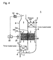
- FIG. 4 is a schematic configuration diagram that illustrates a device for recovering residual heat from exhaust gas according to a second embodiment.
- the device 1 for recovering residual heat according to the second embodiment has the same configuration as that of the device 1 for recovering residual heat described in the first embodiment except that white smoke to be discharged from the funnel to the atmosphere is suppressed. For that reason, the detailed description of the same configuration as that of the first embodiment will be omitted.
- the device 1 for recovering residual heat further includes a white-smoke detector 12, a heater 14, and a heating controller 22, besides the configuration described in Fig. 1 .
- the white-smoke detector 12 detects the white smoke to be discharged from the funnel 10 to the atmosphere.
- the white-smoke detector 12 is, for example, a remote surveillance camera provided near the funnel 10.
- the white-smoke detector 12 may be a sensor that measures the light transmittance of the exhaust gas.
- the heater 14 transfers the heat of the exhaust gas of the upstream duct 6 to the downstream side of the exhaust gas flow of the condensation economizer 4, and heats the exhaust gas of the downstream side of the exhaust gas flow of the condensation economizer 4.
- the heater 14 is a gas-gas heater having a heat recovery section 16 and a reheating section 18.
- the gas-gas heater 14 transfers the heat of the exhaust gas of the upstream duct 6 to the downstream side of the exhaust gas flow of the condensation economizer 4 by rotating a heat transfer layer plate 20 so that the heat recovery section 16 and the reheating section 18 described later are alternately situated, and heats the exhaust gas of the downstream side of the exhaust gas flow of the condensation economizer 4.
- the heat recovery section 16 gives the heat transfer layer plate 20 the residual heat of the exhaust gas on the downstream side of the exhaust gas flow of the dry economizer 2 to recovery the residual heat.
- the heat of the exhaust gas of the upstream duct 6 to be transferred to the downstream side of the exhaust gas flow of the condensation economizer 4 is obtained by being recovered by the heat recovery section 16.
- the temperature of the exhaust gas of the downstream side of the exhaust gas flow of the dry economizer 2. Accordingly, the temperature of the exhaust gas is lowered before flowing in the condensation economizer 4, whereby the exhaust gas is easily condensed by the condensation economizer 4.
- the temperature of the exhaust gas discharged from the dry economizer 2 is 180°C
- the exhaust gas subjected to the heat recovery by the heat recovery section 16 is lowered to 60 to 80°C.
- the reheating section 18 reheats the exhaust gas on the downstream side of the exhaust gas flow of the condensation economizer 4 by the residual heat recovered to the heat transfer layer plate 20 by the heat recovery section 16.
- the reheating section 18 reheats the exhaust gas on the downstream side of the exhaust gas flow of the condensation economizer 4 by the residual heat recovered to the heat transfer layer plate 20 by the heat recovery section 16.
- the heating controller 22 controls the heating state of the heater (the gas-gas heater) 14 based on the detection result of the white-smoke detector 12.
- the heating controller 22 may raise the rotational speed of the gas-gas heater 14 with the increase in concentration of the white smoke based on the detection result of the white-smoke detector 12.
- the heating controller 22 is a controller, and drives the motor 24, which rotates the heat transfer layer plate 20 of the gas-gas heater 14, based on the detection result of the white-smoke detector 12.
- FIG. 5 is a schematic configuration diagram that illustrates a device for recovering residual heat from exhaust gas according to the third embodiment.
- the device 1 for recovering residual heat from exhaust gas according to the third embodiment has the same configuration as the device 1 for recovering residual heat described in the second embodiment except that a bypass channel and a damper are provided instead of the gas-gas heater 14 as the heater, and thus, the detailed description of the same configuration will be omitted.
- the heater includes a bypass channel 28 and a damper 32.
- the bypass channel 28 connects the upstream duct 6 with the downstream duct 8, and joins a part of the exhaust gas of the upstream duct 6 on the downstream side of the exhaust gas flow of the condensation economizer 4.
- the damper 32 controls the flow rate of the exhaust gas of the bypass channel 28.
- the heating controller 36 increases the opening amount of the damper 32 with the increase in concentration of the white smoke based on the detection result of the white-smoke detector 12.
- the heating controller 36 is a controller, and drives the motor 38, which operates the damper 32, based on the detection result of the white-smoke detector 12.
- the installation locations or the numbers of the bypass channel and the damper are not particularly limited, but the installation locations may be changed and a plurality of them may be provided.
- a low temperature dry economizer separate from the dry economizer 2 may be provided, and the bypass channel and the damper may be provided on the downstream side of the low temperature dry economizer.
- a low temperature dry economizer 26, a bypass channel 30, and a damper 34 may be further included.
- the low temperature dry economizer 26 is arranged in the upstream duct 6 of the downstream side of the dry economizer 2 and performs the residual heat recovery of the exhaust gas in a temperature area of the temperature lower than that of the dry economizer 2. For example, when the temperature of the exhaust gas discharged from the dry economizer 2 is 180°C, the low temperature dry economizer 26 may be provided in the temperature area where the exhaust gas subjected to the residual heat recovery by the low temperature dry economizer 26 is lowered to 60 to 80°C.
- an outlet to-be-heated water of the low temperature dry economizer 26 after the heat exchange may be used as an inlet to-be-heated water of the dry economizer 2 via a deaerator.
- the bypass channel 30 connects the upstream duct 6 with the downstream duct 8, and joins a part of the exhaust gas of the downstream side of the low temperature dry economizer 26 on the downstream side of the exhaust gas flow of the condensation economizer 4.
- the damper 34 controls the flow rate of the exhaust gas of the bypass channel 30, that is, the flow rate of the exhaust subjected to the residual heat recovery by the low temperature dry economizer 26.
- the opening amount of the damper 34 is increased by driving the motor 40 of the heating controller (controller) 36 with the increase in concentration of the white smoke based on the detection result of the white-smoke detector 12.
- a part of the exhaust gas of the downstream side of the low temperature dry economizer 26 may be joined via the bypass channel 30 and the damper 34.
- a part of the exhaust gas of the downstream side of the dry economizer 2 having temperature higher than that of the exhaust gas of the downstream side of the low temperature dry economizer 26 may be joined via the bypass channel 28 and the damper 32.
Landscapes
- Engineering & Computer Science (AREA)
- Mechanical Engineering (AREA)
- General Engineering & Computer Science (AREA)
- Physics & Mathematics (AREA)
- Thermal Sciences (AREA)
- Chimneys And Flues (AREA)
- Instantaneous Water Boilers, Portable Hot-Water Supply Apparatuses, And Control Of Portable Hot-Water Supply Apparatuses (AREA)
- Engine Equipment That Uses Special Cycles (AREA)
Abstract
Description
- The present invention relates to a device for recovering residual heat from exhaust gas. Particularly, the present invention relates to a device for recovering residual heat from exhaust gas that includes a dry economizer which heats to-be-heated water by utilizing sensible heat of the exhaust gas, the dry economizer being provided in a duct extending to a funnel through which the exhaust gas is emitted to atmosphere; and a condensation economizer which heats to-be-heated water by utilizing latent heat of condensation of the exhaust gas, the condensation economizer being provided on the downstream side of the dry economizer.
- In related art, in a duct through which the exhaust gas from a boiler is circulated, an economizer is provided which heats a boiler water supply (to-be-heated water) using residual heat of the exhaust gas. The economizer recovers the residual heat of the exhaust gas by performing a heat exchange with the boiler water supply. Particularly, a condensation economizer has a configuration that is also able to recover latent heat discharged when vapor in the exhaust gas is condensed and becomes water. Thus, by using the condensation economizer together with a dry economizer that mainly recovers the sensible heat of the exhaust gas, the residual heat is able to be further recovered, which is capable of improving heating efficiency of the boiler.
- As the device for recovering residual heat from exhaust gas, for example,
Patent Document 1 discloses a boiler in which, in a duct through which the exhaust gas of a downward flow is circulated, a dry economizer, an air preheater, and a condensation economizer are sequentially disposed in series. InPatent Document 1, residual quantity of heat contained in the exhaust gas passed through the dry economizer is able to be recovered by a tubular air preheater, and the condensation economizer. Furthermore, in a water pipe group that is a major component of the condensation economizer, condensation is promoted, and a slightly wet portion partially exists. - Furthermore,
Patent Document 2 discloses a condensation economizer in which a sensible heat transfer area and a condensation heat transfer area are alternately provided in a duct through which the exhaust gas of downstream flow is circulated. Specifically, inPatent Document 2, a fin tube, through which a boiler water supply is circulated, is arranged in multiple stages, a front stage of the multi-stage fin tube is set to a sensible heat transfer area of a high temperature, a middle stage thereof is set to a condensation heat transfer area, and a rear stage thereof is set to a sensible heat transfer area of a low temperature, whereby the sensible heat and the latent heat of the exhaust gas are recovered in each heat transfer area. -
- Patent Document 1: Japanese Patent Application Laid-Open No.
11-118104 - Patent Document 2: Japanese Patent Application Laid-Open No.
2001-208302 - However, since the condensation economizer of the boiler of
Patent Document 1 is disposed in the duct through which the exhaust gas of downstream flow is circulated and a partial wet portion is generated in the water pipe group by the condensation of vapor in the exhaust gas, the water pipe group has a wet area and a dry area. The wet area and the dry area are changed in position along with a change in boiler load. That is, when the boiler load is changed, the temperature of the exhaust gas passing through the condensation economizer is changed. Thus, a position, where the exhaust gas amounts to a condensation temperature, is changed, a boundary position between the wet area and the dry area is changed. Accordingly, since the exhaust gas flows from the upside, the dry area is generated in the upper part of the condensation economizer, the wet area is generated in the lower part thereof, and a zone, where the drying and the wetting are repeated, is generated in the middle part thereof. In the middle part, the water pipe group repeats the cooling and the heating, and thus there is a possibility that stress corrosion cracking (SCC) may occur in the water pipe. - Furthermore, in
Patent Document 2, since the sensible heat transfer area and the condensation heat transfer area are alternately provided, the structure is complicated and the apparatus increases in size. In addition, since it is feared that the position of the condensation heat transfer area is changed due to a change in boiler load, similarly toPatent Document 1, a zone is generated where the drying and the wetting are repeated, whereby there is a possibility of the stress corrosion cracking being generated. - The present invention was made in view of the above circumstances, and an object thereof is to provide a device for recovering residual heat from exhaust gas that has a simple structure and is able to prevent the drying and wetting cycle in the condensation economizer.
- According to an embodiment of the present invention, the device for recovering residual heat from exhaust gas comprises a dry economizer which heats to-be-heated water by utilizing sensible heat of the exhaust gas, the dry economizer being provided in a duct extending to a funnel through which the exhaust gas is emitted to atmosphere; and a condensation economizer which heats to-be-heated water by utilizing latent heat of condensation of the exhaust gas, the condensation economizer being provided on the downstream side of the dry economizer, wherein the duct comprises an upstream duct in which the dry economizer is provided and a downstream duct connected to the upstream duct and directing the exhaust gas to flow upward, and wherein the condensation economizer is arranged in the downstream duct so that temperature of the exhaust gas amounts to condensation temperature at a vicinity of an upper part of the condensation economizer.
- In the device for recovering residual heat from exhaust gas, the condensation economizer is provided in a downstream duct that directs the exhaust gas to flow upward, and the device is configured so that temperature of the exhaust gas amounts to condensation temperature at a vicinity of the upper part of the condensation economizer. Thus, vapor in the exhaust gas is condensed in the vicinity of the upper part of the condensation economizer, and becomes a drain (condensed water). The generated drain falls down from vicinity of the upper part of the condensation economizer and comes into contact with the water pipe group constituting the condensation economizer, and thus, the outer wall of the water pipe is kept in a wet state from the upper part to the lower part. For this reason, the drying and wetting cycle is able to be prevented in the water pipe group in the condensation economizer, which is able to prevent the stress corrosion cracking.
Furthermore, when falling down from the vicinity of the upper part of the condensation economizer, since the generated drain comes into contact with the water pipe group and falls down so as to face the exhaust gas of the upward flow, it is possible to increase partial pressure of the vapor in the exhaust gas flowing in the condensation economizer. For this reason, the condensation amount of the condensation economizer is increased, the condensation efficiency rises, and the residual heat recovery rate of the exhaust gas rises. - In addition, the device for recovering residual heat from exhaust gas has a configuration in which the upstream duct is provided with the dry economizer and the condensation economizer is provided in the downstream duct which is connected to the upstream duct and directs the exhaust gas to flow upward. Thus, the device is able to be simply configured.
- Preferably, the device for recovering residual heat further comprises: a white-smoke detector which detects white smoke of the exhaust gas emitted to the atmosphere through the funnel; a heater which heats the exhaust gas on the downstream side of the condensation economizer in a flow direction of the exhaust gas by heat transfer from the exhaust gas in the upstream duct to the downstream side of the condensation economizer; and a heating controller which controls heating condition of the heater based on detection result of the white-smoke detector.
- Generally, since, in the exhaust gas, vapor in the exhaust gas is cooled and changed to water droplets, when the exhaust gas is discharged from the funnel to the atmosphere as it is, white smoke is easily generated. For that reason, in the device for recovering residual heat from exhaust gas, the exhaust gas heat of the upstream duct is transferred to the downstream side of the exhaust gas flow of the condensation economizer, and the exhaust gas of the downstream side of the exhaust gas flow of the condensation economizer is heated. As a result, it is possible to raise the temperature of the exhaust gas of the downstream side of the exhaust gas flow of the condensation economizer to lower the relative humidity of the gas after the mixture, which is able to suppress the occurrence of white smoke.
Furthermore, since it is possible to control the heating state of the heater based on the detection result of the white-smoke detector that detects white smoke of the exhaust gas emitted from the funnel to the atmosphere, the temperature of the exhaust gas is able to be adjusted so that the white smoke is not generated. - In the aforementioned case, the heater may be a gas heater which comprises: a heat recovery section at which residual heat of the exhaust gas is recovered by a heat exchanger plate on the downstream side of the dry economizer in the exhaust gas flow; and a reheating section at which the exhaust gas is reheated on the downstream side of the condensation economizer by the residual heat having been recovered by means of the heat exchanger plate at the heat recovery section, the gas heater rotating the heat exchanger plate so as to be placed in the heat recovery section and the reheating section alternately, and the heating controller may increase the rotational speed of the heat exchanger plate with the increase in concentration of the white smoke based on the detection result of the white-smoke detector.
- As a result, since the exhaust gas heat of the upstream duct is able to be transferred to the downstream side of the exhaust gas flow of the condensation economizer and the exhaust gas is able to be reheated on the downstream side of the exhaust gas flow of the condensation economizer, an occurrence of white smoke is able to be suppressed. Furthermore, since the exhaust gas heat of the upstream duct to be transferred to the downstream side of the exhaust gas flow of the condensation economizer is able to be obtained by being recovered in the heat recovery section, the temperature of the exhaust gas of the downstream side of the exhaust gas flow of the dry economizer is able to be lowered. Thus, the temperature of the exhaust gas is able to be lowered before flowing into the condensation economizer, whereby the exhaust gas is easily condensed by the condensation economizer.
Furthermore, since the rotational speed of the gas heater is raised with the increase in concentration of the white smoke based on the detection result of the white-smoke detector, the temperature of the exhaust gas is able to be effectively regulated so that white smoke is not generated. - Alternatively, the heater may comprise: a bypass channel through which the upstream duct is in communication with the downstream duct so that a portion of the exhaust gas in the upstream duct flows into the downstream side of the condensation economizer; and a damper which adjusts flow rate of the portion of the exhaust gas flowing in the bypass channel, and the heating controller may increase the opening amount of the damper with the increase in concentration of the white smoke based on the detection result of the white-smoke detector.
- As a result, since a portion of the exhaust gas in the upstream duct is capable of jointly flowing into the downstream side of the exhaust gas flow of the condensation economizer, it is possible to raise the temperature of the exhaust gas of the downstream side of the exhaust gas flow of the condensation economizer, thereby suppressing an occurrence of white smoke.
Furthermore, since the opening amount of the damper is able to be increased with the increase in concentration of the white smoke based on the detection result of the white-smoke detector, the flow rate of the exhaust gas of the bypass flow channel is able to be adjusted so that the white smoke is not generated. Thus, the temperature of the exhaust gas is able to be effectively adjusted.
In addition, the heater including the bypass channel and the damper has a simple structure and is able to reduce the equipment cost. - Moreover, the device for recovering residual heat may further comprise a spray nozzle which sprays water to the exhaust gas flowing in the condensation economizer, and the water sprayed to the exhaust gas by the spray nozzle may have a temperature between an the inlet temperature and the outlet temperature of the to-be-heated water in the condensation economizer.
Thus, since water is sprayed toward the exhaust gas flowing in the condensation economizer, it is possible to further improve the vapor partial pressure in the exhaust gas flowing in the condensation economizer. For this reason, the condensation amount in the condensation economizer is increased and the condensation efficiency is raised, whereby the residual heat recovery rate of the exhaust is raised.
Furthermore, since the temperature of water to be sprayed into the exhaust gas by the spray nozzle is set to a temperature between the inlet temperature and the outlet temperature of the to-be-heated water to the condensation economizer, a decline in condensation efficiency is able to be prevented without rapidly cooling the exhaust gas. - Further, it is preferable that the-to-be-heated water flows in the dry economizer and the condensation economizer in a direction that is opposite to a direction of the exhaust gas.
Thus, since the flow direction of the to-be-heated water flowing in the dry economizer and the condensation economizer is provided so as to face the flow direction of the exhaust gas, the heat recovery efficiency is able to be improved. - In the present invention, the condensation economizer is provided in a downstream duct that directs the exhaust gas to flow upward, and the device is configured so that temperature of the exhaust gas amounts to condensation temperature at a vicinity of the upper part of the condensation economizer. Thus, vapor in the exhaust gas is condensed in the vicinity of the upper part of the condensation economizer, and becomes a drain. The generated drain falls down from vicinity of the upper part of the condensation economizer and comes into contact with the water pipe group constituting the condensation economizer, and thus, the outer wall of the water pipe is kept in a wet state from the upper part to the lower part. For this reason, the drying and wetting cycle is able to be prevented in the water pipe group in the condensation economizer, which is able to prevent the stress corrosion cracking.
Furthermore, when falling down from the vicinity of the upper part of the condensation economizer, since the generated drain comes into contact with the water pipe group and falls down so as to face the exhaust gas of the upward flow, it is possible to increase partial pressure of the vapor in the exhaust gas flowing in the condensation economizer. For this reason, the condensation amount in the condensation economizer is increased, the condensation efficiency rises, and the residual heat recovery rate of the exhaust gas rises. - In addition, the device for recovering residual heat from exhaust gas has a configuration in which the upstream duct is provided with the dry economizer and the condensation economizer is provided in the downstream duct which is connected to the upstream duct and directs the exhaust gas to flow upward. Thus, the device is able to be simply configured.
-
-
Fig. 1 is a schematic configuration diagram that illustrates an example of the device for recovering residual heat from exhaust gas according to a first embodiment. -
Figs. 2A to 2C are schematic diagrams that illustrate installation examples of a spray nozzle. -
Figs. 3A and 3B are schematic configuration diagrams that illustrate modified examples of the device for recovering residual heat from exhaust gas according to the first embodiment. -
Fig. 4 is a schematic configuration diagram that illustrates an example of a device for recovering residual heat from exhaust gas according to a second embodiment. -
Fig. 5 is a schematic configuration diagram that illustrates an example of a device for recovering residual heat from exhaust gas according to a third embodiment. - Hereinafter, preferred embodiments of the present invention will be described in detail with reference to the drawings. However, sizes, materials, shapes, relative dispositions or the like of components described in the present embodiment do not purport to limit the scope of the present invention thereto but are mere description examples unless specifically described.
-
Fig. 1 is a schematic configuration diagram that illustrates an example of the device for recovering residual heat from exhaust gas according to a first embodiment of the present invention.Fig. 2 is a schematic diagram that illustrates an installation example of a spray nozzle provided at the vicinity of a condensation economizer. - The
device 1 for recovering residual heat from exhaust gas according to the present invention is provided in a duct connected to afunnel 10 that discharges the exhaust gas from a boiler to the atmosphere. As shown inFig. 1 , thedevice 1 for recovering residual heat from exhaust gas mainly includes adry economizer 2 and acondensation economizer 4.
Thedry economizer 2 and thecondensation economizer 4 include a water pipe through which the to-be-heated water (a boiler water) is circulated. A material of the water pipe preferably uses SUS316L added with molybdenum in austenitic stainless steel from the viewpoint of improving a corrosion resistance. - The
dry economizer 2 heats the to-be heated water using the sensible heat of the exhaust gas, and is provided on the upstream side (an upstream duct 6) of the duct. The exhaust gas subjected to the heat exchange with the to-be-heated water in thedry economizer 2 drops in temperature owing to residual heat recovery. For example, when the temperature of the exhaust gas flowing in thedry economizer 2 is 300°C, the temperature of the exhaust gas flowing out of thedry economizer 2 drops to 180°C. In this case, for example, the inlet temperature of the to-be-heated water to thedry economizer 2 may be 150°C, and the outlet temperature thereof may be 250°C. - The
condensation economizer 4 is arranged on the downstream side of thedry economizer 2 to heat the to-be-heated water using the latent heat of the condensation of the exhaust gas, and is provided on the downstream side (the downstream duct 8) of the duct. Thedownstream duct 8 is connected to theupstream duct 6 to direct the exhaust gas to flow upward. Thecondensation economizer 4 is provided so that the exhaust gas amounts to the condensation temperature at the vicinity of theupper part 5. In the present embodiment, the condensation temperature of the exhaust gas is 58 to 62°C. For example, another dry economizer, which lowers the temperature of the exhaust gas, may be provided on the upstream side of thecondensation economizer 4 so that the exhaust gas amounts to the condensation temperature at the vicinity of theupper part 5 of thecondensation economizer 4. - In addition, the flow direction of the to-be-heated water flowing in the
dry economizer 2 and thecondensation economizer 4 is provided so as to face the flow direction of the exhaust gas.
Thus, since the flow direction of the to-be-heated water flowing in thedry economizer 2 and thecondensation economizer 4 is provided so as to face the flow direction of the exhaust gas, the heat recovery efficiency can be improved. - In this manner, the
device 1 for recovering residual heat from exhaust gas mentioned above is configured such that thecondensation economizer 4 is provided in thedownstream duct 8 directing the exhaust gas to flow upward, and the exhaust gas amounts to the condensation temperature at the vicinity of theupper part 5 of thecondensation economizer 4. Thus, vapor in the exhaust gas is condensed at the vicinity of theupper part 5 of thecondensation economizer 4 and becomes the drain (the condensed water).
Since the generated drain falls down from the vicinity of theupper part 5 of the condensation economizer and comes into contact with the water pipe group constituting thecondensation economizer 4, the outer wall of the water pipe is kept in the wet state from the upper part to the lower part. For this reason, the drying and wetting cycle is able to be prevented in the water pipe group of thecondensation economizer 4, whereby the stress corrosion cracking is able to be prevented. - Furthermore, since the generated drain falls down so as to come into contact with the water pipe group and face the exhaust gas of the upward flow when falling down from the vicinity of the
upper part 5 of thecondensation economizer 4, it is possible to increase the partial pressure of vapor in the exhaust gas flowing in thecondensation economizer 4. For this reason, the condensation amount in the condensation economizer is increased, the condensation efficiency rises, and the residual heat recovery rate of the exhaust gas rises.
In addition, the drain comes into contact with the water pipe group of thecondensation economizer 4 or the exhaust gas of the upward flow, and then is discharged from thedrain outlet 7. - In addition, since the
device 1 for recovering residual heat from exhaust gas of the present embodiment is configured such that thecondensation economizer 4 is provided in theupstream duct 6 provided with thedry economizer 2 and in thedownstream duct 8 that is connected to theupstream duct 6 and directs the exhaust gas to flow upward, it is possible to easily assemble and manufacture the device for recovering residual heat. - Furthermore, as shown in
Fig. 2 , thedevice 1 for recovering residual heat from exhaust gas may include aspray nozzle 9 that sprays water toward the exhaust gas flowing in thecondensation economizer 4.
As shown inFig. 2A , thespray nozzle 9 may be provided on the lower part side (the exhaust gas flow upstream side) of thecondensation economizer 4, and, as shown inFig. 2B , thespray nozzle 9 may be provided in an inner part of thecondensation economizer 4. Furthermore, as shown inFig. 2C , thespray nozzle 9 may be provided on an upper part side (the exhaust gas flow downstream side) of thecondensation economizer 4. - Thus, since water is sprayed toward the exhaust gas flowing in the
condensation economizer 4, it is possible to further increase the partial pressure of vapor in the exhaust gas flowing in thecondensation economizer 4. For this reason, the condensation amount in thecondensation economizer 4 is increased, the condensation efficiency rises, and the residual heat recovery rate of the exhaust gas rises.
Particularly, as shown inFig. 2C , when thespray nozzle 9 is provided in the upper part side of thecondensation economizer 4, it is possible to expect that the drying of thewater pipe 11 constituting thecondensation economizer 4 is prevented, whereby the outer wall of thewater pipe 11 is generally kept in the wet state. Thus, it is possible to increase the partial pressure of vapor in the exhaust gas and prevent the drying and wetting cycle in thecondensation economizer 4, which is able to effectively prevent the stress corrosion cracking. - In addition, the temperature of water to be sprayed to the exhaust gas by the
spray nozzle 9 is set to a temperature between the inlet temperature and the outlet temperature of the to-be-heated water to thecondensation economizer 4.
For example, when the inlet temperature of the to-be-heated water to thecondensation economizer 4 is 20°C, and the outlet temperature thereof is 60°C, as shown inFig. 2A , the temperature of water to be sprayed from the lower part side of thecondensation economizer 4 may be 55°C. Furthermore, as shown inFig. 2C , the temperature of water to be sprayed from the upper part side of thecondensation economizer 4 may be 20°C.
Thus, since the temperature of water to be sprayed to the exhaust gas by the spray nozzle is set to the temperature between the inlet temperature and the outlet temperature of the to-be-heated water to the condensation economizer, it is possible to prevent a decline in condensation efficiency without rapidly cooling the exhaust gas. - In the embodiment mentioned above, although the
upstream duct 6 having the exhaust gas flow of the downward flow is described as an installation example of thedry economizer 2, the installation location of thedry economizer 2 is not particularly limited, if the location is within the duct having the exhaust gas flow of one direction flow. -
Fig. 3 is a schematic configuration diagram that shows a modified example of the device for recovering residual heat from exhaust gas according to the first embodiment, and is an example of an installation location of the dry economizer. - As an example of the installation location of the
dry economizer 2, for example, thedry economizer 2 may be installed in theupstream duct 6 having the exhaust gas flow of a horizontal direction shown inFig. 3A and may be installed in theupstream duct 6 having the exhaust gas flow of the upward flow shown inFig. 3B . - Next, the device for recovering residual heat from exhaust gas according to a second embodiment will be described.
Fig. 4 is a schematic configuration diagram that illustrates a device for recovering residual heat from exhaust gas according to a second embodiment. - The
device 1 for recovering residual heat according to the second embodiment has the same configuration as that of thedevice 1 for recovering residual heat described in the first embodiment except that white smoke to be discharged from the funnel to the atmosphere is suppressed. For that reason, the detailed description of the same configuration as that of the first embodiment will be omitted. - As shown in
Fig. 4 , thedevice 1 for recovering residual heat further includes a white-smoke detector 12, aheater 14, and aheating controller 22, besides the configuration described inFig. 1 . - The white-
smoke detector 12 detects the white smoke to be discharged from thefunnel 10 to the atmosphere. The white-smoke detector 12 is, for example, a remote surveillance camera provided near thefunnel 10. Furthermore, the white-smoke detector 12 may be a sensor that measures the light transmittance of the exhaust gas. - The
heater 14 transfers the heat of the exhaust gas of theupstream duct 6 to the downstream side of the exhaust gas flow of thecondensation economizer 4, and heats the exhaust gas of the downstream side of the exhaust gas flow of thecondensation economizer 4.
In the present embodiment, theheater 14 is a gas-gas heater having aheat recovery section 16 and a reheating section 18. The gas-gas heater 14 transfers the heat of the exhaust gas of theupstream duct 6 to the downstream side of the exhaust gas flow of thecondensation economizer 4 by rotating a heattransfer layer plate 20 so that theheat recovery section 16 and the reheating section 18 described later are alternately situated, and heats the exhaust gas of the downstream side of the exhaust gas flow of thecondensation economizer 4. - The
heat recovery section 16 gives the heattransfer layer plate 20 the residual heat of the exhaust gas on the downstream side of the exhaust gas flow of thedry economizer 2 to recovery the residual heat. In this manner, the heat of the exhaust gas of theupstream duct 6 to be transferred to the downstream side of the exhaust gas flow of thecondensation economizer 4 is obtained by being recovered by theheat recovery section 16. Thus, it is possible to lower the temperature of the exhaust gas of the downstream side of the exhaust gas flow of thedry economizer 2. Accordingly, the temperature of the exhaust gas is lowered before flowing in thecondensation economizer 4, whereby the exhaust gas is easily condensed by thecondensation economizer 4.
For example, when the temperature of the exhaust gas discharged from thedry economizer 2 is 180°C, the exhaust gas subjected to the heat recovery by theheat recovery section 16 is lowered to 60 to 80°C. - The reheating section 18 reheats the exhaust gas on the downstream side of the exhaust gas flow of the
condensation economizer 4 by the residual heat recovered to the heattransfer layer plate 20 by theheat recovery section 16. Thus, it is possible to transfer the heat of the exhaust gas of theupstream duct 6 to the downstream side of the exhaust gas flow of thecondensation economizer 4 and reheat the exhaust gas on the downstream side of the exhaust gas flow of thecondensation economizer 4. Accordingly, it is possible to raise the temperature of the exhaust gas, lower the relative humidity of the gas after the mixture, and suppress the occurrence of white smoke.
For example, when the temperature of the exhaust gas discharged from thecondensation economizer 4 is 30 to 50°C, the exhaust gas reheated by the reheating section 18 is raised to 80 to 100°C. - The
heating controller 22 controls the heating state of the heater (the gas-gas heater) 14 based on the detection result of the white-smoke detector 12. In the present embodiment, theheating controller 22 may raise the rotational speed of the gas-gas heater 14 with the increase in concentration of the white smoke based on the detection result of the white-smoke detector 12. In addition, theheating controller 22 is a controller, and drives themotor 24, which rotates the heattransfer layer plate 20 of the gas-gas heater 14, based on the detection result of the white-smoke detector 12.
In this manner, since the rotational speed of the gas-gas heater 14 is raised with the increase in concentration of the white smoke based on the detection result of the white-smoke detector 12, it is possible to effectively adjust the temperature of the exhaust gas so that the white smoke is not generated. - Next, a device for recovering residual heat according to a third embodiment will be described.
Fig. 5 is a schematic configuration diagram that illustrates a device for recovering residual heat from exhaust gas according to the third embodiment. - The
device 1 for recovering residual heat from exhaust gas according to the third embodiment has the same configuration as thedevice 1 for recovering residual heat described in the second embodiment except that a bypass channel and a damper are provided instead of the gas-gas heater 14 as the heater, and thus, the detailed description of the same configuration will be omitted. - As shown in
Fig. 5 , the heater includes abypass channel 28 and adamper 32. Thebypass channel 28 connects theupstream duct 6 with thedownstream duct 8, and joins a part of the exhaust gas of theupstream duct 6 on the downstream side of the exhaust gas flow of thecondensation economizer 4. Thedamper 32 controls the flow rate of the exhaust gas of thebypass channel 28. - In this case, the
heating controller 36 increases the opening amount of thedamper 32 with the increase in concentration of the white smoke based on the detection result of the white-smoke detector 12. In addition, theheating controller 36 is a controller, and drives themotor 38, which operates thedamper 32, based on the detection result of the white-smoke detector 12. - As a result, since it is possible to join a part of the exhaust gas of the
upstream duct 6 on the downstream side of the exhaust gas flow of thecondensation economizer 4, it is possible to raise the temperature of the exhaust gas of the downstream side of the exhaust gas flow of thecondensation economizer 4 to suppress the occurrence of white smoke.
Furthermore, since it is possible to increase the opening amount of thedamper 32 with the increase in concentration of the white smoke based on the detection result of the white-smoke detector 12, it is possible to control the flow rate of the exhaust gas of thebypass channel 28 so that the white smoke is not generated. Thus, it is possible to effectively adjust the temperature of the exhaust gas.
In addition, since the heater including thebypass channel 28 and thedamper 32 has a simple structure, the equipment cost is able to be reduced. - In addition, the installation locations or the numbers of the bypass channel and the damper are not particularly limited, but the installation locations may be changed and a plurality of them may be provided. For example, in order that the exhaust gas amounts to the condensation temperature at the vicinity of the
upper part 5 of thecondensation economizer 4, a low temperature dry economizer separate from thedry economizer 2 may be provided, and the bypass channel and the damper may be provided on the downstream side of the low temperature dry economizer.
Specifically, as shown inFig. 5 , besides the configuration mentioned above, a low temperaturedry economizer 26, abypass channel 30, and adamper 34 may be further included. - The low temperature
dry economizer 26 is arranged in theupstream duct 6 of the downstream side of thedry economizer 2 and performs the residual heat recovery of the exhaust gas in a temperature area of the temperature lower than that of thedry economizer 2. For example, when the temperature of the exhaust gas discharged from thedry economizer 2 is 180°C, the low temperaturedry economizer 26 may be provided in the temperature area where the exhaust gas subjected to the residual heat recovery by the low temperaturedry economizer 26 is lowered to 60 to 80°C.
By recovering the remaining residual heat of the exhaust gas discharged from thedry economizer 2 through such a low temperaturedry economizer 26, it is possible to lower the temperature of the exhaust gas flowing in thecondensation economizer 4 and enhance the condensation efficiency of thecondensation economizer 4.
In addition, although it is not illustrated, from the viewpoint of improving the heating efficiency, an outlet to-be-heated water of the low temperaturedry economizer 26 after the heat exchange may be used as an inlet to-be-heated water of thedry economizer 2 via a deaerator. - The
bypass channel 30 connects theupstream duct 6 with thedownstream duct 8, and joins a part of the exhaust gas of the downstream side of the low temperaturedry economizer 26 on the downstream side of the exhaust gas flow of thecondensation economizer 4. Thedamper 34 controls the flow rate of the exhaust gas of thebypass channel 30, that is, the flow rate of the exhaust subjected to the residual heat recovery by the low temperaturedry economizer 26. Similarly to thedamper 32 mentioned above, the opening amount of thedamper 34 is increased by driving themotor 40 of the heating controller (controller) 36 with the increase in concentration of the white smoke based on the detection result of the white-smoke detector 12. - As a result, it is possible to select the temperature of the exhaust gas of the
upstream duct 6 that is joined on the downstream side of the exhaust gas flow of thecondensation economizer 4. For example, from the viewpoint of reliably performing the temperature control of the exhaust gas of the downstream side of the exhaust gas flow of thecondensation economizer 4 so that the white smoke is not generated, a part of the exhaust gas of the downstream side of the low temperaturedry economizer 26 may be joined via thebypass channel 30 and thedamper 34. Furthermore, from the viewpoint of suppressing a decline in heating efficiency, as shown inFig. 5 , a part of the exhaust gas of the downstream side of thedry economizer 2 having temperature higher than that of the exhaust gas of the downstream side of the low temperaturedry economizer 26 may be joined via thebypass channel 28 and thedamper 32. - As mentioned above, an example of the present invention was described in detail, the present invention is not limited thereto, but various improvements or modifications may be performed within the scope of not departing the gist of the present invention.
For example, it is needless to say that the first to third embodiments mentioned above may be suitably combined with each other. -
1 device for recovering residual heat 2 dry economizer 4 condensation economizer 6 upstream damper 7 drain outlet 8 downstream duct 9 spray nozzle 10 funnel 11 water pipe 12 white- smoke detector 14 gas- gas heater 16 heat recovery section 18 reheating section 20 heat transfer layer plate 22 controller (heating controller) 26 low temperature dry economizer 28 bypass channel 30 bypass channel 32 damper 34 damper 36 controller (heating controller)
Claims (6)
- A device for recovering residual heat from exhaust gas, the device comprising:a dry economizer which heats to-be-heated water by utilizing sensible heat of the exhaust gas, the dry economizer being provided in a duct extending to a funnel through which the exhaust gas is emitted to atmosphere; anda condensation economizer which heats to-be-heated water by utilizing latent heat of condensation of the exhaust gas, the condensation economizer being provided on a downstream side of the dry economizer,wherein the duct comprises an upstream duct in which the dry economizer is provided and a downstream duct connected to the upstream duct and directing the exhaust gas to flow upwardly, andwherein the condensation economizer is arranged in the downstream duct so that temperature of the exhaust gas amounts to condensation temperature at a vicinity of an upper part of the condensation economizer.
- The device for recovering residual heat according to claim 1, further comprising:a white-smoke detector which detects white smoke of the exhaust gas emitted to the atmosphere through the funnel;a heater which heats the exhaust gas on a downstream side of the condensation economizer in a flow direction of the exhaust gas by heat transfer from the exhaust gas in the upstream duct to the downstream side of the condensation economizer; anda heating controller which controls heating condition of the heater based on detection result of the white-smoke detector.
- The device for recovering residual heat according to claim 2,
wherein the heater is a gas heater which comprises: a heat recovery section at which residual heat of the exhaust gas is recovered by a heat exchanger plate on a downstream side of the dry economizer in the flow of the exhaust gas; and a reheating section at which the exhaust gas is reheated on the downstream side of the condensation economizer by the residual heat having been recovered by means of the heat exchanger plate at the heat recovery section, the gas heater rotating the heat exchanger plate so as to be placed in the heat recovery section and the reheating section alternately, and
wherein the heating controller increases a rotational speed of the heat exchanger plate with increase in concentration of the white smoke based on the detection result of the white-smoke detector. - The device for recovering residual heat according to claim 2,
wherein the heater comprises: a bypass channel through which the upstream duct is in communication with the downstream duct so that a portion of the exhaust gas in the upstream duct flows into the downstream side of the condensation economizer; and a damper which adjusts flow rate of the portion of the exhaust gas flowing in the bypass channel, and
wherein the heating controller increases an opening amount of the damper with increase in concentration of the white smoke based on the detection result of the white-smoke detector. - The device for recovering residual heat according to any one of claims 1 to 4, further comprising:a spray nozzle which sprays water to the exhaust gas flowing in the condensation economizer,wherein the water sprayed to the exhaust gas by the spray nozzle has temperature between an inlet temperature and an outlet temperature of the to-be-heated water in the condensation economizer.
- The device for recovering residual heat according to claim 1, wherein the to-be-heated water flows in the dry economizer and the condensation economizer in a direction that is opposite to a direction of the exhaust gas.
Applications Claiming Priority (2)
| Application Number | Priority Date | Filing Date | Title |
|---|---|---|---|
| JP2010144718A JP5351840B2 (en) | 2010-06-25 | 2010-06-25 | Waste heat recovery system for exhaust gas |
| PCT/JP2011/063463 WO2011162117A1 (en) | 2010-06-25 | 2011-06-13 | Exhaust gas residual heat recovery device |
Publications (3)
| Publication Number | Publication Date |
|---|---|
| EP2587143A1 true EP2587143A1 (en) | 2013-05-01 |
| EP2587143A4 EP2587143A4 (en) | 2017-11-22 |
| EP2587143B1 EP2587143B1 (en) | 2020-02-12 |
Family
ID=45371311
Family Applications (1)
| Application Number | Title | Priority Date | Filing Date |
|---|---|---|---|
| EP11798003.7A Active EP2587143B1 (en) | 2010-06-25 | 2011-06-13 | Exhaust gas residual heat recovery device |
Country Status (8)
| Country | Link |
|---|---|
| US (1) | US20130125841A1 (en) |
| EP (1) | EP2587143B1 (en) |
| JP (1) | JP5351840B2 (en) |
| KR (1) | KR101364944B1 (en) |
| CN (1) | CN102918324B (en) |
| ES (1) | ES2774948T3 (en) |
| SA (1) | SA111320546B1 (en) |
| WO (1) | WO2011162117A1 (en) |
Cited By (2)
| Publication number | Priority date | Publication date | Assignee | Title |
|---|---|---|---|---|
| AT519237A4 (en) * | 2016-12-21 | 2018-05-15 | Herz Energietechnik Gmbh | Plant for the recovery of heat |
| EP3279560A4 (en) * | 2015-03-31 | 2018-12-26 | Mitsubishi Hitachi Power Systems, Ltd. | Boiler, steam-generating plant provided with same, and method for operating boiler |
Families Citing this family (13)
| Publication number | Priority date | Publication date | Assignee | Title |
|---|---|---|---|---|
| EP2609983A1 (en) * | 2011-12-29 | 2013-07-03 | Brunnschweiler S.A. | Method and system for processing hot humid air resulting from an industrial process,prior to expelling it into the outside air, to recover water and remove the plume |
| JP2013204972A (en) * | 2012-03-29 | 2013-10-07 | Hitachi Zosen Corp | Waste treatment facility |
| CN103149043A (en) * | 2013-01-30 | 2013-06-12 | 浙江中烟工业有限责任公司 | Real-time monitoring system and monitoring method of heat efficiency of condensing gas boiler |
| KR20140143926A (en) * | 2013-06-10 | 2014-12-18 | 현대중공업 주식회사 | Economizer having by-pass part |
| JP5931827B2 (en) | 2013-09-25 | 2016-06-08 | 三菱重工業株式会社 | Quattro Generation System |
| JP6552904B2 (en) * | 2015-07-29 | 2019-07-31 | 三菱日立パワーシステムズ株式会社 | Exhaust gas latent heat recovery system |
| US10221726B2 (en) * | 2015-12-21 | 2019-03-05 | Cockerill Maintenance & Ingenierie S.A. | Condensing heat recovery steam generator |
| KR101693166B1 (en) * | 2016-07-12 | 2017-01-06 | 정수영 | Nutsche filtering and drying apparatus for liquid powder mixture |
| KR101816212B1 (en) * | 2016-09-12 | 2018-01-08 | 두산중공업 주식회사 | Apparatus for analyzing influence of combustibles |
| US11054146B2 (en) * | 2019-01-23 | 2021-07-06 | Grand Mate Co., Ltd. | Oven |
| CN112066777A (en) * | 2020-08-27 | 2020-12-11 | 合肥宽信机电有限公司 | Fin type coal economizer directly contacting with flame |
| CN113757768A (en) * | 2021-09-16 | 2021-12-07 | 中国北方发动机研究所(天津) | Box type high-temperature tail gas waste heat heating device |
| CN114717402B (en) * | 2022-04-06 | 2024-06-11 | 江苏中基新能源科技集团有限公司 | Annealing furnace waste heat utilization and air purification system |
Family Cites Families (13)
| Publication number | Priority date | Publication date | Assignee | Title |
|---|---|---|---|---|
| US4031862A (en) * | 1976-03-10 | 1977-06-28 | Smith Frank J | Economizer |
| SE409237B (en) * | 1977-11-30 | 1979-08-06 | Stal Laval Apparat Ab | ANGPANNA OR HEAT EXCHANGER FOR ENERGY RECOVERY OF GASES CONTAINING SUBSTANCE |
| US4660511A (en) * | 1986-04-01 | 1987-04-28 | Anderson J Hilbert | Flue gas heat recovery system |
| SE468296B (en) * | 1991-12-17 | 1992-12-07 | Svenska Rotor Maskiner Ab | PROCEDURES PROVIDE OPTIMUM ENERGY EXCHANGE IN REGENERATIVE HEAT EXCHANGE, WHEN HEAT TRANSMISSION ELEMENTS ARE STARTED WITH WATER |
| US5368096A (en) * | 1993-12-02 | 1994-11-29 | The Babcock & Wilcox Company | Condensing heat exchanger scrubbing system |
| US5567215A (en) * | 1994-09-12 | 1996-10-22 | The Babcock & Wilcox Company | Enhanced heat exchanger flue gas treatment using steam injection |
| JPH11118104A (en) * | 1997-10-20 | 1999-04-30 | Mitsubishi Heavy Ind Ltd | Boiler |
| CN2338614Y (en) * | 1998-09-22 | 1999-09-15 | 王智民 | Natural gas boiler with recovery of heat and moisture from flue gas |
| CN1097151C (en) * | 1998-10-23 | 2002-12-25 | 株式会社日立制作所 | Gas turbine power generation equipment and air humidifying apparatus |
| JP4570187B2 (en) * | 1999-11-22 | 2010-10-27 | 三浦工業株式会社 | Exhaust gas heat exchanger |
| JP2001208302A (en) * | 2000-01-28 | 2001-08-03 | Kawasaki Thermal Engineering Co Ltd | Condensation type economizer for oxygen burning boiler |
| JP2009264663A (en) * | 2008-04-25 | 2009-11-12 | Miura Co Ltd | Economizer and boiler |
| CN101334159B (en) * | 2008-08-06 | 2010-09-29 | 卓永冰 | Condensation water automatic discharging energy conservation equipment |
-
2010
- 2010-06-25 JP JP2010144718A patent/JP5351840B2/en active Active
-
2011
- 2011-06-13 CN CN201180026535.0A patent/CN102918324B/en not_active Expired - Fee Related
- 2011-06-13 WO PCT/JP2011/063463 patent/WO2011162117A1/en active Application Filing
- 2011-06-13 ES ES11798003T patent/ES2774948T3/en active Active
- 2011-06-13 KR KR1020127033249A patent/KR101364944B1/en active IP Right Grant
- 2011-06-13 EP EP11798003.7A patent/EP2587143B1/en active Active
- 2011-06-13 US US13/805,808 patent/US20130125841A1/en not_active Abandoned
- 2011-06-22 SA SA111320546A patent/SA111320546B1/en unknown
Non-Patent Citations (1)
| Title |
|---|
| See references of WO2011162117A1 * |
Cited By (4)
| Publication number | Priority date | Publication date | Assignee | Title |
|---|---|---|---|---|
| EP3279560A4 (en) * | 2015-03-31 | 2018-12-26 | Mitsubishi Hitachi Power Systems, Ltd. | Boiler, steam-generating plant provided with same, and method for operating boiler |
| US10844753B2 (en) | 2015-03-31 | 2020-11-24 | Mitsubishi Hitachi Power Systems, Ltd. | Boiler, steam-generating plant provided with same, and method for operating boiler |
| AT519237A4 (en) * | 2016-12-21 | 2018-05-15 | Herz Energietechnik Gmbh | Plant for the recovery of heat |
| AT519237B1 (en) * | 2016-12-21 | 2018-05-15 | Herz Energietechnik Gmbh | Plant for the recovery of heat |
Also Published As
| Publication number | Publication date |
|---|---|
| ES2774948T3 (en) | 2020-07-23 |
| EP2587143A4 (en) | 2017-11-22 |
| JP5351840B2 (en) | 2013-11-27 |
| JP2012007818A (en) | 2012-01-12 |
| EP2587143B1 (en) | 2020-02-12 |
| KR101364944B1 (en) | 2014-02-19 |
| KR20130020809A (en) | 2013-02-28 |
| US20130125841A1 (en) | 2013-05-23 |
| SA111320546B1 (en) | 2014-08-25 |
| WO2011162117A1 (en) | 2011-12-29 |
| CN102918324A (en) | 2013-02-06 |
| CN102918324B (en) | 2015-07-08 |
Similar Documents
| Publication | Publication Date | Title |
|---|---|---|
| EP2587143A1 (en) | Exhaust gas residual heat recovery device | |
| JP5260585B2 (en) | Coal-fired power plant and method for operating coal-fired power plant | |
| JP2014504548A5 (en) | ||
| CN104595919B (en) | A kind of energy-saving combustion gas pollutant disposal system of utilization thermal power plant used heat | |
| KR101892887B1 (en) | Heat exchanger and method for controlling heat exchanger | |
| RU2436011C1 (en) | Flue gas heat utilisation device and method of its operation | |
| US20160238245A1 (en) | Flue gas heat recovery system | |
| JP5182570B2 (en) | Water heater | |
| CA3061868A1 (en) | Flue gas energy recovery system and method | |
| CN109078463A (en) | Wet desulphurization eliminating white smoke chimney | |
| CN206478668U (en) | Eliminate the device of the white plume of chimney | |
| CN105423289B (en) | A kind of condensation prevention system and method for flue gas outer circulation combustion apparatus | |
| CN107062613A (en) | A kind of method that wall-hung boiler is changed condensing by on-condensing | |
| CN108026606A (en) | Continuous annealing apparatus | |
| JP2019090559A (en) | Temperature controller of heat exchanger for boiler exhaust gas | |
| CN205505002U (en) | Efficient air cooling fire dust interceptor | |
| JP4324245B2 (en) | Combustion device | |
| US20100212607A1 (en) | Energy recovery device | |
| CN106989374A (en) | A kind of industrial heat homogeneous solution-type reactor | |
| JP2008039389A (en) | Combustion device | |
| JP3037483U (en) | Air heater for white smoke prevention | |
| WO2015140158A1 (en) | Condensing hot air generator | |
| JPH0722282U (en) | Temperature control device for heat exchanger | |
| CN107366896A (en) | A kind of heat energy recycling steam generator system |
Legal Events
| Date | Code | Title | Description |
|---|---|---|---|
| PUAI | Public reference made under article 153(3) epc to a published international application that has entered the european phase |
Free format text: ORIGINAL CODE: 0009012 |
|
| 17P | Request for examination filed |
Effective date: 20121102 |
|
| AK | Designated contracting states |
Kind code of ref document: A1 Designated state(s): AL AT BE BG CH CY CZ DE DK EE ES FI FR GB GR HR HU IE IS IT LI LT LU LV MC MK MT NL NO PL PT RO RS SE SI SK SM TR |
|
| DAX | Request for extension of the european patent (deleted) | ||
| RA4 | Supplementary search report drawn up and despatched (corrected) |
Effective date: 20171019 |
|
| RIC1 | Information provided on ipc code assigned before grant |
Ipc: F28D 19/04 20060101ALI20171013BHEP Ipc: F22D 1/12 20060101ALI20171013BHEP Ipc: F22D 1/00 20060101ALI20171013BHEP Ipc: F22D 1/02 20060101AFI20171013BHEP Ipc: F23J 15/06 20060101ALI20171013BHEP |
|
| GRAP | Despatch of communication of intention to grant a patent |
Free format text: ORIGINAL CODE: EPIDOSNIGR1 |
|
| STAA | Information on the status of an ep patent application or granted ep patent |
Free format text: STATUS: GRANT OF PATENT IS INTENDED |
|
| INTG | Intention to grant announced |
Effective date: 20180725 |
|
| GRAJ | Information related to disapproval of communication of intention to grant by the applicant or resumption of examination proceedings by the epo deleted |
Free format text: ORIGINAL CODE: EPIDOSDIGR1 |
|
| STAA | Information on the status of an ep patent application or granted ep patent |
Free format text: STATUS: REQUEST FOR EXAMINATION WAS MADE |
|
| STAA | Information on the status of an ep patent application or granted ep patent |
Free format text: STATUS: EXAMINATION IS IN PROGRESS |
|
| INTC | Intention to grant announced (deleted) | ||
| 17Q | First examination report despatched |
Effective date: 20181217 |
|
| GRAS | Grant fee paid |
Free format text: ORIGINAL CODE: EPIDOSNIGR3 |
|
| STAA | Information on the status of an ep patent application or granted ep patent |
Free format text: STATUS: GRANT OF PATENT IS INTENDED |
|
| GRAP | Despatch of communication of intention to grant a patent |
Free format text: ORIGINAL CODE: EPIDOSNIGR1 |
|
| INTG | Intention to grant announced |
Effective date: 20190816 |
|
| RIN1 | Information on inventor provided before grant (corrected) |
Inventor name: TERAMOTO, KENSHU Inventor name: SUGITA, RYOSUKE Inventor name: ICHIHARA, TAROU |
|
| GRAA | (expected) grant |
Free format text: ORIGINAL CODE: 0009210 |
|
| STAA | Information on the status of an ep patent application or granted ep patent |
Free format text: STATUS: THE PATENT HAS BEEN GRANTED |
|
| AK | Designated contracting states |
Kind code of ref document: B1 Designated state(s): AL AT BE BG CH CY CZ DE DK EE ES FI FR GB GR HR HU IE IS IT LI LT LU LV MC MK MT NL NO PL PT RO RS SE SI SK SM TR |
|
| REG | Reference to a national code |
Ref country code: GB Ref legal event code: FG4D |
|
| REG | Reference to a national code |
Ref country code: CH Ref legal event code: EP |
|
| REG | Reference to a national code |
Ref country code: AT Ref legal event code: REF Ref document number: 1232586 Country of ref document: AT Kind code of ref document: T Effective date: 20200215 |
|
| REG | Reference to a national code |
Ref country code: IE Ref legal event code: FG4D |
|
| REG | Reference to a national code |
Ref country code: DE Ref legal event code: R096 Ref document number: 602011064977 Country of ref document: DE |
|
| REG | Reference to a national code |
Ref country code: SE Ref legal event code: TRGR |
|
| REG | Reference to a national code |
Ref country code: ES Ref legal event code: FG2A Ref document number: 2774948 Country of ref document: ES Kind code of ref document: T3 Effective date: 20200723 |
|
| PG25 | Lapsed in a contracting state [announced via postgrant information from national office to epo] |
Ref country code: FI Free format text: LAPSE BECAUSE OF FAILURE TO SUBMIT A TRANSLATION OF THE DESCRIPTION OR TO PAY THE FEE WITHIN THE PRESCRIBED TIME-LIMIT Effective date: 20200212 Ref country code: NO Free format text: LAPSE BECAUSE OF FAILURE TO SUBMIT A TRANSLATION OF THE DESCRIPTION OR TO PAY THE FEE WITHIN THE PRESCRIBED TIME-LIMIT Effective date: 20200512 Ref country code: RS Free format text: LAPSE BECAUSE OF FAILURE TO SUBMIT A TRANSLATION OF THE DESCRIPTION OR TO PAY THE FEE WITHIN THE PRESCRIBED TIME-LIMIT Effective date: 20200212 |
|
| REG | Reference to a national code |
Ref country code: LT Ref legal event code: MG4D |
|
| REG | Reference to a national code |
Ref country code: NL Ref legal event code: MP Effective date: 20200212 |
|
| PG25 | Lapsed in a contracting state [announced via postgrant information from national office to epo] |
Ref country code: BG Free format text: LAPSE BECAUSE OF FAILURE TO SUBMIT A TRANSLATION OF THE DESCRIPTION OR TO PAY THE FEE WITHIN THE PRESCRIBED TIME-LIMIT Effective date: 20200512 Ref country code: GR Free format text: LAPSE BECAUSE OF FAILURE TO SUBMIT A TRANSLATION OF THE DESCRIPTION OR TO PAY THE FEE WITHIN THE PRESCRIBED TIME-LIMIT Effective date: 20200513 Ref country code: HR Free format text: LAPSE BECAUSE OF FAILURE TO SUBMIT A TRANSLATION OF THE DESCRIPTION OR TO PAY THE FEE WITHIN THE PRESCRIBED TIME-LIMIT Effective date: 20200212 Ref country code: LV Free format text: LAPSE BECAUSE OF FAILURE TO SUBMIT A TRANSLATION OF THE DESCRIPTION OR TO PAY THE FEE WITHIN THE PRESCRIBED TIME-LIMIT Effective date: 20200212 Ref country code: IS Free format text: LAPSE BECAUSE OF FAILURE TO SUBMIT A TRANSLATION OF THE DESCRIPTION OR TO PAY THE FEE WITHIN THE PRESCRIBED TIME-LIMIT Effective date: 20200612 |
|
| PG25 | Lapsed in a contracting state [announced via postgrant information from national office to epo] |
Ref country code: NL Free format text: LAPSE BECAUSE OF FAILURE TO SUBMIT A TRANSLATION OF THE DESCRIPTION OR TO PAY THE FEE WITHIN THE PRESCRIBED TIME-LIMIT Effective date: 20200212 |
|
| PG25 | Lapsed in a contracting state [announced via postgrant information from national office to epo] |
Ref country code: LT Free format text: LAPSE BECAUSE OF FAILURE TO SUBMIT A TRANSLATION OF THE DESCRIPTION OR TO PAY THE FEE WITHIN THE PRESCRIBED TIME-LIMIT Effective date: 20200212 Ref country code: PT Free format text: LAPSE BECAUSE OF FAILURE TO SUBMIT A TRANSLATION OF THE DESCRIPTION OR TO PAY THE FEE WITHIN THE PRESCRIBED TIME-LIMIT Effective date: 20200705 Ref country code: SK Free format text: LAPSE BECAUSE OF FAILURE TO SUBMIT A TRANSLATION OF THE DESCRIPTION OR TO PAY THE FEE WITHIN THE PRESCRIBED TIME-LIMIT Effective date: 20200212 Ref country code: RO Free format text: LAPSE BECAUSE OF FAILURE TO SUBMIT A TRANSLATION OF THE DESCRIPTION OR TO PAY THE FEE WITHIN THE PRESCRIBED TIME-LIMIT Effective date: 20200212 Ref country code: CZ Free format text: LAPSE BECAUSE OF FAILURE TO SUBMIT A TRANSLATION OF THE DESCRIPTION OR TO PAY THE FEE WITHIN THE PRESCRIBED TIME-LIMIT Effective date: 20200212 Ref country code: DK Free format text: LAPSE BECAUSE OF FAILURE TO SUBMIT A TRANSLATION OF THE DESCRIPTION OR TO PAY THE FEE WITHIN THE PRESCRIBED TIME-LIMIT Effective date: 20200212 Ref country code: SM Free format text: LAPSE BECAUSE OF FAILURE TO SUBMIT A TRANSLATION OF THE DESCRIPTION OR TO PAY THE FEE WITHIN THE PRESCRIBED TIME-LIMIT Effective date: 20200212 Ref country code: EE Free format text: LAPSE BECAUSE OF FAILURE TO SUBMIT A TRANSLATION OF THE DESCRIPTION OR TO PAY THE FEE WITHIN THE PRESCRIBED TIME-LIMIT Effective date: 20200212 |
|
| REG | Reference to a national code |
Ref country code: DE Ref legal event code: R097 Ref document number: 602011064977 Country of ref document: DE |
|
| REG | Reference to a national code |
Ref country code: AT Ref legal event code: MK05 Ref document number: 1232586 Country of ref document: AT Kind code of ref document: T Effective date: 20200212 |
|
| PLBE | No opposition filed within time limit |
Free format text: ORIGINAL CODE: 0009261 |
|
| STAA | Information on the status of an ep patent application or granted ep patent |
Free format text: STATUS: NO OPPOSITION FILED WITHIN TIME LIMIT |
|
| 26N | No opposition filed |
Effective date: 20201113 |
|
| PG25 | Lapsed in a contracting state [announced via postgrant information from national office to epo] |
Ref country code: MC Free format text: LAPSE BECAUSE OF FAILURE TO SUBMIT A TRANSLATION OF THE DESCRIPTION OR TO PAY THE FEE WITHIN THE PRESCRIBED TIME-LIMIT Effective date: 20200212 Ref country code: IT Free format text: LAPSE BECAUSE OF FAILURE TO SUBMIT A TRANSLATION OF THE DESCRIPTION OR TO PAY THE FEE WITHIN THE PRESCRIBED TIME-LIMIT Effective date: 20200212 Ref country code: AT Free format text: LAPSE BECAUSE OF FAILURE TO SUBMIT A TRANSLATION OF THE DESCRIPTION OR TO PAY THE FEE WITHIN THE PRESCRIBED TIME-LIMIT Effective date: 20200212 |
|
| REG | Reference to a national code |
Ref country code: CH Ref legal event code: PL |
|
| PG25 | Lapsed in a contracting state [announced via postgrant information from national office to epo] |
Ref country code: PL Free format text: LAPSE BECAUSE OF FAILURE TO SUBMIT A TRANSLATION OF THE DESCRIPTION OR TO PAY THE FEE WITHIN THE PRESCRIBED TIME-LIMIT Effective date: 20200212 Ref country code: SI Free format text: LAPSE BECAUSE OF FAILURE TO SUBMIT A TRANSLATION OF THE DESCRIPTION OR TO PAY THE FEE WITHIN THE PRESCRIBED TIME-LIMIT Effective date: 20200212 |
|
| GBPC | Gb: european patent ceased through non-payment of renewal fee |
Effective date: 20200613 |
|
| PG25 | Lapsed in a contracting state [announced via postgrant information from national office to epo] |
Ref country code: LU Free format text: LAPSE BECAUSE OF NON-PAYMENT OF DUE FEES Effective date: 20200613 |
|
| REG | Reference to a national code |
Ref country code: BE Ref legal event code: MM Effective date: 20200630 |
|
| PG25 | Lapsed in a contracting state [announced via postgrant information from national office to epo] |
Ref country code: GB Free format text: LAPSE BECAUSE OF NON-PAYMENT OF DUE FEES Effective date: 20200613 Ref country code: FR Free format text: LAPSE BECAUSE OF NON-PAYMENT OF DUE FEES Effective date: 20200630 Ref country code: IE Free format text: LAPSE BECAUSE OF NON-PAYMENT OF DUE FEES Effective date: 20200613 Ref country code: LI Free format text: LAPSE BECAUSE OF NON-PAYMENT OF DUE FEES Effective date: 20200630 Ref country code: CH Free format text: LAPSE BECAUSE OF NON-PAYMENT OF DUE FEES Effective date: 20200630 |
|
| PG25 | Lapsed in a contracting state [announced via postgrant information from national office to epo] |
Ref country code: BE Free format text: LAPSE BECAUSE OF NON-PAYMENT OF DUE FEES Effective date: 20200630 |
|
| PG25 | Lapsed in a contracting state [announced via postgrant information from national office to epo] |
Ref country code: TR Free format text: LAPSE BECAUSE OF FAILURE TO SUBMIT A TRANSLATION OF THE DESCRIPTION OR TO PAY THE FEE WITHIN THE PRESCRIBED TIME-LIMIT Effective date: 20200212 Ref country code: MT Free format text: LAPSE BECAUSE OF FAILURE TO SUBMIT A TRANSLATION OF THE DESCRIPTION OR TO PAY THE FEE WITHIN THE PRESCRIBED TIME-LIMIT Effective date: 20200212 Ref country code: CY Free format text: LAPSE BECAUSE OF FAILURE TO SUBMIT A TRANSLATION OF THE DESCRIPTION OR TO PAY THE FEE WITHIN THE PRESCRIBED TIME-LIMIT Effective date: 20200212 |
|
| PG25 | Lapsed in a contracting state [announced via postgrant information from national office to epo] |
Ref country code: MK Free format text: LAPSE BECAUSE OF FAILURE TO SUBMIT A TRANSLATION OF THE DESCRIPTION OR TO PAY THE FEE WITHIN THE PRESCRIBED TIME-LIMIT Effective date: 20200212 Ref country code: AL Free format text: LAPSE BECAUSE OF FAILURE TO SUBMIT A TRANSLATION OF THE DESCRIPTION OR TO PAY THE FEE WITHIN THE PRESCRIBED TIME-LIMIT Effective date: 20200212 |
|
| PGFP | Annual fee paid to national office [announced via postgrant information from national office to epo] |
Ref country code: SE Payment date: 20220510 Year of fee payment: 12 Ref country code: DE Payment date: 20220505 Year of fee payment: 12 |
|
| PGFP | Annual fee paid to national office [announced via postgrant information from national office to epo] |
Ref country code: ES Payment date: 20220701 Year of fee payment: 12 |
|
| REG | Reference to a national code |
Ref country code: DE Ref legal event code: R119 Ref document number: 602011064977 Country of ref document: DE |
|
| REG | Reference to a national code |
Ref country code: SE Ref legal event code: EUG |
|
| PG25 | Lapsed in a contracting state [announced via postgrant information from national office to epo] |
Ref country code: DE Free format text: LAPSE BECAUSE OF NON-PAYMENT OF DUE FEES Effective date: 20240103 |
|
| PG25 | Lapsed in a contracting state [announced via postgrant information from national office to epo] |
Ref country code: SE Free format text: LAPSE BECAUSE OF NON-PAYMENT OF DUE FEES Effective date: 20230614 |
|
| REG | Reference to a national code |
Ref country code: ES Ref legal event code: FD2A Effective date: 20240730 |