EP2587022B1 - System mit einer Kraftstoffzufuhr der Turbine und verwandtes Verfahren - Google Patents
System mit einer Kraftstoffzufuhr der Turbine und verwandtes Verfahren Download PDFInfo
- Publication number
- EP2587022B1 EP2587022B1 EP12189163.4A EP12189163A EP2587022B1 EP 2587022 B1 EP2587022 B1 EP 2587022B1 EP 12189163 A EP12189163 A EP 12189163A EP 2587022 B1 EP2587022 B1 EP 2587022B1
- Authority
- EP
- European Patent Office
- Prior art keywords
- fuel
- deaerated water
- liquid fuel
- mixture
- mixer
- Prior art date
- Legal status (The legal status is an assumption and is not a legal conclusion. Google has not performed a legal analysis and makes no representation as to the accuracy of the status listed.)
- Active
Links
Images

Classifications
-
- F—MECHANICAL ENGINEERING; LIGHTING; HEATING; WEAPONS; BLASTING
- F02—COMBUSTION ENGINES; HOT-GAS OR COMBUSTION-PRODUCT ENGINE PLANTS
- F02C—GAS-TURBINE PLANTS; AIR INTAKES FOR JET-PROPULSION PLANTS; CONTROLLING FUEL SUPPLY IN AIR-BREATHING JET-PROPULSION PLANTS
- F02C3/00—Gas-turbine plants characterised by the use of combustion products as the working fluid
- F02C3/20—Gas-turbine plants characterised by the use of combustion products as the working fluid using a special fuel, oxidant, or dilution fluid to generate the combustion products
- F02C3/30—Adding water, steam or other fluids for influencing combustion, e.g. to obtain cleaner exhaust gases
- F02C3/305—Increasing the power, speed, torque or efficiency of a gas turbine or the thrust of a turbojet engine by injecting or adding water, steam or other fluids
-
- Y—GENERAL TAGGING OF NEW TECHNOLOGICAL DEVELOPMENTS; GENERAL TAGGING OF CROSS-SECTIONAL TECHNOLOGIES SPANNING OVER SEVERAL SECTIONS OF THE IPC; TECHNICAL SUBJECTS COVERED BY FORMER USPC CROSS-REFERENCE ART COLLECTIONS [XRACs] AND DIGESTS
- Y02—TECHNOLOGIES OR APPLICATIONS FOR MITIGATION OR ADAPTATION AGAINST CLIMATE CHANGE
- Y02E—REDUCTION OF GREENHOUSE GAS [GHG] EMISSIONS, RELATED TO ENERGY GENERATION, TRANSMISSION OR DISTRIBUTION
- Y02E20/00—Combustion technologies with mitigation potential
- Y02E20/16—Combined cycle power plant [CCPP], or combined cycle gas turbine [CCGT]
-
- Y—GENERAL TAGGING OF NEW TECHNOLOGICAL DEVELOPMENTS; GENERAL TAGGING OF CROSS-SECTIONAL TECHNOLOGIES SPANNING OVER SEVERAL SECTIONS OF THE IPC; TECHNICAL SUBJECTS COVERED BY FORMER USPC CROSS-REFERENCE ART COLLECTIONS [XRACs] AND DIGESTS
- Y02—TECHNOLOGIES OR APPLICATIONS FOR MITIGATION OR ADAPTATION AGAINST CLIMATE CHANGE
- Y02T—CLIMATE CHANGE MITIGATION TECHNOLOGIES RELATED TO TRANSPORTATION
- Y02T50/00—Aeronautics or air transport
- Y02T50/60—Efficient propulsion technologies, e.g. for aircraft
Definitions
- the subject matter disclosed herein relates to combustion systems, and, more particularly, to supplying liquid fuel to gas turbine engines.
- Various combustion systems include combustion chambers in which fuel and air combust to generate hot gases.
- a gas turbine engine may include one or more combustion chambers that receive compressed air from a compressor, inject fuel into the compressed air, and generate hot combustion gases to drive the turbine engine.
- Each combustion chamber may be supplied with one or more different fuels, such as gaseous fuels and liquid fuels.
- Certain materials may be mixed with the fuel to affect combustion efficiency and/or production of by-products, for example. Unfortunately, some materials may not mix readily with the fuel, thereby decreasing performance of the gas turbine engine.
- a gas generator in US 2008/0115500 A1 a gas generator includes an oxygen inlet, a gaseous fluid inlet, a water, steam and/or CO2 inlet and water borne fluid inlet.
- the water borne fuel is combusted within the gas generator along with the oxygen and the gaseous fuel to produce products of combustion including substantially only steam and carbon dioxide.
- the water borne fuel can be a water fuel solution, emulsion, mixture or other combination.
- the water borne fuel can either provide only a small portion of the total fuel into the gas generator or provide up to all of the fuel input into the gas generator.
- the combustion products are discharged from the gas generator and then power is extracted, such as through a turbine.
- the products of combustion can then be separated, such as within a condenser.
- a catalytic engine comprises a catalytic reformer and a turbine, and it employs the process steps of introducing a reactant mixture of fuel, air, water and recycled exhaust gas into a reaction zone, reacting said fuel mixture over oxidation catalysts in the reaction zone by adjusting the CO 2 /C, H2O/C, O 2 /C ratios and the % fuel of the reactant mixture to maintain the reactor at a temperature between 150 and 1100°C, and the pressure between 1 to 100 atm, and feeding said refromate stream from said reaction zone to drive a downstream turbine, a turbocharger of any kind of gas turbine.
- This catalytic engine can be connected to an electrical generator to become a stationary or mobile power station, which can be used in transportation, industrial, utility and household applications.
- the invention resides in a system including a combustor for a gas turbine engine and a turbine fuel supply system.
- the combustor comprises fuel nozzles for mixing a first fuel mixture with air for combusting the fuel and air mixture in a chamber within the combustor.
- the turbine fuel supply system includes a first turbine fuel mixer configured to mix a first liquid fuel and a first deaerated water to generate the first fuel mixture.
- the first fuel mixture is configured to combust in the combustor.
- the turbine fuel supply system also includes a deaerated water flow path configured to route the first deaerated water to the first turbine fuel mixer and a liquid fuel flow path configured to route the first liquid fuel to the first turbine fuel mixer.
- a deaerator is provided for generating said deaerated water.
- the invention resides in a system including a byproduct sensor configured to transmit an input signal indicative of a sensed byproduct concentration in an exhaust from a gas turbine engine.
- the system also includes a byproduct controller configured to receive the input signal from the byproduct sensor and transmit an output signal to at least one control element to adjust a fuel-water ratio in a mixture of a liquid fuel and a deaerated water if the sensed byproduct concentration is above a threshold level.
- the control element is responsive to the output signal.
- the mixture of the liquid fuel and the deaerated water is configured to combust in a combustor of a gas turbine engine.
- the combustor mixes the mixture of the liquid fuel and the deaerated water with air using fuel nozzles, for combusting the fuel and air mixture in a chamber within the combustor. Furthermore, the invention also resides in a method as defined in the independent claim 13.
- the turbine combustor may be a gas turbine combustor disposed in a gas turbine engine.
- the gas turbine combustor may also combust a liquid fuel, such as diesel fuel.
- the gas turbine combustor may primarily combust a gaseous fuel, such as natural gas, and combust the liquid fuel when the gaseous fuel is unavailable. Thus, even if a supply of gaseous fuel is interrupted, operation of the turbine combustor may continue.
- gaseous fuel may be preferable, as combustion of the liquid fuel may be less efficient than combustion of the gaseous fuel and combustion of the liquid fuel may generate more byproducts (such as nitrogen oxides [NO x ], sulfur oxides [SO x] , carbon monoxide [CO], particulate matter, and so forth) in an exhaust from the gas turbine engine than combustion of the gaseous fuel.
- the liquid fuel may be in the form of a slurry.
- water may be mixed with the liquid fuel prior to introduction into the gas turbine combustor to help improve the combustion efficiency and/or to reduce byproduct (e.g., NO x , SO x , CO, or particulate matter) production.
- the added water may aid in cooling the reaction zone in the gas turbine combustor, which reduces byproduct production.
- the water turns into steam in the reaction zone, which helps to reduce the temperature of the reaction zone.
- a mixer may mix the water and liquid fuel together.
- the water may be deaerated water, which may be defined as water from which air and/or other dissolved gases have been removed.
- mixtures of deaerated water and liquid fuel may produce longer-lasting emulsions compared to mixtures of non-deaerated water and liquid fuel.
- a mixture of deaerated water and liquid fuel may remain mixed for a longer period of time before separating compared to a mixture of non-deaerated water and liquid fuel.
- the temperature of the deaerated water may be greater than the temperature of the liquid fuel.
- the temperature of the mixture of deaerated water and liquid fuel may be greater than the temperature of the liquid fuel alone.
- the deaerated water may be between approximately 100 degrees Celsius to 175 degrees Celsius, or 125 degrees Celsius to 150 degrees Celsius.
- the liquid fuel may be at an ambient temperature, which may be less than approximately 60 degrees Celsius.
- the temperature of the resulting mixture may be between approximately 75 degrees Celsius to 150 degrees Celsius, or 100 degrees Celsius to 125 degrees Celsius.
- the liquid fuel e.g., mixture
- the liquid fuel may be heated to improve combustion without a separate fuel heater.
- increasing the temperature of the mixture of deaerated water and liquid fuel may cause a decrease in the viscosity of the mixture.
- Decreasing the viscosity and increasing the temperature of the feed to the gas turbine combustor may help improve combustion efficiency. For example, at lower viscosities and higher temperatures, the feed in the gas turbine combustor may atomize better, thereby improving combustion efficiency and reducing byproduct (e.g., NO x , SO x , CO, or particulate matter) production.
- byproduct e.g., NO x , SO x , CO, or particulate matter
- a byproduct (e.g., NO x , SO x , CO, or particulate matter) sensor may be located in the gas turbine engine and may sense a byproduct concentration of the exhaust from the gas turbine engine.
- the byproduct sensor may send signals indicative of the sensed byproduct concentration to a byproduct controller, which may then send signals to one or more control elements to adjust a ratio of the liquid fuel to deaerated water if the sensed level of the byproduct concentration of the exhaust is above a threshold level of the byproduct concentration.
- the byproduct controller may send a signal to the control elements to decrease the ratio of liquid fuel to deaerated water.
- One of the control elements may be a control valve that decreases a flow rate of the liquid fuel and another control element may be a control valve that increases a flow rate of the deaerated water.
- the byproduct controller may send a signal to the control elements to increase the ratio of liquid fuel to deaerated water.
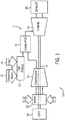
- FIG. 1 a block diagram of an embodiment of a turbine system 10 having a gas turbine engine 11 is illustrated.
- the turbine system 10 may use liquid or gaseous fuel, such as natural gas and/or a synthetic gas, to drive the turbine system 10.
- one or more fuel nozzles 12 intake a fuel supply 14.
- one or more fuel nozzles 12 may be used to intake liquid fuel and one or more other fuel nozzles 12 may be used to intake gaseous fuel.
- the fuel nozzles 12 may intake a deaerated water supply 15 when the turbine system 10 uses liquid fuel.
- the disclosed turbine system 10 mixes the liquid fuel with the deaerated water supply 15 upstream from and/or within the fuel nozzles 12.
- Mixing the liquid fuel with the deaerated water 15 may improve the combustion efficiency of the gas turbine engine 11 and/or reduce production of byproducts (e.g., NO x , SO x , CO, or particulate matter) from the gas turbine engine 11.
- the fuel nozzles 12 then partially mix the fuel, or the fuel-water mixture, with air, and distribute the fuel, water (when used), and air mixture into a combustor 16 where further mixing occurs between the fuel, water (when used), and air.
- the fuel nozzles 12 may be disposed inside the combustor 16.
- the fuel, water (when used), and air mixture combusts in a chamber within the combustor 16, thereby creating hot pressurized exhaust gases.
- the combustor 16 directs the exhaust gases through a turbine 18 toward an exhaust outlet 20.
- a plurality of combustors 16 may be arranged circumferentially about the gas turbine engine 11.
- Each of the plurality of combustors 16 may include separate fuel nozzles 12.
- the gases force turbine blades to rotate a shaft 22 along an axis of the turbine system 10.
- the shaft 22 is connected to various components of the turbine system 10, including a compressor 24.
- the compressor 24 also includes blades coupled to the shaft 22.
- the shaft 22 may also be connected to a load 28, which may be a vehicle or a stationary load, such as an electrical generator in a power plant or a propeller on an aircraft, for example.
- the load 28 may include any suitable device capable of being powered by the rotational output of turbine system 10.
- FIG. 2 illustrates a block diagram of a turbine fuel supply system 40 of the combustor 16 of the gas turbine engine 11, as illustrated in FIG. 1 .
- valve is used to refer to any device capable of operating as a flow control.
- a liquid fuel 42 may be supplied to the combustor 16.
- the liquid fuel 42 include, but are not limited to, hydrocarbon based liquid fuels, such as diesel fuel, jet fuel, gasoline, naphtha, fuel oil, and so forth.
- the liquid fuel 42 is routed to the combustor 16 via a liquid fuel flow path 44, which may include a liquid fuel supply valve 46.
- the liquid fuel flow path 44 may also include a liquid fuel manifold 48, which may be used to supply the liquid fuel 42 to a plurality of mixing assemblies 49 (as indicated by ellipses), which may be, for example, arranged circumferentially about the liquid fuel manifold 48.
- the liquid fuel manifold 48 may be configured as a ring with a circular or polygonal shape.
- Each of the plurality of mixing assemblies 49 may be coupled to one of the plurality of combustors 16 arranged circumferentially about the gas turbine engine 11.
- the liquid fuel supply valve 46 may be used to adjust and/or isolate flow of the liquid fuel 42 to the liquid fuel manifold 48.
- each mixing assembly 49 may include a liquid fuel mixing valve 50, which may be used to adjust a flow rate of the liquid fuel 42 to a liquid fuel mixer 52 disposed in each mixing assembly 49.
- a portion of the liquid fuel 42 may be routed to a pilot fuel flow path 54, which may include a pilot fuel supply valve 56.
- the pilot fuel flow path 54 may be used when first starting the combustor 16 with the liquid fuel 42.
- the pilot fuel flow path 54 may flow a lower flow rate of the liquid fuel 42 than the liquid fuel flow path 44.
- the flow rate of the liquid fuel 42 through the pilot fuel flow path 54 may be between approximately 5 percent to 50 percent, 10 percent to 35 percent, or 15 percent to 25 percent of a normal, or regular, flow rate.
- a low flow rate of the liquid fuel 42 which may be referred to as pilot fuel, may be used to first start the combustor 16.
- the liquid fuel flow path 44 may be used to supply the normal, or regular, flow rate of the liquid fuel 42 to the combustor 16.
- the liquid fuel 42 from the pilot fuel supply valve 56 may be routed to a pilot fuel manifold 60, which may be used to supply the pilot fuel to the plurality of mixing assemblies 49 (as indicated by ellipses).
- the pilot fuel manifold 60 may be configured as a ring with a circular or polygonal shape.
- the pilot fuel supply valve 56 may be used to adjust and/or isolate flow of the liquid fuel 42 to the pilot fuel manifold 60.
- the mixing assembly 49 may include a pilot fuel mixing valve 62, which may be used to adjust a flow rate of the liquid fuel 42 to a pilot fuel mixer 64 disposed in the mixing assembly 49.
- the pilot fuel flow path 54 may no longer be used to supply the liquid fuel 42 to the combustor 16.
- a gaseous fuel 66 may be supplied to the pilot fuel manifold 60 via a gaseous fuel flow path 67, thereby purging the liquid fuel 42 from the pilot fuel manifold 60 with the gaseous fuel 66.
- the gaseous fuel 66 include, but are not limited to, methane, natural gas, syngas, and so forth.
- the gaseous fuel flow path 67 may include a gaseous fuel supply valve 68, which may be used to adjust and/or isolate flow of the gaseous fuel 66. Purging the pilot fuel flow path 54 with the gaseous fuel 66 may help prevent the liquid fuel 42 from coking or oxidizing in the pilot fuel flow path 54 when not in use.
- other gases such as nitrogen, carbon dioxide, steam, and so forth, may be used to purge the pilot fuel flow path 54 when not in use.
- the deaerated water 15 may be supplied to the combustor 16 via a deaerated water flow path 70, which may include a deaerated water supply valve 72.
- Deaerated water may be generated by contacting water with steam to strip, or remove, dissolved gases from the water.
- the solubility of dissolved gases generally decreases at higher temperatures, so the high temperature of the steam helps to drive off the dissolved gases.
- a tray-type, or cascade-type, deaerator water flows downward through perforations formed one or more perforated trays and steam flows upward through the perforations.
- a spray-type deaerator water is sprayed downward into rising steam.
- the steam carries away the dissolved gases from the water to generate the deaerated water.
- Another method of generating the deaerated water 15 is vacuum degasification, in which water is placed under a reduced pressure (e.g., a vacuum) to reduce the solubility of the dissolved gases.
- Other methods of deaeration, such as membrane degasification, may also be used to generate the deaerated water 14.
- the deaerated water may include between approximately 5 parts per billion (ppb) by weight to 10 ppb by weight, 3 ppb by weight to 25 ppb by weight, or 1 ppb by weight to 50 ppb by weight of dissolved gases (e.g., oxygen or carbon dioxide).
- deaerated water 15 is boiler feedwater, which may be supplied by a water treatment system and used to supply a boiler to generate steam or hot water.
- the boiler feedwater may be treated by the water treatment system to help prevent corrosion and fouling in the boiler.
- Another source of the deaerated water 15 is a heat recovery steam generator, as discussed in detail below.
- the deaerated water supply valve 72 in the deaerated water flow path 70 may be used to adjust and/or isolate a flow of the deaerated water 15 to a deaerated water manifold 74, which may be used to supply the deaerated water 15 to the plurality of mixing assemblies 49 (as indicated by ellipses).
- the deaerated water manifold 74 may be configured as a ring with a circular or polygonal shape. As shown in FIG. 2 , the deaerated water 15 is supplied to the liquid fuel mixer 52 and the pilot fuel mixer 64 of each of the plurality of mixing assemblies 49.
- the mixing assembly 49 may include a deaerated water liquid fuel mixing valve 76 and a deaerated water pilot fuel mixing valve 78.
- the deaerated water liquid fuel mixing valve 76 and the deaerated water pilot fuel mixing valve 78 may adjust a flow of the deaerated water 15 to the liquid fuel mixer 52 and the pilot fuel mixer 64, respectively.
- the liquid fuel and pilot fuel mixers 52 and 64 may mix the liquid fuel 42 with the deaerated water 15 to form an emulsion, which may be defined as a mixture of two of more immiscible liquids.
- liquid fuel and pilot fuel mixers 52 and 64 examples include, but are not limited to, mixing tees, in-line mixers, static mixers, paddle mixers, blenders, ribbon blenders, and so forth.
- a mixing tee may include two pipes, or lines, coming together at a tee.
- Mixtures of the deaerated water 15 and the liquid fuel 42 form improved emulsions compared to mixtures of non-deaerated water and the liquid fuel 42 for several reasons.
- droplets of one liquid will be dispersed throughout the other liquid.
- droplets of the hydrocarbon liquid will initially be dispersed throughout the water.
- the droplets of the hydrocarbon are hydrophobic and will eventually coalesce to form a hydrocarbon phase separate from a water phase. Removal of dissolved gases from water to form deaerated water may enhance the ability of the hydrocarbon droplets to break away, or detach, from the hydrocarbon phase when mechanically disturbed.
- the liquid fuel mixer 52 or the pilot fuel mixer 64 may be used to mechanically disturb the mixture of the deaerated water 15 and the liquid fuel 42, e.g., a hydrocarbon based liquid fuel, to form a stable emulsion. Additionally, removal of dissolved gases from water may aid in the detachment of hydrocarbon droplets that would otherwise coalesce to form the hydrocarbon phase. In other words, the hydrophobic attraction of droplets of the liquid fuel 42 to one another in the deaerated water 15 may be reduced, thereby enhancing detachment of the droplets of the liquid fuel 42 and emulsion formation. Such emulsions of the deaerated water 15 and the liquid fuel 42 may be stable for extended periods, for example, up to several days or longer.
- the liquid fuel 42 e.g., a hydrocarbon based liquid fuel
- the mixture of the deaerated water 15 and the liquid fuel 42 may be expected to remain an emulsion, without separation, downstream of the liquid fuel mixer 52 and the pilot fuel mixer 64. Additionally, the mixture of the deaerated water 15 and the liquid fuel 42 may be stored for certain periods without separation. Further, emulsions of the deaerated water 15 and the liquid fuel 42 may be formed using only simple mechanical mixing, as with the liquid fuel mixer 52 or the pilot fuel mixer 64, without use of any additional additives, such as surfactants or polymer stabilizers. In such emulsions, the liquid fuel 42 may be more uniformly distributed in the deaerated water 15 compared to mixtures of the liquid fuel and water that is not deaerated. For example, sizes of the droplets of the liquid fuel 42 may be less than approximately 20 micrometers, 15 micrometers, 10 micrometers, 5 micrometers, or 1 micrometer.
- the emulsion of the liquid fuel 42 and the deaerated water 15 from the liquid fuel mixer 52 is supplied to main nozzles 80 of the combustor 16.
- the main nozzles 80 may constitute a portion of the fuel nozzles 12 and may discharge the emulsion at high, or normal, flow rates.
- the emulsion of the liquid fuel 42 and the deaerated water 15 from the pilot fuel mixer 64 is supplied to pilot nozzles 82 of the combustor 16.
- the pilot nozzles 82 may constitute another portion of the fuel nozzles 12 and may discharge the emulsion at low, or startup, flow rates.
- the pilot nozzles 82 may be used during startup of the combustor 16, after which the main nozzles 80 are used.
- the pilot nozzles 82 may be smaller than the main nozzles 80.
- the pilot nozzles 82 may be limited to passing lower flow rates of the emulsion compared to the main nozzles 80.
- the flow rate of the emulsion through the pilot nozzles 82 may be between approximately 5 percent to 50 percent, 10 percent to 35 percent, or 15 percent to 25 percent of a flow rate through the main nozzles 80.
- the pilot nozzles 82 may be used together with, or at the same time as, the main nozzles 80.
- the combustor 16 may include additional fuel nozzles 12 to supply the gaseous fuel 66.
- the turbine fuel supply system 40 may include a controller 84, which may send and/or receive various signals along signal paths 86.
- the signals sent or received along the signal paths 86 will also be referred to by the reference numeral 86.
- the controller 84 may send signals 86 to one or more of the liquid fuel supply valve 46, the liquid fuel mixing valve 50, the pilot fuel supply valve 56, the pilot fuel mixing valve 62, the gaseous fuel supply valve 68, the liquid fuel water mixing valve 76, and the pilot fuel water mixing valve 78 to direct the valves to adjust, open, or close.
- the controller 84 may receive a signal 86 from a NO x sensor 88 that senses a NO x concentration of the exhaust 20.
- the senor 88 may be configured to sense other parameters of the exhaust 20, such as, but not limited to, SO x concentration, CO concentration, particulate concentration, temperature, pressure, flow rate, and so forth.
- the controller 84 may adjust a ratio of the liquid fuel 42 to the deaerated water 15 if a sensed level of the NO x concentration from the NO x sensor 88 is above a threshold level of the NO x concentration.
- the controller 84 may send a signal 86 to the liquid fuel water mixing valve 76 and/or deaerated water pilot fuel mixing valve 78 to open more to enable additional deaerated water 15 to flow to the liquid fuel mixer 52 and/or the pilot fuel mixer 64, respectively.
- the ratio of the liquid fuel 42 to the deaerated water 15 decreases, thereby decreasing the NO x concentration of the exhaust 20.
- the ratio of the liquid fuel 42 to the deaerated water 15 may be, for example, between approximately 0.5:1 to 0.7:1, 0.4:1 to 0.8:1, or 0.3:1 to 1:1.
- the controller 84 may send a signal 86 to the liquid fuel water mixing valve 76 and/or deaerated water pilot fuel mixing valve 78 to close partially to reduce the flow of the deaerated water 15 to the liquid fuel mixer 52 and/or the pilot fuel mixer 64, respectively.
- the controller 84 may receive signals 86 from a deaerated water temperature sensor 90 and/or a deaerated water pressure sensor 92.
- the controller 84 may send signals 86 to the liquid fuel water mixing valve 76 or the pilot fuel water mixing valve 78 in response to signals 86 received from the deaerated water temperature sensor 90 and/or deaerated water pressure sensor 92. For example, if the temperature of the deaerated water 15 increases, the controller 84 may direct the liquid fuel water mixing valve 76 or the pilot fuel water mixing valve 78 to reduce the flow rate of deaerated water 15 to the combustor 16.
- the controller 84 may direct the liquid fuel water mixing valve 76 or the pilot fuel water mixing valve 78 to increase the flow rate of deaerated water 15 to the combustor 16.
- the controller 84 may adjust the temperature and/or pressure of the deaerated water 15 in response to signals 86 from the deaerated water temperature sensor 90 and/or deaerated water pressure sensor 92.
- the controller 84 may send a signal 86 to the source of the deaerated water 15 to maintain the deaerated water 15 at a temperature between approximately 100 degrees Celsius to 175 degrees Celsius, or 125 degrees Celsius to 150 degrees Celsius.
- the controller 84 may adjust the flow rate of deaerated water 15 to maintain a temperature of the emulsion by sending signals 86 to the deaerated water mixing valves 76 or 78.
- the controller 84 may adjust the flow rate of deaerated water 15 to maintain the emulsion at a temperature between approximately 75 degrees Celsius to 150 degrees Celsius, or 100 degrees Celsius to 125 degrees Celsius.
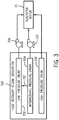
- FIG. 3 is a block diagram of a heat recovery steam generator (HRSG) 100 that may be used to supply the deaerated water 15.
- HRSG heat recovery steam generator
- GTCC gas turbine combined cycle
- heated exhaust gas from the gas turbine engine may be transported into the HRSG 100 and used to heat water to produce steam.
- other sources of heat may be used by the HRSG 100 to produce steam.
- the HRSG 100 may include one or more sections arranged in different configurations.
- the HRSG 100 may include a low-pressure steam section, an intermediate-pressure steam section, and a high-pressure steam section. Accordingly, each section of the HRSG 100 may include a steam drum.
- the HRSG 100 may include a low-pressure drum 102, an intermediate-pressure drum 104, and a high-pressure drum 106.
- Each of the drums 102, 104, and 106 may be used to separate steam from condensate in the respective sections of the HRSG 100.
- condensate may flow from the bottom of the steam drum and steam may flow from the top of the steam drum.
- other types of heat exchangers may be used to supply the deaerated water 15. Such exchangers may be found in a variety of plants other than the GTCC power plant.
- the HRSG 100 is supplied with deaerated water from a deaerating condenser to help prevent corrosion inside the HRSG 100.
- deaerating condensers include, but are not limited to, tray-type deaerators and spray-type deaerators.
- heat from the heated exhaust gas, or any other source of heat converts the deaerated water into steam, which forms deaerated water again when condensed and collected in the drums 102, 104, and 106.
- a portion of the condensate from the drums 102, 104 and 106 may be supplied to the turbine fuel supply system 40 as deaerated water 15.
- the HRSG 100 already include the deaerating condenser, no additional deaerator is used to supply the deaerated water 15 to the turbine fuel supply system 40. Instead, a portion of deaerated water already produced by the HRSG 100 is used to supply the deaerated water 15 to the turbine fuel supply system 40. Thus, additional equipment, costs, and complexity associated with a separate deaerator for the turbine fuel supply system 40 may be avoided by using a portion of the deaerated water from the HRSG 100 as the deaerated water 15 to the turbine fuel supply system 40. In plants other than the GTCC power plant, other heat exchangers, or similar equipment, may be available to produce the deaerated water 15 supplied to the turbine fuel supply system 40. In further embodiments, deaerators using tray-type condensers, spray-type condensers, or other techniques may be used to supply the deaerated water 15.
- the liquid fuel 42 may be supplied to the combustor 16 at a high pressure to provide for efficient combustion.
- the pressure of the liquid fuel 42 may be between approximately 8000 kilopascals (kPa) to 10000 kPa, 8400 kPa to 9600 kPa, or 8800 kPa to 9200 kPa.
- the deaerated water 15 may be supplied to the liquid fuel and pilot fuel mixers 52 and 64 at similar or higher pressures to enable the deaerated water 15 to mix properly with the liquid fuel 42.
- a pressure of the deaerated water 15 from the high-pressure drum 106 may be between approximately 11000 kPa to 20000 kPa, 14000 kPa to 18000 kPa, or 16000 kPa to 17000 kPa.
- the deaerated water 15 from the high-pressure drum 106 may be supplied directly to the deaerated water manifold 74.
- a pressure of the deaerated water 15 from the low-pressure drum 102 or the intermediate pressure drum 104 which may be limited by the configuration of the HRSG 100, may be less than that of the liquid fuel 42.
- a pressure of the deaerated water 15 from the intermediate-pressure drum 104 may be between approximately 4700 kPa to 8000 kPa, 5500 kPa to 7500 kPa, or 6000 kPa to 7000 kPa.
- a pressure of the deaerated water 15 from the low-pressure drum 102 may be between approximately 2000 kPa to 2760 kPa, 1400 kPa to 4120 kPa, or 680 kPa to 5600 kPa.
- a first booster pump 108 may be used to increase the pressure of the deaerated water 15 from the low-pressure drum 102 to a pressure closer to that of the liquid fuel 42.
- a second booster pump 110 may be used to increase the pressure of the deaerated water 15 from the intermediate pressure drum 104 to a pressure closer to that of the liquid fuel 42.
- the pressure of the deaerated water 15 from the intermediate pressure drum 104 may be close enough to the pressure of the liquid fuel 42 to omit the second booster pump 110.
- a portion 112 of the intermediate pressure condensate may be routed from the intermediate pressure drum 104 to the low-pressure drum 102, thereby omitting the second booster pump 110.
Landscapes
- Engineering & Computer Science (AREA)
- Chemical & Material Sciences (AREA)
- Combustion & Propulsion (AREA)
- Mechanical Engineering (AREA)
- General Engineering & Computer Science (AREA)
- Feeding And Controlling Fuel (AREA)
- Engine Equipment That Uses Special Cycles (AREA)
Claims (15)
- System, umfassend:Brennkammer (16) für ein Gasturbinentriebwerk (10), umfassend Kraftstoffdüsen (12) zum Mischen eines ersten Kraftstoffgemischs mit Luft zum Verbrennen des Kraftstoff-Luft-Gemischs in einer Kammer innerhalb der Brennkammer (16),ein Turbinenkraftstoffversorgungssystem (40), umfassend:einen ersten Turbinenkraftstoffmischer (52), der konfiguriert ist, einen ersten Flüssigkraftstoff (42) und ein erstes entlüftetes Wasser (15) zu mischen, um das erste Kraftstoffgemisch zu erzeugen, wobei das erste Kraftstoffgemisch konfiguriert ist, um in der Brennkammer (16) zu verbrennen;einen Strömungsweg für entlüftetes Wasser (70), der konfiguriert ist, das erste entlüftete Wasser (15) zu dem ersten Turbinenkraftstoffmischer (52) zu leiten; undeinen Flüssigkraftstoffströmungsweg (44), der konfiguriert ist, den ersten Flüssigkraftstoff (42) zu dem ersten Turbinenkraftstoffmischer (52) zu leiten,gekennzeichnet durch einen Entlüfter zum Erzeugen des entlüfteten Wassers.
- System nach Anspruch 1, wobei der erste Turbinenkraftstoffmischer (52) mindestens eines von einem Misch-T-Stück, einem Inline-Mischer, einem statischen Mischer, einem Paddelmischer, einem Mixer oder einem Bandmischer oder einer Kombination davon umfasst.
- System nach Anspruch 1 oder Anspruch 2, umfassend ein Wasserbehandlungssystem (72, 74), das konfiguriert ist, das erste entlüftete Wasser (15) dem ersten Turbinenkraftstoffmischer (52) entlang des Strömungswegs (70) für entlüftetes Wasser zuzuführen.
- System nach einem der Ansprüche 1 bis 3, umfassend einen Wärmerückgewinnungsdampferzeuger, der konfiguriert ist, das erste entlüftete Wasser (15) dem ersten Turbinenkraftstoffmischer (52) entlang des Strömungswegs für entlüftetes Wasser (70) zuzuführen.
- System nach Anspruch 4, wobei der Wärmerückgewinnungsdampferzeuger (100) konfiguriert ist, das erste entlüftete Wasser (15) zu erzeugen.
- System nach Anspruch 4 oder Anspruch 5, umfassend eine Boosterpumpe (108), die konfiguriert ist, einen Druck des ersten entlüfteten Wassers (15) aus einem Niederdruckabschnitt (102) oder einem Mitteldruckabschnitt (104) des Wärmerückgewinnungsdampferzeugers (100) zu erhöhen.
- System nach einem der vorstehenden Ansprüche, wobei der erste Turbinenkraftstoffmischer (52) konfiguriert ist, den ersten Flüssigkraftstoff (42) und das erste entlüftete Wasser (15) zu mischen, um eine erste Emulsion des ersten Flüssigkraftstoffs (42) und des ersten entlüfteten Wassers (15) als das erste Kraftstoffgemisch zu erzeugen.
- System nach einem der vorstehenden Ansprüche, umfassend:
einen zweiten Turbinenkraftstoffmischer (64), der konfiguriert ist, einen zweiten Flüssigkraftstoff (66) und ein zweites entlüftetes Wasser zu mischen, um ein zweites Kraftstoffgemisch zu erzeugen, wobei das zweite Kraftstoffgemisch konfiguriert ist, in der Brennkammer (16) des Gasturbinentriebwerks (10) zu verbrennen, wobei das erste Kraftstoffgemisch ein Pilotkraftstoffgemisch ist und das zweite Kraftstoffgemisch ein Hauptkraftstoffgemisch ist. - System nach einem der vorstehenden Ansprüche, wobei der Strömungsweg für entlüftetes Wasser (70) einen Verteiler für entlüftetes Wasser (74) umfasst, der konfiguriert ist, das erste entlüftete Wasser zu einer Vielzahl von Mischanordnungen (49) des Gasturbinentriebwerks zu leiten.
- System nach Anspruch 9, wobei jede der Vielzahl von Mischanordnungen (49) einen von einer Vielzahl der ersten Turbinenkraftstoffmischer (52), eines von einer Vielzahl von entlüfteten Wassermischventilen (72) und eines von einer Vielzahl von Flüssigkraftstoffmischventilen (50) umfasst.
- System nach einem der vorstehenden Ansprüche, ferner umfassend:einen Nebenproduktsensor (88), der konfiguriert ist, ein Eingangssignal (86) zu übertragen, das eine erfasste Nebenproduktkonzentration in einem Abgas aus einem Gasturbinentriebwerk (10) anzeigt; undeine Nebenproduktsteuerung (84), die konfiguriert ist, das Eingangssignal (86) von dem Nebenproduktsensor (88) zu empfangen und ein Ausgangssignal (86) an das Turbinenkraftstoffversorgungssystem (40) zu übertragen, wobei das Turbinenkraftstoffversorgungssystem (40) auf das Ausgangssignal (86) reagiert, um ein Kraftstoff-Wasser-Verhältnis in dem Gemisch aus dem Flüssigkraftstoff (42) und einem entlüfteten Wasser (15) einzustellen, wenn die erfasste Nebenproduktkonzentration über einem Schwellenwert liegt.
- System nach Anspruch 11, wobei das Nebenprodukt mindestens eines von Stickstoffoxid (NOx), Schwefeloxid (SOx), Kohlenmonoxid oder teilchenförmigem Material oder eine Kombination davon umfasst.
- Verfahren, umfassend:Zuführen eines Flüssigkraftstoffs (42) zu einem Mischer (52);Zuführen eines entlüfteten Wassers (15) zu dem Mischer (52);Mischen des Flüssigkraftstoffs (42) mit dem entlüfteten Wasser (15) unter Verwendung des Mischers (52), um ein Gemisch des Flüssigkraftstoffs (42) und des entlüfteten Wassers (15) zu erzeugen; undZuführen des Gemischs aus dem Flüssigkraftstoff (42) und dem entlüfteten Wasser (15) zu einer Brennkammer eines Gasturbinentriebwerks (10),wobei die Brennkammer (16) das Gemisch aus dem Flüssigkraftstoff (42) und dem entlüfteten Wasser (15) mit Luft unter Verwendung von Kraftstoffdüsen (12) mischt, um das Kraftstoff-Luft-Gemisch in einer Kammer innerhalb der Brennkammer (16) zu verbrennen.
- Verfahren nach Anspruch 13, umfassend das Einstellen eines Verhältnisses des Flüssigkraftstoffs (42) zu dem entlüfteten Wasser (15) in dem Gemisch oder Einstellen einer Temperatur oder eines Drucks des entlüfteten Wassers (15), um eine Nebenproduktkonzentration in Produkten zu steuern, die aus der Verbrennung des Gemischs resultieren.
- Verfahren nach Anspruch 13 oder 14, wobei das Mischen des Flüssigkraftstoffs (42) mit dem entlüfteten Wasser (15) das Verwenden des Mischers (52) umfasst, um eine Emulsion des Flüssigkraftstoffs (42) und des entlüfteten Wassers (15) zu erzeugen.
Applications Claiming Priority (1)
| Application Number | Priority Date | Filing Date | Title |
|---|---|---|---|
| US13/280,237 US9267433B2 (en) | 2011-10-24 | 2011-10-24 | System and method for turbine combustor fuel assembly |
Publications (3)
| Publication Number | Publication Date |
|---|---|
| EP2587022A2 EP2587022A2 (de) | 2013-05-01 |
| EP2587022A3 EP2587022A3 (de) | 2017-11-01 |
| EP2587022B1 true EP2587022B1 (de) | 2021-02-24 |
Family
ID=47142932
Family Applications (1)
| Application Number | Title | Priority Date | Filing Date |
|---|---|---|---|
| EP12189163.4A Active EP2587022B1 (de) | 2011-10-24 | 2012-10-19 | System mit einer Kraftstoffzufuhr der Turbine und verwandtes Verfahren |
Country Status (3)
| Country | Link |
|---|---|
| US (1) | US9267433B2 (de) |
| EP (1) | EP2587022B1 (de) |
| CN (1) | CN103062801B (de) |
Families Citing this family (19)
| Publication number | Priority date | Publication date | Assignee | Title |
|---|---|---|---|---|
| US9243804B2 (en) | 2011-10-24 | 2016-01-26 | General Electric Company | System for turbine combustor fuel mixing |
| US9650955B2 (en) * | 2011-11-10 | 2017-05-16 | General Electric Company | System for purging gas fuel circuit for a gas turbine engine |
| US20150020530A1 (en) * | 2013-07-18 | 2015-01-22 | General Electric Company | Gas turbine emissions control system and method |
| US20150020529A1 (en) * | 2013-07-18 | 2015-01-22 | General Electric Company | Gas turbine emissions control system and method |
| US20150075450A1 (en) * | 2013-09-13 | 2015-03-19 | Uop Llc | Heat recovery from a high pressure stream |
| US9863322B2 (en) * | 2014-01-23 | 2018-01-09 | United Technologies Corporation | Selectively deoxygenated stored fuel system |
| WO2017002076A1 (en) * | 2015-06-30 | 2017-01-05 | Ansaldo Energia Ip Uk Limited | Gas turbine control system |
| US10035609B2 (en) * | 2016-03-08 | 2018-07-31 | Harris Corporation | Wireless engine monitoring system for environmental emission control and aircraft networking |
| US10378447B2 (en) | 2016-09-30 | 2019-08-13 | General Electric Company | System and method for purging fuel or coolant from turbomachine |
| US10634358B2 (en) * | 2017-06-16 | 2020-04-28 | General Electric Company | System and method for igniting liquid fuel in a gas turbine combustor |
| EP3421761B1 (de) * | 2017-06-30 | 2020-11-25 | Ansaldo Energia IP UK Limited | Sekundäre brennkammer für eine sequentielle gasturbinenbrennkammer |
| WO2020242556A1 (en) * | 2019-05-30 | 2020-12-03 | Siemens Aktiengesellschaft | Gas turbine water injection for emissions reduction |
| EP3875742A1 (de) * | 2020-03-04 | 2021-09-08 | Rolls-Royce plc | Gestufte verbrennung |
| US11326521B2 (en) | 2020-06-30 | 2022-05-10 | General Electric Company | Methods of igniting liquid fuel in a turbomachine |
| US11306661B1 (en) | 2020-12-04 | 2022-04-19 | General Electric Company | Methods and apparatus to operate a gas turbine engine with hydrogen gas |
| EP4134531B1 (de) * | 2021-08-12 | 2024-11-06 | General Electric Technology GmbH | Gasturbinenmotor mit wasser-brennstoff-emulsionen und verfahren |
| US11898491B1 (en) * | 2022-07-21 | 2024-02-13 | Rtx Corporation | Water pressure and quantity monitoring for hydrogen steam injected and inter-cooled turbine engine |
| US11933217B2 (en) | 2022-07-21 | 2024-03-19 | Rtx Corporation | Water condition monitoring for hydrogen steam injected and inter-cooled turbine engine |
| WO2024054836A1 (en) * | 2022-09-06 | 2024-03-14 | Vericor Power Systems Llc | Purge system for a dual-fuel turbine engine |
Family Cites Families (46)
| Publication number | Priority date | Publication date | Assignee | Title |
|---|---|---|---|---|
| US4110973A (en) * | 1977-01-24 | 1978-09-05 | Energy Services Inc. | Water injection system for industrial gas turbine engine |
| US4418543A (en) | 1980-12-02 | 1983-12-06 | United Technologies Corporation | Fuel nozzle for gas turbine engine |
| US4798330A (en) | 1986-02-14 | 1989-01-17 | Fuel Systems Textron Inc. | Reduced coking of fuel nozzles |
| US4993918A (en) | 1989-05-19 | 1991-02-19 | United Technologies Corporation | Replaceable fairing for a turbine exhaust case |
| US5175994A (en) * | 1991-05-03 | 1993-01-05 | United Technologies Corporation | Combustion section supply system having fuel and water injection for a rotary machine |
| US5298091A (en) | 1991-12-20 | 1994-03-29 | United Technologies Corporation | Inhibiting coke formation by heat treating in nitrogen atmosphere |
| US5240741A (en) | 1991-12-20 | 1993-08-31 | United Technologies Corporation | Inhibiting coke formation by coating gas turbine elements with tungsten disulfide |
| US5324544A (en) | 1991-12-20 | 1994-06-28 | United Technologies Corporation | Inhibiting coke formation by coating gas turbine elements with alumina-silica sol gel |
| US5307619A (en) * | 1992-09-15 | 1994-05-03 | Westinghouse Electric Corp. | Automatic NOx control for a gas turbine |
| US6289666B1 (en) | 1992-10-27 | 2001-09-18 | Ginter Vast Corporation | High efficiency low pollution hybrid Brayton cycle combustor |
| US6564556B2 (en) * | 1992-10-27 | 2003-05-20 | J. Lyell Ginter | High efficiency low pollution hybrid brayton cycle combustor |
| US5448890A (en) | 1994-03-24 | 1995-09-12 | United Technologies Corporation | Fuel supply apparatus with cooled check valve |
| US5809771A (en) | 1996-01-19 | 1998-09-22 | Woodward Governor Company | Aircraft engine fuel system |
| US6145294A (en) | 1998-04-09 | 2000-11-14 | General Electric Co. | Liquid fuel and water injection purge system for a gas turbine |
| US6125624A (en) | 1998-04-17 | 2000-10-03 | Pratt & Whitney Canada Corp. | Anti-coking fuel injector purging device |
| EP0952317A3 (de) | 1998-04-21 | 2002-04-17 | Mitsubishi Heavy Industries, Ltd. | Spülsystem für die Kraftstoffzufuhr einer Gasturbine |
| US6092363A (en) * | 1998-06-19 | 2000-07-25 | Siemens Westinghouse Power Corporation | Low Nox combustor having dual fuel injection system |
| US6125627A (en) | 1998-08-11 | 2000-10-03 | Allison Advanced Development Company | Method and apparatus for spraying fuel within a gas turbine engine |
| US6367239B1 (en) * | 1998-12-09 | 2002-04-09 | General Electric Company | Fuel delivery systems and method |
| US6598383B1 (en) | 1999-12-08 | 2003-07-29 | General Electric Co. | Fuel system configuration and method for staging fuel for gas turbines utilizing both gaseous and liquid fuels |
| US6315815B1 (en) | 1999-12-16 | 2001-11-13 | United Technologies Corporation | Membrane based fuel deoxygenator |
| US6457316B1 (en) | 2000-10-05 | 2002-10-01 | General Electric Company | Methods and apparatus for swirling fuel within fuel nozzles |
| US6438938B1 (en) | 2000-11-28 | 2002-08-27 | Rolls-Royce Corporation | Bearing compartment self cooling vent system |
| US6427447B1 (en) | 2001-02-06 | 2002-08-06 | United Technologies Corporation | Bulkhead for dual fuel industrial and aeroengine gas turbines |
| US20020144664A1 (en) * | 2001-04-09 | 2002-10-10 | Supercritical Combustion Corporation | Heating of fuels |
| US6712080B1 (en) | 2002-02-15 | 2004-03-30 | The United States Of America As Represented By The Secretary Of The Army | Flushing system for removing lubricant coking in gas turbine bearings |
| US6886324B1 (en) | 2002-02-15 | 2005-05-03 | The United States Of America As Represented By The Secretary Of The Army | Apparatus for reducing coking in gas turbine bearings |
| US6915638B2 (en) | 2002-03-28 | 2005-07-12 | Parker-Hannifin Corporation | Nozzle with fluted tube |
| US6848260B2 (en) | 2002-09-23 | 2005-02-01 | Siemens Westinghouse Power Corporation | Premixed pilot burner for a combustion turbine engine |
| US6931853B2 (en) | 2002-11-19 | 2005-08-23 | Siemens Westinghouse Power Corporation | Gas turbine combustor having staged burners with dissimilar mixing passage geometries |
| US7117675B2 (en) | 2002-12-03 | 2006-10-10 | General Electric Company | Cooling of liquid fuel components to eliminate coking |
| US6918255B2 (en) | 2002-12-03 | 2005-07-19 | General Electric Company | Cooling of liquid fuel components to eliminate coking |
| JP2006523294A (ja) * | 2003-01-22 | 2006-10-12 | ヴァスト・パワー・システムズ・インコーポレーテッド | 反応装置 |
| US7007476B2 (en) | 2003-04-11 | 2006-03-07 | Parker-Hannifin Corporation | Gas turbine fuel system staging valves |
| US6935116B2 (en) | 2003-04-28 | 2005-08-30 | Power Systems Mfg., Llc | Flamesheet combustor |
| US6986254B2 (en) | 2003-05-14 | 2006-01-17 | Power Systems Mfg, Llc | Method of operating a flamesheet combustor |
| GB0329626D0 (en) | 2003-12-23 | 2004-01-28 | Goodrich Control Sys Ltd | Fuel system |
| US7104070B2 (en) | 2004-03-04 | 2006-09-12 | General Electric Company | Liquid fuel nozzle apparatus with passive water injection purge |
| US7137256B1 (en) | 2005-02-28 | 2006-11-21 | Peter Stuttaford | Method of operating a combustion system for increased turndown capability |
| US7640724B2 (en) | 2006-01-25 | 2010-01-05 | Siemens Energy, Inc. | System and method for improving the heat rate of a turbine |
| FR2903450B1 (fr) | 2006-07-07 | 2013-03-01 | Snecma | Procede de traitement des rejets d'huile dans un moteur a turbine a gaz |
| US20080115500A1 (en) * | 2006-11-15 | 2008-05-22 | Scott Macadam | Combustion of water borne fuels in an oxy-combustion gas generator |
| US8397509B2 (en) * | 2007-06-06 | 2013-03-19 | Herng Shinn Hwang | Catalytic engine |
| CN201103885Y (zh) | 2007-07-13 | 2008-08-20 | 济南钢铁股份有限公司 | 一种烧结余热发电除氧器用蒸汽发生装置 |
| US20090165435A1 (en) | 2008-01-02 | 2009-07-02 | Michal Koranek | Dual fuel can combustor with automatic liquid fuel purge |
| US8820087B2 (en) | 2008-09-08 | 2014-09-02 | Siemens Energy, Inc. | Method and system for controlling fuel to a dual stage nozzle |
-
2011
- 2011-10-24 US US13/280,237 patent/US9267433B2/en active Active
-
2012
- 2012-10-19 EP EP12189163.4A patent/EP2587022B1/de active Active
- 2012-10-24 CN CN201210410484.8A patent/CN103062801B/zh active Active
Non-Patent Citations (1)
| Title |
|---|
| None * |
Also Published As
| Publication number | Publication date |
|---|---|
| EP2587022A2 (de) | 2013-05-01 |
| US20130098056A1 (en) | 2013-04-25 |
| CN103062801B (zh) | 2017-03-01 |
| US9267433B2 (en) | 2016-02-23 |
| EP2587022A3 (de) | 2017-11-01 |
| CN103062801A (zh) | 2013-04-24 |
Similar Documents
| Publication | Publication Date | Title |
|---|---|---|
| US9267433B2 (en) | System and method for turbine combustor fuel assembly | |
| EP2587151B1 (de) | System zur Turbinenbrennkammerbrennstoffmischung | |
| EP2587160B1 (de) | System zur Turbinenbrennkammerbrennstoffmischung | |
| JP5314938B2 (ja) | 排気ガス再循環を備えた発電用システム及び方法 | |
| JP6309964B2 (ja) | 化学量論的排気ガス再循環ガスタービンシステム内の拡散燃焼を用いた負荷制御のためのシステム及び方法 | |
| JP6315713B2 (ja) | 化学量論的排気ガス再循環ガスタービンシステム内の燃料−希釈剤混合を用いた拡散燃焼のためのシステム及び方法 | |
| CN105637206B (zh) | 用于排放来自燃气涡轮发动机的燃烧气体的系统和方法 | |
| CN104769255B (zh) | 用于化学计量排气再循环燃气涡轮机系统的系统和方法 | |
| CN106062340B (zh) | 用于燃气涡轮发动机的系统和方法 | |
| JP2019031979A (ja) | 量論的排気ガス再循環ガスタービンシステムにおける酸化剤圧縮のためのシステム及び方法 | |
| EP2587023B1 (de) | Brennkammeranordnung einer Turbine | |
| CN120265870A (zh) | 用于nh3调节的燃气轮机辅助系统 |
Legal Events
| Date | Code | Title | Description |
|---|---|---|---|
| PUAI | Public reference made under article 153(3) epc to a published international application that has entered the european phase |
Free format text: ORIGINAL CODE: 0009012 |
|
| AK | Designated contracting states |
Kind code of ref document: A2 Designated state(s): AL AT BE BG CH CY CZ DE DK EE ES FI FR GB GR HR HU IE IS IT LI LT LU LV MC MK MT NL NO PL PT RO RS SE SI SK SM TR |
|
| AX | Request for extension of the european patent |
Extension state: BA ME |
|
| PUAL | Search report despatched |
Free format text: ORIGINAL CODE: 0009013 |
|
| AK | Designated contracting states |
Kind code of ref document: A3 Designated state(s): AL AT BE BG CH CY CZ DE DK EE ES FI FR GB GR HR HU IE IS IT LI LT LU LV MC MK MT NL NO PL PT RO RS SE SI SK SM TR |
|
| AX | Request for extension of the european patent |
Extension state: BA ME |
|
| RIC1 | Information provided on ipc code assigned before grant |
Ipc: F02C 3/30 20060101AFI20170926BHEP |
|
| STAA | Information on the status of an ep patent application or granted ep patent |
Free format text: STATUS: REQUEST FOR EXAMINATION WAS MADE |
|
| 17P | Request for examination filed |
Effective date: 20180502 |
|
| RBV | Designated contracting states (corrected) |
Designated state(s): AL AT BE BG CH CY CZ DE DK EE ES FI FR GB GR HR HU IE IS IT LI LT LU LV MC MK MT NL NO PL PT RO RS SE SI SK SM TR |
|
| STAA | Information on the status of an ep patent application or granted ep patent |
Free format text: STATUS: EXAMINATION IS IN PROGRESS |
|
| 17Q | First examination report despatched |
Effective date: 20190212 |
|
| GRAP | Despatch of communication of intention to grant a patent |
Free format text: ORIGINAL CODE: EPIDOSNIGR1 |
|
| STAA | Information on the status of an ep patent application or granted ep patent |
Free format text: STATUS: GRANT OF PATENT IS INTENDED |
|
| INTG | Intention to grant announced |
Effective date: 20200428 |
|
| GRAJ | Information related to disapproval of communication of intention to grant by the applicant or resumption of examination proceedings by the epo deleted |
Free format text: ORIGINAL CODE: EPIDOSDIGR1 |
|
| STAA | Information on the status of an ep patent application or granted ep patent |
Free format text: STATUS: EXAMINATION IS IN PROGRESS |
|
| GRAP | Despatch of communication of intention to grant a patent |
Free format text: ORIGINAL CODE: EPIDOSNIGR1 |
|
| STAA | Information on the status of an ep patent application or granted ep patent |
Free format text: STATUS: GRANT OF PATENT IS INTENDED |
|
| INTC | Intention to grant announced (deleted) | ||
| INTG | Intention to grant announced |
Effective date: 20201002 |
|
| GRAS | Grant fee paid |
Free format text: ORIGINAL CODE: EPIDOSNIGR3 |
|
| GRAA | (expected) grant |
Free format text: ORIGINAL CODE: 0009210 |
|
| STAA | Information on the status of an ep patent application or granted ep patent |
Free format text: STATUS: THE PATENT HAS BEEN GRANTED |
|
| AK | Designated contracting states |
Kind code of ref document: B1 Designated state(s): AL AT BE BG CH CY CZ DE DK EE ES FI FR GB GR HR HU IE IS IT LI LT LU LV MC MK MT NL NO PL PT RO RS SE SI SK SM TR |
|
| REG | Reference to a national code |
Ref country code: GB Ref legal event code: FG4D |
|
| REG | Reference to a national code |
Ref country code: CH Ref legal event code: EP |
|
| REG | Reference to a national code |
Ref country code: AT Ref legal event code: REF Ref document number: 1364711 Country of ref document: AT Kind code of ref document: T Effective date: 20210315 |
|
| REG | Reference to a national code |
Ref country code: IE Ref legal event code: FG4D |
|
| REG | Reference to a national code |
Ref country code: DE Ref legal event code: R096 Ref document number: 602012074479 Country of ref document: DE |
|
| REG | Reference to a national code |
Ref country code: LT Ref legal event code: MG9D |
|
| REG | Reference to a national code |
Ref country code: NL Ref legal event code: MP Effective date: 20210224 |
|
| PG25 | Lapsed in a contracting state [announced via postgrant information from national office to epo] |
Ref country code: LT Free format text: LAPSE BECAUSE OF FAILURE TO SUBMIT A TRANSLATION OF THE DESCRIPTION OR TO PAY THE FEE WITHIN THE PRESCRIBED TIME-LIMIT Effective date: 20210224 Ref country code: PT Free format text: LAPSE BECAUSE OF FAILURE TO SUBMIT A TRANSLATION OF THE DESCRIPTION OR TO PAY THE FEE WITHIN THE PRESCRIBED TIME-LIMIT Effective date: 20210624 Ref country code: HR Free format text: LAPSE BECAUSE OF FAILURE TO SUBMIT A TRANSLATION OF THE DESCRIPTION OR TO PAY THE FEE WITHIN THE PRESCRIBED TIME-LIMIT Effective date: 20210224 Ref country code: FI Free format text: LAPSE BECAUSE OF FAILURE TO SUBMIT A TRANSLATION OF THE DESCRIPTION OR TO PAY THE FEE WITHIN THE PRESCRIBED TIME-LIMIT Effective date: 20210224 Ref country code: GR Free format text: LAPSE BECAUSE OF FAILURE TO SUBMIT A TRANSLATION OF THE DESCRIPTION OR TO PAY THE FEE WITHIN THE PRESCRIBED TIME-LIMIT Effective date: 20210525 Ref country code: BG Free format text: LAPSE BECAUSE OF FAILURE TO SUBMIT A TRANSLATION OF THE DESCRIPTION OR TO PAY THE FEE WITHIN THE PRESCRIBED TIME-LIMIT Effective date: 20210524 Ref country code: NO Free format text: LAPSE BECAUSE OF FAILURE TO SUBMIT A TRANSLATION OF THE DESCRIPTION OR TO PAY THE FEE WITHIN THE PRESCRIBED TIME-LIMIT Effective date: 20210524 |
|
| REG | Reference to a national code |
Ref country code: AT Ref legal event code: MK05 Ref document number: 1364711 Country of ref document: AT Kind code of ref document: T Effective date: 20210224 |
|
| PG25 | Lapsed in a contracting state [announced via postgrant information from national office to epo] |
Ref country code: SE Free format text: LAPSE BECAUSE OF FAILURE TO SUBMIT A TRANSLATION OF THE DESCRIPTION OR TO PAY THE FEE WITHIN THE PRESCRIBED TIME-LIMIT Effective date: 20210224 Ref country code: LV Free format text: LAPSE BECAUSE OF FAILURE TO SUBMIT A TRANSLATION OF THE DESCRIPTION OR TO PAY THE FEE WITHIN THE PRESCRIBED TIME-LIMIT Effective date: 20210224 Ref country code: NL Free format text: LAPSE BECAUSE OF FAILURE TO SUBMIT A TRANSLATION OF THE DESCRIPTION OR TO PAY THE FEE WITHIN THE PRESCRIBED TIME-LIMIT Effective date: 20210224 Ref country code: RS Free format text: LAPSE BECAUSE OF FAILURE TO SUBMIT A TRANSLATION OF THE DESCRIPTION OR TO PAY THE FEE WITHIN THE PRESCRIBED TIME-LIMIT Effective date: 20210224 Ref country code: PL Free format text: LAPSE BECAUSE OF FAILURE TO SUBMIT A TRANSLATION OF THE DESCRIPTION OR TO PAY THE FEE WITHIN THE PRESCRIBED TIME-LIMIT Effective date: 20210224 |
|
| PG25 | Lapsed in a contracting state [announced via postgrant information from national office to epo] |
Ref country code: IS Free format text: LAPSE BECAUSE OF FAILURE TO SUBMIT A TRANSLATION OF THE DESCRIPTION OR TO PAY THE FEE WITHIN THE PRESCRIBED TIME-LIMIT Effective date: 20210624 |
|
| PG25 | Lapsed in a contracting state [announced via postgrant information from national office to epo] |
Ref country code: AT Free format text: LAPSE BECAUSE OF FAILURE TO SUBMIT A TRANSLATION OF THE DESCRIPTION OR TO PAY THE FEE WITHIN THE PRESCRIBED TIME-LIMIT Effective date: 20210224 Ref country code: SM Free format text: LAPSE BECAUSE OF FAILURE TO SUBMIT A TRANSLATION OF THE DESCRIPTION OR TO PAY THE FEE WITHIN THE PRESCRIBED TIME-LIMIT Effective date: 20210224 Ref country code: EE Free format text: LAPSE BECAUSE OF FAILURE TO SUBMIT A TRANSLATION OF THE DESCRIPTION OR TO PAY THE FEE WITHIN THE PRESCRIBED TIME-LIMIT Effective date: 20210224 Ref country code: CZ Free format text: LAPSE BECAUSE OF FAILURE TO SUBMIT A TRANSLATION OF THE DESCRIPTION OR TO PAY THE FEE WITHIN THE PRESCRIBED TIME-LIMIT Effective date: 20210224 |
|
| REG | Reference to a national code |
Ref country code: DE Ref legal event code: R097 Ref document number: 602012074479 Country of ref document: DE |
|
| PG25 | Lapsed in a contracting state [announced via postgrant information from national office to epo] |
Ref country code: ES Free format text: LAPSE BECAUSE OF FAILURE TO SUBMIT A TRANSLATION OF THE DESCRIPTION OR TO PAY THE FEE WITHIN THE PRESCRIBED TIME-LIMIT Effective date: 20210224 Ref country code: DK Free format text: LAPSE BECAUSE OF FAILURE TO SUBMIT A TRANSLATION OF THE DESCRIPTION OR TO PAY THE FEE WITHIN THE PRESCRIBED TIME-LIMIT Effective date: 20210224 Ref country code: SK Free format text: LAPSE BECAUSE OF FAILURE TO SUBMIT A TRANSLATION OF THE DESCRIPTION OR TO PAY THE FEE WITHIN THE PRESCRIBED TIME-LIMIT Effective date: 20210224 Ref country code: RO Free format text: LAPSE BECAUSE OF FAILURE TO SUBMIT A TRANSLATION OF THE DESCRIPTION OR TO PAY THE FEE WITHIN THE PRESCRIBED TIME-LIMIT Effective date: 20210224 |
|
| PLBE | No opposition filed within time limit |
Free format text: ORIGINAL CODE: 0009261 |
|
| STAA | Information on the status of an ep patent application or granted ep patent |
Free format text: STATUS: NO OPPOSITION FILED WITHIN TIME LIMIT |
|
| PG25 | Lapsed in a contracting state [announced via postgrant information from national office to epo] |
Ref country code: AL Free format text: LAPSE BECAUSE OF FAILURE TO SUBMIT A TRANSLATION OF THE DESCRIPTION OR TO PAY THE FEE WITHIN THE PRESCRIBED TIME-LIMIT Effective date: 20210224 |
|
| 26N | No opposition filed |
Effective date: 20211125 |
|
| PG25 | Lapsed in a contracting state [announced via postgrant information from national office to epo] |
Ref country code: SI Free format text: LAPSE BECAUSE OF FAILURE TO SUBMIT A TRANSLATION OF THE DESCRIPTION OR TO PAY THE FEE WITHIN THE PRESCRIBED TIME-LIMIT Effective date: 20210224 |
|
| REG | Reference to a national code |
Ref country code: CH Ref legal event code: PL |
|
| PG25 | Lapsed in a contracting state [announced via postgrant information from national office to epo] |
Ref country code: IS Free format text: LAPSE BECAUSE OF FAILURE TO SUBMIT A TRANSLATION OF THE DESCRIPTION OR TO PAY THE FEE WITHIN THE PRESCRIBED TIME-LIMIT Effective date: 20210624 |
|
| REG | Reference to a national code |
Ref country code: BE Ref legal event code: MM Effective date: 20211031 |
|
| GBPC | Gb: european patent ceased through non-payment of renewal fee |
Effective date: 20211019 |
|
| PG25 | Lapsed in a contracting state [announced via postgrant information from national office to epo] |
Ref country code: MC Free format text: LAPSE BECAUSE OF FAILURE TO SUBMIT A TRANSLATION OF THE DESCRIPTION OR TO PAY THE FEE WITHIN THE PRESCRIBED TIME-LIMIT Effective date: 20210224 |
|
| PG25 | Lapsed in a contracting state [announced via postgrant information from national office to epo] |
Ref country code: LU Free format text: LAPSE BECAUSE OF NON-PAYMENT OF DUE FEES Effective date: 20211019 Ref country code: GB Free format text: LAPSE BECAUSE OF NON-PAYMENT OF DUE FEES Effective date: 20211019 Ref country code: BE Free format text: LAPSE BECAUSE OF NON-PAYMENT OF DUE FEES Effective date: 20211031 |
|
| PG25 | Lapsed in a contracting state [announced via postgrant information from national office to epo] |
Ref country code: LI Free format text: LAPSE BECAUSE OF NON-PAYMENT OF DUE FEES Effective date: 20211031 Ref country code: CH Free format text: LAPSE BECAUSE OF NON-PAYMENT OF DUE FEES Effective date: 20211031 |
|
| PG25 | Lapsed in a contracting state [announced via postgrant information from national office to epo] |
Ref country code: FR Free format text: LAPSE BECAUSE OF NON-PAYMENT OF DUE FEES Effective date: 20211031 |
|
| PG25 | Lapsed in a contracting state [announced via postgrant information from national office to epo] |
Ref country code: IE Free format text: LAPSE BECAUSE OF NON-PAYMENT OF DUE FEES Effective date: 20211019 |
|
| PG25 | Lapsed in a contracting state [announced via postgrant information from national office to epo] |
Ref country code: HU Free format text: LAPSE BECAUSE OF FAILURE TO SUBMIT A TRANSLATION OF THE DESCRIPTION OR TO PAY THE FEE WITHIN THE PRESCRIBED TIME-LIMIT; INVALID AB INITIO Effective date: 20121019 Ref country code: CY Free format text: LAPSE BECAUSE OF FAILURE TO SUBMIT A TRANSLATION OF THE DESCRIPTION OR TO PAY THE FEE WITHIN THE PRESCRIBED TIME-LIMIT Effective date: 20210224 |
|
| REG | Reference to a national code |
Ref country code: DE Ref legal event code: R081 Ref document number: 602012074479 Country of ref document: DE Owner name: GENERAL ELECTRIC TECHNOLOGY GMBH, CH Free format text: FORMER OWNER: GENERAL ELECTRIC COMPANY, SCHENECTADY, NY, US |
|
| PG25 | Lapsed in a contracting state [announced via postgrant information from national office to epo] |
Ref country code: MK Free format text: LAPSE BECAUSE OF FAILURE TO SUBMIT A TRANSLATION OF THE DESCRIPTION OR TO PAY THE FEE WITHIN THE PRESCRIBED TIME-LIMIT Effective date: 20210224 |
|
| PG25 | Lapsed in a contracting state [announced via postgrant information from national office to epo] |
Ref country code: TR Free format text: LAPSE BECAUSE OF FAILURE TO SUBMIT A TRANSLATION OF THE DESCRIPTION OR TO PAY THE FEE WITHIN THE PRESCRIBED TIME-LIMIT Effective date: 20210224 |
|
| PG25 | Lapsed in a contracting state [announced via postgrant information from national office to epo] |
Ref country code: MT Free format text: LAPSE BECAUSE OF FAILURE TO SUBMIT A TRANSLATION OF THE DESCRIPTION OR TO PAY THE FEE WITHIN THE PRESCRIBED TIME-LIMIT Effective date: 20210224 |
|
| PGFP | Annual fee paid to national office [announced via postgrant information from national office to epo] |
Ref country code: IT Payment date: 20250923 Year of fee payment: 14 |
|
| PGFP | Annual fee paid to national office [announced via postgrant information from national office to epo] |
Ref country code: DE Payment date: 20250923 Year of fee payment: 14 |