EP2587001A2 - Blind retention mount - Google Patents
Blind retention mount Download PDFInfo
- Publication number
- EP2587001A2 EP2587001A2 EP12190916.2A EP12190916A EP2587001A2 EP 2587001 A2 EP2587001 A2 EP 2587001A2 EP 12190916 A EP12190916 A EP 12190916A EP 2587001 A2 EP2587001 A2 EP 2587001A2
- Authority
- EP
- European Patent Office
- Prior art keywords
- bayonet
- block
- main body
- mount assembly
- internal cavity
- Prior art date
- Legal status (The legal status is an assumption and is not a legal conclusion. Google has not performed a legal analysis and makes no representation as to the accuracy of the status listed.)
- Granted
Links
- 230000014759 maintenance of location Effects 0.000 title 1
- 238000000034 method Methods 0.000 claims description 10
- 230000006835 compression Effects 0.000 claims description 3
- 238000007906 compression Methods 0.000 claims description 3
- 238000003780 insertion Methods 0.000 claims 1
- 230000037431 insertion Effects 0.000 claims 1
- 238000009434 installation Methods 0.000 description 3
- 239000000463 material Substances 0.000 description 2
- 230000007704 transition Effects 0.000 description 2
- 239000000853 adhesive Substances 0.000 description 1
- 230000001070 adhesive effect Effects 0.000 description 1
- 238000012986 modification Methods 0.000 description 1
- 230000004048 modification Effects 0.000 description 1
Images
Classifications
-
- F—MECHANICAL ENGINEERING; LIGHTING; HEATING; WEAPONS; BLASTING
- F01—MACHINES OR ENGINES IN GENERAL; ENGINE PLANTS IN GENERAL; STEAM ENGINES
- F01D—NON-POSITIVE DISPLACEMENT MACHINES OR ENGINES, e.g. STEAM TURBINES
- F01D25/00—Component parts, details, or accessories, not provided for in, or of interest apart from, other groups
- F01D25/24—Casings; Casing parts, e.g. diaphragms, casing fastenings
- F01D25/243—Flange connections; Bolting arrangements
-
- F—MECHANICAL ENGINEERING; LIGHTING; HEATING; WEAPONS; BLASTING
- F01—MACHINES OR ENGINES IN GENERAL; ENGINE PLANTS IN GENERAL; STEAM ENGINES
- F01D—NON-POSITIVE DISPLACEMENT MACHINES OR ENGINES, e.g. STEAM TURBINES
- F01D25/00—Component parts, details, or accessories, not provided for in, or of interest apart from, other groups
- F01D25/24—Casings; Casing parts, e.g. diaphragms, casing fastenings
-
- F—MECHANICAL ENGINEERING; LIGHTING; HEATING; WEAPONS; BLASTING
- F01—MACHINES OR ENGINES IN GENERAL; ENGINE PLANTS IN GENERAL; STEAM ENGINES
- F01D—NON-POSITIVE DISPLACEMENT MACHINES OR ENGINES, e.g. STEAM TURBINES
- F01D25/00—Component parts, details, or accessories, not provided for in, or of interest apart from, other groups
- F01D25/24—Casings; Casing parts, e.g. diaphragms, casing fastenings
- F01D25/246—Fastening of diaphragms or stator-rings
-
- F—MECHANICAL ENGINEERING; LIGHTING; HEATING; WEAPONS; BLASTING
- F01—MACHINES OR ENGINES IN GENERAL; ENGINE PLANTS IN GENERAL; STEAM ENGINES
- F01D—NON-POSITIVE DISPLACEMENT MACHINES OR ENGINES, e.g. STEAM TURBINES
- F01D25/00—Component parts, details, or accessories, not provided for in, or of interest apart from, other groups
- F01D25/28—Supporting or mounting arrangements, e.g. for turbine casing
-
- F—MECHANICAL ENGINEERING; LIGHTING; HEATING; WEAPONS; BLASTING
- F02—COMBUSTION ENGINES; HOT-GAS OR COMBUSTION-PRODUCT ENGINE PLANTS
- F02K—JET-PROPULSION PLANTS
- F02K1/00—Plants characterised by the form or arrangement of the jet pipe or nozzle; Jet pipes or nozzles peculiar thereto
- F02K1/78—Other construction of jet pipes
- F02K1/80—Couplings or connections
-
- F—MECHANICAL ENGINEERING; LIGHTING; HEATING; WEAPONS; BLASTING
- F02—COMBUSTION ENGINES; HOT-GAS OR COMBUSTION-PRODUCT ENGINE PLANTS
- F02K—JET-PROPULSION PLANTS
- F02K1/00—Plants characterised by the form or arrangement of the jet pipe or nozzle; Jet pipes or nozzles peculiar thereto
- F02K1/78—Other construction of jet pipes
- F02K1/82—Jet pipe walls, e.g. liners
-
- F—MECHANICAL ENGINEERING; LIGHTING; HEATING; WEAPONS; BLASTING
- F05—INDEXING SCHEMES RELATING TO ENGINES OR PUMPS IN VARIOUS SUBCLASSES OF CLASSES F01-F04
- F05D—INDEXING SCHEME FOR ASPECTS RELATING TO NON-POSITIVE-DISPLACEMENT MACHINES OR ENGINES, GAS-TURBINES OR JET-PROPULSION PLANTS
- F05D2230/00—Manufacture
- F05D2230/60—Assembly methods
- F05D2230/64—Assembly methods using positioning or alignment devices for aligning or centring, e.g. pins
- F05D2230/644—Assembly methods using positioning or alignment devices for aligning or centring, e.g. pins for adjusting the position or the alignment, e.g. wedges or eccenters
-
- F—MECHANICAL ENGINEERING; LIGHTING; HEATING; WEAPONS; BLASTING
- F05—INDEXING SCHEMES RELATING TO ENGINES OR PUMPS IN VARIOUS SUBCLASSES OF CLASSES F01-F04
- F05D—INDEXING SCHEME FOR ASPECTS RELATING TO NON-POSITIVE-DISPLACEMENT MACHINES OR ENGINES, GAS-TURBINES OR JET-PROPULSION PLANTS
- F05D2260/00—Function
- F05D2260/30—Retaining components in desired mutual position
- F05D2260/33—Retaining components in desired mutual position with a bayonet coupling
-
- Y—GENERAL TAGGING OF NEW TECHNOLOGICAL DEVELOPMENTS; GENERAL TAGGING OF CROSS-SECTIONAL TECHNOLOGIES SPANNING OVER SEVERAL SECTIONS OF THE IPC; TECHNICAL SUBJECTS COVERED BY FORMER USPC CROSS-REFERENCE ART COLLECTIONS [XRACs] AND DIGESTS
- Y10—TECHNICAL SUBJECTS COVERED BY FORMER USPC
- Y10T—TECHNICAL SUBJECTS COVERED BY FORMER US CLASSIFICATION
- Y10T29/00—Metal working
- Y10T29/49—Method of mechanical manufacture
- Y10T29/49826—Assembling or joining
Definitions
- the invention relates to an assembly and a method, and more particularly, to a mounting method and a mount assembly that can be used to support a part such as a liner or panel where access to the mount assembly is not readily accessible.
- mounting devices for parts such as liners and panels can be accessed at an underside location or along a perimeter of the part. Because the mounting device is accessible, a fastener or similar conventional linkage can be used to affix the mounting device to the part. In instances where the mounting device is not readily accessible, clearances must be built into the pieces of the mounting device to facilitate installation. These clearances are not reduced or eliminated after mounting is accomplished resulting in excessive wear to the pieces of the mounting device.
- a mount assembly includes a main body, a bayonet, and a block.
- the bayonet is movable relative the main body to insert a portion of the bayonet into an internal cavity of the main body.
- the block is disposed within the internal cavity and is movable relative to the main body from a first position to a second position. In the first position, the bayonet is captured and held between the block and an inner wall of the internal cavity. In the second position, the block allows the bayonet to be removed from the internal cavity.
- a mount assembly configured to support a first part includes a main body, a bayonet, and a block.
- the bayonet is connected to the first part and is movable relative the main body to insert a portion of the bayonet into an internal cavity of the main body.
- the block is disposed within the internal cavity and is movable relative to the main body from a first position where the bayonet abuts both the block and an inner wall of the internal cavity and a second position where the block is disposed at a distance from the bayonet.
- An actuation member extends into the internal cavity of the main body and is connected to the block. The actuation member extends outward from the main body into the cavity of the first part and is remotely actuatable at a distance from the mount assembly.
- a method of mounting a first part to a second part includes a bayonet, a main body, and a block.
- the bayonet is connected to the first part and disposed adjacent to the main body, which is connected to the second part.
- the bayonet is inserted into an internal cavity of the main body and the block is moved along a ramp within the internal cavity to abut the bayonet to capture and hold the bayonet between the block and an inner wall of the cavity.
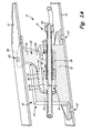
- FIG. 1A shows a perspective view of a section of a mount assembly disposed in an installed position between a first part and a second part.
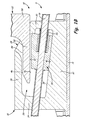
- FIG. 1B shows an enlarged sectional view of the mount assembly of FIG. 1A in a retracted uninstalled position.
- FIGS. 1A and 1B show a section of a mount assembly 10 disposed in an installed position in a cavity 11 between a first part 12 and a second part 14.
- Mount assembly 10 includes an actuation member 16, a main body 18, a block 20, a bayonet 22, and a bias element 24.
- Main body 18 includes a cavity 26, an entrance 28, a first wall 30, a second wall 32, a third wall 34, and a fourth wall 36.
- Second wall 32 includes a ramp 38.
- Fourth wall 36 includes an interior surface 46.
- Block 20 includes a first interface surface 40, a second interface surface 42, and a receptacle 44.
- Bayonet 22 includes a main body 48, a heel 50, and a foot 52. Foot 52 includes a first interface surface 54, a second interface surface 56, and a mounting plate 58.
- First part 12 includes a hole 60.
- Second part 14 includes holes 62.
- mounts are secured using fasteners.
- mounts used to support the panels and liners can be difficult to access from external to the liners and panels for assembly and disassembly purposes. In such situations it may not be feasible to use fasteners and other mounting methods such as utilizing interconnecting parts with built-in clearances are employed.
- fasteners and other mounting methods such as utilizing interconnecting parts with built-in clearances are employed.
- this approach does not eliminate the clearances between the interconnecting parts, excessive wear of the mount can occur especially in a high vibration environment.
- the mount assembly 10 disclosed herein allows clearances between the components of mount assembly 10 to be reduced or eliminated even in the instance where mount assembly 10 is not readily accessible. This reduces the likelihood of wear.
- mount assembly 10 can be actuated remotely to create or reduce clearances to accomplish assembly or begin disassembly of mount 10 and liner/panel.
- Mount assembly 10 can be actuated remotely by extending actuation member 16 from mount 10 to an accessible location such as a location external to the liner/panel. Once clearances between components of mount 10 are accomplished by actuation, disassembly of mount assembly 10 and panels/liners can be accomplished by moving one panel relative to another.
- mount assembly 10 is disposed in cavity 11 between first part 12 and second part 14.
- first part 12 and second part 14 are spaced apart from one another and can comprise panels or liners that are supported by mount assembly 10.
- mount assembly 10 can be attached to portions of a single part rather than two or more parts.
- mount assembly 10 is not readily accessible within cavity 11 and indeed is actuateable only remotely via actuation member 16.
- Actuation member 16 extends through and is movable relative to main body 18. As illustrated in the installed position in FIG. 1A , main body 18 and bayonet 22 abut one another in firm engagement and bayonet 22 and block 20 abut one another in firm engagement. Bayonet 22 is connected to and extends from first part 12 into main body 18.
- Block 20 is movably disposed within main body 18 and is affixed to actuation member 16.
- Block 20 can be positioned to abut a lower portion of bayonet 22 by actuation member 16 and by bias element 24, which is also disposed within main body 18 about actuation member 16 in the embodiment shown.
- bias element 24 comprises a compression spring that operates to force block 20 into engagement with bayonet 22. Bias element 24 applies a load to keep block 20 in engagement with bayonet 22 when mount assembly 10 is in the installed position of FIG. 1A . As will be discussed subsequently, the load of bias element 24 is overcome by actuation member 16 to move block 20 to the uninstalled position of FIG. 1B .
- bias element 24 can additionally or alternatively include a jack screw 64 or other means known in the art for applying a load that keeps block 20 engaged with bayonet 22.
- main body 18 is affixed to second part 14, and is thus stationary relative to first part 12, bayonet 22, and actuation member 16.
- first part 12 and bayonet 22 are moved relative to main body 18 and second part 14 to provide access to cavity 11 (in the instance, for example, of a repair or installation) or to insert bayonet 22 into main body 18 to begin accomplishing the mounting of parts 12 and 14.
- bayonet 22 is inserted as shown in FIG. 1B , bayonet 22 is inserted further into cavity 26, and block 20 is advanced up ramp 38 within cavity 26 to bring main body 18, bayonet 22 and block 20 into firm abutting engagement with one another in the installed position of FIG. 1A .
- block 20 moves up ramp 38 to capture and hold bayonet 22 between block 20 and an inner wall (interior surface 46) of cavity 26.
- movement of block 20 up ramp 38 can be accomplished by actuation member 16.
- movement of block 20 up ramp 38 can be accomplished by bias element 24.
- movement of block up ramp 38 can be accomplished by both bias element 24 and actuation member 16.
- second part 14 and main body 18 can be moved relative to first part 12 and bayonet 22 to provide access to cavity 11 and to insert bayonet 22 into main body 18 to achieve the installed position.
- main body 18 has an internal cavity 26 with entrance 28 disposed to interface with and receive bayonet 22.
- cavity 26 is surrounded and formed by first wall 30, second wall 32, third wall 34, and fourth wall 36.
- Cavity 26 receives bayonet 22 via entrance 28, which is disposed between first wall 30 and fourth wall 36.
- First wall 30 is designed with a clearance from bayonet 22.
- fourth wall 36 initially has a clearance from bayonet 22. Together these clearances allow bayonet 22 to extend through entrance 28 into cavity 26 without interference.
- First wall 30 is disposed adjacent to bayonet 22 and extends away thereform. First wall 30 is adapted to receive actuation member 16, which extends therethrough into cavity 26. In the embodiment shown, first wall 30 is also contacted by bias element 24, a first end of a compression spring. First wall 30 transitions to second wall 32. Second wall 32 interfaces with second part 14 and is provided with ramp 38. Ramp 38 reduces the size of cavity 26 traveling distally away from bayonet 22 toward third wall 34.
- First interface surface 40 of block 20 interfaces and is slidably disposed on ramp 38.
- Block 20 has a wedge shape and is movable along ramp 38 from the installed position of FIG. 1A , to the uninstalled retracted position of FIG. 1B .
- Second interface surface 42 of block 20 interfaces with bayonet 22 and extends generally parallel thereto.
- Receptacle 44 is disposed between first interface surface 40 and second interface surface 42 and is adapted to receive actuation member 16 and bias element 24.
- ramp 38 (and thus first interface surface 40 of block 20) is sloped by an angle of about 6° relative to second interface surface 42 of block 20. In other embodiments, ramp 38 can be sloped relative to second interface surface 42 by a varying angular amount. The angle of slope ramp 38 will depend on various factors including the materials selected for main body 18 and block 20, desired tolerances, desired distance of travel of block 20, and the amount of load applied to block 20 by bias element 24.
- fourth wall 36 extends from third wall 34 toward bayonet 22 and entrance 28. Fourth wall 36 is disposed at a distance from first part 12. Interior surface 46 of fourth wall 36 extends along cavity 26 to interface with bayonet 22. When mount assembly 10 is in the uninstalled position shown in FIG. 1B , fourth wall 36 has a clearance from bayonet 22. When mount assembly 10 is in the installed position shown in FIG. 1A , fourth wall 36 is firmly abutted by and engaged with bayonet 22.
- Main body 48 of bayonet 22 is adapted to interface with an underside of first part 12 and be affixed thereto.
- the means for affixing main body 48 to first part 12 can vary from embodiment to embodiment and can include any means know in the art such as fasteners and high temperature adhesives.
- Main body 48 extends away from first part 12 to heel 50.
- heel 50 is disposed with clearance from first wall 30.
- Heel 50 transitions distally to foot 52.
- Foot 52 is adapted with a thickness to extend into cavity 26 with clearance from block 20 and fourth wall 36 when mount 10 is in the uninstalled position shown in FIG. 1B .
- first interface surface 54 of foot 52 has a clearance from interior surface 46 of fourth wall 36 in the uninstalled position of FIG. 1B .
- first part 12 interfaces with mounting plate 58 of bayonet 22.
- First part 12 and mounting plate 58 form hole 60.
- Hole 60 extends through first part 12 and into mounting plate 58 of bayonet 22.
- Hole 60 is adapted to receive a fastener (not shown) therein to affix bayonet 22 to first part 12.
- holes 62 extend through second part 14 and portions of main body 18. Holes 62 are adapted to receive various types of fasteners to affix main body 18 to second part 12.
- main body 18 is affixed to second part 14, and is thus stationary relative to first part 12, bayonet 22, and actuation member 16.
- First part 12 and bayonet 22 are moved relative to main body 18 and second part 14 to provide access to cavity 11 (in the instance, for example, of an installation or repair) or to insert bayonet 22 into main body 18 to begin to accomplish mounting of parts 12 and 14.
- bayonet 22 is inserted as shown in FIG. 1B , bayonet 22 is inserted further into cavity 26, and block 20 is actuated by actuation member 16 (and/or bias element 24) to bring main body 18, bayonet 22 and block 20 into firm abutting engagement with one another in the installed position of FIG. 1A .
- Bias element 24 applies a load to keep block 20 in engagement with bayonet 22 when mount 10 is in the installed position of FIG. 1A .
- the load of bias element 24 is overcome by actuation member 16 to move block 20 down ramp 38 to the uninstalled position of FIG. 1B .
- Bayonet 22 (along with first part 12) can then be moved to the position shown in FIG.
- bayonet 22 and first part 12 are moved away from main body 18 until bayonet 22 clears and is removed from main body 18. Once bayonet 22 is retracted, bayonet 22 and first part 12 can be removed allowing access to cavity 11.
- Mount assembly 10 as described allows clearances between the components of mount assembly 10 such as bayonet 22, main body 18, and block 20 to be reduced or eliminated even in the instance where mount assembly 10 is not readily accessible and must be remotely actuated. By reducing or eliminating clearances, reduced wear results to the components of mount assembly 10. Additionally, mount assembly 10 allows cavity 11, which might otherwise be difficult to access conventionally, to become more readily accessible.
Landscapes
- Engineering & Computer Science (AREA)
- Mechanical Engineering (AREA)
- General Engineering & Computer Science (AREA)
- Chemical & Material Sciences (AREA)
- Combustion & Propulsion (AREA)
- Connection Of Plates (AREA)
- Component Parts Of Construction Machinery (AREA)
- Roof Covering Using Slabs Or Stiff Sheets (AREA)
- Hooks, Suction Cups, And Attachment By Adhesive Means (AREA)
Abstract
Description
- The invention relates to an assembly and a method, and more particularly, to a mounting method and a mount assembly that can be used to support a part such as a liner or panel where access to the mount assembly is not readily accessible.
- Typically, mounting devices for parts such as liners and panels can be accessed at an underside location or along a perimeter of the part. Because the mounting device is accessible, a fastener or similar conventional linkage can be used to affix the mounting device to the part. In instances where the mounting device is not readily accessible, clearances must be built into the pieces of the mounting device to facilitate installation. These clearances are not reduced or eliminated after mounting is accomplished resulting in excessive wear to the pieces of the mounting device.
- A mount assembly includes a main body, a bayonet, and a block. The bayonet is movable relative the main body to insert a portion of the bayonet into an internal cavity of the main body. The block is disposed within the internal cavity and is movable relative to the main body from a first position to a second position. In the first position, the bayonet is captured and held between the block and an inner wall of the internal cavity. In the second position, the block allows the bayonet to be removed from the internal cavity.
- A mount assembly configured to support a first part includes a main body, a bayonet, and a block. The bayonet is connected to the first part and is movable relative the main body to insert a portion of the bayonet into an internal cavity of the main body. The block is disposed within the internal cavity and is movable relative to the main body from a first position where the bayonet abuts both the block and an inner wall of the internal cavity and a second position where the block is disposed at a distance from the bayonet. An actuation member extends into the internal cavity of the main body and is connected to the block. The actuation member extends outward from the main body into the cavity of the first part and is remotely actuatable at a distance from the mount assembly.
- A method of mounting a first part to a second part includes a bayonet, a main body, and a block. The bayonet is connected to the first part and disposed adjacent to the main body, which is connected to the second part. The bayonet is inserted into an internal cavity of the main body and the block is moved along a ramp within the internal cavity to abut the bayonet to capture and hold the bayonet between the block and an inner wall of the cavity.
-
FIG. 1A shows a perspective view of a section of a mount assembly disposed in an installed position between a first part and a second part. -
FIG. 1B shows an enlarged sectional view of the mount assembly ofFIG. 1A in a retracted uninstalled position. -
FIGS. 1A and1B show a section of amount assembly 10 disposed in an installed position in acavity 11 between afirst part 12 and asecond part 14.Mount assembly 10 includes anactuation member 16, amain body 18, ablock 20, abayonet 22, and abias element 24.Main body 18 includes acavity 26, anentrance 28, afirst wall 30, asecond wall 32, athird wall 34, and afourth wall 36.Second wall 32 includes aramp 38.Fourth wall 36 includes aninterior surface 46.Block 20 includes afirst interface surface 40, asecond interface surface 42, and areceptacle 44. Bayonet 22 includes amain body 48, aheel 50, and afoot 52. Foot 52 includes afirst interface surface 54, asecond interface surface 56, and amounting plate 58.First part 12 includes ahole 60.Second part 14 includesholes 62. - As previously discussed, many aircraft structures such as panels and liners must be mounted for structural support. Typically, mounts are secured using fasteners. Unfortunately in some situations, mounts used to support the panels and liners can be difficult to access from external to the liners and panels for assembly and disassembly purposes. In such situations it may not be feasible to use fasteners and other mounting methods such as utilizing interconnecting parts with built-in clearances are employed. However, as this approach does not eliminate the clearances between the interconnecting parts, excessive wear of the mount can occur especially in a high vibration environment. As will be discussed subsequently, the
mount assembly 10 disclosed herein allows clearances between the components ofmount assembly 10 to be reduced or eliminated even in the instance wheremount assembly 10 is not readily accessible. This reduces the likelihood of wear. Additionally,mount assembly 10 can be actuated remotely to create or reduce clearances to accomplish assembly or begin disassembly ofmount 10 and liner/panel.Mount assembly 10 can be actuated remotely by extendingactuation member 16 frommount 10 to an accessible location such as a location external to the liner/panel. Once clearances between components ofmount 10 are accomplished by actuation, disassembly ofmount assembly 10 and panels/liners can be accomplished by moving one panel relative to another. - As shown in
FIG. 1A ,mount assembly 10 is disposed incavity 11 betweenfirst part 12 andsecond part 14. In the embodiment shown,first part 12 andsecond part 14 are spaced apart from one another and can comprise panels or liners that are supported bymount assembly 10. In other embodiments,mount assembly 10 can be attached to portions of a single part rather than two or more parts. In the embodiment shown inFIG. 1A ,mount assembly 10 is not readily accessible withincavity 11 and indeed is actuateable only remotely viaactuation member 16. -
Actuation member 16 extends through and is movable relative tomain body 18. As illustrated in the installed position inFIG. 1A ,main body 18 and bayonet 22 abut one another in firm engagement andbayonet 22 and block 20 abut one another in firm engagement. Bayonet 22 is connected to and extends fromfirst part 12 intomain body 18. -
Block 20 is movably disposed withinmain body 18 and is affixed toactuation member 16.Block 20 can be positioned to abut a lower portion ofbayonet 22 byactuation member 16 and bybias element 24, which is also disposed withinmain body 18 aboutactuation member 16 in the embodiment shown. - In the embodiment shown,
bias element 24 comprises a compression spring that operates to forceblock 20 into engagement withbayonet 22.Bias element 24 applies a load to keepblock 20 in engagement withbayonet 22 whenmount assembly 10 is in the installed position ofFIG. 1A . As will be discussed subsequently, the load ofbias element 24 is overcome byactuation member 16 to moveblock 20 to the uninstalled position ofFIG. 1B . In other embodiments,bias element 24 can additionally or alternatively include ajack screw 64 or other means known in the art for applying a load that keepsblock 20 engaged withbayonet 22. - As illustrated in
FIG. 1A ,main body 18 is affixed tosecond part 14, and is thus stationary relative tofirst part 12,bayonet 22, andactuation member 16. As will be discussed subsequently, in the embodiment shown,first part 12 andbayonet 22 are moved relative tomain body 18 andsecond part 14 to provide access to cavity 11 (in the instance, for example, of a repair or installation) or to insertbayonet 22 intomain body 18 to begin accomplishing the mounting ofparts - After
bayonet 22 is inserted as shown inFIG. 1B ,bayonet 22 is inserted further intocavity 26, and block 20 is advanced upramp 38 withincavity 26 to bringmain body 18,bayonet 22 and block 20 into firm abutting engagement with one another in the installed position ofFIG. 1A . Thus, block 20 moves upramp 38 to capture and holdbayonet 22 betweenblock 20 and an inner wall (interior surface 46) ofcavity 26. In one embodiment, movement ofblock 20 upramp 38 can be accomplished byactuation member 16. In another embodiment, movement ofblock 20 upramp 38 can be accomplished bybias element 24. In yet a third embodiment, movement of block upramp 38 can be accomplished by bothbias element 24 andactuation member 16. In other embodiments,second part 14 andmain body 18 can be moved relative tofirst part 12 andbayonet 22 to provide access tocavity 11 and to insertbayonet 22 intomain body 18 to achieve the installed position. - As shown in
FIGS. 1A and1B ,main body 18 has aninternal cavity 26 withentrance 28 disposed to interface with and receivebayonet 22. In the embodiment shown,cavity 26 is surrounded and formed byfirst wall 30,second wall 32,third wall 34, andfourth wall 36.Cavity 26 receivesbayonet 22 viaentrance 28, which is disposed betweenfirst wall 30 andfourth wall 36.First wall 30 is designed with a clearance frombayonet 22. Similarly,fourth wall 36 initially has a clearance frombayonet 22. Together these clearances allowbayonet 22 to extend throughentrance 28 intocavity 26 without interference. -
First wall 30 is disposed adjacent to bayonet 22 and extends away thereform.First wall 30 is adapted to receiveactuation member 16, which extends therethrough intocavity 26. In the embodiment shown,first wall 30 is also contacted bybias element 24, a first end of a compression spring. First wall 30 transitions tosecond wall 32.Second wall 32 interfaces withsecond part 14 and is provided withramp 38.Ramp 38 reduces the size ofcavity 26 traveling distally away frombayonet 22 towardthird wall 34. -
First interface surface 40 ofblock 20 interfaces and is slidably disposed onramp 38.Block 20 has a wedge shape and is movable alongramp 38 from the installed position ofFIG. 1A , to the uninstalled retracted position ofFIG. 1B .Second interface surface 42 ofblock 20 interfaces withbayonet 22 and extends generally parallel thereto.Receptacle 44 is disposed betweenfirst interface surface 40 andsecond interface surface 42 and is adapted to receiveactuation member 16 andbias element 24. - In the embodiment shown in
FIGS. 1A and1B , ramp 38 (and thusfirst interface surface 40 of block 20) is sloped by an angle of about 6° relative tosecond interface surface 42 ofblock 20. In other embodiments, ramp 38 can be sloped relative tosecond interface surface 42 by a varying angular amount. The angle ofslope ramp 38 will depend on various factors including the materials selected formain body 18 andblock 20, desired tolerances, desired distance of travel ofblock 20, and the amount of load applied to block 20 bybias element 24. - In the embodiment shown,
fourth wall 36 extends fromthird wall 34 towardbayonet 22 andentrance 28.Fourth wall 36 is disposed at a distance fromfirst part 12.Interior surface 46 offourth wall 36 extends alongcavity 26 to interface withbayonet 22. Whenmount assembly 10 is in the uninstalled position shown inFIG. 1B ,fourth wall 36 has a clearance frombayonet 22. Whenmount assembly 10 is in the installed position shown inFIG. 1A ,fourth wall 36 is firmly abutted by and engaged withbayonet 22. -
Main body 48 ofbayonet 22 is adapted to interface with an underside offirst part 12 and be affixed thereto. The means for affixingmain body 48 tofirst part 12 can vary from embodiment to embodiment and can include any means know in the art such as fasteners and high temperature adhesives.Main body 48 extends away fromfirst part 12 toheel 50. As previously discussed,heel 50 is disposed with clearance fromfirst wall 30. Heel 50 transitions distally tofoot 52.Foot 52 is adapted with a thickness to extend intocavity 26 with clearance fromblock 20 andfourth wall 36 whenmount 10 is in the uninstalled position shown inFIG. 1B . Thus,first interface surface 54 offoot 52 has a clearance frominterior surface 46 offourth wall 36 in the uninstalled position ofFIG. 1B . In the installed position ofFIG. 1A ,interior surface 46 firmly abuts and is engaged byfirst interface surface 54. Similarly, in the installed position ofFIG. 1A withblock 20 moved upramp 38,second interface surface 56 abuts and is engaged bysecond interface surface 42 ofblock 20. In the un-installed position ofFIG. 1B , block 20 is actuated down ramp 38 (against the resistance of bias element 24) leaving a clearance betweensecond interface surface 42 andsecond interface surface 56. - In
FIG. 1A ,first part 12 interfaces with mountingplate 58 ofbayonet 22.First part 12 and mountingplate 58form hole 60.Hole 60 extends throughfirst part 12 and into mountingplate 58 ofbayonet 22.Hole 60 is adapted to receive a fastener (not shown) therein to affixbayonet 22 tofirst part 12. Similarly, holes 62 extend throughsecond part 14 and portions ofmain body 18.Holes 62 are adapted to receive various types of fasteners to affixmain body 18 tosecond part 12. - In the embodiment shown in
FIGS. 1A and1B ,main body 18 is affixed tosecond part 14, and is thus stationary relative tofirst part 12,bayonet 22, andactuation member 16.First part 12 andbayonet 22 are moved relative tomain body 18 andsecond part 14 to provide access to cavity 11 (in the instance, for example, of an installation or repair) or to insertbayonet 22 intomain body 18 to begin to accomplish mounting ofparts - After
bayonet 22 is inserted as shown inFIG. 1B ,bayonet 22 is inserted further intocavity 26, and block 20 is actuated by actuation member 16 (and/or bias element 24) to bringmain body 18,bayonet 22 and block 20 into firm abutting engagement with one another in the installed position ofFIG. 1A .Bias element 24 applies a load to keepblock 20 in engagement withbayonet 22 whenmount 10 is in the installed position ofFIG. 1A . To disassemblemount assembly 10, the load ofbias element 24 is overcome byactuation member 16 to moveblock 20 downramp 38 to the uninstalled position ofFIG. 1B . Bayonet 22 (along with first part 12) can then be moved to the position shown inFIG. 1B withbayonet 22 partially retracted fromcavity 26. To accesscavity 11,bayonet 22 andfirst part 12 are moved away frommain body 18 untilbayonet 22 clears and is removed frommain body 18. Oncebayonet 22 is retracted,bayonet 22 andfirst part 12 can be removed allowing access tocavity 11. -
Mount assembly 10 as described allows clearances between the components ofmount assembly 10 such asbayonet 22,main body 18, and block 20 to be reduced or eliminated even in the instance wheremount assembly 10 is not readily accessible and must be remotely actuated. By reducing or eliminating clearances, reduced wear results to the components ofmount assembly 10. Additionally, mountassembly 10 allowscavity 11, which might otherwise be difficult to access conventionally, to become more readily accessible. - While the invention has been described with reference to an exemplary embodiment, it will be understood by those skilled in the art that various changes may be made and equivalents may be substituted for elements thereof without departing from the scope of the invention, which is defined by the appended claims. In addition, many modifications may be made to adapt a particular situation or material to the teachings of the invention without departing from the essential scope thereof. Therefore, it is intended that the invention not be limited to the particular embodiment disclosed, but that the invention will include all embodiments falling within the scope of the appended claims.
Claims (15)
- A mount assembly (10) comprising:a main body (18) having an internal cavity (26);a bayonet (22) movable relative to the main body to insert a portion of the bayonet into the internal cavity; anda block (20) disposed within the internal cavity and movable relative to the main body between a first position and a second position, wherein in the first position the bayonet (22) is captured and held between the block (20) and an inner wall (46) of the internal cavity (26) and in the second position the block is retracted from contact with the bayonet to allow the bayonet to be removed from the internal cavity.
- The mount assembly of claim 1, wherein in the second position the block (20) is disposed at a clearance distance from the bayonet (22).
- The mount assembly of claim 2, wherein in the second position the entire bayonet (22) is retracted and disposed at a distance from the main body (18).
- The mount assembly of claim 1, 2 or 3, further comprising at least a first part (12) connected to the bayonet (22), wherein the first part forms at least a portion of a cavity (11) in which the mount assembly (10) is disposed;
and preferably further comprising a second part (12) connected to the main body (18). - The mount assembly of claim 1, 2, 3 or 4, further comprising a bias element (24) that exerts a load on the block (20) to urge the block to either the first position or the second position and/or hold the block in the first or the second position.
- The mount assembly of claim 5, wherein the bias element (24) includes at least one of a compression spring and a jack screw (64), and wherein the bias element is disposed in at least one of the internal cavity (26) and external to the main body (18).
- The mount assembly of claim 5 or 6, further comprising an actuation member (16) that extends into the internal cavity (26) and is connected to the block (20), wherein the actuation member is capable of overcoming the load on the block by the bias element (24) to move the block to the second position; and/or wherein the actuation member (16) is remotely actuatable at a distance from the mount assembly (10).
- The mount assembly of claim 7, wherein the actuation member (24) extends from the main body (18) into a cavity (11) of a first part (12) connected to the bayonet (22).
- The mount assembly of any preceding claim, wherein the main body (18) includes a ramp (38) disposed along the internal cavity (26), and wherein the block (20) is movable along the ramp between the first position to the second position.
- The assembly of any preceding claim, wherein the bayonet (22) is movable to retract the portion of bayonet from the internal cavity (26).
- A method of mounting a first part (12) to a second part (14), the method comprising:disposing a bayonet (22) connected to the first part adjacent to a main body (18) connected to the second part;inserting the bayonet into an internal cavity (26) of the main body; andmoving a block (20) along a ramp (38) within the internal cavity to abut the bayonet to capture and hold the bayonet between the block and an inner wall (46) of the cavity.
- The method of claim 11, further comprising providing a bias element (24) that exerts a load on the block (20) to urge the block to capture the bayonet (22).
- The method of claim 12, wherein the block (20) is moved along the ramp (38) with a load applied by the bias element (24) and an actuation member (16).
- The method of claim 12 or 13, further comprising providing an actuation member (16) that exerts a load on the block (20) to move the block along the ramp (38).
- The method of claim 11, 12, 13 or 14, wherein the block (20) is disposed at a distance from the bayonet (22) upon insertion of the bayonet into the internal cavity (26) of the main body (18).
Applications Claiming Priority (1)
| Application Number | Priority Date | Filing Date | Title |
|---|---|---|---|
| US13/285,348 US8967570B2 (en) | 2011-10-31 | 2011-10-31 | Blind retention mount |
Publications (3)
| Publication Number | Publication Date |
|---|---|
| EP2587001A2 true EP2587001A2 (en) | 2013-05-01 |
| EP2587001A3 EP2587001A3 (en) | 2018-01-03 |
| EP2587001B1 EP2587001B1 (en) | 2019-07-03 |
Family
ID=47278651
Family Applications (1)
| Application Number | Title | Priority Date | Filing Date |
|---|---|---|---|
| EP12190916.2A Active EP2587001B1 (en) | 2011-10-31 | 2012-10-31 | Blind retention mount |
Country Status (2)
| Country | Link |
|---|---|
| US (1) | US8967570B2 (en) |
| EP (1) | EP2587001B1 (en) |
Families Citing this family (1)
| Publication number | Priority date | Publication date | Assignee | Title |
|---|---|---|---|---|
| US12351082B1 (en) * | 2024-01-04 | 2025-07-08 | Textron Innovations Inc. | Track lock mechanism |
Family Cites Families (44)
| Publication number | Priority date | Publication date | Assignee | Title |
|---|---|---|---|---|
| US2790437A (en) * | 1955-10-12 | 1957-04-30 | Welch Allyn Inc | Surgical instrument |
| US3605069A (en) | 1969-05-26 | 1971-09-14 | Bunker Ramo | Rigid electrical connector |
| US4159744A (en) * | 1977-12-09 | 1979-07-03 | Monte Anthony J | Fire extinguishant mechanism |
| US4156554A (en) * | 1978-04-07 | 1979-05-29 | International Telephone And Telegraph Corporation | Coaxial cable assembly |
| FR2521520A1 (en) * | 1982-02-15 | 1983-08-19 | Daude Martine | MARGINAL FINS WITH VARIABLE ANGLES OF ATTACK |
| US5128830A (en) | 1990-07-02 | 1992-07-07 | Digital Equipment Corporation | Integrated installation assembly with self aligning connector |
| US5176339A (en) * | 1991-09-30 | 1993-01-05 | Lord Corporation | Resilient pivot type aircraft mounting |
| US5513630A (en) * | 1995-03-08 | 1996-05-07 | Century; Theodore J. | Powder dispenser |
| FR2755770B1 (en) | 1996-11-12 | 1999-01-22 | Sextant Avionique | HELMET WITH NIGHT VISION SYSTEM AND SUBSTITUTE OPTICS FOR DAY VISION |
| US6296088B1 (en) * | 1997-02-24 | 2001-10-02 | Lord Corporation | Magnetorheological fluid seismic damper |
| US6264113B1 (en) * | 1999-07-19 | 2001-07-24 | Steelcase Inc. | Fluid spraying system |
| EP1116624B1 (en) * | 1999-12-27 | 2004-07-14 | Ikeda Bussan Co., Ltd. | Vehicle seat slide device |
| US6551332B1 (en) * | 2000-03-31 | 2003-04-22 | Coalescent Surgical, Inc. | Multiple bias surgical fastener |
| US6668478B2 (en) * | 2000-12-01 | 2003-12-30 | Jason Bergstrom | Firearm pneumatic counter-recoil modulator & airgun thrust-adjustor |
| JP4363799B2 (en) * | 2001-06-08 | 2009-11-11 | 株式会社東芝 | Turbine assembly transport stand, turbine assembly method using the stand, and transport method |
| CA2365754A1 (en) * | 2001-12-14 | 2003-06-14 | S&C Electric Company | Rapid-release frangible fastener |
| US7462008B2 (en) * | 2002-05-02 | 2008-12-09 | Pilgrim Screw Corporation | Structural fasteners and components thereof |
| US6547181B1 (en) * | 2002-05-29 | 2003-04-15 | The Boeing Company | Ground effect wing having a variable sweep winglet |
| US6732984B2 (en) * | 2002-05-29 | 2004-05-11 | David Tsai | Support apparatus |
| JP4234675B2 (en) * | 2002-07-11 | 2009-03-04 | テクファーマ・ライセンシング・アクチェンゲゼルシャフト | Needleless injection device |
| US9486581B2 (en) * | 2002-09-11 | 2016-11-08 | Becton, Dickinson And Company | Injector device with force lock-out and injection rate limiting mechanisms |
| CN100404768C (en) * | 2003-09-26 | 2008-07-23 | Thk株式会社 | wall mount |
| US7111424B1 (en) * | 2003-12-02 | 2006-09-26 | Moody Joseph R | Fore grip with bipod |
| DE102005044610A1 (en) | 2004-09-28 | 2006-03-30 | Hirschmann Car Communication Gmbh | Antenna and method for mounting an antenna to a vehicle by means of clamping force, preferably generated by a rotating bayonet |
| US7441981B2 (en) * | 2005-04-15 | 2008-10-28 | Crain Enterprises, Inc. | Coupler for a mount system |
| EP1733849A1 (en) * | 2005-06-15 | 2006-12-20 | Caterpillar, Inc. | Tool assembly having a two part body |
| US20080029575A1 (en) * | 2006-08-02 | 2008-02-07 | Shelton Frederick E | Surgical cutting and fastening instrument with distally mounted pneumatically powered rotary drive member |
| EP1923084A1 (en) * | 2006-11-17 | 2008-05-21 | Sanofi-Aventis Deutschland GmbH | Dosing and drive mechanism for drug delivery device |
| US8136766B2 (en) * | 2008-02-01 | 2012-03-20 | Insitu, Inc. | Frangible fasteners for aircraft components and associated systems and methods |
| GB2459886A (en) * | 2008-05-09 | 2009-11-11 | Fusion Components Ltd | Shielded electrical connector having resiliently urging means making electrical connection between cable shield and connector |
| US8256750B2 (en) * | 2009-02-18 | 2012-09-04 | Honeywell International Inc. | Vibration isolation mounting assembly |
| US9242040B2 (en) * | 2009-04-23 | 2016-01-26 | Bayer Healthcare Llc | Syringe assemblies, methods of forming syringe assemblies and adapters for forming syringe assemblies |
| WO2010127146A1 (en) * | 2009-04-29 | 2010-11-04 | Abbott Biotechnology Ltd | Automatic injection device |
| EP2437816B1 (en) * | 2009-06-04 | 2013-04-24 | Novo Nordisk Health Care AG | Mixing device with piston coupling arrangement |
| US8231144B2 (en) * | 2009-06-23 | 2012-07-31 | Honeywell International, Inc. | Joint assemblies |
| AU2010206081B2 (en) * | 2009-08-07 | 2014-10-02 | John Guest International Limited | Improvements in or relating to connectors for cable carrying conduits |
| US8328113B2 (en) * | 2009-11-11 | 2012-12-11 | The Last Straw Llc | Snap-fit valve and straw assembly and method of using same |
| US8646357B2 (en) * | 2009-12-02 | 2014-02-11 | Ford Global Technologies, Llc | Vehicle braking assembly with gap management system |
| US8307499B2 (en) * | 2010-12-09 | 2012-11-13 | Fabian Ruffo | Hanger for window drape and slide assembly including hanger |
| US8667659B2 (en) * | 2011-01-19 | 2014-03-11 | Mettler-Toledo Ag | System and method for coupling an extendable element to an actuator |
| US9217614B2 (en) * | 2011-02-11 | 2015-12-22 | Jorge Pizano | Firearm having an articulated bolt train with transversally displacing firing mechanism, delay blowback breech opening, and recoil damper |
| CA2776761C (en) * | 2011-05-12 | 2019-07-16 | Cantega Technologies Inc. | Tool and method for handling a part |
| US20130068199A1 (en) * | 2011-09-21 | 2013-03-21 | Chrysler Group LLC. | High pressure solenoid |
| US9155863B2 (en) * | 2011-10-06 | 2015-10-13 | Becton, Dickinson And Company | Multiple use stretching and non-penetrating blood control valves |
-
2011
- 2011-10-31 US US13/285,348 patent/US8967570B2/en not_active Expired - Fee Related
-
2012
- 2012-10-31 EP EP12190916.2A patent/EP2587001B1/en active Active
Non-Patent Citations (1)
| Title |
|---|
| None |
Also Published As
| Publication number | Publication date |
|---|---|
| US20130105652A1 (en) | 2013-05-02 |
| EP2587001B1 (en) | 2019-07-03 |
| EP2587001A3 (en) | 2018-01-03 |
| US8967570B2 (en) | 2015-03-03 |
Similar Documents
| Publication | Publication Date | Title |
|---|---|---|
| KR101074444B1 (en) | A connecting assembly for fastening an add-on element on a carrier element | |
| EP2716500B1 (en) | Roofrail with fastening system | |
| JP6154896B2 (en) | Holder for irregular section rail | |
| EP2436600B1 (en) | Seat track and monument attach fastener | |
| US9359012B2 (en) | Tolerance compensator for a vehicle frame | |
| RU2549229C1 (en) | Structural group with at least two structural elements fixed with each other | |
| US20100178105A1 (en) | Device for a pavement manhole with a support frame for closing a panel hinged on the frame using permanent articulation means | |
| US9051956B2 (en) | Panel fastener with hold-down ring | |
| US8857879B2 (en) | Fastening of a longitudinal beam lining on a longitudinal beam of a motor vechicle | |
| CN105555660B (en) | Self-aligning assembly and systems and methods including self-aligning assembly | |
| CN107615207B (en) | Fastenerless hinges that enable low-cost designs in thin form factors | |
| CN110878660A (en) | Tolerance Compensation Hinge Attachment | |
| US8967570B2 (en) | Blind retention mount | |
| CN104154100A (en) | Slide rail for tensioning and guiding an endless drive member and method for manufacturing said slide rail | |
| CN104864249A (en) | Advertising board installation device with U-shaped infrared sensor | |
| CN103612061A (en) | Fixing fixture for welding middle shaft of bottom shell of automobile seat adjustor | |
| WO2009015809A3 (en) | Fastening system for quick-releasably fastening interior components in the cabin of an aircraft | |
| US20080080948A1 (en) | Rail to truck panel attachment mount | |
| US20170120318A1 (en) | Swivel jig tool for forming burring hole in door inner panel of vehicle and method of operating the same | |
| JP4355199B2 (en) | Active food equipment | |
| CN104936840B (en) | Keep component | |
| US11577586B2 (en) | Collapsible side door latch module | |
| RU2675754C2 (en) | Motor vehicle footpad assembly | |
| KR101654477B1 (en) | top mount insulator of front damper assembly anti-rotating jig for automobile | |
| JP2014104813A (en) | Fitting position adjustment jig of slide door |
Legal Events
| Date | Code | Title | Description |
|---|---|---|---|
| PUAI | Public reference made under article 153(3) epc to a published international application that has entered the european phase |
Free format text: ORIGINAL CODE: 0009012 |
|
| AK | Designated contracting states |
Kind code of ref document: A2 Designated state(s): AL AT BE BG CH CY CZ DE DK EE ES FI FR GB GR HR HU IE IS IT LI LT LU LV MC MK MT NL NO PL PT RO RS SE SI SK SM TR |
|
| AX | Request for extension of the european patent |
Extension state: BA ME |
|
| RAP1 | Party data changed (applicant data changed or rights of an application transferred) |
Owner name: UNITED TECHNOLOGIES CORPORATION |
|
| PUAL | Search report despatched |
Free format text: ORIGINAL CODE: 0009013 |
|
| AK | Designated contracting states |
Kind code of ref document: A3 Designated state(s): AL AT BE BG CH CY CZ DE DK EE ES FI FR GB GR HR HU IE IS IT LI LT LU LV MC MK MT NL NO PL PT RO RS SE SI SK SM TR |
|
| AX | Request for extension of the european patent |
Extension state: BA ME |
|
| RIC1 | Information provided on ipc code assigned before grant |
Ipc: F01D 25/28 20060101ALI20171130BHEP Ipc: F01D 25/24 20060101AFI20171130BHEP Ipc: F02K 1/80 20060101ALI20171130BHEP |
|
| STAA | Information on the status of an ep patent application or granted ep patent |
Free format text: STATUS: REQUEST FOR EXAMINATION WAS MADE |
|
| 17P | Request for examination filed |
Effective date: 20180703 |
|
| RBV | Designated contracting states (corrected) |
Designated state(s): AL AT BE BG CH CY CZ DE DK EE ES FI FR GB GR HR HU IE IS IT LI LT LU LV MC MK MT NL NO PL PT RO RS SE SI SK SM TR |
|
| RIC1 | Information provided on ipc code assigned before grant |
Ipc: F02K 1/80 20060101ALI20180928BHEP Ipc: F01D 25/24 20060101AFI20180928BHEP Ipc: F01D 25/28 20060101ALI20180928BHEP |
|
| GRAP | Despatch of communication of intention to grant a patent |
Free format text: ORIGINAL CODE: EPIDOSNIGR1 |
|
| STAA | Information on the status of an ep patent application or granted ep patent |
Free format text: STATUS: GRANT OF PATENT IS INTENDED |
|
| INTG | Intention to grant announced |
Effective date: 20190114 |
|
| GRAS | Grant fee paid |
Free format text: ORIGINAL CODE: EPIDOSNIGR3 |
|
| GRAA | (expected) grant |
Free format text: ORIGINAL CODE: 0009210 |
|
| STAA | Information on the status of an ep patent application or granted ep patent |
Free format text: STATUS: THE PATENT HAS BEEN GRANTED |
|
| AK | Designated contracting states |
Kind code of ref document: B1 Designated state(s): AL AT BE BG CH CY CZ DE DK EE ES FI FR GB GR HR HU IE IS IT LI LT LU LV MC MK MT NL NO PL PT RO RS SE SI SK SM TR |
|
| REG | Reference to a national code |
Ref country code: GB Ref legal event code: FG4D |
|
| REG | Reference to a national code |
Ref country code: CH Ref legal event code: EP Ref country code: AT Ref legal event code: REF Ref document number: 1151250 Country of ref document: AT Kind code of ref document: T Effective date: 20190715 |
|
| REG | Reference to a national code |
Ref country code: IE Ref legal event code: FG4D |
|
| REG | Reference to a national code |
Ref country code: DE Ref legal event code: R096 Ref document number: 602012061620 Country of ref document: DE |
|
| REG | Reference to a national code |
Ref country code: NL Ref legal event code: MP Effective date: 20190703 |
|
| REG | Reference to a national code |
Ref country code: LT Ref legal event code: MG4D |
|
| REG | Reference to a national code |
Ref country code: AT Ref legal event code: MK05 Ref document number: 1151250 Country of ref document: AT Kind code of ref document: T Effective date: 20190703 |
|
| PG25 | Lapsed in a contracting state [announced via postgrant information from national office to epo] |
Ref country code: AT Free format text: LAPSE BECAUSE OF FAILURE TO SUBMIT A TRANSLATION OF THE DESCRIPTION OR TO PAY THE FEE WITHIN THE PRESCRIBED TIME-LIMIT Effective date: 20190703 Ref country code: HR Free format text: LAPSE BECAUSE OF FAILURE TO SUBMIT A TRANSLATION OF THE DESCRIPTION OR TO PAY THE FEE WITHIN THE PRESCRIBED TIME-LIMIT Effective date: 20190703 Ref country code: SE Free format text: LAPSE BECAUSE OF FAILURE TO SUBMIT A TRANSLATION OF THE DESCRIPTION OR TO PAY THE FEE WITHIN THE PRESCRIBED TIME-LIMIT Effective date: 20190703 Ref country code: FI Free format text: LAPSE BECAUSE OF FAILURE TO SUBMIT A TRANSLATION OF THE DESCRIPTION OR TO PAY THE FEE WITHIN THE PRESCRIBED TIME-LIMIT Effective date: 20190703 Ref country code: NO Free format text: LAPSE BECAUSE OF FAILURE TO SUBMIT A TRANSLATION OF THE DESCRIPTION OR TO PAY THE FEE WITHIN THE PRESCRIBED TIME-LIMIT Effective date: 20191003 Ref country code: NL Free format text: LAPSE BECAUSE OF FAILURE TO SUBMIT A TRANSLATION OF THE DESCRIPTION OR TO PAY THE FEE WITHIN THE PRESCRIBED TIME-LIMIT Effective date: 20190703 Ref country code: BG Free format text: LAPSE BECAUSE OF FAILURE TO SUBMIT A TRANSLATION OF THE DESCRIPTION OR TO PAY THE FEE WITHIN THE PRESCRIBED TIME-LIMIT Effective date: 20191003 Ref country code: LT Free format text: LAPSE BECAUSE OF FAILURE TO SUBMIT A TRANSLATION OF THE DESCRIPTION OR TO PAY THE FEE WITHIN THE PRESCRIBED TIME-LIMIT Effective date: 20190703 Ref country code: PT Free format text: LAPSE BECAUSE OF FAILURE TO SUBMIT A TRANSLATION OF THE DESCRIPTION OR TO PAY THE FEE WITHIN THE PRESCRIBED TIME-LIMIT Effective date: 20191104 Ref country code: CZ Free format text: LAPSE BECAUSE OF FAILURE TO SUBMIT A TRANSLATION OF THE DESCRIPTION OR TO PAY THE FEE WITHIN THE PRESCRIBED TIME-LIMIT Effective date: 20190703 |
|
| PG25 | Lapsed in a contracting state [announced via postgrant information from national office to epo] |
Ref country code: RS Free format text: LAPSE BECAUSE OF FAILURE TO SUBMIT A TRANSLATION OF THE DESCRIPTION OR TO PAY THE FEE WITHIN THE PRESCRIBED TIME-LIMIT Effective date: 20190703 Ref country code: LV Free format text: LAPSE BECAUSE OF FAILURE TO SUBMIT A TRANSLATION OF THE DESCRIPTION OR TO PAY THE FEE WITHIN THE PRESCRIBED TIME-LIMIT Effective date: 20190703 Ref country code: AL Free format text: LAPSE BECAUSE OF FAILURE TO SUBMIT A TRANSLATION OF THE DESCRIPTION OR TO PAY THE FEE WITHIN THE PRESCRIBED TIME-LIMIT Effective date: 20190703 Ref country code: ES Free format text: LAPSE BECAUSE OF FAILURE TO SUBMIT A TRANSLATION OF THE DESCRIPTION OR TO PAY THE FEE WITHIN THE PRESCRIBED TIME-LIMIT Effective date: 20190703 Ref country code: GR Free format text: LAPSE BECAUSE OF FAILURE TO SUBMIT A TRANSLATION OF THE DESCRIPTION OR TO PAY THE FEE WITHIN THE PRESCRIBED TIME-LIMIT Effective date: 20191004 Ref country code: IS Free format text: LAPSE BECAUSE OF FAILURE TO SUBMIT A TRANSLATION OF THE DESCRIPTION OR TO PAY THE FEE WITHIN THE PRESCRIBED TIME-LIMIT Effective date: 20191103 |
|
| PG25 | Lapsed in a contracting state [announced via postgrant information from national office to epo] |
Ref country code: TR Free format text: LAPSE BECAUSE OF FAILURE TO SUBMIT A TRANSLATION OF THE DESCRIPTION OR TO PAY THE FEE WITHIN THE PRESCRIBED TIME-LIMIT Effective date: 20190703 |
|
| PG25 | Lapsed in a contracting state [announced via postgrant information from national office to epo] |
Ref country code: DK Free format text: LAPSE BECAUSE OF FAILURE TO SUBMIT A TRANSLATION OF THE DESCRIPTION OR TO PAY THE FEE WITHIN THE PRESCRIBED TIME-LIMIT Effective date: 20190703 Ref country code: PL Free format text: LAPSE BECAUSE OF FAILURE TO SUBMIT A TRANSLATION OF THE DESCRIPTION OR TO PAY THE FEE WITHIN THE PRESCRIBED TIME-LIMIT Effective date: 20190703 Ref country code: RO Free format text: LAPSE BECAUSE OF FAILURE TO SUBMIT A TRANSLATION OF THE DESCRIPTION OR TO PAY THE FEE WITHIN THE PRESCRIBED TIME-LIMIT Effective date: 20190703 Ref country code: EE Free format text: LAPSE BECAUSE OF FAILURE TO SUBMIT A TRANSLATION OF THE DESCRIPTION OR TO PAY THE FEE WITHIN THE PRESCRIBED TIME-LIMIT Effective date: 20190703 Ref country code: IT Free format text: LAPSE BECAUSE OF FAILURE TO SUBMIT A TRANSLATION OF THE DESCRIPTION OR TO PAY THE FEE WITHIN THE PRESCRIBED TIME-LIMIT Effective date: 20190703 |
|
| PG25 | Lapsed in a contracting state [announced via postgrant information from national office to epo] |
Ref country code: SM Free format text: LAPSE BECAUSE OF FAILURE TO SUBMIT A TRANSLATION OF THE DESCRIPTION OR TO PAY THE FEE WITHIN THE PRESCRIBED TIME-LIMIT Effective date: 20190703 Ref country code: IS Free format text: LAPSE BECAUSE OF FAILURE TO SUBMIT A TRANSLATION OF THE DESCRIPTION OR TO PAY THE FEE WITHIN THE PRESCRIBED TIME-LIMIT Effective date: 20200224 Ref country code: SK Free format text: LAPSE BECAUSE OF FAILURE TO SUBMIT A TRANSLATION OF THE DESCRIPTION OR TO PAY THE FEE WITHIN THE PRESCRIBED TIME-LIMIT Effective date: 20190703 Ref country code: MC Free format text: LAPSE BECAUSE OF FAILURE TO SUBMIT A TRANSLATION OF THE DESCRIPTION OR TO PAY THE FEE WITHIN THE PRESCRIBED TIME-LIMIT Effective date: 20190703 |
|
| REG | Reference to a national code |
Ref country code: CH Ref legal event code: PL |
|
| REG | Reference to a national code |
Ref country code: DE Ref legal event code: R097 Ref document number: 602012061620 Country of ref document: DE |
|
| PLBE | No opposition filed within time limit |
Free format text: ORIGINAL CODE: 0009261 |
|
| STAA | Information on the status of an ep patent application or granted ep patent |
Free format text: STATUS: NO OPPOSITION FILED WITHIN TIME LIMIT |
|
| PG2D | Information on lapse in contracting state deleted |
Ref country code: IS |
|
| PG25 | Lapsed in a contracting state [announced via postgrant information from national office to epo] |
Ref country code: LU Free format text: LAPSE BECAUSE OF NON-PAYMENT OF DUE FEES Effective date: 20191031 Ref country code: CH Free format text: LAPSE BECAUSE OF NON-PAYMENT OF DUE FEES Effective date: 20191031 Ref country code: LI Free format text: LAPSE BECAUSE OF NON-PAYMENT OF DUE FEES Effective date: 20191031 |
|
| 26N | No opposition filed |
Effective date: 20200603 |
|
| REG | Reference to a national code |
Ref country code: BE Ref legal event code: MM Effective date: 20191031 |
|
| PG25 | Lapsed in a contracting state [announced via postgrant information from national office to epo] |
Ref country code: BE Free format text: LAPSE BECAUSE OF NON-PAYMENT OF DUE FEES Effective date: 20191031 Ref country code: SI Free format text: LAPSE BECAUSE OF FAILURE TO SUBMIT A TRANSLATION OF THE DESCRIPTION OR TO PAY THE FEE WITHIN THE PRESCRIBED TIME-LIMIT Effective date: 20190703 |
|
| PG25 | Lapsed in a contracting state [announced via postgrant information from national office to epo] |
Ref country code: IE Free format text: LAPSE BECAUSE OF NON-PAYMENT OF DUE FEES Effective date: 20191031 |
|
| PG25 | Lapsed in a contracting state [announced via postgrant information from national office to epo] |
Ref country code: CY Free format text: LAPSE BECAUSE OF FAILURE TO SUBMIT A TRANSLATION OF THE DESCRIPTION OR TO PAY THE FEE WITHIN THE PRESCRIBED TIME-LIMIT Effective date: 20190703 |
|
| PG25 | Lapsed in a contracting state [announced via postgrant information from national office to epo] |
Ref country code: HU Free format text: LAPSE BECAUSE OF FAILURE TO SUBMIT A TRANSLATION OF THE DESCRIPTION OR TO PAY THE FEE WITHIN THE PRESCRIBED TIME-LIMIT; INVALID AB INITIO Effective date: 20121031 Ref country code: MT Free format text: LAPSE BECAUSE OF FAILURE TO SUBMIT A TRANSLATION OF THE DESCRIPTION OR TO PAY THE FEE WITHIN THE PRESCRIBED TIME-LIMIT Effective date: 20190703 |
|
| PG25 | Lapsed in a contracting state [announced via postgrant information from national office to epo] |
Ref country code: MK Free format text: LAPSE BECAUSE OF FAILURE TO SUBMIT A TRANSLATION OF THE DESCRIPTION OR TO PAY THE FEE WITHIN THE PRESCRIBED TIME-LIMIT Effective date: 20190703 |
|
| REG | Reference to a national code |
Ref country code: DE Ref legal event code: R081 Ref document number: 602012061620 Country of ref document: DE Owner name: RAYTHEON TECHNOLOGIES CORPORATION (N.D.GES.D.S, US Free format text: FORMER OWNER: UNITED TECHNOLOGIES CORPORATION, FARMINGTON, CONN., US |
|
| P01 | Opt-out of the competence of the unified patent court (upc) registered |
Effective date: 20230520 |
|
| PGFP | Annual fee paid to national office [announced via postgrant information from national office to epo] |
Ref country code: GB Payment date: 20240919 Year of fee payment: 13 |
|
| PGFP | Annual fee paid to national office [announced via postgrant information from national office to epo] |
Ref country code: FR Payment date: 20240919 Year of fee payment: 13 |
|
| PGFP | Annual fee paid to national office [announced via postgrant information from national office to epo] |
Ref country code: DE Payment date: 20240919 Year of fee payment: 13 |