EP2586706A1 - A propulsive system - Google Patents
A propulsive system Download PDFInfo
- Publication number
- EP2586706A1 EP2586706A1 EP12187090.1A EP12187090A EP2586706A1 EP 2586706 A1 EP2586706 A1 EP 2586706A1 EP 12187090 A EP12187090 A EP 12187090A EP 2586706 A1 EP2586706 A1 EP 2586706A1
- Authority
- EP
- European Patent Office
- Prior art keywords
- fan
- propulsive
- aircraft
- unit
- duct
- Prior art date
- Legal status (The legal status is an assumption and is not a legal conclusion. Google has not performed a legal analysis and makes no representation as to the accuracy of the status listed.)
- Granted
Links
Images


Classifications
-
- B—PERFORMING OPERATIONS; TRANSPORTING
- B64—AIRCRAFT; AVIATION; COSMONAUTICS
- B64D—EQUIPMENT FOR FITTING IN OR TO AIRCRAFT; FLIGHT SUITS; PARACHUTES; ARRANGEMENT OR MOUNTING OF POWER PLANTS OR PROPULSION TRANSMISSIONS IN AIRCRAFT
- B64D27/00—Arrangement or mounting of power plants in aircraft; Aircraft characterised by the type or position of power plants
- B64D27/02—Aircraft characterised by the type or position of power plants
-
- B—PERFORMING OPERATIONS; TRANSPORTING
- B64—AIRCRAFT; AVIATION; COSMONAUTICS
- B64C—AEROPLANES; HELICOPTERS
- B64C2230/00—Boundary layer controls
- B64C2230/28—Boundary layer controls at propeller or rotor blades
-
- Y—GENERAL TAGGING OF NEW TECHNOLOGICAL DEVELOPMENTS; GENERAL TAGGING OF CROSS-SECTIONAL TECHNOLOGIES SPANNING OVER SEVERAL SECTIONS OF THE IPC; TECHNICAL SUBJECTS COVERED BY FORMER USPC CROSS-REFERENCE ART COLLECTIONS [XRACs] AND DIGESTS
- Y02—TECHNOLOGIES OR APPLICATIONS FOR MITIGATION OR ADAPTATION AGAINST CLIMATE CHANGE
- Y02T—CLIMATE CHANGE MITIGATION TECHNOLOGIES RELATED TO TRANSPORTATION
- Y02T50/00—Aeronautics or air transport
- Y02T50/10—Drag reduction
Definitions
- This invention relates to a propulsive system for an aircraft.
- the invention relates to a propulsive system for ingestion of boundary layer air.
- One known option for distributed propulsion is to provide numerous propulsive units which are located so as to capture and accelerate slow speed boundary layer air which has formed against the surface of the aircraft. This can lead to a significant reduction in overall fuel burn with the maximum benefit of boundary layer ingestion being achieved when the low speed flow is not mixed with the freestream flow, but is accelerated to homogeneous conditions by the propulsion system.
- the present invention seeks to provide an improved propulsive device for ingesting boundary layer air.
- the present invention provides an aircraft comprising: a first propulsive unit having a first fan with an axis of rotation; and a second propulsive unit located so as to receive an airflow from the first propulsive unit, the second propulsive unit having a second fan with an axis of rotation, wherein the rotational axis of the first fan is proximate to the surface of the aircraft relative to the rotational axis of the second fan such that the first fan ingests boundary layer air when in use.
- Providing an arrangement according to the first aspect allows the propulsive units to ingest both boundary layer air and free stream air with a greater efficiency and also helps reduce vibration and mechanical wear in the propulsive system.
- the first and second propulsive units may be any one or more of: adjacent to one another; in a linear series; upstream and downstream and stacked one on top of the other; placed on a similar surface on the aircraft; and, separated by a dimension which is less than twice the diameter of the second fan.
- the second propulsive unit may be arranged so as to receive an airflow from an outlet of the first propulsive unit.
- the rotational axes may be in a common plane.
- the common plane may be vertical.
- first propulsion units for each second propulsive unit.
- the first propulsive units may be arranged across an inlet of the second propulsive unit.
- the diameter of the first fan may be smaller than that of the second fan.
- the first fan may have a diameter in the range of between 40cm and 62cm.
- the second fan may have a diameter in the range of between 200cm and 325cm.
- the ratio of the first fan diameter to the second fan diameter may be between approximately 0.12:1 and 0.3:1. It will be appreciated that these ranges may vary depending on the number installed and the aircraft design and the ratio may be up to 0.4:1.
- the first fan may be upstream of the second fan and accelerate boundary layer air for ingestion of the second fan.
- the second fan may be adjacent to a surface of the aircraft.
- the propulsive unit may further comprise a plurality of first propulsive units for each second propulsive unit.
- the outlet of the first propulsive unit may be ducted into the second propulsive unit downstream from the blades of the second fan.
- the axial separation between the outlet of the first and second fan may be a maximum of twice the second fan diameter.
- Figure 1 shows a propulsive system 10 for an aircraft 11 comprising a first propulsive unit 12 and a second propulsive unit 14.
- the first propulsive unit 12 includes a first fan unit 16 having a plurality of blades 18 mounted on a rotatable hub 20 having a rotational axis 22.
- the rotatable hub 20 is mounted to and driven by an electrical machine drive 24.
- the drive 24, hub 20 and blades 18 are supported within a duct 26 by a plurality of struts 28.
- the duct 26 is bounded by a duct wall 29 and has an inlet 30 for receiving air and an outlet 32 for exhausting air and providing a propulsive force to the aircraft 11.
- the first propulsive unit 12 is mounted on a surface 33 of an aircraft 11 such that the lower parts of the duct 26 wall provide a continuation of the aircraft surface 33 and the upper parts define a nacelle 34.
- the duct 26 is dimensioned to provide a close fit for rotational path of the fan blades 18 and may include abradable fan track liners and acoustic treatments as are known in the art but not shown here for the sake of clarity. It will also be appreciated that, although incorporating the duct 26 into the surface of the aircraft so as to provide a smooth gas washed surface is advantageous, it is not a limitation of the invention and the duct wall can be located on a support structure such as a pylon.
- the term propulsive does not imply that the first unit exhausts an airflow which directly propels the aircraft. Nevertheless, the air accelerated by the first fan unit does act to propel the aircraft when in use, even if it is after the air has been further accelerated by the second propulsive unit.
- Boundary layer air is air which forms close to the surface of an aircraft 11 and as such has a low flow velocity.
- Boundary layer air on a conventional tube and wing aircraft is typically thickest towards the rear portions of the fuselage and the rearward portions of the wings.
- boundary layer air it will be understood that the term relates to a layer of air on a surface in contact with a moving fluid and may be defined as the portion of the flow near to the surface with a speed that is below 99% of the speed of an equivalent inviscid flow at the same location and conditions. When the velocity of the flow is above 99% of the inviscid case (e.g. almost unchanged) the flow is considered to be outside the boundary layer. Thickness of the boundary layer increases proportionally to the length of the surface it is flowing onto, as it is slowing down due to friction effects.
- the second propulsive unit 14 is similar to the first propulsive unit 12 in that it includes a second fan unit 36 having a plurality of blades 38 mounted on a rotatable hub 40.
- the rotational hub 40 has rotational axis 42 and is mounted to and driven by an electrical machine drive 44.
- the blades 38, hub 40 and drive 44 are all supported within a duct 46 by a plurality of struts 48.
- the duct 46 is bounded by a duct wall 50 and has an inlet 52 for receiving air and an outlet 54 for exhausting air and providing a propulsive force to the aircraft 11.
- the lower parts of the second propulsive unit duct wall 50 provide a continuation of the aircraft surface 33 and the upper parts define a nacelle 58.
- the second propulsive unit duct 46 is dimensioned to provide a close fit for the rotational path of the fan blades 38 and may include abradable fan track liners and acoustic treatments as are known in the art but not shown here for the sake of clarity. It will also be appreciated that, although incorporating the duct 46 into the surface 33 of the aircraft 11 so as to provide a smooth gas washed surface is advantageous, it is not a limitation of the invention and the duct wall 50 can be located on a support structure such as a pylon.
- the first propulsive unit 12 is mounted upstream of the second propulsive unit 14 on the surface 33 of the aircraft 11 with the rotational axes 22, 42 of the two units running in parallel.
- the first propulsive unit 12 is smaller than the second propulsive unit 14 in that the diameter of the first fan unit 16 is smaller than the diameter of the second fan unit 36.
- the rotational axis 22 of the first fan unit 16 is proximate to the surface 33 of the aircraft 11 relative to the rotational axis 42 of the second fan unit.
- the inlet or nacelle of propulsive unit 12 is located closer to surface 33 of the aircraft 11 such that it is substantially within the boundary layer air when in use.
- the aircraft 11 moves through the air from right to left with reference to Figure 1 such that an airflow is created from left to right which is ingested by the propulsive units 12, 14.
- the first propulsive unit 12 ingests boundary layer air and accelerates it for ingestion by the second propulsive unit 14.
- the second propulsive unit 14 ingests air which has been accelerated by the first fan unit 16, and free flow air which passes over the first propulsive unit 12.
- the total pressure and velocity differential experienced across the span of the second fan units' 36 fan blades 38 is reduced and the air which is ingested is more circumferentially homogenous. This helps reduce mechanical wear and vibrations on the second fan unit 36 which would be experienced if the fan 36 were to ingest both free flow air and un-accelerated boundary layer air.
- Figure 2 shows an axial series of cross sections, A to H at evenly spaced intervals along the principal axis 242 of the propulsive system.
- sections of the first propulsive unit, A to F, and a second propulsive, F to H, unit which are arranged in a series flow relationship such that air exiting the first propulsive unit enters the second propulsive unit.
- the first propulsive unit includes a first fan unit having a plurality of blades 218 mounted on a rotatable hub 220 having a rotational axis 222.
- the rotatable hub 220 is mounted to and driven by an electrical machine drive 224.
- the drive 224, hub 220 and blades 218 are supported within a duct 226 by a plurality of struts 228.
- the duct 226 is bounded by a duct wall and has an inlet 230 for receiving air and an outlet 232 for exhausting air and providing a propulsive force to the aircraft.
- propulsive force it will be appreciated that this may not be a direct propulsive force as the outlet does not provide an airstream which directly exits the aircraft. Nevertheless, the air accelerated by the first fan unit does act to propel the aircraft when in use, even if it is after the air has been further accelerated by the second propulsive unit.
- the first propulsive unit is mounted on a surface 233 of an aircraft such that the lower parts of the duct 226 wall provide a continuation of the aircraft surface 233 and the side walls define a nacelle 234.
- the upper surface of the duct 226 provides a wall 227 which partitions the first and second propulsion units.
- the duct 226 is dimensioned to provide a close fit for rotational path of the fan blades 218 and may include abradable fan track liners and acoustic treatments as are known in the art but not shown here for the sake of clarity.
- the second propulsive unit is similar to the first propulsive unit in that it includes a second fan unit having a plurality of blades 238 mounted on a rotatable hub 240.
- the rotatable hub 240 has rotational axis 242 and is mounted to and driven by an electrical machine drive 244.
- the blades 238, hub 240 and drive 244 are all supported within a duct 246 by a plurality of struts 248.
- the duct 246 is bounded by a duct wall in the form of a nacelle 258 on the upper portions and the partition wall 227 on the lower side, and has an inlet 252 for receiving air and an outlet (not shown) for exhausting air and providing a propulsive force to the aircraft.
- the nacelle 258 which defines an inlet 252 for ingestion of air for the second propulsive unit.
- the inlet 252 is positioned so as to be separated from the upper surface 233 of the aircraft 211 and thus receive substantially free stream air when in normal use.
- the skilled person will appreciate that the separation of the nacelle 258 in this manner will be determined by the thickness of the boundary layer air which is to be ingested by the first fan. This in turn will be dependent on the aircraft 211 and location of the inlet 252 on the aircraft.
- the inlet extends into a duct 246 which is defined by the nacelle 258 and the partitioning wall 227 and leads to the fan blades 238 as shown at position G.
- a duct 246 which is defined by the nacelle 258 and the partitioning wall 227 and leads to the fan blades 238 as shown at position G.
- position B there is shown the substantially rectangular inlet 230 to the first propulsive unit inlet located in the gap between the nacelle 258 and the upper surface of the wing 233.
- the sides of the inlet 230 are provided by walls which extend perpendicularly from the upper surface of the aircraft 211 to the underside of the nacelle 258.
- the inlet 230 extends into a passageway 226 which is defined by the upper and side walls and upper surface 233 of the aircraft 211 and leads to the first propulsive fan unit.
- the duct has morphed into a substantially oval shape having the rotating hub 220 of the first fan unit at its geometric centre.
- the duct 226 is circular in cross-section and houses the rotatable fan blades 218 which are mounted to the electric drive 224 so as to have the rotational axis 222.
- the first fan unit is supported within the duct 226 via struts 228 in the form of outlet guide vanes, as shown at Figure E. Downstream of the first fan unit, the duct 226 changes to an outlet 232 which is a vesica piscis in shape.
- vesica piscis it is meant a cusped or pointed oval having two arcuate sections of equal radii which are mirrored along a plane which extends along the major axis of the oval. However, it will be appreciated that the two arcuate sections may have different radii of curvature. Having a cusped oval for the outlet allows the accelerated air flow to be circumferentially distributed around the fan blades 238.
- the rotating hub 240 is in the form of a cone and thus has a larger cross section at section G prior to the face of the fan 238 at section H.
- the fan face is positioned downstream of the cusped oval outlet such that it receives free stream air from the second duct 246 and accelerated air from the cusped outlet 232.
- Downstream of the fan blades 238 of the second propulsive unit are located the struts 238 which support the fan unit within the duct 246 as shown in Figure 1 .
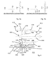
- Figures 3a and 3b respectively show a prior art arrangement and an arrangement according to the present invention with the additional fan.
- the boundary layer airflow below the dotted line will have 0.05 of the total mass flow at 0.8 of the free stream velocity relative to that located above the dotted line.
- a typical fan velocity ratio will be around 1.2.
- the energy input into the fan can be equated to the Delta kinetic energy of the flow.
- FIG. 4 Another embodiment of the propulsive system 410 on an aircraft 411 is shown in Figure 4 .
- the first 412 and second 414 propulsive fan units are located one on top of the other with respect to the surface 433 of the aircraft 411.
- the first propulsive unit 412 includes a first fan unit 416 having a plurality of blades 418 mounted on a rotatable hub 420 having a rotational axis 422.
- the rotatable hub 420 is mounted to and driven by an electrical machine drive 424.
- the drive 424, hub 420 and blades 418 are supported within a duct 426 by a plurality of struts 428.
- the duct 426 is bounded by a duct wall 429 and has an inlet 430 for receiving air and an outlet 432 for exhausting air and providing a propulsive force to the aircraft 11.
- the first propulsive unit 412 is mounted on a surface 433 of an aircraft 411 such that the lower parts of the duct 426 wall provide a continuation of the aircraft surface 433 and the upper parts define a nacelle 434 which provides support for the second propulsive unit 414.
- the duct 426 is dimensioned to provide a close fit for the rotational path of the fan blades 418 and may include abradable fan track liners and acoustic treatments as are known in the art but not shown here for the sake of clarity.
- the duct wall 429 can be located on a support structure such as a pylon.
- the inlet 430 is positioned such that the first fan unit 416 can ingest and accelerate so called boundary layer air.
- the boundary layer air is air which forms close to the surface 433 of an aircraft 411 and as such has a low flow velocity.
- the second propulsive unit 414 is similar to the first propulsive unit 412 in that it includes a second fan unit 436 having a plurality of blades 438 mounted on a rotatable hub 440.
- the rotational hub 440 has rotational axis 442 and is mounted to and driven by an electrical machine drive 444.
- the blades 438, hub 440 and drive 444 are all supported within a duct 446 by a plurality of struts 448.
- the duct 446 is bounded by a duct wall 450 which resides on top of the first propulsive unit 412 and defines a nacelle 458 and has an inlet 452 for receiving air and an outlet 454 for exhausting air and providing a propulsive force to the aircraft 411.
- the inlet 452 is positioned so as to predominantly ingest free flow air.
- the first propulsive unit 412 is located beneath the second propulsive unit 414 such that the wall which defines the duct of the first propulsive unit supports the second propulsive unit 414.
- the first propulsive unit 412 has a rotational axis 422 which is located proximate to the aircraft 411 relative to the rotational axis 442 of the second propulsive unit 414.
- the first fan unit 416 also has a smaller fan diameter which corresponds to the predominant flow depth of the boundary layer air in which it is located.
- the first propulsive unit 412 and second propulsive unit 414 are connected via a duct 460 which extends from the outlet of the first propulsive unit and enters the duct 460 of the second propulsive unit downstream of the second fan unit blades 438. In this way, the boundary layer is accelerated in use to a similar speed as the air flow produced by the second fan unit 436 without the pressure differential on the second fan unit 436.
- Figure 5 shows an axial series of cross sections, A to H at evenly spaced intervals along the principal axis 542 of the propulsive system and is a variant of the embodiment described in relation to Figure 4 .
- sections of two first propulsive units and a second propulsive unit which are arranged such that the outlets of the propulsive units are combined in a common duct.
- the two first propulsive units each include a first fan unit having a plurality of blades 518 mounted on a rotatable hub 520 having a rotational axis 522.
- the rotatable hub 520 is mounted to and driven by an electrical machine drive 524.
- the drive 524, hub 520 and blades 518 are supported within a duct 526 by a plurality of struts 528.
- the duct 526 is bounded by a duct wall and has an inlet 530 for receiving air and an outlet 532 for exhausting air and providing a propulsive force to the aircraft.
- the outlet 532 of the first fan unit is directed into the duct of the second propulsive unit 546 described below via a length of outlet duct 554 which is downstream of the fan 528.
- the first propulsive units are mounted symmetrically on either side of the second propulsive unit on a surface 533 of an aircraft 511 such that the lower parts of the duct 526 walls provide a continuation of the aircraft surface 533 and the exterior side walls define a nacelle 534.
- the upper surfaces of the ducts 526 provide wall sections 527 which partition the first and second propulsion units upstream of the fan units.
- the ducts 526 are dimensioned to provide a close fit for rotational path of the fan blades 518 at the portion which houses the fan blades and may include abradable fan track liners and acoustic treatments as are known in the art but not shown here for the sake of clarity.
- the second propulsive unit is similar to the first propulsive unit in that it includes a second fan unit having a plurality of blades 538 mounted on a rotatable hub 540.
- the rotatable hub 540 has rotational axis 542 and is mounted to and driven by an electrical machine drive 544.
- the blades 538, hub 540 and drive 544 are all supported within a duct 546 by a plurality of struts 548.
- the duct 546 is bounded by a duct wall in the form of a nacelle 558 on the upper portions and the partition wall 527 on the lower side, and has an inlet 552 for receiving air and an outlet for exhausting air and providing a propulsive force to the aircraft.
- the outlets of the first and second propulsive units are combined into a common duct which is downstream of the struts of the second propulsive unit.
- This is achieved by providing a duct 554 downstream of the first fan units which is initially coaxial with the upstream inlet duct 526.
- the downstream duct is separated from the duct 546 of the second propulsive unit by the partitioning wall 527 which includes an opening so as to expose it to and combine it with the outlet duct 546 of the second propulsive unit.
- the opening of the duct increases until the two ducts are combined into a single duct 547.
- the nacelle 558 which defines an inlet 552 for ingestion of air for the second propulsive unit.
- the inlet 552 is positioned so as to be separated from the upper surface 533 of the aircraft 511 and thus receive substantially free stream air when in normal use.
- the skilled person will appreciate that the separation of the nacelle 558 in this manner will be determined by the thickness of the boundary layer air which is to be ingested. This in turn will be dependent on the aircraft 511 and location of the inlet 552 on the aircraft.
- Beneath the second propulsive inlet are two inlets 530 which ingest air for the two first propulsive units.
- the inlets extend into respective ducts 526, 546.
- the second propulsive unit duct 546 is defined by the nacelle 558 and the partitioning walls 527 and leads to the fan blades 538 as shown at position D.
- the sides of the first propulsive unit inlets 526 are provided by walls 534 which extend perpendicularly from the upper surface 533 of the aircraft 211 to the underside of the nacelle 558.
- the inlets 530 extend into passageways 526 which are defined by the upper and side walls of the duct and upper surface 533 of the aircraft 511 and leads to the first propulsive fan unit.
- the ducts have morphed into a substantially circular shape having the rotatable hubs of 520 first fan units at their geometric centres.
- the first and second fan units are supported within their ducts 526, 546 via struts 528, 548 in the form of outlet guide vanes, as shown at position E. Downstream of the first fan units, the passageway extends into an outlet duct 554 which gradually opens out into the outlet duct of the second propulsive unit along the length of the duct 554 until a single circular duct is provided. It will be appreciated that as part of the morphing of the outlet ducts, the duct of the second propulsive unit may increase in diameter to provide a larger cross section. However, in other embodiments, it may not be necessary for the duct 446 to increase in diameter as the flow could already be accelerating towards the final nozzle.
- first and second fan units will be dependent on the required performance. This in turn is dependent on the aircraft on which they are employed and the nature of the boundary layer air which is being ingested.
- the design optimization between boundary layer re-acceleration and intake loss reduction would probably tend to locate the lip of the first fan's nacelle slightly inside the low speed region (and not at the 99% velocity boundary) so that shock losses may be reduced.
- a practical range of fan diameters might be considered as the first fan having a diameter in the range of between 35cm and 65cm and the second fan having a diameter in the range of between 200cm and 325cm.
- the ratio of the first fan unit diameter to the second fan unit diameter may be between approximately 0.12:1 and 0.3:1. It will be appreciated that these ranges may vary depending on the number installed and the aircraft design and the ratio may be as high as 0.4:1.
- a typical example would include a boundary layer air thickness at cruise (approximately 0.85 Mach) in the order of 38cm to 50cm at the rear of the fuselage of a large Blended Wing Body aircraft. Therefore, the smaller fan will have a size in the range between 38cm to 50cm, that is, approximately a similar size to the expected boundary layer thickness, and the larger fan will have a span in the range between 200cm and 325cm.
- the distance between first and second fans should be kept to a minimum, a sensible maximum being around twice the diameter of the second fan, but preferably within one fan diameter. This helps reduce the formation of boundary layer air downstream of the first fan unit, prior to entering the second fan unit.
- the embodiments refer to electrically driven fans, either or both of the propulsive units may be gas turbines, or driven by some other means such as hydraulically or pneumatically.
- the power required to drive one of the propulsive units may be taken from the other propulsive unit.
- the electrical power for driving the fan units in the described embodiment may be taken from one or more electrical sources.
- the aircraft may include one or more electrical generators powered by one or more gas turbine engines.
Landscapes
- Engineering & Computer Science (AREA)
- Aviation & Aerospace Engineering (AREA)
- Structures Of Non-Positive Displacement Pumps (AREA)
Abstract
Description
- This invention relates to a propulsive system for an aircraft. In particular, the invention relates to a propulsive system for ingestion of boundary layer air.
- Conventional state of the art propulsion systems for large civil aircraft typically include one or more gas turbine engines placed under the wings of the aircraft. However, some studies have indicated that so-called distributed propulsion, which involves having numerous smaller propulsion units preferentially arranged around an aircraft, may provide some significant benefits in terms of noise reduction and fuel efficiency when compared with the current state of the art propulsive arrangements.
- One known option for distributed propulsion is to provide numerous propulsive units which are located so as to capture and accelerate slow speed boundary layer air which has formed against the surface of the aircraft. This can lead to a significant reduction in overall fuel burn with the maximum benefit of boundary layer ingestion being achieved when the low speed flow is not mixed with the freestream flow, but is accelerated to homogeneous conditions by the propulsion system.
- However, delivering the required power at an acceptable level of efficiency by ingesting boundary layer air can be problematic for conventional propulsive systems, particularly where the propulsive unit is required to be larger than the thickness of the boundary layer air flow.
- The present invention seeks to provide an improved propulsive device for ingesting boundary layer air.
- In a first aspect, the present invention provides an aircraft comprising: a first propulsive unit having a first fan with an axis of rotation; and a second propulsive unit located so as to receive an airflow from the first propulsive unit, the second propulsive unit having a second fan with an axis of rotation, wherein the rotational axis of the first fan is proximate to the surface of the aircraft relative to the rotational axis of the second fan such that the first fan ingests boundary layer air when in use.
- Providing an arrangement according to the first aspect allows the propulsive units to ingest both boundary layer air and free stream air with a greater efficiency and also helps reduce vibration and mechanical wear in the propulsive system.
- The first and second propulsive units may be any one or more of: adjacent to one another; in a linear series; upstream and downstream and stacked one on top of the other; placed on a similar surface on the aircraft; and, separated by a dimension which is less than twice the diameter of the second fan. The second propulsive unit may be arranged so as to receive an airflow from an outlet of the first propulsive unit.
- The rotational axes may be in a common plane. The common plane may be vertical.
- There may be a plurality of first propulsion units for each second propulsive unit. The first propulsive units may be arranged across an inlet of the second propulsive unit.
- The diameter of the first fan may be smaller than that of the second fan. The first fan may have a diameter in the range of between 40cm and 62cm. The second fan may have a diameter in the range of between 200cm and 325cm. Hence, the ratio of the first fan diameter to the second fan diameter may be between approximately 0.12:1 and 0.3:1. It will be appreciated that these ranges may vary depending on the number installed and the aircraft design and the ratio may be up to 0.4:1.
- The first fan may be upstream of the second fan and accelerate boundary layer air for ingestion of the second fan.
- The second fan may be adjacent to a surface of the aircraft.
- The propulsive unit may further comprise a plurality of first propulsive units for each second propulsive unit.
- The outlet of the first propulsive unit may be ducted into the second propulsive unit downstream from the blades of the second fan.
- The axial separation between the outlet of the first and second fan may be a maximum of twice the second fan diameter.
- Embodiments of the invention will now be described with the following drawings in which:
-
Figure 1 shows a cross-sectional representation of a first arrangement according to the present invention. -
Figure 2 shows a non-orthogonal expanded axial series of cross sections at evenly spaced intervals along a principal axis of the aircraft propulsive system according to the invention. -
Figures 3a and 3b respectively show schematic representations of a prior art arrangement and an arrangement of the present invention. -
Figure 4 shows a cross-sectional representation of a second arrangement according to the present invention. -
Figure 5 shows a non-orthogonal expanded axial series of cross sections at evenly spaced intervals along a principal axis of the aircraft propulsive system according to the invention. -
Figure 1 shows apropulsive system 10 for anaircraft 11 comprising a firstpropulsive unit 12 and a secondpropulsive unit 14. - The first
propulsive unit 12 includes afirst fan unit 16 having a plurality ofblades 18 mounted on arotatable hub 20 having arotational axis 22. Therotatable hub 20 is mounted to and driven by anelectrical machine drive 24. Thedrive 24,hub 20 andblades 18 are supported within aduct 26 by a plurality ofstruts 28. Theduct 26 is bounded by aduct wall 29 and has aninlet 30 for receiving air and anoutlet 32 for exhausting air and providing a propulsive force to theaircraft 11. - The first
propulsive unit 12 is mounted on asurface 33 of anaircraft 11 such that the lower parts of theduct 26 wall provide a continuation of theaircraft surface 33 and the upper parts define anacelle 34. As will be appreciated, theduct 26 is dimensioned to provide a close fit for rotational path of thefan blades 18 and may include abradable fan track liners and acoustic treatments as are known in the art but not shown here for the sake of clarity. It will also be appreciated that, although incorporating theduct 26 into the surface of the aircraft so as to provide a smooth gas washed surface is advantageous, it is not a limitation of the invention and the duct wall can be located on a support structure such as a pylon. Further, it will also be appreciated that in this case, the term propulsive does not imply that the first unit exhausts an airflow which directly propels the aircraft. Nevertheless, the air accelerated by the first fan unit does act to propel the aircraft when in use, even if it is after the air has been further accelerated by the second propulsive unit. - The
inlet 30 is positioned such that thefirst fan unit 16 can ingest and accelerate so called boundary layer air. Boundary layer air is air which forms close to the surface of anaircraft 11 and as such has a low flow velocity. Boundary layer air on a conventional tube and wing aircraft is typically thickest towards the rear portions of the fuselage and the rearward portions of the wings. By referring to boundary layer air it will be understood that the term relates to a layer of air on a surface in contact with a moving fluid and may be defined as the portion of the flow near to the surface with a speed that is below 99% of the speed of an equivalent inviscid flow at the same location and conditions. When the velocity of the flow is above 99% of the inviscid case (e.g. almost unchanged) the flow is considered to be outside the boundary layer. Thickness of the boundary layer increases proportionally to the length of the surface it is flowing onto, as it is slowing down due to friction effects. - The second
propulsive unit 14 is similar to the firstpropulsive unit 12 in that it includes asecond fan unit 36 having a plurality ofblades 38 mounted on arotatable hub 40. Therotational hub 40 hasrotational axis 42 and is mounted to and driven by anelectrical machine drive 44. Theblades 38,hub 40 anddrive 44 are all supported within aduct 46 by a plurality ofstruts 48. Theduct 46 is bounded by aduct wall 50 and has aninlet 52 for receiving air and anoutlet 54 for exhausting air and providing a propulsive force to theaircraft 11. - The lower parts of the second propulsive
unit duct wall 50 provide a continuation of theaircraft surface 33 and the upper parts define anacelle 58. As will be appreciated, the secondpropulsive unit duct 46 is dimensioned to provide a close fit for the rotational path of thefan blades 38 and may include abradable fan track liners and acoustic treatments as are known in the art but not shown here for the sake of clarity. It will also be appreciated that, although incorporating theduct 46 into thesurface 33 of theaircraft 11 so as to provide a smooth gas washed surface is advantageous, it is not a limitation of the invention and theduct wall 50 can be located on a support structure such as a pylon. - The first
propulsive unit 12 is mounted upstream of the secondpropulsive unit 14 on thesurface 33 of theaircraft 11 with therotational axes propulsive unit 12 is smaller than the secondpropulsive unit 14 in that the diameter of thefirst fan unit 16 is smaller than the diameter of thesecond fan unit 36. This means that therotational axis 22 of thefirst fan unit 16 is proximate to thesurface 33 of theaircraft 11 relative to therotational axis 42 of the second fan unit. In other words, the inlet or nacelle ofpropulsive unit 12 is located closer tosurface 33 of theaircraft 11 such that it is substantially within the boundary layer air when in use. - In operation, the
aircraft 11 moves through the air from right to left with reference toFigure 1 such that an airflow is created from left to right which is ingested by thepropulsive units propulsive unit 12 ingests boundary layer air and accelerates it for ingestion by the secondpropulsive unit 14. The secondpropulsive unit 14 ingests air which has been accelerated by thefirst fan unit 16, and free flow air which passes over the firstpropulsive unit 12. In this way, the total pressure and velocity differential experienced across the span of the second fan units' 36fan blades 38 is reduced and the air which is ingested is more circumferentially homogenous. This helps reduce mechanical wear and vibrations on thesecond fan unit 36 which would be experienced if thefan 36 were to ingest both free flow air and un-accelerated boundary layer air. -
Figure 2 shows an axial series of cross sections, A to H at evenly spaced intervals along theprincipal axis 242 of the propulsive system. Hence, there is shown sections of the first propulsive unit, A to F, and a second propulsive, F to H, unit which are arranged in a series flow relationship such that air exiting the first propulsive unit enters the second propulsive unit. - The first propulsive unit includes a first fan unit having a plurality of
blades 218 mounted on arotatable hub 220 having arotational axis 222. Therotatable hub 220 is mounted to and driven by anelectrical machine drive 224. Thedrive 224,hub 220 andblades 218 are supported within aduct 226 by a plurality ofstruts 228. Theduct 226 is bounded by a duct wall and has aninlet 230 for receiving air and anoutlet 232 for exhausting air and providing a propulsive force to the aircraft. By propulsive force, it will be appreciated that this may not be a direct propulsive force as the outlet does not provide an airstream which directly exits the aircraft. Nevertheless, the air accelerated by the first fan unit does act to propel the aircraft when in use, even if it is after the air has been further accelerated by the second propulsive unit. - The first propulsive unit is mounted on a
surface 233 of an aircraft such that the lower parts of theduct 226 wall provide a continuation of theaircraft surface 233 and the side walls define anacelle 234. The upper surface of theduct 226 provides awall 227 which partitions the first and second propulsion units. As will be appreciated, theduct 226 is dimensioned to provide a close fit for rotational path of thefan blades 218 and may include abradable fan track liners and acoustic treatments as are known in the art but not shown here for the sake of clarity. - The second propulsive unit is similar to the first propulsive unit in that it includes a second fan unit having a plurality of
blades 238 mounted on arotatable hub 240. Therotatable hub 240 hasrotational axis 242 and is mounted to and driven by anelectrical machine drive 244. Theblades 238,hub 240 and drive 244 are all supported within aduct 246 by a plurality ofstruts 248. Theduct 246 is bounded by a duct wall in the form of anacelle 258 on the upper portions and thepartition wall 227 on the lower side, and has aninlet 252 for receiving air and an outlet (not shown) for exhausting air and providing a propulsive force to the aircraft. - In further detail, at point A, there is the
nacelle 258 which defines aninlet 252 for ingestion of air for the second propulsive unit. Theinlet 252 is positioned so as to be separated from theupper surface 233 of theaircraft 211 and thus receive substantially free stream air when in normal use. The skilled person will appreciate that the separation of thenacelle 258 in this manner will be determined by the thickness of the boundary layer air which is to be ingested by the first fan. This in turn will be dependent on theaircraft 211 and location of theinlet 252 on the aircraft. - The inlet extends into a
duct 246 which is defined by thenacelle 258 and thepartitioning wall 227 and leads to thefan blades 238 as shown at position G. At position B, there is shown the substantiallyrectangular inlet 230 to the first propulsive unit inlet located in the gap between thenacelle 258 and the upper surface of thewing 233. The sides of theinlet 230 are provided by walls which extend perpendicularly from the upper surface of theaircraft 211 to the underside of thenacelle 258. Theinlet 230 extends into apassageway 226 which is defined by the upper and side walls andupper surface 233 of theaircraft 211 and leads to the first propulsive fan unit. Hence, at position C, the duct has morphed into a substantially oval shape having the rotatinghub 220 of the first fan unit at its geometric centre. At stage C theduct 226 is circular in cross-section and houses therotatable fan blades 218 which are mounted to theelectric drive 224 so as to have therotational axis 222. - The first fan unit is supported within the
duct 226 viastruts 228 in the form of outlet guide vanes, as shown at Figure E. Downstream of the first fan unit, theduct 226 changes to anoutlet 232 which is a vesica piscis in shape. By vesica piscis it is meant a cusped or pointed oval having two arcuate sections of equal radii which are mirrored along a plane which extends along the major axis of the oval. However, it will be appreciated that the two arcuate sections may have different radii of curvature. Having a cusped oval for the outlet allows the accelerated air flow to be circumferentially distributed around thefan blades 238. - Also shown at section E is the
hub 240 of the second fan unit which occupies a central portion of the second unit'sduct 246. Therotating hub 240 is in the form of a cone and thus has a larger cross section at section G prior to the face of thefan 238 at section H. The fan face is positioned downstream of the cusped oval outlet such that it receives free stream air from thesecond duct 246 and accelerated air from thecusped outlet 232. Downstream of thefan blades 238 of the second propulsive unit are located thestruts 238 which support the fan unit within theduct 246 as shown inFigure 1 . - Hence, with the arrangement described in relation to
Figure 2 , there is primary propulsive unit for receiving freestream air and a smaller fan unit for accelerating the boundary layer air for ingestion by the primary propulsive unit. - A further benefit of the arrangement described in
Figures 1 and 2 is that it provides a more energy efficient propulsive system.Figures 3a and 3b respectively show a prior art arrangement and an arrangement according to the present invention with the additional fan. Typically, the boundary layer airflow below the dotted line will have 0.05 of the total mass flow at 0.8 of the free stream velocity relative to that located above the dotted line. For a low specific thrust a typical fan velocity ratio will be around 1.2. This gives rise to the following approximate relationships which are provided as a mere indication of the potential of the invention, using the mass and mean velocity notation denoted inFigure 3 :


- The energy input into the fan can be equated to the Delta kinetic energy of the flow. Hence:
- For the
Figure 3a arrangement:
- And for the
Figure 3b arrangement with the additional fan:
- Hence, the energy ratio between the two methods is 0.238/0.24=0.991 which is equivalent to 0.9% saving in energy by using the additional fan.
- Another embodiment of the
propulsive system 410 on anaircraft 411 is shown inFigure 4 . Here, the first 412 and second 414 propulsive fan units are located one on top of the other with respect to thesurface 433 of theaircraft 411. - The first
propulsive unit 412 includes afirst fan unit 416 having a plurality ofblades 418 mounted on arotatable hub 420 having arotational axis 422. Therotatable hub 420 is mounted to and driven by anelectrical machine drive 424. Thedrive 424,hub 420 andblades 418 are supported within aduct 426 by a plurality ofstruts 428. Theduct 426 is bounded by aduct wall 429 and has aninlet 430 for receiving air and anoutlet 432 for exhausting air and providing a propulsive force to theaircraft 11. - The first
propulsive unit 412 is mounted on asurface 433 of anaircraft 411 such that the lower parts of theduct 426 wall provide a continuation of theaircraft surface 433 and the upper parts define anacelle 434 which provides support for the secondpropulsive unit 414. As will be appreciated, theduct 426 is dimensioned to provide a close fit for the rotational path of thefan blades 418 and may include abradable fan track liners and acoustic treatments as are known in the art but not shown here for the sake of clarity. It will also be appreciated that, although incorporating theduct wall 429 into the surface of the aircraft so as to provide a smooth gas washed surface is advantageous, it is not a limitation of the invention and theduct wall 429 can be located on a support structure such as a pylon. - The
inlet 430 is positioned such that thefirst fan unit 416 can ingest and accelerate so called boundary layer air. The boundary layer air is air which forms close to thesurface 433 of anaircraft 411 and as such has a low flow velocity. - The second
propulsive unit 414 is similar to the firstpropulsive unit 412 in that it includes asecond fan unit 436 having a plurality ofblades 438 mounted on arotatable hub 440. Therotational hub 440 hasrotational axis 442 and is mounted to and driven by anelectrical machine drive 444. Theblades 438,hub 440 and drive 444 are all supported within aduct 446 by a plurality ofstruts 448. Theduct 446 is bounded by aduct wall 450 which resides on top of the firstpropulsive unit 412 and defines anacelle 458 and has aninlet 452 for receiving air and anoutlet 454 for exhausting air and providing a propulsive force to theaircraft 411. Theinlet 452 is positioned so as to predominantly ingest free flow air. - The first
propulsive unit 412 is located beneath the secondpropulsive unit 414 such that the wall which defines the duct of the first propulsive unit supports the secondpropulsive unit 414. Thus, the firstpropulsive unit 412 has arotational axis 422 which is located proximate to theaircraft 411 relative to therotational axis 442 of the secondpropulsive unit 414. Thefirst fan unit 416 also has a smaller fan diameter which corresponds to the predominant flow depth of the boundary layer air in which it is located. - The first
propulsive unit 412 and secondpropulsive unit 414 are connected via aduct 460 which extends from the outlet of the first propulsive unit and enters theduct 460 of the second propulsive unit downstream of the secondfan unit blades 438. In this way, the boundary layer is accelerated in use to a similar speed as the air flow produced by thesecond fan unit 436 without the pressure differential on thesecond fan unit 436. -
Figure 5 shows an axial series of cross sections, A to H at evenly spaced intervals along theprincipal axis 542 of the propulsive system and is a variant of the embodiment described in relation toFigure 4 . Hence, there are shown sections of two first propulsive units and a second propulsive unit which are arranged such that the outlets of the propulsive units are combined in a common duct. - The two first propulsive units each include a first fan unit having a plurality of
blades 518 mounted on arotatable hub 520 having arotational axis 522. Therotatable hub 520 is mounted to and driven by an electrical machine drive 524. The drive 524,hub 520 andblades 518 are supported within aduct 526 by a plurality ofstruts 528. Theduct 526 is bounded by a duct wall and has aninlet 530 for receiving air and anoutlet 532 for exhausting air and providing a propulsive force to the aircraft. Theoutlet 532 of the first fan unit is directed into the duct of the secondpropulsive unit 546 described below via a length ofoutlet duct 554 which is downstream of thefan 528. - The first propulsive units are mounted symmetrically on either side of the second propulsive unit on a
surface 533 of anaircraft 511 such that the lower parts of theduct 526 walls provide a continuation of theaircraft surface 533 and the exterior side walls define anacelle 534. The upper surfaces of theducts 526 providewall sections 527 which partition the first and second propulsion units upstream of the fan units. As will be appreciated, theducts 526 are dimensioned to provide a close fit for rotational path of thefan blades 518 at the portion which houses the fan blades and may include abradable fan track liners and acoustic treatments as are known in the art but not shown here for the sake of clarity. - The second propulsive unit is similar to the first propulsive unit in that it includes a second fan unit having a plurality of
blades 538 mounted on arotatable hub 540. Therotatable hub 540 hasrotational axis 542 and is mounted to and driven by anelectrical machine drive 544. Theblades 538,hub 540 and drive 544 are all supported within aduct 546 by a plurality ofstruts 548. Theduct 546 is bounded by a duct wall in the form of anacelle 558 on the upper portions and thepartition wall 527 on the lower side, and has aninlet 552 for receiving air and an outlet for exhausting air and providing a propulsive force to the aircraft. - In this embodiment, the outlets of the first and second propulsive units are combined into a common duct which is downstream of the struts of the second propulsive unit. This is achieved by providing a
duct 554 downstream of the first fan units which is initially coaxial with theupstream inlet duct 526. The downstream duct is separated from theduct 546 of the second propulsive unit by thepartitioning wall 527 which includes an opening so as to expose it to and combine it with theoutlet duct 546 of the second propulsive unit. The opening of the duct increases until the two ducts are combined into asingle duct 547. - In further detail, at point A, there is the
nacelle 558 which defines aninlet 552 for ingestion of air for the second propulsive unit. Theinlet 552 is positioned so as to be separated from theupper surface 533 of theaircraft 511 and thus receive substantially free stream air when in normal use. The skilled person will appreciate that the separation of thenacelle 558 in this manner will be determined by the thickness of the boundary layer air which is to be ingested. This in turn will be dependent on theaircraft 511 and location of theinlet 552 on the aircraft. Beneath the second propulsive inlet are twoinlets 530 which ingest air for the two first propulsive units. - The inlets extend into
respective ducts propulsive unit duct 546 is defined by thenacelle 558 and thepartitioning walls 527 and leads to thefan blades 538 as shown at position D. The sides of the firstpropulsive unit inlets 526 are provided bywalls 534 which extend perpendicularly from theupper surface 533 of theaircraft 211 to the underside of thenacelle 558. Theinlets 530 extend intopassageways 526 which are defined by the upper and side walls of the duct andupper surface 533 of theaircraft 511 and leads to the first propulsive fan unit. Hence, at position D, the ducts have morphed into a substantially circular shape having the rotatable hubs of 520 first fan units at their geometric centres. - The first and second fan units are supported within their
ducts struts outlet duct 554 which gradually opens out into the outlet duct of the second propulsive unit along the length of theduct 554 until a single circular duct is provided. It will be appreciated that as part of the morphing of the outlet ducts, the duct of the second propulsive unit may increase in diameter to provide a larger cross section. However, in other embodiments, it may not be necessary for theduct 446 to increase in diameter as the flow could already be accelerating towards the final nozzle. - The skilled person will appreciate that the positioning and size of the first and second fan units will be dependent on the required performance. This in turn is dependent on the aircraft on which they are employed and the nature of the boundary layer air which is being ingested. The design optimization between boundary layer re-acceleration and intake loss reduction would probably tend to locate the lip of the first fan's nacelle slightly inside the low speed region (and not at the 99% velocity boundary) so that shock losses may be reduced. A practical range of fan diameters might be considered as the first fan having a diameter in the range of between 35cm and 65cm and the second fan having a diameter in the range of between 200cm and 325cm. Hence, the ratio of the first fan unit diameter to the second fan unit diameter may be between approximately 0.12:1 and 0.3:1. It will be appreciated that these ranges may vary depending on the number installed and the aircraft design and the ratio may be as high as 0.4:1.
- A typical example would include a boundary layer air thickness at cruise (approximately 0.85 Mach) in the order of 38cm to 50cm at the rear of the fuselage of a large Blended Wing Body aircraft. Therefore, the smaller fan will have a size in the range between 38cm to 50cm, that is, approximately a similar size to the expected boundary layer thickness, and the larger fan will have a span in the range between 200cm and 325cm. The distance between first and second fans should be kept to a minimum, a sensible maximum being around twice the diameter of the second fan, but preferably within one fan diameter. This helps reduce the formation of boundary layer air downstream of the first fan unit, prior to entering the second fan unit.
- The scope of the invention is defined by the claims and the above embodiments should not be taken as limitations of the claimed invention. For example, although the embodiments refer to electrically driven fans, either or both of the propulsive units may be gas turbines, or driven by some other means such as hydraulically or pneumatically. The power required to drive one of the propulsive units may be taken from the other propulsive unit. The electrical power for driving the fan units in the described embodiment may be taken from one or more electrical sources. For example, the aircraft may include one or more electrical generators powered by one or more gas turbine engines.
Claims (8)
- An aircraft comprising:a first propulsive unit having a first fan with an axis of rotation; anda second propulsive unit located so as to receive an airflow from the first propulsive unit, the second propulsive unit having a second fan with an axis of rotation,wherein the rotational axis of the first fan is proximate to the surface of the aircraft relative to the rotational axis of the second fan such that the first fan ingests boundary layer air when in use.
- An aircraft as claimed in claim 1, wherein the diameter of the first fan is smaller than that of the second fan.
- An aircraft as claimed in either of claims 1 or 2, wherein the first fan is upstream of the second fan and accelerates boundary layer air for ingestion of the second fan.
- An aircraft as claimed in any preceding claim wherein the second fan is adjacent to a surface of the aircraft.
- An aircraft as claimed in any preceding claim further comprising a plurality of first propulsive units for each second propulsive unit.
- An aircraft as claimed in any of claims 1, 2, 4 and 5, wherein the outlet of the first propulsive unit is ducted into the second propulsive unit downstream from the blades of the second fan.
- An aircraft as claimed in any preceding claim wherein the ratio of the first fan unit diameter to the second fan unit diameter is between 0.12:1 and 0.4:1.
- An aircraft as claimed in any preceding claim wherein the axial separation between the outlet of the first and second fan is a maximum of twice the second fan diameter.
Applications Claiming Priority (1)
| Application Number | Priority Date | Filing Date | Title |
|---|---|---|---|
| GBGB1118289.6A GB201118289D0 (en) | 2011-10-24 | 2011-10-24 | A propulsive system |
Publications (2)
| Publication Number | Publication Date |
|---|---|
| EP2586706A1 true EP2586706A1 (en) | 2013-05-01 |
| EP2586706B1 EP2586706B1 (en) | 2016-03-23 |
Family
ID=45373290
Family Applications (1)
| Application Number | Title | Priority Date | Filing Date |
|---|---|---|---|
| EP12187090.1A Not-in-force EP2586706B1 (en) | 2011-10-24 | 2012-10-03 | A propulsive system |
Country Status (3)
| Country | Link |
|---|---|
| US (1) | US9266617B2 (en) |
| EP (1) | EP2586706B1 (en) |
| GB (1) | GB201118289D0 (en) |
Families Citing this family (4)
| Publication number | Priority date | Publication date | Assignee | Title |
|---|---|---|---|---|
| WO2020142332A1 (en) * | 2018-12-31 | 2020-07-09 | DZYNE Technologies Incorporated | Drag recovery scheme for nacelles |
| CN115583336A (en) * | 2021-07-05 | 2023-01-10 | 中国航发商用航空发动机有限责任公司 | Fan assembly and aircraft containing it |
| CN115583335B (en) * | 2021-07-05 | 2025-08-01 | 中国航发商用航空发动机有限责任公司 | Loss reducing device, boundary layer suction fan and aircraft |
| US11827339B1 (en) * | 2023-01-27 | 2023-11-28 | Jetzero, Inc. | Apparatus for ingesting boundary layer flow for an aircraft |
Citations (5)
| Publication number | Priority date | Publication date | Assignee | Title |
|---|---|---|---|---|
| FR640855A (en) * | 1927-02-22 | 1928-07-24 | New engine arrangement on any aircraft having more than four engines | |
| AU532184B2 (en) * | 1979-03-05 | 1983-09-22 | Rotary-Engine Kenkyusho | Compound rotorcraft |
| GB2433733A (en) * | 2005-12-31 | 2007-07-04 | Peter Roger Julien Robe Bisson | Aeroplane propulsion system |
| DE102008027275A1 (en) * | 2008-06-06 | 2010-01-07 | Atena Engineering Gmbh | Air-breathing nacelle for aircraft engine, has circular front contour and sucking unit that is provided for sucking air into nacelle, where sucking unit comprises turbocharger with fan and turbine |
| US20110168835A1 (en) * | 2009-10-09 | 2011-07-14 | Richard David Oliver | Three Wing, Six Tilt-Propulsion Units, VTOL Aircraft |
Family Cites Families (6)
| Publication number | Priority date | Publication date | Assignee | Title |
|---|---|---|---|---|
| GB974384A (en) | 1962-10-29 | 1964-11-04 | Messerschmitt Ag | An arrangement of turbo jet engines at the tail end of an aircraft |
| GB1024894A (en) | 1963-05-16 | 1966-04-06 | Vickers Armstrongs Aircraft | Improvements in aircraft jet-propulsion power-plants |
| FR1443200A (en) | 1965-04-21 | 1966-06-24 | Bristol Siddeley Engines Ltd | Powerplant using a gas turbine, for aircraft |
| GB2359052B (en) * | 2000-02-09 | 2003-09-17 | Rolls Royce Plc | Engine arrangement |
| US7784732B2 (en) | 2007-01-04 | 2010-08-31 | The United States Of America As Represented By The Administrator Of The National Aeronautics And Space Administration | Boundary-layer-ingesting inlet flow control system |
| DE102008024463B4 (en) | 2008-05-21 | 2011-02-24 | Bauhaus Luftfahrt E.V. | Aircraft Drive System |
-
2011
- 2011-10-24 GB GBGB1118289.6A patent/GB201118289D0/en not_active Ceased
-
2012
- 2012-10-03 EP EP12187090.1A patent/EP2586706B1/en not_active Not-in-force
- 2012-10-04 US US13/644,509 patent/US9266617B2/en not_active Expired - Fee Related
Patent Citations (5)
| Publication number | Priority date | Publication date | Assignee | Title |
|---|---|---|---|---|
| FR640855A (en) * | 1927-02-22 | 1928-07-24 | New engine arrangement on any aircraft having more than four engines | |
| AU532184B2 (en) * | 1979-03-05 | 1983-09-22 | Rotary-Engine Kenkyusho | Compound rotorcraft |
| GB2433733A (en) * | 2005-12-31 | 2007-07-04 | Peter Roger Julien Robe Bisson | Aeroplane propulsion system |
| DE102008027275A1 (en) * | 2008-06-06 | 2010-01-07 | Atena Engineering Gmbh | Air-breathing nacelle for aircraft engine, has circular front contour and sucking unit that is provided for sucking air into nacelle, where sucking unit comprises turbocharger with fan and turbine |
| US20110168835A1 (en) * | 2009-10-09 | 2011-07-14 | Richard David Oliver | Three Wing, Six Tilt-Propulsion Units, VTOL Aircraft |
Also Published As
| Publication number | Publication date |
|---|---|
| EP2586706B1 (en) | 2016-03-23 |
| GB201118289D0 (en) | 2011-12-07 |
| US20130101392A1 (en) | 2013-04-25 |
| US9266617B2 (en) | 2016-02-23 |
Similar Documents
| Publication | Publication Date | Title |
|---|---|---|
| US20220234746A1 (en) | Gas-Electric Propulsion System for an Aircraft | |
| EP2098714B1 (en) | High bypass-ratio turbofan jet engine | |
| US9644537B2 (en) | Free stream intake with particle separator for reverse core engine | |
| EP2597037A2 (en) | An Aircraft | |
| US20130306024A1 (en) | Duct | |
| US9534497B2 (en) | Inter-turbine ducts with variable area ratios | |
| JP2016211576A (en) | Immersed core flow inlet between rotor blade and stator vane for unducted fan gas turbine | |
| JP2016505434A (en) | Aircraft propelled by turbojet engine with counter rotating fan | |
| US8845286B2 (en) | Inter-turbine ducts with guide vanes | |
| US11131205B2 (en) | Inter-turbine ducts with flow control mechanisms | |
| JPS58149898A (en) | Engine for propelling prop fan type aircraft | |
| EP3293355A1 (en) | Rotor stage | |
| CN108327915A (en) | Cabin for aircraft rear fan | |
| EP2586706B1 (en) | A propulsive system | |
| CN118223957A (en) | Turbofan engine outlet guide vane assembly | |
| US20130134265A1 (en) | Aircraft | |
| US10519976B2 (en) | Fluid diodes with ridges to control boundary layer in axial compressor stator vane | |
| JP2001207911A (en) | Duct device for gas turbine engine | |
| US10787270B2 (en) | Propulsor |
Legal Events
| Date | Code | Title | Description |
|---|---|---|---|
| PUAI | Public reference made under article 153(3) epc to a published international application that has entered the european phase |
Free format text: ORIGINAL CODE: 0009012 |
|
| AK | Designated contracting states |
Kind code of ref document: A1 Designated state(s): AL AT BE BG CH CY CZ DE DK EE ES FI FR GB GR HR HU IE IS IT LI LT LU LV MC MK MT NL NO PL PT RO RS SE SI SK SM TR |
|
| AX | Request for extension of the european patent |
Extension state: BA ME |
|
| 17P | Request for examination filed |
Effective date: 20131030 |
|
| RBV | Designated contracting states (corrected) |
Designated state(s): AL AT BE BG CH CY CZ DE DK EE ES FI FR GB GR HR HU IE IS IT LI LT LU LV MC MK MT NL NO PL PT RO RS SE SI SK SM TR |
|
| RAP1 | Party data changed (applicant data changed or rights of an application transferred) |
Owner name: ROLLS-ROYCE PLC |
|
| GRAP | Despatch of communication of intention to grant a patent |
Free format text: ORIGINAL CODE: EPIDOSNIGR1 |
|
| INTG | Intention to grant announced |
Effective date: 20151217 |
|
| GRAS | Grant fee paid |
Free format text: ORIGINAL CODE: EPIDOSNIGR3 |
|
| GRAA | (expected) grant |
Free format text: ORIGINAL CODE: 0009210 |
|
| AK | Designated contracting states |
Kind code of ref document: B1 Designated state(s): AL AT BE BG CH CY CZ DE DK EE ES FI FR GB GR HR HU IE IS IT LI LT LU LV MC MK MT NL NO PL PT RO RS SE SI SK SM TR |
|
| REG | Reference to a national code |
Ref country code: GB Ref legal event code: FG4D |
|
| REG | Reference to a national code |
Ref country code: CH Ref legal event code: EP |
|
| REG | Reference to a national code |
Ref country code: AT Ref legal event code: REF Ref document number: 782882 Country of ref document: AT Kind code of ref document: T Effective date: 20160415 |
|
| REG | Reference to a national code |
Ref country code: IE Ref legal event code: FG4D |
|
| REG | Reference to a national code |
Ref country code: DE Ref legal event code: R096 Ref document number: 602012015883 Country of ref document: DE |
|
| REG | Reference to a national code |
Ref country code: LT Ref legal event code: MG4D |
|
| REG | Reference to a national code |
Ref country code: NL Ref legal event code: MP Effective date: 20160323 |
|
| PG25 | Lapsed in a contracting state [announced via postgrant information from national office to epo] |
Ref country code: GR Free format text: LAPSE BECAUSE OF FAILURE TO SUBMIT A TRANSLATION OF THE DESCRIPTION OR TO PAY THE FEE WITHIN THE PRESCRIBED TIME-LIMIT Effective date: 20160624 Ref country code: NO Free format text: LAPSE BECAUSE OF FAILURE TO SUBMIT A TRANSLATION OF THE DESCRIPTION OR TO PAY THE FEE WITHIN THE PRESCRIBED TIME-LIMIT Effective date: 20160623 Ref country code: HR Free format text: LAPSE BECAUSE OF FAILURE TO SUBMIT A TRANSLATION OF THE DESCRIPTION OR TO PAY THE FEE WITHIN THE PRESCRIBED TIME-LIMIT Effective date: 20160323 Ref country code: FI Free format text: LAPSE BECAUSE OF FAILURE TO SUBMIT A TRANSLATION OF THE DESCRIPTION OR TO PAY THE FEE WITHIN THE PRESCRIBED TIME-LIMIT Effective date: 20160323 |
|
| REG | Reference to a national code |
Ref country code: AT Ref legal event code: MK05 Ref document number: 782882 Country of ref document: AT Kind code of ref document: T Effective date: 20160323 |
|
| PG25 | Lapsed in a contracting state [announced via postgrant information from national office to epo] |
Ref country code: RS Free format text: LAPSE BECAUSE OF FAILURE TO SUBMIT A TRANSLATION OF THE DESCRIPTION OR TO PAY THE FEE WITHIN THE PRESCRIBED TIME-LIMIT Effective date: 20160323 Ref country code: SE Free format text: LAPSE BECAUSE OF FAILURE TO SUBMIT A TRANSLATION OF THE DESCRIPTION OR TO PAY THE FEE WITHIN THE PRESCRIBED TIME-LIMIT Effective date: 20160323 Ref country code: LT Free format text: LAPSE BECAUSE OF FAILURE TO SUBMIT A TRANSLATION OF THE DESCRIPTION OR TO PAY THE FEE WITHIN THE PRESCRIBED TIME-LIMIT Effective date: 20160323 Ref country code: LV Free format text: LAPSE BECAUSE OF FAILURE TO SUBMIT A TRANSLATION OF THE DESCRIPTION OR TO PAY THE FEE WITHIN THE PRESCRIBED TIME-LIMIT Effective date: 20160323 Ref country code: NL Free format text: LAPSE BECAUSE OF FAILURE TO SUBMIT A TRANSLATION OF THE DESCRIPTION OR TO PAY THE FEE WITHIN THE PRESCRIBED TIME-LIMIT Effective date: 20160323 |
|
| REG | Reference to a national code |
Ref country code: FR Ref legal event code: PLFP Year of fee payment: 5 |
|
| PG25 | Lapsed in a contracting state [announced via postgrant information from national office to epo] |
Ref country code: IS Free format text: LAPSE BECAUSE OF FAILURE TO SUBMIT A TRANSLATION OF THE DESCRIPTION OR TO PAY THE FEE WITHIN THE PRESCRIBED TIME-LIMIT Effective date: 20160723 Ref country code: EE Free format text: LAPSE BECAUSE OF FAILURE TO SUBMIT A TRANSLATION OF THE DESCRIPTION OR TO PAY THE FEE WITHIN THE PRESCRIBED TIME-LIMIT Effective date: 20160323 Ref country code: PL Free format text: LAPSE BECAUSE OF FAILURE TO SUBMIT A TRANSLATION OF THE DESCRIPTION OR TO PAY THE FEE WITHIN THE PRESCRIBED TIME-LIMIT Effective date: 20160323 |
|
| PG25 | Lapsed in a contracting state [announced via postgrant information from national office to epo] |
Ref country code: SK Free format text: LAPSE BECAUSE OF FAILURE TO SUBMIT A TRANSLATION OF THE DESCRIPTION OR TO PAY THE FEE WITHIN THE PRESCRIBED TIME-LIMIT Effective date: 20160323 Ref country code: ES Free format text: LAPSE BECAUSE OF FAILURE TO SUBMIT A TRANSLATION OF THE DESCRIPTION OR TO PAY THE FEE WITHIN THE PRESCRIBED TIME-LIMIT Effective date: 20160323 Ref country code: AT Free format text: LAPSE BECAUSE OF FAILURE TO SUBMIT A TRANSLATION OF THE DESCRIPTION OR TO PAY THE FEE WITHIN THE PRESCRIBED TIME-LIMIT Effective date: 20160323 Ref country code: RO Free format text: LAPSE BECAUSE OF FAILURE TO SUBMIT A TRANSLATION OF THE DESCRIPTION OR TO PAY THE FEE WITHIN THE PRESCRIBED TIME-LIMIT Effective date: 20160323 Ref country code: CZ Free format text: LAPSE BECAUSE OF FAILURE TO SUBMIT A TRANSLATION OF THE DESCRIPTION OR TO PAY THE FEE WITHIN THE PRESCRIBED TIME-LIMIT Effective date: 20160323 Ref country code: PT Free format text: LAPSE BECAUSE OF FAILURE TO SUBMIT A TRANSLATION OF THE DESCRIPTION OR TO PAY THE FEE WITHIN THE PRESCRIBED TIME-LIMIT Effective date: 20160725 Ref country code: SM Free format text: LAPSE BECAUSE OF FAILURE TO SUBMIT A TRANSLATION OF THE DESCRIPTION OR TO PAY THE FEE WITHIN THE PRESCRIBED TIME-LIMIT Effective date: 20160323 |
|
| PG25 | Lapsed in a contracting state [announced via postgrant information from national office to epo] |
Ref country code: IT Free format text: LAPSE BECAUSE OF FAILURE TO SUBMIT A TRANSLATION OF THE DESCRIPTION OR TO PAY THE FEE WITHIN THE PRESCRIBED TIME-LIMIT Effective date: 20160323 Ref country code: BE Free format text: LAPSE BECAUSE OF FAILURE TO SUBMIT A TRANSLATION OF THE DESCRIPTION OR TO PAY THE FEE WITHIN THE PRESCRIBED TIME-LIMIT Effective date: 20160323 |
|
| REG | Reference to a national code |
Ref country code: DE Ref legal event code: R097 Ref document number: 602012015883 Country of ref document: DE |
|
| PLBE | No opposition filed within time limit |
Free format text: ORIGINAL CODE: 0009261 |
|
| STAA | Information on the status of an ep patent application or granted ep patent |
Free format text: STATUS: NO OPPOSITION FILED WITHIN TIME LIMIT |
|
| PG25 | Lapsed in a contracting state [announced via postgrant information from national office to epo] |
Ref country code: DK Free format text: LAPSE BECAUSE OF FAILURE TO SUBMIT A TRANSLATION OF THE DESCRIPTION OR TO PAY THE FEE WITHIN THE PRESCRIBED TIME-LIMIT Effective date: 20160323 |
|
| PG25 | Lapsed in a contracting state [announced via postgrant information from national office to epo] |
Ref country code: BG Free format text: LAPSE BECAUSE OF FAILURE TO SUBMIT A TRANSLATION OF THE DESCRIPTION OR TO PAY THE FEE WITHIN THE PRESCRIBED TIME-LIMIT Effective date: 20160623 |
|
| 26N | No opposition filed |
Effective date: 20170102 |
|
| PG25 | Lapsed in a contracting state [announced via postgrant information from national office to epo] |
Ref country code: SI Free format text: LAPSE BECAUSE OF FAILURE TO SUBMIT A TRANSLATION OF THE DESCRIPTION OR TO PAY THE FEE WITHIN THE PRESCRIBED TIME-LIMIT Effective date: 20160323 |
|
| REG | Reference to a national code |
Ref country code: CH Ref legal event code: PL |
|
| REG | Reference to a national code |
Ref country code: IE Ref legal event code: MM4A |
|
| PG25 | Lapsed in a contracting state [announced via postgrant information from national office to epo] |
Ref country code: LI Free format text: LAPSE BECAUSE OF NON-PAYMENT OF DUE FEES Effective date: 20161031 Ref country code: CH Free format text: LAPSE BECAUSE OF NON-PAYMENT OF DUE FEES Effective date: 20161031 |
|
| PG25 | Lapsed in a contracting state [announced via postgrant information from national office to epo] |
Ref country code: LU Free format text: LAPSE BECAUSE OF NON-PAYMENT OF DUE FEES Effective date: 20161003 |
|
| REG | Reference to a national code |
Ref country code: FR Ref legal event code: PLFP Year of fee payment: 6 |
|
| PG25 | Lapsed in a contracting state [announced via postgrant information from national office to epo] |
Ref country code: IE Free format text: LAPSE BECAUSE OF NON-PAYMENT OF DUE FEES Effective date: 20161003 |
|
| PG25 | Lapsed in a contracting state [announced via postgrant information from national office to epo] |
Ref country code: CY Free format text: LAPSE BECAUSE OF FAILURE TO SUBMIT A TRANSLATION OF THE DESCRIPTION OR TO PAY THE FEE WITHIN THE PRESCRIBED TIME-LIMIT Effective date: 20160323 Ref country code: HU Free format text: LAPSE BECAUSE OF FAILURE TO SUBMIT A TRANSLATION OF THE DESCRIPTION OR TO PAY THE FEE WITHIN THE PRESCRIBED TIME-LIMIT; INVALID AB INITIO Effective date: 20121003 |
|
| PG25 | Lapsed in a contracting state [announced via postgrant information from national office to epo] |
Ref country code: MK Free format text: LAPSE BECAUSE OF FAILURE TO SUBMIT A TRANSLATION OF THE DESCRIPTION OR TO PAY THE FEE WITHIN THE PRESCRIBED TIME-LIMIT Effective date: 20160323 Ref country code: MC Free format text: LAPSE BECAUSE OF FAILURE TO SUBMIT A TRANSLATION OF THE DESCRIPTION OR TO PAY THE FEE WITHIN THE PRESCRIBED TIME-LIMIT Effective date: 20160323 Ref country code: TR Free format text: LAPSE BECAUSE OF FAILURE TO SUBMIT A TRANSLATION OF THE DESCRIPTION OR TO PAY THE FEE WITHIN THE PRESCRIBED TIME-LIMIT Effective date: 20160323 Ref country code: MT Free format text: LAPSE BECAUSE OF NON-PAYMENT OF DUE FEES Effective date: 20161031 |
|
| REG | Reference to a national code |
Ref country code: FR Ref legal event code: PLFP Year of fee payment: 7 |
|
| PG25 | Lapsed in a contracting state [announced via postgrant information from national office to epo] |
Ref country code: AL Free format text: LAPSE BECAUSE OF FAILURE TO SUBMIT A TRANSLATION OF THE DESCRIPTION OR TO PAY THE FEE WITHIN THE PRESCRIBED TIME-LIMIT Effective date: 20160323 |
|
| PGFP | Annual fee paid to national office [announced via postgrant information from national office to epo] |
Ref country code: FR Payment date: 20221024 Year of fee payment: 11 |
|
| PGFP | Annual fee paid to national office [announced via postgrant information from national office to epo] |
Ref country code: GB Payment date: 20221018 Year of fee payment: 11 Ref country code: DE Payment date: 20221028 Year of fee payment: 11 |
|
| P01 | Opt-out of the competence of the unified patent court (upc) registered |
Effective date: 20230528 |
|
| REG | Reference to a national code |
Ref country code: DE Ref legal event code: R119 Ref document number: 602012015883 Country of ref document: DE |
|
| GBPC | Gb: european patent ceased through non-payment of renewal fee |
Effective date: 20231003 |
|
| PG25 | Lapsed in a contracting state [announced via postgrant information from national office to epo] |
Ref country code: GB Free format text: LAPSE BECAUSE OF NON-PAYMENT OF DUE FEES Effective date: 20231003 |
|
| PG25 | Lapsed in a contracting state [announced via postgrant information from national office to epo] |
Ref country code: GB Free format text: LAPSE BECAUSE OF NON-PAYMENT OF DUE FEES Effective date: 20231003 Ref country code: FR Free format text: LAPSE BECAUSE OF NON-PAYMENT OF DUE FEES Effective date: 20231031 Ref country code: DE Free format text: LAPSE BECAUSE OF NON-PAYMENT OF DUE FEES Effective date: 20240501 |