EP2586653A1 - Vehicle seat mounting structure - Google Patents
Vehicle seat mounting structure Download PDFInfo
- Publication number
- EP2586653A1 EP2586653A1 EP11797905.4A EP11797905A EP2586653A1 EP 2586653 A1 EP2586653 A1 EP 2586653A1 EP 11797905 A EP11797905 A EP 11797905A EP 2586653 A1 EP2586653 A1 EP 2586653A1
- Authority
- EP
- European Patent Office
- Prior art keywords
- wall
- leg
- seat
- vehicle
- bushes
- Prior art date
- Legal status (The legal status is an assumption and is not a legal conclusion. Google has not performed a legal analysis and makes no representation as to the accuracy of the status listed.)
- Granted
Links
Images




Classifications
-
- B—PERFORMING OPERATIONS; TRANSPORTING
- B60—VEHICLES IN GENERAL
- B60N—SEATS SPECIALLY ADAPTED FOR VEHICLES; VEHICLE PASSENGER ACCOMMODATION NOT OTHERWISE PROVIDED FOR
- B60N2/00—Seats specially adapted for vehicles; Arrangement or mounting of seats in vehicles
- B60N2/005—Arrangement or mounting of seats in vehicles, e.g. dismountable auxiliary seats
- B60N2/015—Attaching seats directly to vehicle chassis
-
- B—PERFORMING OPERATIONS; TRANSPORTING
- B60—VEHICLES IN GENERAL
- B60N—SEATS SPECIALLY ADAPTED FOR VEHICLES; VEHICLE PASSENGER ACCOMMODATION NOT OTHERWISE PROVIDED FOR
- B60N2/00—Seats specially adapted for vehicles; Arrangement or mounting of seats in vehicles
- B60N2/68—Seat frames
- B60N2/682—Joining means
Definitions
- the present invention relates to a vehicle seat mounting structure.
- a vehicle seat mounting structure for a vehicle seat 201 (e.g., a right rear seat of a van type vehicle) has already been known.
- legs 230 are secured to a seat cushion 202.
- Each of the legs 230 is formed as a substantially rectangular tube by four walls of a first wall 240, a second wall 242, a third wall 244 and a fourth wall 246.
- the first wall 240 facing a vehicle floor 260 and the second wall 242 facing the first wall 240 are fastened together to the vehicle floor 260 via bolts 270 and nuts 272.
- substantially tubular metal bushes 250 are positioned in each of the legs 230 such that the bolts 270 can be inserted thereinto.
- Patent Document 1 is known as a prior art document containing information related to the invention of this application.
- each of the bushes 250 are arranged so as to penetrate the legs 230 in an inserting direction of the bolts 270.
- each of the bushes 250 may have two welding portions bonding the bushes 250 to the legs 230 (i.e., a welding portion between one axial end of each of the bushes 250 and the first wall 240 of each of the legs 230, and a welding portion between the other axial end of each of the bushes 250 and the second wall 242 of each of the legs 230, which welding portions are respectively shown by a and b in FIG. 8 and 9 ).
- the latter welding portion (the welding portion shown by b in FIGS. 8 and 9 ) may be exposed. This may lead to an inferior appearance of each of mounting portions of the vehicle seat 201.
- the present invention has been made in order to solve the problems described above. Accordingly, it is an object of the present invention to provide a structure in which when a leg is fastened together to the vehicle floor via bolts and nuts in order to mount a vehicle seat on a vehicle floor, the leg can be prevented from being crushed without deteriorating an appearance of each of mounting portions.
- the present invention may provide a vehicle seat mounting structure in which a leg is secured to a seat cushion and is formed as a substantially rectangular tube by four walls of a first wall, a second wall, a third wall and a fourth wall, in which the first wall facing a vehicle floor and the second wall facing the first wall are fastened together to the vehicle floor via a bolt and a nut, and in which a substantially tubular metal bush capable of preventing the leg from being crushed by the fastening-together action is positioned in the leg such that the bolt can be inserted thereinto, wherein the bush has a flange that is formed in a periphery of one axial end thereof, wherein the flange is interleaved between the first wall of the leg and the vehicle floor, and wherein the second wall of the leg is interleaved between a head portion of the bolt and the other axial end of the bush.
- the flange of the bush and the first wall of the leg may be bonded to each other by welding.
- the vehicle seat can be mounted on the vehicle floor while the bush is secured to the leg.
- workability of mounting can be increased.
- a right rear seat 1 of a van type vehicle will be exemplified as “a vehicle seat.”
- upward and downward, forward and backward, and rightward and leftward in the description respectively correspond to upward and downward, forward and backward, and rightward and leftward in the drawings described above, i.e., upward and downward, forward and backward, and rightward and leftward with respect to the right rear seat 1.
- Embodiment 1 of the present invention will be described with reference to FIGS. 1 to 3 .
- a structure of the right rear seat 1 according to Embodiment 1 will be schematically described with reference to FIG. 1 .
- the right rear seat 1 is a seat for two people and is composed of a seat cushion 2 and a seatback (not shown). Of the seat cushion 2 and the seatback, the seat cushion 2 will be described in detail.
- the seatback may have a well-known structure, a detailed description thereof may be omitted. Further, in FIG. 1 , a cushion pad and a seat cover are omitted such that an internal structure of the seat cushion of the right rear seat 1 may be clearly seen. This may apply in Embodiment 2 described below.
- the seat cushion 2 is composed of a cushion frame 10, a well-known cushion pad (not shown) attached to the cushion frame 10 while wrapping around the same, and a well-known seat cover (not shown) that covers a surface of the cushion pad.
- the cushion frame 10 is mainly composed of a frame main body 20 and a leg 30. In the following, the frame main body 20 and the leg 30 will be individually described.
- the frame main body 20 is a member forming a framework of the seat cushion 2 and is formed as a rectangular frame.
- the rectangular frame has a plurality of springs 22 --- 22 that are positioned therein so as to extend back and forth thereof.
- the seat cushion 2 may be comfortable to sit on for an occupant.
- the frame main body 20 has brackets 24 and 26 that are respectively secured to front and rear ends thereof in an outer side thereof (a right side in FIG. 1 ) in order to connect the same to a right inner wall 64 of the vehicle.
- the leg 30 is a member for connecting the seat cushion 2 to a vehicle floor 60 and is formed so as to have a substantially U-shape.
- the leg 30 is formed as a substantially rectangular tube that is constructed of a first wall 40, a second wall 42, a third wall 44 and a fourth wall 46 ( FIG. 3 ).
- a side having no free end (a bottom side in FIG. 1 which will be hereinafter referred to as "a base side 32") has a pair of front and rear through-holes 40a and 42a that are formed therethrough in a thickness direction thereof.
- the first wall 40 (a lower wall in FIGS. 1 to 3 ) of the base side 32 has a pair of front and rear mounting holes 40a and 40a that are formed therethrough in a thickness direction thereof.
- the mounting holes 40a are configured such that bushes 50, which will be hereinafter described, can be inserted thereinto.
- a diameter of each of the mounting holes 40a may be referred to as "D1.”
- the second wall 42 (an upper wall in FIGS. 1 to 3 ) of the base side 32 also has a pair of front and rear mounting holes 42a and 42a that are formed therethrough in a thickness direction thereof.
- the mounting holes 42a are configured such that bolts 70, which will be hereinafter described, can be inserted thereinto.
- a diameter of each of the mounting holes 42a may be referred to as "D2".
- the mounting holes 40a and 42a may be coaxially formed.
- the diameters of the mounting holes 40a and 42a are determined so as to have a relation of "D1 > D2." Therefore, when the other axial end side of each of the bushes 50 (an upper end side in FIGS. 2 and 3 or a side opposite to a side in which a flange 54 is formed) is inserted into each of the mounting holes 40a of the leg 30 until the flange 54 of each of the bushes 50 can be engaged with a periphery of each of the mounting holes 40a, the other end side of each of the bushes 50 can contact a periphery of each of the mounting holes 42a formed in the second wall 42 of the leg 30, which will be hereinafter described.
- Each of the bushes 50 will be described in detail.
- Each of the bushes 50 is formed as a cylindrical metal member having an insertion bore 52 into which each of the bolts 70 can be inserted.
- the flange 54 is formed in a periphery of one axial end of each of the bushes 50 (a lower end in FIGS. 2 and 3 ).
- each of the bushes 50 is set such that when the other axial end side thereof (the upper end side in FIGS. 2 and 3 or the side opposite to the side in which the flange 54 is formed) is inserted into each of the mounting holes 40a of the leg 30 until the flange 54 of each of the bushes 50 can be engaged with the periphery of each of the mounting holes 40a, the other end side can contact an inner surface of the second wall 42 of the leg 30 (the periphery of the mounting hole 42a).
- the leg 30 can be prevented from being crushed.
- each of the bushes 50 and the first wall 40 of the leg 30 are bonded to each other by welding in a condition in which the other axial end side of each of the bushes 50 is inserted into each of the mounting holes 40a of the leg 30 until the flange 54 of each of the bushes 50 can be engaged with the periphery of each of the mounting holes 40a, i.e., in a condition in which the other end side contacts the inner surface of the second wall 42 of the leg 30 (the periphery of each of the mounting holes 42a).
- a welding portion is shown by "A.”
- Both of free ends of the leg 30 are respectively connected to front and rear ends of the frame main body 20 in an inner side thereof (a right side in FIG. 1 ).
- the right rear seat 1 is constructed of the seat cushion 2 having the cushion frame 10 that is composed of the frame main body 20 and the leg 30, and a well-known seatback.
- the right rear seat 1 is positioned in a predetermined position in the interior of the vehicle cabin.
- the predetermined position means a right rear portion in the interior of the vehicle cabin.
- both of the brackets 24 and 26 of the frame main body 20 and the right inner wall 64 of the vehicle are respectively fastened together via bolts and nuts (both of which are not shown), so that the brackets 24 and 26 can be connected to the inner wall 64 is performed.
- fastened together means that the bolt is passed through the bracket 24 (26) and the inner wall 64 and is then fastened by the nut.
- the leg 30 and the vehicle floor 60 are fastened together via the bolts 70 and 70 and the nuts 72 and 72, so that the leg 30 is connected to the vehicle floor 60. That is, the bolts 70 are passed through the mounting holes 40a of the leg 30 and mounting holes 62 formed in the vehicle floor 60 via the mounting holes 42a of the leg 30 and the bolts 70 passed therethrough are then fastened by the nuts 72 from a back side of the vehicle floor 60.
- the second wall 42 of the leg 30 is interleaved between a head portion of each of the bolts 70 and the other axial end side of each of the bushes 50. Further, when such a fastening operation is performed, the flange 54 of each of the bushes 50 are interleaved between the first wall 40 of the leg 30 and the vehicle floor 60.
- the fastening operation is performed in each of a pair of front and rear positions of the leg 30 (two positions). In this way, the right rear seat 1 is mounted on the interior of the vehicle cabin.
- a vehicle seat mounting structure for the right rear seat 1 according to Embodiment 1 of the present invention is constructed as described above. According to the structure, when the leg 30 and the vehicle floor 60 are fastened together via the bolts 70 and the nuts 72, a fastening force is exerted on the second wall 42 of the leg 30, the bushes 50 and the vehicle floor 60. As a result, as described in connection with a conventional structure, the leg 30 can be prevented from being crushed even if the bolts 70 and the nuts 72 are tightly fastened, so that mounting strength of the right rear seat 1 can be increased. At this time, the other axial end side of each of the bushes 50 contacts the inner surface of the second wall 42 of the leg 30 (the periphery of each of the mounting holes 42a).
- each of the bushes 50 in order to secure the each of the bushes 50 to the leg 30, only a single welding portion (a welding portion between one axial end side of each of the bushes and the first wall of the leg, i.e., a portion shown by A in FIGS. 2 and 3 ) is necessary.
- the welding portion can be prevented from being exposed.
- an appearance of each of mounting portions of the right rear seat 1 can be prevented from being reduced.
- the flange 54 of each of the bushes 50 and the first wall 40 of the leg 30 are bonded to each other by welding. Therefore, the right rear seat 1 can be mounted on the vehicle floor 60 while the bushes 50 are secured to the leg 30. Thus, as compared with a case in which such securing is not effected, workability of mounting can be increased.
- Embodiment 2 of the present invention will be described with reference to FIGS. 4 to 6 .
- the substantially U-shaped leg 30 is reinforced in bent portions thereof.
- the right rear seat 201 according to Embodiment 2 is the same as the right rear seat 1 according to Embodiment 1 except for a reinforcement structure. Therefore, the same elements will be identified by the same reference numerals in the drawings and a detailed description of such elements will be omitted.
- reinforcing covers 134 and 134 are respectively connected to a surface of the second wall 42 of the substantially U-shaped leg 30 of the right rear seat 201 in the bent portions by welding.
- each of welding portions is shown by "C.”
- a vehicle seat mounting structure for the right rear seat 201 according to Embodiment 2 of the present invention is constructed as described above. Such a structure may have the same effects as the vehicle seat mounting structure for the right rear seat 1 according to Embodiment 1. Further, in the structure, because the reinforcing covers 134 and 134 are used, the leg 30 can be strengthened.
- the present invention is not limited to the embodiments described above.
- the vehicle seat may be "a left rear seat.”
- positions of the brackets 24 and 26 and the leg 30 may be reversed right and left.
Landscapes
- Engineering & Computer Science (AREA)
- Aviation & Aerospace Engineering (AREA)
- Transportation (AREA)
- Mechanical Engineering (AREA)
- Seats For Vehicles (AREA)
Abstract
Description
- The present invention relates to a vehicle seat mounting structure.
- As shown in
FIGS. 7 to 9 , a vehicle seat mounting structure for a vehicle seat 201 (e.g., a right rear seat of a van type vehicle) has already been known. In the structure,legs 230 are secured to aseat cushion 202. Each of thelegs 230 is formed as a substantially rectangular tube by four walls of afirst wall 240, asecond wall 242, athird wall 244 and afourth wall 246. Thefirst wall 240 facing avehicle floor 260 and thesecond wall 242 facing thefirst wall 240 are fastened together to thevehicle floor 260 viabolts 270 andnuts 272. Further, substantiallytubular metal bushes 250 are positioned in each of thelegs 230 such that thebolts 270 can be inserted thereinto. Thus, even if thebolts 270 and thenuts 272 are tightly fastened, each of thelegs 230 can be prevented from being crushed. Therefore, mounting strength of thevehicle seat 201 can be increased. - For example, Patent Document 1 is known as a prior art document containing information related to the invention of this application.
- Patent Document 1: Japanese Laid-Open Patent Publication No.
2006-315540 - However, as shown in
FIGS. 8 and9 , in the known technique described above, thebushes 250 are arranged so as to penetrate thelegs 230 in an inserting direction of thebolts 270. Thus, each of thebushes 250 may have two welding portions bonding thebushes 250 to the legs 230 (i.e., a welding portion between one axial end of each of thebushes 250 and thefirst wall 240 of each of thelegs 230, and a welding portion between the other axial end of each of thebushes 250 and thesecond wall 242 of each of thelegs 230, which welding portions are respectively shown by a and b inFIG. 8 and9 ). However, the latter welding portion (the welding portion shown by b inFIGS. 8 and9 ) may be exposed. This may lead to an inferior appearance of each of mounting portions of thevehicle seat 201. - The present invention has been made in order to solve the problems described above. Accordingly, it is an object of the present invention to provide a structure in which when a leg is fastened together to the vehicle floor via bolts and nuts in order to mount a vehicle seat on a vehicle floor, the leg can be prevented from being crushed without deteriorating an appearance of each of mounting portions.
- The present invention may provide a vehicle seat mounting structure in which a leg is secured to a seat cushion and is formed as a substantially rectangular tube by four walls of a first wall, a second wall, a third wall and a fourth wall, in which the first wall facing a vehicle floor and the second wall facing the first wall are fastened together to the vehicle floor via a bolt and a nut, and in which a substantially tubular metal bush capable of preventing the leg from being crushed by the fastening-together action is positioned in the leg such that the bolt can be inserted thereinto, wherein the bush has a flange that is formed in a periphery of one axial end thereof, wherein the flange is interleaved between the first wall of the leg and the vehicle floor, and wherein the second wall of the leg is interleaved between a head portion of the bolt and the other axial end of the bush.
According to this structure, when the leg and the vehicle floor are fastened together via the bolt and the nut, a fastening force is exerted on the second wall of the leg, the bush and the vehicle floor. As a result, as described in connection with a conventional structure, the leg can be prevented from being crushed even if the bolt and the nut are tightly fastened, so that mounting strength of a vehicle seat can be increased. At this time, the other axial end side of the bush contacts an inner surface of the second wall of the leg. Therefore, in order to secure the bush to the leg, only a single welding portion is necessary. Thus, unlike the conventional structure, the welding portion can be prevented from being exposed. As a result, an appearance of each of mounting portions of the vehicle seat can be prevented from being reduced. - Further, the flange of the bush and the first wall of the leg may be bonded to each other by welding.
According to this structure, the vehicle seat can be mounted on the vehicle floor while the bush is secured to the leg. Thus, as compared with a case in which such securing is not effected, workability of mounting can be increased. -
-
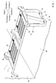
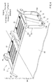
FIG. 1 is a perspective view of a vehicle seat mounting structure for a right rear seat according to Embodiment 1 of the present invention. -
FIG. 2 is a side view of a main portion ofFIG. 1 . -
FIG. 3 is a sectional view taken along line III-III ofFIG. 2 . -
FIG. 4 is a perspective view of a vehicle seat mounting structure for a right rear seat according toEmbodiment 2 of the present invention. -
FIG. 5 is a side view of a main portion ofFIG. 4 . -
FIG. 6 is a sectional view taken along line VI-VI ofFIG. 5 . -
FIG. 7 is a perspective view of a conventional vehicle seat mounting structure for a right rear seat. -
FIG. 8 is a side view of a main portion ofFIG. 7 . -
FIG. 9 is a sectional view taken along line IX-IX ofFIG. 8 . - In the following, a mode for carrying out the present invention will be described with reference to the drawings. In the following description, "a right rear seat 1" of a van type vehicle will be exemplified as "a vehicle seat." Further, upward and downward, forward and backward, and rightward and leftward in the description respectively correspond to upward and downward, forward and backward, and rightward and leftward in the drawings described above, i.e., upward and downward, forward and backward, and rightward and leftward with respect to the right rear seat 1.
- First, Embodiment 1 of the present invention will be described with reference to
FIGS. 1 to 3 . First, a structure of the right rear seat 1 according to Embodiment 1 will be schematically described with reference toFIG. 1 . The right rear seat 1 is a seat for two people and is composed of aseat cushion 2 and a seatback (not shown). Of theseat cushion 2 and the seatback, theseat cushion 2 will be described in detail. - Further, because the seatback may have a well-known structure, a detailed description thereof may be omitted. Further, in
FIG. 1 , a cushion pad and a seat cover are omitted such that an internal structure of the seat cushion of the right rear seat 1 may be clearly seen. This may apply inEmbodiment 2 described below. - The
seat cushion 2 is composed of acushion frame 10, a well-known cushion pad (not shown) attached to thecushion frame 10 while wrapping around the same, and a well-known seat cover (not shown) that covers a surface of the cushion pad. Thecushion frame 10 is mainly composed of a framemain body 20 and aleg 30. In the following, the framemain body 20 and theleg 30 will be individually described. - First, the frame
main body 20 will be described. The framemain body 20 is a member forming a framework of theseat cushion 2 and is formed as a rectangular frame. The rectangular frame has a plurality ofsprings 22 --- 22 that are positioned therein so as to extend back and forth thereof. Thus, theseat cushion 2 may be comfortable to sit on for an occupant. Further, the framemain body 20 hasbrackets FIG. 1 ) in order to connect the same to a rightinner wall 64 of the vehicle. - Next, the
leg 30 will be described. Theleg 30 is a member for connecting theseat cushion 2 to avehicle floor 60 and is formed so as to have a substantially U-shape. Theleg 30 is formed as a substantially rectangular tube that is constructed of afirst wall 40, asecond wall 42, athird wall 44 and a fourth wall 46 (FIG. 3 ). Of three sides of the substantially U-shapedleg 30, a side having no free end (a bottom side inFIG. 1 which will be hereinafter referred to as "abase side 32") has a pair of front and rear through-holes - That is, the first wall 40 (a lower wall in
FIGS. 1 to 3 ) of thebase side 32 has a pair of front and rear mountingholes holes 40a are configured such thatbushes 50, which will be hereinafter described, can be inserted thereinto. A diameter of each of the mountingholes 40a may be referred to as "D1." - Further, the second wall 42 (an upper wall in
FIGS. 1 to 3 ) of thebase side 32 also has a pair of front and rear mountingholes holes 42a are configured such thatbolts 70, which will be hereinafter described, can be inserted thereinto. A diameter of each of the mountingholes 42a may be referred to as "D2". Further, the mountingholes - Further, the diameters of the mounting
holes FIGS. 2 and3 or a side opposite to a side in which aflange 54 is formed) is inserted into each of the mountingholes 40a of theleg 30 until theflange 54 of each of thebushes 50 can be engaged with a periphery of each of the mountingholes 40a, the other end side of each of thebushes 50 can contact a periphery of each of the mountingholes 42a formed in thesecond wall 42 of theleg 30, which will be hereinafter described. - Each of the
bushes 50 will be described in detail. Each of thebushes 50 is formed as a cylindrical metal member having an insertion bore 52 into which each of thebolts 70 can be inserted. Theflange 54 is formed in a periphery of one axial end of each of the bushes 50 (a lower end inFIGS. 2 and3 ). - An axial length of each of the
bushes 50 is set such that when the other axial end side thereof (the upper end side inFIGS. 2 and3 or the side opposite to the side in which theflange 54 is formed) is inserted into each of the mountingholes 40a of theleg 30 until theflange 54 of each of thebushes 50 can be engaged with the periphery of each of the mountingholes 40a, the other end side can contact an inner surface of thesecond wall 42 of the leg 30 (the periphery of the mountinghole 42a). Thus, even when the insertedbolts 70 and the nuts 72 are tightly fastened after thebolts 70 are inserted into the insertion bores 52 of thebushes 50, theleg 30 can be prevented from being crushed. - Further, the
flange 54 of each of thebushes 50 and thefirst wall 40 of theleg 30 are bonded to each other by welding in a condition in which the other axial end side of each of thebushes 50 is inserted into each of the mountingholes 40a of theleg 30 until theflange 54 of each of thebushes 50 can be engaged with the periphery of each of the mountingholes 40a, i.e., in a condition in which the other end side contacts the inner surface of thesecond wall 42 of the leg 30 (the periphery of each of the mountingholes 42a). InFIGS. 2 and3 , a welding portion is shown by "A." - Both of free ends of the
leg 30 are respectively connected to front and rear ends of the framemain body 20 in an inner side thereof (a right side inFIG. 1 ). The right rear seat 1 is constructed of theseat cushion 2 having thecushion frame 10 that is composed of the framemain body 20 and theleg 30, and a well-known seatback. - Next, procedures for mounting the right rear seat 1 in an interior of a vehicle cabin will be described. First, the right rear seat 1 is positioned in a predetermined position in the interior of the vehicle cabin. The predetermined position means a right rear portion in the interior of the vehicle cabin.
- Next, both of the
brackets main body 20 and the rightinner wall 64 of the vehicle are respectively fastened together via bolts and nuts (both of which are not shown), so that thebrackets inner wall 64 is performed. Further, the term "fastened together" means that the bolt is passed through the bracket 24 (26) and theinner wall 64 and is then fastened by the nut. - Thereafter, similar to the procedure described above, the
leg 30 and thevehicle floor 60 are fastened together via thebolts leg 30 is connected to thevehicle floor 60. That is, thebolts 70 are passed through the mountingholes 40a of theleg 30 and mountingholes 62 formed in thevehicle floor 60 via the mountingholes 42a of theleg 30 and thebolts 70 passed therethrough are then fastened by the nuts 72 from a back side of thevehicle floor 60. - When a fastening operation is thus performed, the
second wall 42 of theleg 30 is interleaved between a head portion of each of thebolts 70 and the other axial end side of each of thebushes 50. Further, when such a fastening operation is performed, theflange 54 of each of thebushes 50 are interleaved between thefirst wall 40 of theleg 30 and thevehicle floor 60. The fastening operation is performed in each of a pair of front and rear positions of the leg 30 (two positions). In this way, the right rear seat 1 is mounted on the interior of the vehicle cabin. - A vehicle seat mounting structure for the right rear seat 1 according to Embodiment 1 of the present invention is constructed as described above. According to the structure, when the
leg 30 and thevehicle floor 60 are fastened together via thebolts 70 and the nuts 72, a fastening force is exerted on thesecond wall 42 of theleg 30, thebushes 50 and thevehicle floor 60. As a result, as described in connection with a conventional structure, theleg 30 can be prevented from being crushed even if thebolts 70 and the nuts 72 are tightly fastened, so that mounting strength of the right rear seat 1 can be increased. At this time, the other axial end side of each of thebushes 50 contacts the inner surface of thesecond wall 42 of the leg 30 (the periphery of each of the mountingholes 42a). Therefore, in order to secure the each of thebushes 50 to theleg 30, only a single welding portion (a welding portion between one axial end side of each of the bushes and the first wall of the leg, i.e., a portion shown by A inFIGS. 2 and3 ) is necessary. Thus, unlike the conventional structure, the welding portion can be prevented from being exposed. As a result, an appearance of each of mounting portions of the right rear seat 1 can be prevented from being reduced. - Further, in this structure, the
flange 54 of each of thebushes 50 and thefirst wall 40 of theleg 30 are bonded to each other by welding. Therefore, the right rear seat 1 can be mounted on thevehicle floor 60 while thebushes 50 are secured to theleg 30. Thus, as compared with a case in which such securing is not effected, workability of mounting can be increased. - Next,
Embodiment 2 of the present invention will be described with reference toFIGS. 4 to 6 . Unlike the right rear seat 1 according to Embodiment 1 previously described, in a rightrear seat 201 according toEmbodiment 2, the substantiallyU-shaped leg 30 is reinforced in bent portions thereof. Further, the rightrear seat 201 according toEmbodiment 2 is the same as the right rear seat 1 according to Embodiment 1 except for a reinforcement structure. Therefore, the same elements will be identified by the same reference numerals in the drawings and a detailed description of such elements will be omitted. - As shown in
FIGS. 4 to 6 , reinforcingcovers second wall 42 of the substantiallyU-shaped leg 30 of the rightrear seat 201 in the bent portions by welding. InFIGS. 5 and6 , each of welding portions is shown by "C." - A vehicle seat mounting structure for the right
rear seat 201 according toEmbodiment 2 of the present invention is constructed as described above. Such a structure may have the same effects as the vehicle seat mounting structure for the right rear seat 1 according to Embodiment 1. Further, in the structure, because the reinforcingcovers leg 30 can be strengthened. - The above description simply relates to embodiments of the present invention. That is, the present invention is not limited to the embodiments described above.
In the embodiments, "the right rear seat 1" of the van type vehicle is exemplified as "the vehicle seat." However, the vehicle seat may be "a left rear seat." In such a case, positions of thebrackets leg 30 may be reversed right and left.
Claims (2)
- A vehicle seat mounting structure in which a leg is secured to a seat cushion and is formed as a substantially rectangular tube by four walls of a first wall, a second wall, a third wall and a fourth wall, in which the first wall facing a vehicle floor and the second wall facing the first wall are fastened together to the vehicle floor via a bolt and a nut, and in which a substantially tubular metal bush capable of preventing the leg from being crushed by the fastening-together action is positioned in the leg in a manner such that the bolt can be inserted thereinto,
wherein the bush has a flange that is formed in a periphery of one axial end thereof,
wherein the flange is interleaved between the first wall of the leg and the vehicle floor, and
wherein the second wall of the leg is interleaved between a head portion of the bolt and the other axial end of the bush. - The vehicle seat mounting structure as defined in claim 1, wherein the flange of the bush and the first wall of the leg are bonded to each other by welding.
Applications Claiming Priority (2)
| Application Number | Priority Date | Filing Date | Title |
|---|---|---|---|
| JP2010141466 | 2010-06-22 | ||
| PCT/JP2011/059699 WO2011162017A1 (en) | 2010-06-22 | 2011-04-20 | Vehicle seat mounting structure |
Publications (3)
| Publication Number | Publication Date |
|---|---|
| EP2586653A1 true EP2586653A1 (en) | 2013-05-01 |
| EP2586653A4 EP2586653A4 (en) | 2013-10-30 |
| EP2586653B1 EP2586653B1 (en) | 2014-10-22 |
Family
ID=45371220
Family Applications (1)
| Application Number | Title | Priority Date | Filing Date |
|---|---|---|---|
| EP11797905.4A Not-in-force EP2586653B1 (en) | 2010-06-22 | 2011-04-20 | Vehicle seat mounting structure |
Country Status (5)
| Country | Link |
|---|---|
| EP (1) | EP2586653B1 (en) |
| JP (1) | JP5490896B2 (en) |
| CN (1) | CN103025576B (en) |
| AU (1) | AU2011270523B2 (en) |
| WO (1) | WO2011162017A1 (en) |
Cited By (1)
| Publication number | Priority date | Publication date | Assignee | Title |
|---|---|---|---|---|
| PL126744U1 (en) * | 2017-10-30 | 2019-05-06 | Brodawka Marek Przed Produkcyjno Handlowo Uslugowe Mkm Spolka Cywilna | Automobile chair base |
Families Citing this family (4)
| Publication number | Priority date | Publication date | Assignee | Title |
|---|---|---|---|---|
| DE102012108119A1 (en) * | 2012-08-31 | 2014-03-06 | Recaro Aircraft Seating Gmbh & Co. Kg | Seat dividers device |
| DE102013008299A1 (en) * | 2013-05-15 | 2014-11-20 | Man Truck & Bus Ag | Holding device, in particular for a vehicle seat |
| JP6558225B2 (en) * | 2015-11-20 | 2019-08-14 | トヨタ紡織株式会社 | Vehicle seat frame |
| CN108790986A (en) * | 2017-05-04 | 2018-11-13 | 江苏卡威汽车工业集团股份有限公司 | A kind of two people's seat of honour cushion reinforcing plates |
Family Cites Families (8)
| Publication number | Priority date | Publication date | Assignee | Title |
|---|---|---|---|---|
| JPS58171729U (en) * | 1982-05-14 | 1983-11-16 | 荒川車体工業株式会社 | Seat leg structure for buses |
| JP3132158B2 (en) * | 1992-06-30 | 2001-02-05 | スズキ株式会社 | Car seat with child seat |
| JP4482482B2 (en) | 2005-05-12 | 2010-06-16 | 本田技研工業株式会社 | Support structure for vehicle seat |
| EP1930209B1 (en) * | 2005-09-30 | 2010-06-02 | TS Tech Co., Ltd | Occupant weight measurement device for vehicle seat and installation structure for load sensor |
| JP5055918B2 (en) * | 2006-09-28 | 2012-10-24 | アイシン精機株式会社 | Power seat slide device |
| US7729122B2 (en) * | 2006-10-13 | 2010-06-01 | Illinois Tool Works Inc. | Fastener for heat sinks |
| DE102006060829B4 (en) * | 2006-12-22 | 2010-03-25 | Keiper Gmbh & Co. Kg | Bearing arrangement, in particular a vehicle seat |
| JP5225603B2 (en) * | 2007-03-30 | 2013-07-03 | 株式会社ブリヂストン | Vibration isolator |
-
2011
- 2011-04-20 JP JP2012521361A patent/JP5490896B2/en active Active
- 2011-04-20 EP EP11797905.4A patent/EP2586653B1/en not_active Not-in-force
- 2011-04-20 AU AU2011270523A patent/AU2011270523B2/en not_active Ceased
- 2011-04-20 WO PCT/JP2011/059699 patent/WO2011162017A1/en not_active Ceased
- 2011-04-20 CN CN201180031096.2A patent/CN103025576B/en not_active Expired - Fee Related
Cited By (1)
| Publication number | Priority date | Publication date | Assignee | Title |
|---|---|---|---|---|
| PL126744U1 (en) * | 2017-10-30 | 2019-05-06 | Brodawka Marek Przed Produkcyjno Handlowo Uslugowe Mkm Spolka Cywilna | Automobile chair base |
Also Published As
| Publication number | Publication date |
|---|---|
| EP2586653B1 (en) | 2014-10-22 |
| AU2011270523A1 (en) | 2013-01-10 |
| AU2011270523B2 (en) | 2014-03-20 |
| WO2011162017A1 (en) | 2011-12-29 |
| EP2586653A4 (en) | 2013-10-30 |
| JPWO2011162017A1 (en) | 2013-08-19 |
| CN103025576A (en) | 2013-04-03 |
| JP5490896B2 (en) | 2014-05-14 |
| CN103025576B (en) | 2015-04-29 |
Similar Documents
| Publication | Publication Date | Title |
|---|---|---|
| US8931850B2 (en) | Seat back frame | |
| EP2586653B1 (en) | Vehicle seat mounting structure | |
| JP4189804B2 (en) | Seat back hinge structure | |
| US8833857B2 (en) | Vehicle seat | |
| JPH10203293A (en) | Device for supporting air bag module in vehicle | |
| CN109955920B (en) | body rear structure | |
| EP1829736B1 (en) | Automobile seat | |
| EP3575143B1 (en) | Vehicular seat structure | |
| JP5906707B2 (en) | Seat frame structure for vehicle seat | |
| JP5297054B2 (en) | Vehicle seat | |
| JP2018090144A (en) | Vehicular seat | |
| JP2018199362A (en) | Vehicle seat | |
| JP5005781B2 (en) | Vehicle seat | |
| JP2000344160A (en) | Fitting structure for vehicle component | |
| JP2007269100A (en) | Headrest structure | |
| JP7215653B2 (en) | VEHICLE SEAT AND METHOD FOR MANUFACTURING VEHICLE SEAT | |
| US11318873B2 (en) | Headrest support structure and vehicle seat | |
| JP2000106972A (en) | Backrest mounting support structure for vehicle seats | |
| JP2025173901A (en) | Vehicle seats | |
| JP6620663B2 (en) | Vehicle seat and manufacturing method thereof | |
| JP2003219931A (en) | Bus seat frame structure | |
| JP6697213B2 (en) | Seat structure | |
| JP2003220870A (en) | Bus seat frame structure | |
| CN119218073A (en) | Cushion frame for vehicle seat | |
| JP2026002527A (en) | Vehicle front structure |
Legal Events
| Date | Code | Title | Description |
|---|---|---|---|
| PUAI | Public reference made under article 153(3) epc to a published international application that has entered the european phase |
Free format text: ORIGINAL CODE: 0009012 |
|
| 17P | Request for examination filed |
Effective date: 20121228 |
|
| AK | Designated contracting states |
Kind code of ref document: A1 Designated state(s): AL AT BE BG CH CY CZ DE DK EE ES FI FR GB GR HR HU IE IS IT LI LT LU LV MC MK MT NL NO PL PT RO RS SE SI SK SM TR |
|
| DAX | Request for extension of the european patent (deleted) | ||
| A4 | Supplementary search report drawn up and despatched |
Effective date: 20130927 |
|
| RIC1 | Information provided on ipc code assigned before grant |
Ipc: B60N 2/00 20060101ALI20130923BHEP Ipc: B60N 2/015 20060101ALI20130923BHEP Ipc: B60N 2/50 20060101AFI20130923BHEP Ipc: B60N 2/68 20060101ALI20130923BHEP |
|
| GRAP | Despatch of communication of intention to grant a patent |
Free format text: ORIGINAL CODE: EPIDOSNIGR1 |
|
| INTG | Intention to grant announced |
Effective date: 20140523 |
|
| GRAS | Grant fee paid |
Free format text: ORIGINAL CODE: EPIDOSNIGR3 |
|
| GRAA | (expected) grant |
Free format text: ORIGINAL CODE: 0009210 |
|
| AK | Designated contracting states |
Kind code of ref document: B1 Designated state(s): AL AT BE BG CH CY CZ DE DK EE ES FI FR GB GR HR HU IE IS IT LI LT LU LV MC MK MT NL NO PL PT RO RS SE SI SK SM TR |
|
| REG | Reference to a national code |
Ref country code: GB Ref legal event code: FG4D |
|
| REG | Reference to a national code |
Ref country code: CH Ref legal event code: EP |
|
| REG | Reference to a national code |
Ref country code: AT Ref legal event code: REF Ref document number: 692458 Country of ref document: AT Kind code of ref document: T Effective date: 20141115 |
|
| REG | Reference to a national code |
Ref country code: IE Ref legal event code: FG4D |
|
| REG | Reference to a national code |
Ref country code: DE Ref legal event code: R096 Ref document number: 602011010842 Country of ref document: DE Effective date: 20141204 |
|
| REG | Reference to a national code |
Ref country code: NL Ref legal event code: VDEP Effective date: 20141022 |
|
| REG | Reference to a national code |
Ref country code: AT Ref legal event code: MK05 Ref document number: 692458 Country of ref document: AT Kind code of ref document: T Effective date: 20141022 |
|
| REG | Reference to a national code |
Ref country code: LT Ref legal event code: MG4D |
|
| REG | Reference to a national code |
Ref country code: FR Ref legal event code: PLFP Year of fee payment: 5 |
|
| PG25 | Lapsed in a contracting state [announced via postgrant information from national office to epo] |
Ref country code: LT Free format text: LAPSE BECAUSE OF FAILURE TO SUBMIT A TRANSLATION OF THE DESCRIPTION OR TO PAY THE FEE WITHIN THE PRESCRIBED TIME-LIMIT Effective date: 20141022 Ref country code: NO Free format text: LAPSE BECAUSE OF FAILURE TO SUBMIT A TRANSLATION OF THE DESCRIPTION OR TO PAY THE FEE WITHIN THE PRESCRIBED TIME-LIMIT Effective date: 20150122 Ref country code: PT Free format text: LAPSE BECAUSE OF FAILURE TO SUBMIT A TRANSLATION OF THE DESCRIPTION OR TO PAY THE FEE WITHIN THE PRESCRIBED TIME-LIMIT Effective date: 20150223 Ref country code: NL Free format text: LAPSE BECAUSE OF FAILURE TO SUBMIT A TRANSLATION OF THE DESCRIPTION OR TO PAY THE FEE WITHIN THE PRESCRIBED TIME-LIMIT Effective date: 20141022 Ref country code: ES Free format text: LAPSE BECAUSE OF FAILURE TO SUBMIT A TRANSLATION OF THE DESCRIPTION OR TO PAY THE FEE WITHIN THE PRESCRIBED TIME-LIMIT Effective date: 20141022 Ref country code: FI Free format text: LAPSE BECAUSE OF FAILURE TO SUBMIT A TRANSLATION OF THE DESCRIPTION OR TO PAY THE FEE WITHIN THE PRESCRIBED TIME-LIMIT Effective date: 20141022 Ref country code: IS Free format text: LAPSE BECAUSE OF FAILURE TO SUBMIT A TRANSLATION OF THE DESCRIPTION OR TO PAY THE FEE WITHIN THE PRESCRIBED TIME-LIMIT Effective date: 20150222 |
|
| PG25 | Lapsed in a contracting state [announced via postgrant information from national office to epo] |
Ref country code: HR Free format text: LAPSE BECAUSE OF FAILURE TO SUBMIT A TRANSLATION OF THE DESCRIPTION OR TO PAY THE FEE WITHIN THE PRESCRIBED TIME-LIMIT Effective date: 20141022 Ref country code: PL Free format text: LAPSE BECAUSE OF FAILURE TO SUBMIT A TRANSLATION OF THE DESCRIPTION OR TO PAY THE FEE WITHIN THE PRESCRIBED TIME-LIMIT Effective date: 20141022 Ref country code: CY Free format text: LAPSE BECAUSE OF FAILURE TO SUBMIT A TRANSLATION OF THE DESCRIPTION OR TO PAY THE FEE WITHIN THE PRESCRIBED TIME-LIMIT Effective date: 20141022 Ref country code: RS Free format text: LAPSE BECAUSE OF FAILURE TO SUBMIT A TRANSLATION OF THE DESCRIPTION OR TO PAY THE FEE WITHIN THE PRESCRIBED TIME-LIMIT Effective date: 20141022 Ref country code: SE Free format text: LAPSE BECAUSE OF FAILURE TO SUBMIT A TRANSLATION OF THE DESCRIPTION OR TO PAY THE FEE WITHIN THE PRESCRIBED TIME-LIMIT Effective date: 20141022 Ref country code: AT Free format text: LAPSE BECAUSE OF FAILURE TO SUBMIT A TRANSLATION OF THE DESCRIPTION OR TO PAY THE FEE WITHIN THE PRESCRIBED TIME-LIMIT Effective date: 20141022 Ref country code: LV Free format text: LAPSE BECAUSE OF FAILURE TO SUBMIT A TRANSLATION OF THE DESCRIPTION OR TO PAY THE FEE WITHIN THE PRESCRIBED TIME-LIMIT Effective date: 20141022 Ref country code: GR Free format text: LAPSE BECAUSE OF FAILURE TO SUBMIT A TRANSLATION OF THE DESCRIPTION OR TO PAY THE FEE WITHIN THE PRESCRIBED TIME-LIMIT Effective date: 20150123 |
|
| REG | Reference to a national code |
Ref country code: DE Ref legal event code: R097 Ref document number: 602011010842 Country of ref document: DE |
|
| PG25 | Lapsed in a contracting state [announced via postgrant information from national office to epo] |
Ref country code: CZ Free format text: LAPSE BECAUSE OF FAILURE TO SUBMIT A TRANSLATION OF THE DESCRIPTION OR TO PAY THE FEE WITHIN THE PRESCRIBED TIME-LIMIT Effective date: 20141022 Ref country code: SK Free format text: LAPSE BECAUSE OF FAILURE TO SUBMIT A TRANSLATION OF THE DESCRIPTION OR TO PAY THE FEE WITHIN THE PRESCRIBED TIME-LIMIT Effective date: 20141022 Ref country code: RO Free format text: LAPSE BECAUSE OF FAILURE TO SUBMIT A TRANSLATION OF THE DESCRIPTION OR TO PAY THE FEE WITHIN THE PRESCRIBED TIME-LIMIT Effective date: 20141022 Ref country code: DK Free format text: LAPSE BECAUSE OF FAILURE TO SUBMIT A TRANSLATION OF THE DESCRIPTION OR TO PAY THE FEE WITHIN THE PRESCRIBED TIME-LIMIT Effective date: 20141022 Ref country code: EE Free format text: LAPSE BECAUSE OF FAILURE TO SUBMIT A TRANSLATION OF THE DESCRIPTION OR TO PAY THE FEE WITHIN THE PRESCRIBED TIME-LIMIT Effective date: 20141022 |
|
| PLBE | No opposition filed within time limit |
Free format text: ORIGINAL CODE: 0009261 |
|
| STAA | Information on the status of an ep patent application or granted ep patent |
Free format text: STATUS: NO OPPOSITION FILED WITHIN TIME LIMIT |
|
| PG25 | Lapsed in a contracting state [announced via postgrant information from national office to epo] |
Ref country code: IT Free format text: LAPSE BECAUSE OF FAILURE TO SUBMIT A TRANSLATION OF THE DESCRIPTION OR TO PAY THE FEE WITHIN THE PRESCRIBED TIME-LIMIT Effective date: 20141022 |
|
| 26N | No opposition filed |
Effective date: 20150723 |
|
| PG25 | Lapsed in a contracting state [announced via postgrant information from national office to epo] |
Ref country code: MC Free format text: LAPSE BECAUSE OF FAILURE TO SUBMIT A TRANSLATION OF THE DESCRIPTION OR TO PAY THE FEE WITHIN THE PRESCRIBED TIME-LIMIT Effective date: 20141022 Ref country code: LU Free format text: LAPSE BECAUSE OF FAILURE TO SUBMIT A TRANSLATION OF THE DESCRIPTION OR TO PAY THE FEE WITHIN THE PRESCRIBED TIME-LIMIT Effective date: 20150420 |
|
| REG | Reference to a national code |
Ref country code: CH Ref legal event code: PL |
|
| REG | Reference to a national code |
Ref country code: IE Ref legal event code: MM4A |
|
| PG25 | Lapsed in a contracting state [announced via postgrant information from national office to epo] |
Ref country code: CH Free format text: LAPSE BECAUSE OF NON-PAYMENT OF DUE FEES Effective date: 20150430 Ref country code: LI Free format text: LAPSE BECAUSE OF NON-PAYMENT OF DUE FEES Effective date: 20150430 |
|
| PG25 | Lapsed in a contracting state [announced via postgrant information from national office to epo] |
Ref country code: SI Free format text: LAPSE BECAUSE OF FAILURE TO SUBMIT A TRANSLATION OF THE DESCRIPTION OR TO PAY THE FEE WITHIN THE PRESCRIBED TIME-LIMIT Effective date: 20141022 |
|
| REG | Reference to a national code |
Ref country code: FR Ref legal event code: PLFP Year of fee payment: 6 |
|
| PG25 | Lapsed in a contracting state [announced via postgrant information from national office to epo] |
Ref country code: IE Free format text: LAPSE BECAUSE OF NON-PAYMENT OF DUE FEES Effective date: 20150420 |
|
| PG25 | Lapsed in a contracting state [announced via postgrant information from national office to epo] |
Ref country code: MT Free format text: LAPSE BECAUSE OF FAILURE TO SUBMIT A TRANSLATION OF THE DESCRIPTION OR TO PAY THE FEE WITHIN THE PRESCRIBED TIME-LIMIT Effective date: 20141022 |
|
| REG | Reference to a national code |
Ref country code: FR Ref legal event code: PLFP Year of fee payment: 7 |
|
| PG25 | Lapsed in a contracting state [announced via postgrant information from national office to epo] |
Ref country code: BG Free format text: LAPSE BECAUSE OF FAILURE TO SUBMIT A TRANSLATION OF THE DESCRIPTION OR TO PAY THE FEE WITHIN THE PRESCRIBED TIME-LIMIT Effective date: 20141022 Ref country code: SM Free format text: LAPSE BECAUSE OF FAILURE TO SUBMIT A TRANSLATION OF THE DESCRIPTION OR TO PAY THE FEE WITHIN THE PRESCRIBED TIME-LIMIT Effective date: 20141022 Ref country code: HU Free format text: LAPSE BECAUSE OF FAILURE TO SUBMIT A TRANSLATION OF THE DESCRIPTION OR TO PAY THE FEE WITHIN THE PRESCRIBED TIME-LIMIT; INVALID AB INITIO Effective date: 20110420 |
|
| PG25 | Lapsed in a contracting state [announced via postgrant information from national office to epo] |
Ref country code: TR Free format text: LAPSE BECAUSE OF FAILURE TO SUBMIT A TRANSLATION OF THE DESCRIPTION OR TO PAY THE FEE WITHIN THE PRESCRIBED TIME-LIMIT Effective date: 20141022 |
|
| PG25 | Lapsed in a contracting state [announced via postgrant information from national office to epo] |
Ref country code: BE Free format text: LAPSE BECAUSE OF FAILURE TO SUBMIT A TRANSLATION OF THE DESCRIPTION OR TO PAY THE FEE WITHIN THE PRESCRIBED TIME-LIMIT Effective date: 20141022 |
|
| REG | Reference to a national code |
Ref country code: FR Ref legal event code: PLFP Year of fee payment: 8 |
|
| PG25 | Lapsed in a contracting state [announced via postgrant information from national office to epo] |
Ref country code: MK Free format text: LAPSE BECAUSE OF FAILURE TO SUBMIT A TRANSLATION OF THE DESCRIPTION OR TO PAY THE FEE WITHIN THE PRESCRIBED TIME-LIMIT Effective date: 20141022 |
|
| PG25 | Lapsed in a contracting state [announced via postgrant information from national office to epo] |
Ref country code: AL Free format text: LAPSE BECAUSE OF FAILURE TO SUBMIT A TRANSLATION OF THE DESCRIPTION OR TO PAY THE FEE WITHIN THE PRESCRIBED TIME-LIMIT Effective date: 20141022 |
|
| PGFP | Annual fee paid to national office [announced via postgrant information from national office to epo] |
Ref country code: FR Payment date: 20190313 Year of fee payment: 9 |
|
| PGFP | Annual fee paid to national office [announced via postgrant information from national office to epo] |
Ref country code: DE Payment date: 20190410 Year of fee payment: 9 |
|
| PGFP | Annual fee paid to national office [announced via postgrant information from national office to epo] |
Ref country code: GB Payment date: 20190417 Year of fee payment: 9 |
|
| REG | Reference to a national code |
Ref country code: DE Ref legal event code: R119 Ref document number: 602011010842 Country of ref document: DE |
|
| PG25 | Lapsed in a contracting state [announced via postgrant information from national office to epo] |
Ref country code: DE Free format text: LAPSE BECAUSE OF NON-PAYMENT OF DUE FEES Effective date: 20201103 Ref country code: FR Free format text: LAPSE BECAUSE OF NON-PAYMENT OF DUE FEES Effective date: 20200430 |
|
| GBPC | Gb: european patent ceased through non-payment of renewal fee |
Effective date: 20200420 |
|
| PG25 | Lapsed in a contracting state [announced via postgrant information from national office to epo] |
Ref country code: GB Free format text: LAPSE BECAUSE OF NON-PAYMENT OF DUE FEES Effective date: 20200420 |