EP2586192B1 - Erkennung von signalverschlechterung - Google Patents
Erkennung von signalverschlechterung Download PDFInfo
- Publication number
- EP2586192B1 EP2586192B1 EP11724083.8A EP11724083A EP2586192B1 EP 2586192 B1 EP2586192 B1 EP 2586192B1 EP 11724083 A EP11724083 A EP 11724083A EP 2586192 B1 EP2586192 B1 EP 2586192B1
- Authority
- EP
- European Patent Office
- Prior art keywords
- receiver
- test
- merit
- error
- time instance
- Prior art date
- Legal status (The legal status is an assumption and is not a legal conclusion. Google has not performed a legal analysis and makes no representation as to the accuracy of the status listed.)
- Active
Links
Images
Classifications
-
- H—ELECTRICITY
- H04—ELECTRIC COMMUNICATION TECHNIQUE
- H04B—TRANSMISSION
- H04B17/00—Monitoring; Testing
- H04B17/30—Monitoring; Testing of propagation channels
- H04B17/373—Predicting channel quality or other radio frequency [RF] parameters
-
- H—ELECTRICITY
- H04—ELECTRIC COMMUNICATION TECHNIQUE
- H04L—TRANSMISSION OF DIGITAL INFORMATION, e.g. TELEGRAPHIC COMMUNICATION
- H04L41/00—Arrangements for maintenance, administration or management of data switching networks, e.g. of packet switching networks
- H04L41/14—Network analysis or design
- H04L41/147—Network analysis or design for predicting network behaviour
-
- H—ELECTRICITY
- H04—ELECTRIC COMMUNICATION TECHNIQUE
- H04L—TRANSMISSION OF DIGITAL INFORMATION, e.g. TELEGRAPHIC COMMUNICATION
- H04L41/00—Arrangements for maintenance, administration or management of data switching networks, e.g. of packet switching networks
- H04L41/14—Network analysis or design
- H04L41/149—Network analysis or design for prediction of maintenance
-
- H—ELECTRICITY
- H04—ELECTRIC COMMUNICATION TECHNIQUE
- H04N—PICTORIAL COMMUNICATION, e.g. TELEVISION
- H04N17/00—Diagnosis, testing or measuring for television systems or their details
- H04N17/004—Diagnosis, testing or measuring for television systems or their details for digital television systems
-
- H—ELECTRICITY
- H04—ELECTRIC COMMUNICATION TECHNIQUE
- H04N—PICTORIAL COMMUNICATION, e.g. TELEVISION
- H04N21/00—Selective content distribution, e.g. interactive television or video on demand [VOD]
- H04N21/20—Servers specifically adapted for the distribution of content, e.g. VOD servers; Operations thereof
- H04N21/25—Management operations performed by the server for facilitating the content distribution or administrating data related to end-users or client devices, e.g. end-user or client device authentication, learning user preferences for recommending movies
- H04N21/258—Client or end-user data management, e.g. managing client capabilities, user preferences or demographics, processing of multiple end-users preferences to derive collaborative data
- H04N21/25808—Management of client data
-
- H—ELECTRICITY
- H04—ELECTRIC COMMUNICATION TECHNIQUE
- H04N—PICTORIAL COMMUNICATION, e.g. TELEVISION
- H04N21/00—Selective content distribution, e.g. interactive television or video on demand [VOD]
- H04N21/40—Client devices specifically adapted for the reception of or interaction with content, e.g. set-top-box [STB]; Operations thereof
- H04N21/43—Processing of content or additional data, e.g. demultiplexing additional data from a digital video stream; Elementary client operations, e.g. monitoring of home network or synchronising decoder's clock; Client middleware
- H04N21/442—Monitoring of processes or resources, e.g. detecting the failure of a recording device, monitoring the downstream bandwidth, the number of times a movie has been viewed, the storage space available from the internal hard disk
- H04N21/44209—Monitoring of downstream path of the transmission network originating from a server, e.g. bandwidth variations of a wireless network
-
- H—ELECTRICITY
- H04—ELECTRIC COMMUNICATION TECHNIQUE
- H04N—PICTORIAL COMMUNICATION, e.g. TELEVISION
- H04N21/00—Selective content distribution, e.g. interactive television or video on demand [VOD]
- H04N21/60—Network structure or processes for video distribution between server and client or between remote clients; Control signalling between clients, server and network components; Transmission of management data between server and client, e.g. sending from server to client commands for recording incoming content stream; Communication details between server and client
- H04N21/61—Network physical structure; Signal processing
- H04N21/6106—Network physical structure; Signal processing specially adapted to the downstream path of the transmission network
- H04N21/6118—Network physical structure; Signal processing specially adapted to the downstream path of the transmission network involving cable transmission, e.g. using a cable modem
-
- H—ELECTRICITY
- H04—ELECTRIC COMMUNICATION TECHNIQUE
- H04N—PICTORIAL COMMUNICATION, e.g. TELEVISION
- H04N21/00—Selective content distribution, e.g. interactive television or video on demand [VOD]
- H04N21/60—Network structure or processes for video distribution between server and client or between remote clients; Control signalling between clients, server and network components; Transmission of management data between server and client, e.g. sending from server to client commands for recording incoming content stream; Communication details between server and client
- H04N21/65—Transmission of management data between client and server
- H04N21/658—Transmission by the client directed to the server
- H04N21/6582—Data stored in the client, e.g. viewing habits, hardware capabilities, credit card number
-
- H—ELECTRICITY
- H04—ELECTRIC COMMUNICATION TECHNIQUE
- H04L—TRANSMISSION OF DIGITAL INFORMATION, e.g. TELEGRAPHIC COMMUNICATION
- H04L43/00—Arrangements for monitoring or testing data switching networks
- H04L43/16—Threshold monitoring
Definitions
- the present invention relates to method and to a system for providing maintenance to a receiver or group of receivers.
- Implementations discussed herein are generally directed to predicting, at a service provider, future signal degradation at receivers used to display a programming service.
- signal degradation can be a significant barrier to customer satisfaction in industries that provide service to customers across an electronic transmission medium.
- customers receive program service through a satellite or terrestrial broadcast or across a cable network.
- Customer-side equipment or components that are used to receive signals or display content sent by a service provider may degrade or fail over time, leading to a loss in signal.
- signal degradation may occur in other contexts such as the transmission of information across the Internet or other computer-accessible medium (including a local area network, wide-area network, and so on), including Internet protocol television transmissions, a wireless network such as a radio frequency or infrared network, and so on.
- US6445907B1 discloses an example of a method and system for reporting satellite receiver diagnostic information to a remote location.
- a method for providing maintenance to a receiver comprising: determining a time series of test quantities for a receiver, the test quantities based on signal strength measurements collected at the receiver at plurality of time instances; and, receiving a figure of merit for the receiver, the figure of merit indicating an expected signal quality for the receiver, the method being characterised by applying linear regression to the time series of test quantities and the figure of merit to produce a linear function; determining a failure prediction for the receiver based on the linear function; and identifying the receiver for maintenance if the failure prediction indicates a future unacceptable signal strength for the receiver.
- a method for providing maintenance to a plurality of receivers comprising: receiving signal histories for a first group of receivers; identifying a second group of receivers from the first group of receivers, the second group of receivers having a downward trending signal strength and a signal strength below a predetermined level for at least one time instance; processing each receiver of the second group of receivers according to the method described above; creating a linear signal strength function for each of the second group of receivers, the linear signal strength function based on the signal history for the receiver and the predetermined level; identifying a third group of receivers by selecting, from the second group of receivers, those receivers whose linear function has a slope and an intercept that indicate a future unacceptable signal strength identified for maintenance if the failure prediction indicates the future unacceptable signal strength for the respective receiver; and flagging the third group of receivers for maintenance.
- a system for providing maintenance to a receiver comprising: a test quantity module operable to determine a time series of test quantities for a receiver based on signal strength measurements collected at the receiver at plurality of time instances; a figure of merit module operable to receive a figure of merit for the receiver, the figure of merit indicating an expected signal quality for the receiver; and a prediction module operable to determine a failure prediction for the receiver having an unacceptable poor signal strength in the future based on a linear regression function computed from the time series of test quantities and the figure of merit.
- Implementations discussed herein are directed to predicting signal degradation at receivers used to display a programming service.
- the receivers capture signal strength data that is then transmitted to a processing location, which may be associated with a provider of the programming service.
- a signal degradation detector at the provider operates to predict whether or not a future unacceptable signal quality will occur within a time interval.
- a maintenance call may be initiated for those receivers that have such a poor signal quality.
- the prediction may be based on a test quantity calculated from signals captured at the receiver and based on a figure of merit for the geographic locale in which the receiver is located.
- the prediction may be a two part process in which, at a first level, a receiver may be excluded from a maintenance call if the test quantities and the figure of merit indicate an acceptable signal quality.
- a receiver may qualify for a maintenance call if a linear equation calculated for the receiver indicates a future unacceptable signal quality within the time interval.
- Implementations discussed herein are directed to predicting signal degradation at receivers used to display a programming service.
- the receivers capture signal strength data that is then transmitted to a processing location, which may be associated with a provider of the programming service.
- a signal degradation detector at the provider operates to predict whether or not a future unacceptable signal quality will occur within a time interval.
- a maintenance call may be initiated for those receivers that have such a poor signal quality.
- the prediction may be based on a test quantity calculated from signals captured at the receiver and based on a figure of merit for the geographic locale in which the receiver is located.
- the prediction may be a two part process in which, at a first level, a receiver may be excluded from a maintenance call if the test quantities and the figure of merit indicate an acceptable signal quality.
- a receiver may qualify for a maintenance call if a linear equation calculated for the receiver indicates a future unacceptable signal quality within the time interval.
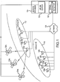
- Fig. 1 is a schematic illustration of a general operating environment showing components and features of embodiments discussed herein.
- Fig. 1 includes a service provider 104 that transmits or otherwise provides a program service transmission to a number of users or subscribers.
- the program service transmission may be received through a subscription to the service.
- the terms "user” and/or “subscriber” refer to an individual or company who receives a program service transmission. This may include those who have purchased a subscription to the program service transmission.
- the terms “user” and/or “subscriber” may refer to individuals who have been given access to the program service transmission through promotional offers and/or other non-fee-based agreements.
- the subscribers to the program service are represented in Fig. 1 as a number of households 108a-n.
- the households 108a-n that receive the program service may be located in a number of different geographic locations.
- the operating environment shown in Fig. 1 includes a first geographic locale 112 and a second geographic locale 116. Households 108a-d are located within the first geographic locale 112, and households 108e-n are located within the second geographic local 116.
- the service provider 104 may be a satellite television provider and so provide a program service transmission through an uplink center 120.
- Implementations discussed herein may utilize a direct broadcast satellite (DBS) system which can incorporate packetized transmission signals according to an appropriate standard, such as the MPEG-2 standard.
- the uplink center 120 may include a transmitter or other equipment operable to transmit a modulated signal having data representing audio and/or visual content.
- the modulated signal may be received at one or more satellites 124a-c, which in turn retransmit the modulated signal to be received at one or more terrestrial locations 108a-n.
- the modulated signal may be transmitted from the satellites 124a-c over an appropriate frequency band such as, for example, the C-band, the Ku-band or the Kaband.
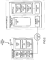
- the modulated signal may be received at the one or more terrestrial locations or households 108a-n through the operation of a receiver 204, shown in detail in Fig. 2 .
- a "receiver" may be any device capable of receiving video and/or audio content included in a broadcast or other program service transmission from a service provider.
- a receiver may include a set-top, a cable box, general purpose computer, and so on.
- a service provider may include any service that provides a program service transmission to a receiver such as, without limitation, a satellite television service, a direct television service or a cable television service.
- program service transmission generally embraces not only satellite or terrestrial broadcasts and/or narrowcasts but also transmission of information across any wired or wireless transmission medium. Accordingly, a “program service transmission” encompasses transmission of information across a cable network (for example a cable headend to cable receiver), an Internet or other computer-accessible medium (including a local area network, wide-area network, and so on), including Internet protocol television transmissions, a wireless network such as a radio frequency or infrared network, and so on.
- a cable network for example a cable headend to cable receiver
- an Internet or other computer-accessible medium including a local area network, wide-area network, and so on
- Internet protocol television transmissions including a wireless network such as a radio frequency or infrared network, and so on.
- Direct broadcast satellite DBS signals may be received as downlinked signals by a satellite antenna 208.
- the downlinked, L-band signals may be received by a tuner 212, which selects a specific frequency range.
- the L-band signals received by the tuner 212 may include a number of transponder signals received from one or more satellites 124a-c.
- a particular transponder signal may include a combination or multiplex of a number of transport streams associated with one or more channels.
- a particular transport stream may include, for example, compressed or uncompressed audio or visual data.
- the tuner 212 may select a particular transponder signal from the group of signals received from the LNBF.
- the transponder signal selected by the tuner 212 may then be demodulated by the demodulator 216. Specifically, the demodulator 216 removes the sinusoidal carrier signal and outputs the information carrying signal as a baseband signal. Output from the demodulator 216 may be directed to a demultiplexer/decoder 220.
- the demultiplexer/decoder 220 may be an integrated circuit that accepts the packetized, time domain multiplexed data stream of the MPEG-2 transport stream and routes the packets to various components for further processing. In so doing, the demultiplexer/decoder 220 may separate out various transport streams that are contained in a particular transponder signal.
- a transport stream may include a number of packets having a unique packet identification (PID).
- PID packet identification
- the demultiplexer/decoder 220 may also unscramble encrypted data and/or provide buffering of the MPEG data.
- a number of transport streams may together form a service.
- a "service” refers to a particular channel which is selected by a user.
- a particular video channel typically includes three transport streams: a video stream, an audio stream, and a data stream.
- the demultiplexer/decoder 220 may include an audio decompressor portion that is operable to decompress an audio stream, and a video decompressor portion that is operable to decompress a video stream.
- the audio stream and video stream may be fully compliant audio and video program elementary streams as defined by, for example, ISO 13818-2 and ISO 13818-3 of the MPEG-2 standard, respectively.
- Output from the demultiplexer/decoder 220 may be directed to an audio visual (AN) processing module 224.
- AN audio visual
- the A/V processing module 224 may process the video and audio streams using digital-to-analog conversion techniques, or compressed digital to uncompressed digital conversion techniques, to produce one or more output signals.
- the resulting baseband signals may then be sent to an output device through appropriate connections.
- the output device may include a television, a monitor, and/or a speaker system, and so on.
- embodiments may operate with different product transmission services. Accordingly, although a satellite system is provided as an example of a program service transmission system, it should be understood that other networks or broadcasts for transmitting data may be used by alternative embodiments. For example, embodiments may be implemented in connection with a cable service. In this case, the service provider 104 and the receiver may communicate over a communication path that includes various combinations of local and wide area networks and/or the Internet. In such embodiments, the receiver may be configured to access a web site, a file transfer protocol (FTP) site, a file sharing system or site, and so on.
- FTP file transfer protocol
- the receiver 204 may include a signal strength detector 228 that is operable to measure signal quality at the receiver 204.
- the measured signal quality is not dependent on the hardware used to convey the program service transmission or to produce the programming at the receiver 204. Rather, the measured signal quality represents a measure of the programming as it is viewed and/or heard by a user.
- a separate signal quality measurement may be made for each service or channel available to the receiver 204 through the one or more satellites124a-c.
- signal quality is measured with respect an expected signal quality for geographic locale in which the receiver 204 is located.
- the signal quality may be expressed as percentage of the highest quality signal that is available in the geographic locale in which the receiver 204 is located.
- signal quality measured at receiver 204 in household 108a may be expressed a percentage of highest signal quality available in the first geographic locale 112.
- the highest available signal quality for a given geographic locale may be determined by empirical measurements and/or known radio frequency estimation techniques.
- the receiver 204 may send the signal strength measurements made by the signal strength detector 228 to the service provider 104.
- the receiver 204 may include a network interface 232.
- the network interface 232 may be generally operable to communicate or send information across a network 128.
- the network interface 232 may include a modem. Using a modem, the receiver 204 may communication over a network 128 that includes standard telephone lines associated with the public switched telephone network (PSTN).
- PSTN public switched telephone network
- the network 128 may include any type of network capable of data communication, such as for example, a local or wide area network or the Internet.
- the receiver 204 may communicate through the network interface 232 using any suitable communication protocol such as TCP/IP.
- the service provider 104 may additionally include a signal degradation detector 132.
- the signal degradation detector 132 may be in communication with households 108a-n across the network 128.
- households 108b-n may also include a receiver 204 having a signal strength detector 228 operable to measure local signal quality. Accordingly, the households 108a-n may all gather signal quality data and send this data to the signal degradation detector 132 via the network 128.
- a particular signal-strength detector 228 may conduct static measurements of signal quality when the receiver 204 is not being used by a subscriber. This may include cycling through all available channels or services available at the receive 204.
- the signal strength detector 228 may conduct signal strength measurements on a periodic basis at an appropriately chosen interval. In accordance with embodiments discussed herein, the signal strength detector 228 may conduct signal strength measurement on bi-weekly, weekly, twice-weekly, daily basis, or on basis of another convenient time interval.
- the signal degradation detector 132 may include a network interface 236 operable to communicate with households 108a-n across the network 128.
- the signal degradation detector 132 may also include a processor 240 operable to run executable code in connection with various functions associated with the signal degradation detector 132.
- the processor 240 may be provided in association with a memory or other computer readable storage device 244, such as magnetic, optical or tangible media.
- the memory 244 may store an application, file, module or other data that is useable by the processor 240.
- an application or module includes processor executable code that may be run to carry out one or more functions associated with the signal degradation detector 132.
- "Processor executable code” includes any computer-readable media or commands that may be ultimately interpreted by a processor, such as HTML or XML files that are rendered into user-viewable applications by an application executed by the processor 240.
- the signal degradation module may additionally include a database 260 that provides for long term storage of data for use by the various processor-executable modules.
- the memory 224 includes three processor-executable modules: a test quantity module 248, a figure of merit module 252, and a prediction module 256.
- the test quantity module 248 and the figure of merit module 252 calculate or otherwise determine test parameters that are used by the prediction module 256 to estimate or predict that a particular receiver 204 will experience an unacceptably poor signal quality in the future within a given time frame. If the prediction module 256 predicts a future poor signal quality for a particular receiver 204, the service provider 104 may initiate a maintenance call or "truck roll" for the household 108a-n associated with particular receiver 204.
- the test quantity module 248 is operable to produce a time series of test quantities for each particular receiver 204 associated with the households 108a-n.
- the time series of test quantities includes an individual test quantity for each time instance in which signal quality measurements were taken at the particular receiver 204.
- the signal quality data may be processed as it arrives at the signal degradation detector 132 or it may be stored for later processing in the database 260.
- the test quantity module 248 may operate on a number of signal quality histories taken over a time interval for a collection of receivers 204.
- the signal quality data represents signals that are measured at the receiver 204, independently of the means of communication: satellite, cable, and so forth.
- the window of time and the number of samples are chosen to provide enough granularity to accurately reflect reality in the respective channel.
- the test quantity module 248 may use historical trends of signal strength in order to judge the condition of the signal quality histories.
- the historical trends establish dependable bounds on signal quality and so may be used to independently judge the overall effectiveness of each channel.
- the test quantity module may use the following signal quality definitions:
- the test quantity module 248 generates a test quantity ("TQ") for each receiver 204.
- TQ test quantity
- a given receiver may receive N different signal channels.
- the test quantity considers each of these channels because degradation in any one of them could cause issues for the customer.
- An advantage of taking the product of all the strengths is that a diminution in any one of them will lead to a reduction in the test quantity.
- the N th root is taken in order to restore the test quantity to the average size of any one of the given channel strengths. For example, were each C k given as a percentage between zero and one hundred; then, the test quantity would also be a percentage between those limits.
- the test quantity is compared to a figure of merit ("FoM”) that may be constructed by the figure of merit module 252 on the basis of auxiliary considerations about the channels.
- the figure of merit module 252 may calculate each figure of merit from radio frequency data stored in the database.
- the database 240 stores a number of pre-calculated figures of merit, and the figure of merit module 252 operates to retrieve this stored data.
- the figure of merit represents an expected signal quality for a group of receivers 204. Without regard to an individual receiver 204, but employing the geographic locale in which the group of receivers 204 reside, the figure of merit module 252 makes a choice of two different, representative channels that bracket the overall behavior. These may be the strongest and the weakest channels, which are denoted by ST and WK, respectively.
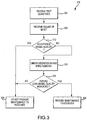
- Fig. 3 is a flow chart that illustrates the operation of the prediction module 256.
- the flow chart 300 illustrates a process of determining that a given receiver 204 requires maintenance at some future time within a defined time interval. The process illustrated by flow chart 300 may be repeated as needed for each receiver 204 being analyzed.
- the prediction module 256 receives test quantities from the test quantity module 248. As described above, each receiver 204 is associated with a time series of test quantities calculated by the test quantity module 248 using equation (3).
- operation 308 may be executed.
- the prediction module 256 receives a figure of merit for each receiver 204 depending on the receiver's geographic locale. As described above, a figure of merit may be calculated by using equation (4).
- the prediction module may consider a group of receivers that have a common geographic locale. In this case, operation 308 may include receiving a signal figure of merit from the figure of merit module 252. Operation 312 may be executed following operation 308.
- the prediction module 256 uses the time series of test quantities and the figure of merit to determine if the signal quality for a particular receiver 204 is acceptable. These discrete quantities are used to screen out receivers that can be identified as having a signal quality that is not likely to fall to an unacceptable level during the time interval.
- the prediction module 256 makes a rough calculation based on whether the values of TQ are greater than the FoM, based on whether the TQs are increasing or not, and based on the definition of a window. Specifically, the prediction module may select two subsets of these points by means of two integers n ⁇ m ⁇ window_size; and keeps only those receivers 204 that satisfy one of the following two conditions:
- operation 324 may be executed following operation 312. In operation, 324 the receiver is not considered a candidate for analysis, so the process may end. If the time series of test quantities and the figure of merit indicate that the signal quality is not necessarily acceptable, operation 316 may be executed following operation 312.
- prediction module applies a linear regression and spike removal technique to the time series of test quantities to produce a linear function for the receiver 204.
- the linear function produced in operation 316 includes a slope and an intercept.
- the process of linear regression and spike removal is described in greater detail below in connection with Fig. 4 .
- Operation 320 may be executed following operation 316.
- the slope and intercept obtained in operation 316 are used to determine if the receiver will experience an unacceptable signal quality at some future point during the time interval. This will be the case if the following inequality is satisfied: ⁇ ⁇ + ⁇ ⁇ slope + intercept ⁇ ⁇ ⁇ FoM .
- inequality (7) ⁇ is the window size and ⁇ and ⁇ are small constants.
- the actual values of parameters ⁇ and ⁇ are not meant to constrict the range of this algorithm. Such values are a matter of fine tuning.
- the left hand, or lower, side of this inequality is the value of the signal strength that should occur at the end of the processing period, at least according to the linear regression which was constructed for the receiver.
- the right hand, or upper, side of the inequality represents a marginal value of signal strength.
- inequality (7) may be interpreted to say that the receiver in question is predicted to have a very low level of signal strength at the end of the window, possibly even negative. The existence of such receivers can be demonstrated on the basis of the statistical properties of communication channels.
- operation 324 may follow operation 320.
- the linear function derived for the receiver 204 indicates that an unacceptable signal quality will not occur at a future time within the time interval.
- operation 328 may follow operation 320.
- the linear function derived for the receiver 204 indicates that an unacceptable signal quality will occur at a future time within the time interval.
- the prediction module 256 predicts a future poor signal quality for a particular receiver 204, and so the service provider 104 may initiate a maintenance call or "truck roll" for the household 108a-n associated with particular receiver 204.
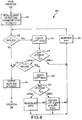
- a flow chart 400 is shown which illustrates a linear regression and spike removal method in accordance with implementations discussed herein.
- Flow chart 400 is a further explanation of operation 316 shown in Fig. 3 .
- signal histories are generally noisy, but such noise appears to be superimposed over straight segments which are separated by sudden jumps.
- the linear regression can be applied. Sudden jumps can be detected and removed by formulating the technique of linear regression in a recursive manner.
- General concepts of recursive linear regression will first be discussed. Following this, a linear regression and spike removal method in accordance will embodiments discussed herein will be discussed.
- the input data may be expressed as a pair of n -dimensional vectors, say x and y , respectively.
- the slope and intercept can be computed in batch mode, where all the information is handled at once. However, there are situations in which it is better to process each point separately, as it arrives.
- the prediction module 256 initializes a state vector for the receiver.
- a determination is made about the most recent value ⁇ n + 1 n . It is 'large' whenever it is found to lie k sigma outside the mean. Otherwise, the error is said to be 'small'. In the latter situation, the prediction module 256 decides that the signal is tracking according to the current straight line, and the operation passes to the next input point (operation 420).
- operation 428 follows operation 416.
- operation 428 there are two possibilities to consider: either the signal has jumped to a new linear segment (operation 436), or else a spike has been encountered (operation 440).
- the latter generally represents a transient condition in the broadcast, say as caused by a weather outage, or a power surge. The change may be a sudden increase or decrease; but either way, the prediction module 256 decides that the disturbance will be gone when the next data point is obtained.
- the prediction module 256 assumes that a new line segment has been encountered; and this requires a new sequence of state vectors be constructed. In this case, the state vector is re-initialized (operation 436); and processing returns to the input stream to pick up the next data point (operation 420).
- the new error is small (operation 440)
- it is assumed that the original jump was, in fact, a temporary phenomenon. That value of the input data is removed from consideration; and the operation passes to the next available point (operation 420).
- the output of the processing (operation 444) of flow chart 400 is the slope a and intercept b as found in the final state vector ⁇ ⁇ N .
- the algorithm of method shown in Fig. 4 may be "fine tuned.”
- the look-forward from n + 1 to n +2, certainly depends upon the granularity of the input data, and may be adjusted accordingly. That is, the look-forward may use more than two additional states.
- the notions of 'large' and 'small' depend upon the choice of the number, k , of sigma as mentioned above. This may be chosen to be the value two or three, but other values certainly fall within the purview of this algorithm.
- the re-initialization operation (operation 436) at the bottom the diagram has not been indicated, but any reasonable method is included within the scope of the overall algorithm.
Landscapes
- Engineering & Computer Science (AREA)
- Signal Processing (AREA)
- Multimedia (AREA)
- Computer Networks & Wireless Communication (AREA)
- Databases & Information Systems (AREA)
- Quality & Reliability (AREA)
- Health & Medical Sciences (AREA)
- Biomedical Technology (AREA)
- General Health & Medical Sciences (AREA)
- Electromagnetism (AREA)
- Computer Graphics (AREA)
- Physics & Mathematics (AREA)
- Monitoring And Testing Of Transmission In General (AREA)
- Telephonic Communication Services (AREA)
Claims (15)
- Verfahren zur Bereitstellung von Wartung für einen Empfänger (204), umfassend:Bestimmen einer Zeitreihe an Testmengen für einen Empfänger (304), wobei die Testmengen auf Signalstärkemessungen basieren, erfasst an dem Empfänger zu einer Vielzahl von Zeitpunkten; undEmpfangen einer Gütezahl für den Receiver (308), wobei die Gütezahl eine erwartete Signalqualität für den Empfänger angibt, wobei das Verfahren gekennzeichnet ist durchAnwenden linearer Regression auf die Zeitreihe an Testmengen und die Gütezahl, um eine lineare Funktion zu produzieren (316);Bestimmen einer Fehlervorhersage für den Empfänger basierend auf der linearen Funktion (320, 400); undIdentifizieren des Empfängers zur Wartung, falls die Fehlervorhersage eine zukünftige unakzeptable Signalstärke für den Empfänger angibt (328).
- Verfahren nach Anspruch 1, ferner umfassend:Ausschließen des Empfängers als Kandidat für Fehlervorhersage, falls die Zeitreihe an Testmengen für eine zuvor festgelegte Anzahl an Zeitpunkten keinen Abwärtstrend zeigt; und Ausschließen des Empfängers als Kandidat für Fehlervorhersage, falls die Zeitreihe an Testmengen für eine zuvor festgelegte Anzahl an Zeitpunkten nicht unterhalb der Gütezahl liegt (312),wobei die Handlung des Bestimmens einer Fehlervorhersage nur durchgeführt wird, falls der Empfänger nicht als Kandidat für Fehlervorhersage ausgeschlossen wird.
- Verfahren nach Anspruch 1 oder Anspruch 2, wobei die lineare Regression rekursiv ist.
- Verfahren nach Anspruch 3, ferner umfassend:Zurückweisen einer bestimmten Testmenge von der linearen Regression, falls die bestimmte Testmenge einen transienten Zustand angibt.
- Verfahren nach Anspruch 4, ferner umfassend:Berechnen eines ersten Fehlers für eine lineare Funktion basierend auf dem bestimmten Testzustand (412), wobei der erste Fehler einer vorhergesagten Signalstärke für einen ersten Zeitpunkt folgend auf einen Zeitpunkt der bestimmten Testmenge entspricht;falls der erste Fehler größer als eine zuvor festgelegte Fehlerschwelle ist (416), Berechnen eines zweiten Fehlers für die lineare Funktion basierend auf dem bestimmten Testzustand (428), wobei der zweite Fehler einer vorhergesagten Signalstärke für einen zweiten Zeitpunkt folgend auf den Zeitpunkt der bestimmten Testmenge entspricht; undfalls der zweite Fehler geringer als eine zuvor festgelegte Fehlerschwelle ist (432), Bestimmen, dass die bestimmte Testmenge einen transienten Zustand angibt.
- Verfahren nach Anspruch 1, wobei die Gütezahl eine erwartete Signalqualität für Empfänger in einer geographischen Region, in der sich der Empfänger befindet, angibt.
- Verfahren zur Bereitstellung von Wartung für eine Vielzahl von Empfängern, umfassend:Empfangen von Signalhistorien für eine erste Gruppe an Empfängern;Identifizieren einer zweiten Gruppe an Empfängern aus der ersten Gruppe an Empfängern, wobei die zweite Gruppe an Empfängern eine Signalstärke mit Abwärtstrend und eine Signalstärke unterhalb einer zuvor festgelegten Stufe für zumindest einen Zeitpunkt aufweist;Bearbeiten jedes Empfängers der zweiten Gruppe an Empfängern nach Anspruch 1;Identifizieren einer dritten Gruppe an Empfängern durch Auswahl derjenigen zur Wartung identifizierten Empfängern aus der zweiten Gruppe an Empfängern, falls die Fehlervorhersage die zukünftige inakzeptable Signalstärke für den jeweiligen Empfänger angibt; undMarkieren der dritten Gruppe an Empfängern zur Wartung.
- Verfahren nach Anspruch 7, ferner umfassend:Definieren einer ganzen Zahl W als eine Fenstergröße;Bestimmen einer Testmenge für jeden Empfänger in der ersten Gruppe für jeden von letzten W Zeitpunkten zum Bilden der bestimmten Zeitreihe an Testmengen für jeden Empfänger; undBestimmen einer Gütezahl für jeden aus einer Anzahl von geographischen Orten zum Bilden der empfangenen Gütezahl für jeden Empfänger, wobei jeder Empfänger in der ersten Gruppe an Empfängern zu einem der geographischen Orte gehört;wobei die Handlungen des Identifizierens der zweiten Gruppe an Empfängern, Anwendens linearer Regression zum Produzieren der linearen Funktion und Identifizierens der dritten Gruppe an Empfängern für jeden der letzten W Zeitpunkte unter Verwendung von Testmengen für jeden Empfänger und der Gütezahl für jeden geographischen Ort durchgeführt werden.
- Verfahren nach Anspruch 8, wobei das Bestimmen der Gütezahl für jeden der geographischen Orte Folgendes beinhaltet:Bestimmen eines starken Kanals und eines schwachen Kanals für den geographischen Ort;Definieren eines Mindestwertes an akzeptablem Signalempfang für den starken Kanal;Definieren eines Höchstwertes an unakzeptablem Signalempfang für den starken Kanal;Definieren eines Mindestwertes an akzeptablem Signalempfang für den schwachen Kanal;Definieren eines Höchstwertes an unakzeptablem Signalempfang für den schwachen Kanal;Berechnen einer ersten Zwischenmenge durch Nehmen der Quadratwurzel des Produkts des Mindestwertes an akzeptablem Signalempfang für den starken Kanal und des Höchstwertes an unakzeptablem Signalempfang für den schwachen Kanal;Berechnen einer zweiten Zwischenmenge durch Nehmen der Quadratwurzel des Produkts des Höchstwertes an unakzeptablem Signalempfang für den starken Kanal und des Mindestwertes an akzeptablem Signalempfang für den schwachen Kanal; undDefinieren, dass die Gütezahl die geringere der ersten Zwischenmenge und der zweiten Zwischenmenge ist.
- Verfahren nach Anspruch 8, wobei das Produzieren der linearen Funktion Folgendes umfasst:(a) Festlegen einer Zustandsfunktion basierend auf einer Testmenge und einer Gütezahl für einen Testzeitpunkt, wobei die Zustandsfunktion eine Steigung und einen Achsenabschnitt beinhaltet;(b) Bestimmen eines ersten Fehlers, der auftritt, wenn eine Signalqualität für einen ersten Zeitpunkt folgend auf den Testzeitpunkt basierend auf der Zustandsfunktion geschätzt wird;(c) falls der erste Fehler geringer als eine Fehlerschwelle ist, Erhöhen des Testzeitpunktes auf einen nächsten folgenden Zeitpunkt und Wiederholen der Handlung (b), falls ein folgender Zeitpunkt vorhanden ist;(d) falls der erste Fehler größer als die Fehlerschwelle ist, Bestimmen eines zweiten Fehlers, der auftritt, wenn eine Signalqualität für einen zweiten Zeitpunkt folgend auf den Testzeitpunkt basierend auf der Zustandsfunktion geschätzt wird;(e) falls der zweite Fehler geringer als die Fehlerschwelle ist, Ignorieren des Testzeitpunktes, Erhöhen des Testzeitpunktes auf einen nächsten folgenden Zeitpunkt und Wiederholen der Handlung (b), falls ein folgender Zeitpunkt vorhanden ist;(f) falls der zweite Fehler weniger größer als die Fehlerschwelle ist, Zurücksetzen der Zustandsfunktion basierend auf einer Testmenge und einer Gütezahl für den ersten Zeitpunkt folgend auf den Testzeitpunkt, Erhöhen des Testzeitpunktes auf einen nächsten folgenden Zeitpunkt und Wiederholen der Handlung (b), falls ein folgender Zeitpunkt vorhanden ist; und(g) Definieren der linearen Funktion basierend auf der Steigung und dem Achsenabschnitt der Zustandsfunktion der Zustandsfunktion resultierend aus den Handlungen (a) bis (f).
- Verfahren nach Anspruch 8, wobei das Identifizieren der dritten Gruppe an Empfängern Folgendes umfasst:Definieren einer ersten Konstante;Berechnen einer ersten Menge als das Produkt der Steigung und der Summe der ersten Konstante;Berechnen einer zweiten Menge als die Summe der ersten Menge und des Achsenabschnittes;Definieren einer zweiten Konstante; undBerechnen einer dritten Menge als Produkt der zweiten Konstante und der Gütezahl;wobei die zweite Menge geringer als die dritte Menge für jeden Empfänger ausgewählt aus der zweiten Gruppe an Empfängern ist.
- System (104) zur Bereitstellung von Wartung für einen Empfänger (204), umfassend:ein Testmengenmodul (248), das bedienbar ist, um eine Zeitreihe an Testmengen für einen Empfänger basierend auf Signalstärkemessungen, erfasst an dem Empfänger zu einer Vielzahl von Zeitpunkten, zu bestimmen;ein Gütezahlenmodul (252), das bedienbar ist, um eine Gütezahl für den Empfänger zu empfangen, wobei die Gütezahl eine erwartete Signalqualität für den Empfänger angibt; undein Vorhersagemodul (256), das bedienbar ist, um eine Fehlervorhersage für den Empfänger mit einer unakzeptablen Signalstärke in der Zukunft basierend auf einer linearen Regressionsfunktion, berechnet aus der Zeitreihe an Testmengen und der Gütezahl, zu bestimmen.
- System nach Anspruch 12, wobei das Vorhersagemodul (256) ferner bedienbar ist, um:den Empfänger als Kandidat für Fehlervorhersage auszuschließen, falls die Zeitreihe an Testmengen für eine zuvor festgelegte Anzahl an Zeitpunkten nicht abwärts tendiert; undden Empfänger als Kandidat für Fehlervorhersage auszuschließen, falls die Zeitreihe an Testmengen für einen zuvor festgelegten Zeitraum nicht unterhalb der Gütezahl liegt;wobei das Fehlervorhersagemodul eine Fehlervorhersage für den Empfänger nur dann bestimmt, falls der Empfänger nicht als Kandidat für Fehlervorhersage ausgeschlossen wird.
- System nach Anspruch 12, wobei das Vorhersagemodul (256) ferner bedienbar ist, um:lineare Regression auf die Zeitreihe an Testmengen anzuwenden, um die lineare Funktion zu produzieren, wobei die lineare Regression rekursiv ist; undeine bestimmte Testmenge von der linearen Regression zurückzuweisen, falls die bestimmte Testmenge einen transienten Zustand angibt.
- System nach Anspruch 14, wobei das Vorhersagemodul (256) ferner bedienbar ist, um:einen ersten Fehler für eine lineare Funktion basierend auf dem bestimmten Testzustand zu berechnen, wobei der erste Fehler einer vorhergesagten Signalstärke für einen ersten Zeitpunkt folgend auf einen Zeitpunkt der bestimmten Testmenge entspricht;falls der erste Fehler größer als eine zuvor festgelegte Fehlerschwelle ist, einen zweiten Fehler für die lineare Funktion basierend auf dem bestimmten Testzustand zu berechnen, wobei der zweite Fehler einer vorhergesagten Signalstärke für einen zweiten Zeitpunkt folgend auf den Zeitpunkt der bestimmten Testmenge entspricht; undfalls der zweite Fehler geringer als eine zuvor festgelegte Fehlerschwelle ist, zu bestimmen, dass die bestimmte Testmenge einen transienten Zustand angibt.
Applications Claiming Priority (2)
| Application Number | Priority Date | Filing Date | Title |
|---|---|---|---|
| US12/823,789 US8364107B2 (en) | 2010-06-25 | 2010-06-25 | Signal degradation detection |
| PCT/US2011/036226 WO2011162885A1 (en) | 2010-06-25 | 2011-05-12 | Signal degradation detection |
Publications (2)
| Publication Number | Publication Date |
|---|---|
| EP2586192A1 EP2586192A1 (de) | 2013-05-01 |
| EP2586192B1 true EP2586192B1 (de) | 2016-03-16 |
Family
ID=44261744
Family Applications (1)
| Application Number | Title | Priority Date | Filing Date |
|---|---|---|---|
| EP11724083.8A Active EP2586192B1 (de) | 2010-06-25 | 2011-05-12 | Erkennung von signalverschlechterung |
Country Status (8)
| Country | Link |
|---|---|
| US (2) | US8364107B2 (de) |
| EP (1) | EP2586192B1 (de) |
| CN (1) | CN102959982B (de) |
| BR (1) | BR112012032679B1 (de) |
| CA (1) | CA2803778C (de) |
| MX (1) | MX2012014964A (de) |
| TW (1) | TWI469626B (de) |
| WO (1) | WO2011162885A1 (de) |
Families Citing this family (17)
| Publication number | Priority date | Publication date | Assignee | Title |
|---|---|---|---|---|
| US8364107B2 (en) * | 2010-06-25 | 2013-01-29 | Echostar Technologies L.L.C. | Signal degradation detection |
| BR112014014661B1 (pt) | 2011-12-20 | 2021-12-28 | Abs Global, Ltd | Método para a comunicação para um destino por múltiplos links de satélite e aparelho de destino para a recepção de dados por múltiplos links via satélite |
| US10237144B2 (en) | 2012-10-29 | 2019-03-19 | T-Mobile Usa, Inc. | Quality of user experience analysis |
| US10313905B2 (en) | 2012-10-29 | 2019-06-04 | T-Mobile Usa, Inc. | Contextual quality of user experience analysis using equipment dynamics |
| US10412550B2 (en) | 2012-10-29 | 2019-09-10 | T-Mobile Usa, Inc. | Remote driving of mobile device diagnostic applications |
| US10952091B2 (en) | 2012-10-29 | 2021-03-16 | T-Mobile Usa, Inc. | Quality of user experience analysis |
| US9538409B2 (en) | 2012-10-29 | 2017-01-03 | T-Mobile Usa, Inc. | Quality of user experience analysis |
| US9420477B2 (en) | 2014-06-04 | 2016-08-16 | Grandios Technologies, Llc | Signal strength management |
| GB2544488B (en) | 2015-11-17 | 2019-01-02 | Samsung Electronics Co Ltd | Radio frequency analysis using television tuner |
| WO2017116853A1 (en) * | 2015-12-30 | 2017-07-06 | T-Mobile Usa, Inc. | Contextual quality of user experience analysis using equipment dynamics |
| US10582262B2 (en) | 2016-06-30 | 2020-03-03 | At&T Intellectual Property I, L.P. | Satellite video content delivery system |
| US10419796B2 (en) | 2017-03-02 | 2019-09-17 | The Directv Group, Inc. | Broadband backup to satellite-based set-top boxes |
| US11039364B2 (en) | 2018-09-28 | 2021-06-15 | Google Llc | Methods and apparatus for proactively switching between available networks |
| FI129590B (en) | 2020-12-03 | 2022-05-13 | Elisa Oyj | Method and equipment for detecting and remedying a fault in a fixed data transmission connection |
| CN115249075B (zh) * | 2022-09-22 | 2022-12-06 | 国网山西省电力公司太原供电公司 | 一种电缆隧道的安全运维管理方法及系统 |
| WO2024115984A1 (en) * | 2022-11-28 | 2024-06-06 | Tata Play Limited | Method and system for monitoring multimedia streaming channels |
| CN116248959B (zh) * | 2023-05-12 | 2023-07-28 | 深圳市橙视科技发展有限公司 | 网络播放器故障检测方法、装置、设备及存储介质 |
Family Cites Families (10)
| Publication number | Priority date | Publication date | Assignee | Title |
|---|---|---|---|---|
| US5235619A (en) | 1990-03-20 | 1993-08-10 | Scientific-Atlanta, Inc. | Cable television radio frequency subscriber data transmission apparatus and rf return method |
| US5835857A (en) * | 1990-03-19 | 1998-11-10 | Celsat America, Inc. | Position determination for reducing unauthorized use of a communication system |
| US5142690A (en) * | 1990-03-20 | 1992-08-25 | Scientific-Atlanta, Inc. | Cable television radio frequency data processor |
| WO1998010307A1 (en) * | 1996-09-09 | 1998-03-12 | Dennis Jay Dupray | Location of a mobile station |
| US6445907B1 (en) | 1998-04-16 | 2002-09-03 | Hughes Electronics Corporation | Method and system for remote diagnostics of a satellite receiver |
| US20030028891A1 (en) | 2001-08-03 | 2003-02-06 | General Instrument Corporation | System and method for diagnosing RF signal strength at a set-top terminal |
| US7308492B2 (en) * | 2002-10-02 | 2007-12-11 | Sony Corporation | Method and apparatus for use in remote diagnostics |
| US7367039B2 (en) | 2003-05-22 | 2008-04-29 | The Directv Group, Inc. | System and method for evaluating callback functionality in a satellite television network |
| US20050114879A1 (en) | 2003-11-20 | 2005-05-26 | General Instrument Corporation | Monitoring signal quality on a cable network |
| US8364107B2 (en) * | 2010-06-25 | 2013-01-29 | Echostar Technologies L.L.C. | Signal degradation detection |
-
2010
- 2010-06-25 US US12/823,789 patent/US8364107B2/en active Active
-
2011
- 2011-05-12 WO PCT/US2011/036226 patent/WO2011162885A1/en not_active Ceased
- 2011-05-12 BR BR112012032679-1A patent/BR112012032679B1/pt active IP Right Grant
- 2011-05-12 MX MX2012014964A patent/MX2012014964A/es active IP Right Grant
- 2011-05-12 CA CA2803778A patent/CA2803778C/en active Active
- 2011-05-12 EP EP11724083.8A patent/EP2586192B1/de active Active
- 2011-05-12 CN CN201180031586.2A patent/CN102959982B/zh active Active
- 2011-06-23 TW TW100122071A patent/TWI469626B/zh active
-
2012
- 2012-12-21 US US13/725,295 patent/US8824989B2/en active Active
Also Published As
| Publication number | Publication date |
|---|---|
| US20130109336A1 (en) | 2013-05-02 |
| TWI469626B (zh) | 2015-01-11 |
| WO2011162885A1 (en) | 2011-12-29 |
| US8364107B2 (en) | 2013-01-29 |
| CA2803778A1 (en) | 2011-12-29 |
| EP2586192A1 (de) | 2013-05-01 |
| CA2803778C (en) | 2016-02-02 |
| CN102959982A (zh) | 2013-03-06 |
| BR112012032679A2 (pt) | 2016-11-22 |
| CN102959982B (zh) | 2015-12-02 |
| BR112012032679B1 (pt) | 2021-09-28 |
| MX2012014964A (es) | 2013-02-26 |
| TW201215114A (en) | 2012-04-01 |
| US20110319043A1 (en) | 2011-12-29 |
| US8824989B2 (en) | 2014-09-02 |
Similar Documents
| Publication | Publication Date | Title |
|---|---|---|
| EP2586192B1 (de) | Erkennung von signalverschlechterung | |
| US11330343B2 (en) | Dynamic viewer prediction system for advertisement scheduling | |
| US20100309317A1 (en) | Device and method for detecting unused tv spectrum for wireless communication systems | |
| US20170013587A1 (en) | Method and system for dynamically adjusting communication characteristics of satellite communication links based on weather nowcasting | |
| US11496885B2 (en) | Determining the operational characteristics and configuration for wireless devices | |
| Fabbro et al. | Characterization and modelling of time diversity statistics for satellite communications from 12 to 50 GHz | |
| EP3731439A1 (de) | Reflexionsratenmessvorrichtung für rundfunkdienst | |
| EP3731440A1 (de) | Vorrichtung zur messung der bounce-rate eines rundfunkdienstes | |
| US20200036462A1 (en) | Prediction Method And Device | |
| Panagopoulos et al. | Adjacent satellite interference effects as applied to the outage performance of an earth-space system located in a heavy rain climatic region | |
| EP3301833A1 (de) | Verfahren zur hochfrequenten (hf) abtastung zur diagnose und vorwegnahme von empfangsproblemen auf grundlage von fehlermodellierung | |
| EP2234371B1 (de) | Verfahren zur Beschleunigung der Kanalumschaltung in IP-Fernsehprodukten | |
| EP4449166B1 (de) | Verfahren und vorrichtung zur wetterdetektion mittels satelliten | |
| JP7559440B2 (ja) | 放送信号処理装置、放送信号処理システムおよび放送信号処理方法 | |
| Lin et al. | Analysis of ATSC field test results in Taiwan | |
| JP2012127932A (ja) | 地上デジタル放送環境を利用した地震予知システム | |
| KR0165941B1 (ko) | 위성통신 시스템을 위한 무인 단말지구국 시스템 및 이를 위한 지구국의 상태 점검방법 | |
| Kamei et al. | A study of rain attenuation with measured data in Japan for 21GHz-band satellite broadcasting | |
| JP2002259752A (ja) | サービスにおける障害を対象とした保険のための保険料率の決定方法 | |
| KR20150064861A (ko) | 위성방송신호지상파방송신호겸용수신안테나, 위성수신과 지상파수신 방송 겸용수신처리방법 및 겸용수신기 |
Legal Events
| Date | Code | Title | Description |
|---|---|---|---|
| PUAI | Public reference made under article 153(3) epc to a published international application that has entered the european phase |
Free format text: ORIGINAL CODE: 0009012 |
|
| 17P | Request for examination filed |
Effective date: 20121213 |
|
| AK | Designated contracting states |
Kind code of ref document: A1 Designated state(s): AL AT BE BG CH CY CZ DE DK EE ES FI FR GB GR HR HU IE IS IT LI LT LU LV MC MK MT NL NO PL PT RO RS SE SI SK SM TR |
|
| DAX | Request for extension of the european patent (deleted) | ||
| REG | Reference to a national code |
Ref country code: DE Ref legal event code: R079 Ref document number: 602011024052 Country of ref document: DE Free format text: PREVIOUS MAIN CLASS: H04N0005000000 Ipc: H04N0021258000 |
|
| GRAP | Despatch of communication of intention to grant a patent |
Free format text: ORIGINAL CODE: EPIDOSNIGR1 |
|
| RIC1 | Information provided on ipc code assigned before grant |
Ipc: H04N 21/61 20110101ALI20150918BHEP Ipc: H04N 17/00 20060101ALI20150918BHEP Ipc: H04N 21/658 20110101ALI20150918BHEP Ipc: H04N 21/442 20110101ALI20150918BHEP Ipc: H04B 17/373 20150101ALI20150918BHEP Ipc: H04L 12/24 20060101ALI20150918BHEP Ipc: H04N 21/258 20110101AFI20150918BHEP Ipc: H04L 12/26 20060101ALI20150918BHEP |
|
| INTG | Intention to grant announced |
Effective date: 20151006 |
|
| GRAS | Grant fee paid |
Free format text: ORIGINAL CODE: EPIDOSNIGR3 |
|
| GRAA | (expected) grant |
Free format text: ORIGINAL CODE: 0009210 |
|
| AK | Designated contracting states |
Kind code of ref document: B1 Designated state(s): AL AT BE BG CH CY CZ DE DK EE ES FI FR GB GR HR HU IE IS IT LI LT LU LV MC MK MT NL NO PL PT RO RS SE SI SK SM TR |
|
| REG | Reference to a national code |
Ref country code: GB Ref legal event code: FG4D Ref country code: NL Ref legal event code: FP |
|
| REG | Reference to a national code |
Ref country code: CH Ref legal event code: EP |
|
| REG | Reference to a national code |
Ref country code: IE Ref legal event code: FG4D |
|
| REG | Reference to a national code |
Ref country code: AT Ref legal event code: REF Ref document number: 782087 Country of ref document: AT Kind code of ref document: T Effective date: 20160415 |
|
| REG | Reference to a national code |
Ref country code: FR Ref legal event code: PLFP Year of fee payment: 6 |
|
| REG | Reference to a national code |
Ref country code: DE Ref legal event code: R096 Ref document number: 602011024052 Country of ref document: DE |
|
| REG | Reference to a national code |
Ref country code: LT Ref legal event code: MG4D |
|
| PG25 | Lapsed in a contracting state [announced via postgrant information from national office to epo] |
Ref country code: FI Free format text: LAPSE BECAUSE OF FAILURE TO SUBMIT A TRANSLATION OF THE DESCRIPTION OR TO PAY THE FEE WITHIN THE PRESCRIBED TIME-LIMIT Effective date: 20160316 Ref country code: HR Free format text: LAPSE BECAUSE OF FAILURE TO SUBMIT A TRANSLATION OF THE DESCRIPTION OR TO PAY THE FEE WITHIN THE PRESCRIBED TIME-LIMIT Effective date: 20160316 Ref country code: GR Free format text: LAPSE BECAUSE OF FAILURE TO SUBMIT A TRANSLATION OF THE DESCRIPTION OR TO PAY THE FEE WITHIN THE PRESCRIBED TIME-LIMIT Effective date: 20160617 Ref country code: NO Free format text: LAPSE BECAUSE OF FAILURE TO SUBMIT A TRANSLATION OF THE DESCRIPTION OR TO PAY THE FEE WITHIN THE PRESCRIBED TIME-LIMIT Effective date: 20160616 |
|
| REG | Reference to a national code |
Ref country code: AT Ref legal event code: MK05 Ref document number: 782087 Country of ref document: AT Kind code of ref document: T Effective date: 20160316 |
|
| PG25 | Lapsed in a contracting state [announced via postgrant information from national office to epo] |
Ref country code: SE Free format text: LAPSE BECAUSE OF FAILURE TO SUBMIT A TRANSLATION OF THE DESCRIPTION OR TO PAY THE FEE WITHIN THE PRESCRIBED TIME-LIMIT Effective date: 20160316 Ref country code: RS Free format text: LAPSE BECAUSE OF FAILURE TO SUBMIT A TRANSLATION OF THE DESCRIPTION OR TO PAY THE FEE WITHIN THE PRESCRIBED TIME-LIMIT Effective date: 20160316 Ref country code: BE Free format text: LAPSE BECAUSE OF NON-PAYMENT OF DUE FEES Effective date: 20160531 Ref country code: LV Free format text: LAPSE BECAUSE OF FAILURE TO SUBMIT A TRANSLATION OF THE DESCRIPTION OR TO PAY THE FEE WITHIN THE PRESCRIBED TIME-LIMIT Effective date: 20160316 Ref country code: LT Free format text: LAPSE BECAUSE OF FAILURE TO SUBMIT A TRANSLATION OF THE DESCRIPTION OR TO PAY THE FEE WITHIN THE PRESCRIBED TIME-LIMIT Effective date: 20160316 |
|
| PG25 | Lapsed in a contracting state [announced via postgrant information from national office to epo] |
Ref country code: PL Free format text: LAPSE BECAUSE OF FAILURE TO SUBMIT A TRANSLATION OF THE DESCRIPTION OR TO PAY THE FEE WITHIN THE PRESCRIBED TIME-LIMIT Effective date: 20160316 Ref country code: IS Free format text: LAPSE BECAUSE OF FAILURE TO SUBMIT A TRANSLATION OF THE DESCRIPTION OR TO PAY THE FEE WITHIN THE PRESCRIBED TIME-LIMIT Effective date: 20160716 Ref country code: EE Free format text: LAPSE BECAUSE OF FAILURE TO SUBMIT A TRANSLATION OF THE DESCRIPTION OR TO PAY THE FEE WITHIN THE PRESCRIBED TIME-LIMIT Effective date: 20160316 |
|
| PG25 | Lapsed in a contracting state [announced via postgrant information from national office to epo] |
Ref country code: RO Free format text: LAPSE BECAUSE OF FAILURE TO SUBMIT A TRANSLATION OF THE DESCRIPTION OR TO PAY THE FEE WITHIN THE PRESCRIBED TIME-LIMIT Effective date: 20160316 Ref country code: CZ Free format text: LAPSE BECAUSE OF FAILURE TO SUBMIT A TRANSLATION OF THE DESCRIPTION OR TO PAY THE FEE WITHIN THE PRESCRIBED TIME-LIMIT Effective date: 20160316 Ref country code: PT Free format text: LAPSE BECAUSE OF FAILURE TO SUBMIT A TRANSLATION OF THE DESCRIPTION OR TO PAY THE FEE WITHIN THE PRESCRIBED TIME-LIMIT Effective date: 20160718 Ref country code: SK Free format text: LAPSE BECAUSE OF FAILURE TO SUBMIT A TRANSLATION OF THE DESCRIPTION OR TO PAY THE FEE WITHIN THE PRESCRIBED TIME-LIMIT Effective date: 20160316 Ref country code: ES Free format text: LAPSE BECAUSE OF FAILURE TO SUBMIT A TRANSLATION OF THE DESCRIPTION OR TO PAY THE FEE WITHIN THE PRESCRIBED TIME-LIMIT Effective date: 20160316 Ref country code: SM Free format text: LAPSE BECAUSE OF FAILURE TO SUBMIT A TRANSLATION OF THE DESCRIPTION OR TO PAY THE FEE WITHIN THE PRESCRIBED TIME-LIMIT Effective date: 20160316 Ref country code: AT Free format text: LAPSE BECAUSE OF FAILURE TO SUBMIT A TRANSLATION OF THE DESCRIPTION OR TO PAY THE FEE WITHIN THE PRESCRIBED TIME-LIMIT Effective date: 20160316 |
|
| REG | Reference to a national code |
Ref country code: DE Ref legal event code: R097 Ref document number: 602011024052 Country of ref document: DE |
|
| PG25 | Lapsed in a contracting state [announced via postgrant information from national office to epo] |
Ref country code: IT Free format text: LAPSE BECAUSE OF FAILURE TO SUBMIT A TRANSLATION OF THE DESCRIPTION OR TO PAY THE FEE WITHIN THE PRESCRIBED TIME-LIMIT Effective date: 20160316 Ref country code: LU Free format text: LAPSE BECAUSE OF FAILURE TO SUBMIT A TRANSLATION OF THE DESCRIPTION OR TO PAY THE FEE WITHIN THE PRESCRIBED TIME-LIMIT Effective date: 20160512 Ref country code: BE Free format text: LAPSE BECAUSE OF FAILURE TO SUBMIT A TRANSLATION OF THE DESCRIPTION OR TO PAY THE FEE WITHIN THE PRESCRIBED TIME-LIMIT Effective date: 20160316 |
|
| REG | Reference to a national code |
Ref country code: CH Ref legal event code: PL |
|
| PLBE | No opposition filed within time limit |
Free format text: ORIGINAL CODE: 0009261 |
|
| STAA | Information on the status of an ep patent application or granted ep patent |
Free format text: STATUS: NO OPPOSITION FILED WITHIN TIME LIMIT |
|
| PG25 | Lapsed in a contracting state [announced via postgrant information from national office to epo] |
Ref country code: LI Free format text: LAPSE BECAUSE OF NON-PAYMENT OF DUE FEES Effective date: 20160531 Ref country code: DK Free format text: LAPSE BECAUSE OF FAILURE TO SUBMIT A TRANSLATION OF THE DESCRIPTION OR TO PAY THE FEE WITHIN THE PRESCRIBED TIME-LIMIT Effective date: 20160316 Ref country code: CH Free format text: LAPSE BECAUSE OF NON-PAYMENT OF DUE FEES Effective date: 20160531 |
|
| 26N | No opposition filed |
Effective date: 20161219 |
|
| REG | Reference to a national code |
Ref country code: IE Ref legal event code: MM4A |
|
| PG25 | Lapsed in a contracting state [announced via postgrant information from national office to epo] |
Ref country code: BG Free format text: LAPSE BECAUSE OF FAILURE TO SUBMIT A TRANSLATION OF THE DESCRIPTION OR TO PAY THE FEE WITHIN THE PRESCRIBED TIME-LIMIT Effective date: 20160616 |
|
| REG | Reference to a national code |
Ref country code: FR Ref legal event code: PLFP Year of fee payment: 7 |
|
| PG25 | Lapsed in a contracting state [announced via postgrant information from national office to epo] |
Ref country code: SI Free format text: LAPSE BECAUSE OF FAILURE TO SUBMIT A TRANSLATION OF THE DESCRIPTION OR TO PAY THE FEE WITHIN THE PRESCRIBED TIME-LIMIT Effective date: 20160316 Ref country code: IE Free format text: LAPSE BECAUSE OF NON-PAYMENT OF DUE FEES Effective date: 20160512 |
|
| REG | Reference to a national code |
Ref country code: FR Ref legal event code: PLFP Year of fee payment: 8 |
|
| PG25 | Lapsed in a contracting state [announced via postgrant information from national office to epo] |
Ref country code: HU Free format text: LAPSE BECAUSE OF FAILURE TO SUBMIT A TRANSLATION OF THE DESCRIPTION OR TO PAY THE FEE WITHIN THE PRESCRIBED TIME-LIMIT; INVALID AB INITIO Effective date: 20110512 Ref country code: CY Free format text: LAPSE BECAUSE OF FAILURE TO SUBMIT A TRANSLATION OF THE DESCRIPTION OR TO PAY THE FEE WITHIN THE PRESCRIBED TIME-LIMIT Effective date: 20160316 |
|
| PG25 | Lapsed in a contracting state [announced via postgrant information from national office to epo] |
Ref country code: MK Free format text: LAPSE BECAUSE OF FAILURE TO SUBMIT A TRANSLATION OF THE DESCRIPTION OR TO PAY THE FEE WITHIN THE PRESCRIBED TIME-LIMIT Effective date: 20160316 Ref country code: MC Free format text: LAPSE BECAUSE OF FAILURE TO SUBMIT A TRANSLATION OF THE DESCRIPTION OR TO PAY THE FEE WITHIN THE PRESCRIBED TIME-LIMIT Effective date: 20160316 Ref country code: TR Free format text: LAPSE BECAUSE OF FAILURE TO SUBMIT A TRANSLATION OF THE DESCRIPTION OR TO PAY THE FEE WITHIN THE PRESCRIBED TIME-LIMIT Effective date: 20160316 Ref country code: MT Free format text: LAPSE BECAUSE OF NON-PAYMENT OF DUE FEES Effective date: 20160531 |
|
| PG25 | Lapsed in a contracting state [announced via postgrant information from national office to epo] |
Ref country code: AL Free format text: LAPSE BECAUSE OF FAILURE TO SUBMIT A TRANSLATION OF THE DESCRIPTION OR TO PAY THE FEE WITHIN THE PRESCRIBED TIME-LIMIT Effective date: 20160316 |
|
| REG | Reference to a national code |
Ref country code: DE Ref legal event code: R082 Ref document number: 602011024052 Country of ref document: DE Representative=s name: HERNANDEZ, YORCK, DIPL.-ING., DE Ref country code: DE Ref legal event code: R081 Ref document number: 602011024052 Country of ref document: DE Owner name: DISH TECHNOLOGIES L.L.C., ENGLEWOOD, US Free format text: FORMER OWNER: ECHOSTAR TECHNOLOGIES L.L.C., ENGLEWOOD, COL., US |
|
| REG | Reference to a national code |
Ref country code: NL Ref legal event code: HC Owner name: DISH TECHNOLOGIES L.L.C.; US Free format text: DETAILS ASSIGNMENT: CHANGE OF OWNER(S), CHANGE OF OWNER(S) NAME; FORMER OWNER NAME: ECHOSTAR TECHNOLOGIES L.L.C. Effective date: 20190829 |
|
| P01 | Opt-out of the competence of the unified patent court (upc) registered |
Effective date: 20230521 |
|
| PGFP | Annual fee paid to national office [announced via postgrant information from national office to epo] |
Ref country code: DE Payment date: 20250319 Year of fee payment: 15 |
|
| PGFP | Annual fee paid to national office [announced via postgrant information from national office to epo] |
Ref country code: GB Payment date: 20260313 Year of fee payment: 16 |
|
| PGFP | Annual fee paid to national office [announced via postgrant information from national office to epo] |
Ref country code: NL Payment date: 20260317 Year of fee payment: 16 |
|
| PGFP | Annual fee paid to national office [announced via postgrant information from national office to epo] |
Ref country code: FR Payment date: 20260309 Year of fee payment: 16 |