EP2586121B1 - Split magnetic thrust bearing - Google Patents
Split magnetic thrust bearing Download PDFInfo
- Publication number
- EP2586121B1 EP2586121B1 EP11798908.7A EP11798908A EP2586121B1 EP 2586121 B1 EP2586121 B1 EP 2586121B1 EP 11798908 A EP11798908 A EP 11798908A EP 2586121 B1 EP2586121 B1 EP 2586121B1
- Authority
- EP
- European Patent Office
- Prior art keywords
- stator
- magnetic
- semi
- magnetic bearing
- thrust
- Prior art date
- Legal status (The legal status is an assumption and is not a legal conclusion. Google has not performed a legal analysis and makes no representation as to the accuracy of the status listed.)
- Active
Links
Images


Classifications
-
- H—ELECTRICITY
- H02—GENERATION; CONVERSION OR DISTRIBUTION OF ELECTRIC POWER
- H02K—DYNAMO-ELECTRIC MACHINES
- H02K7/00—Arrangements for handling mechanical energy structurally associated with dynamo-electric machines, e.g. structural association with mechanical driving motors or auxiliary dynamo-electric machines
- H02K7/08—Structural association with bearings
- H02K7/09—Structural association with bearings with magnetic bearings
-
- F—MECHANICAL ENGINEERING; LIGHTING; HEATING; WEAPONS; BLASTING
- F16—ENGINEERING ELEMENTS AND UNITS; GENERAL MEASURES FOR PRODUCING AND MAINTAINING EFFECTIVE FUNCTIONING OF MACHINES OR INSTALLATIONS; THERMAL INSULATION IN GENERAL
- F16C—SHAFTS; FLEXIBLE SHAFTS; ELEMENTS OR CRANKSHAFT MECHANISMS; ROTARY BODIES OTHER THAN GEARING ELEMENTS; BEARINGS
- F16C32/00—Bearings not otherwise provided for
- F16C32/04—Bearings not otherwise provided for using magnetic or electric supporting means
- F16C32/0406—Magnetic bearings
- F16C32/044—Active magnetic bearings
- F16C32/0459—Details of the magnetic circuit
-
- F—MECHANICAL ENGINEERING; LIGHTING; HEATING; WEAPONS; BLASTING
- F16—ENGINEERING ELEMENTS AND UNITS; GENERAL MEASURES FOR PRODUCING AND MAINTAINING EFFECTIVE FUNCTIONING OF MACHINES OR INSTALLATIONS; THERMAL INSULATION IN GENERAL
- F16C—SHAFTS; FLEXIBLE SHAFTS; ELEMENTS OR CRANKSHAFT MECHANISMS; ROTARY BODIES OTHER THAN GEARING ELEMENTS; BEARINGS
- F16C32/00—Bearings not otherwise provided for
- F16C32/04—Bearings not otherwise provided for using magnetic or electric supporting means
- F16C32/0406—Magnetic bearings
- F16C32/044—Active magnetic bearings
- F16C32/0474—Active magnetic bearings for rotary movement
- F16C32/0476—Active magnetic bearings for rotary movement with active support of one degree of freedom, e.g. axial magnetic bearings
Definitions
- Document US 5,455,472 discloses a magnetic bearing assembly, which provides for correction of shaft deflection, or "bowing", during rotation of the shaft.
- the assembly comprises two stator rings in spaced relation to each other, and each stator ring comprises a plurality of stator sections which are independently activated.
- sensors detect the deflection and independently activate the various stator sections producing a force couple which acts on the rotor to produce a bending moment in the shaft which tends to counteract the "bowing”.
- Document US 4,920,291 discloses an electromagnetic axial thrust bearing comprising a rotating member, at least one stationary member and a winding for generating a magneto motive force associated with the stationary member.
- the stationary member is comprised of a solid ferromagnetic material having at least one arc-shaped groove substantially concentric with the turning axis of the rotating member.
- the groove is lined with laminates of a ferromagnetic material.
- the winding is laid into the lined groove of the stationary member.
- Certain exemplary embodiments can provide a system, machine, device, manufacture, circuit, composition of matter, and/or user interface adapted for and/or resulting from, and/or a method and/or machine-readable medium comprising machine-implementable instructions for, activities that can comprise and/or relate to: via a thrust stator of a magnetic bearing, the thrust stator adapted to be split into sectors so that a shaft of a machine can be removed from the magnetic bearing, producing an axi-symmetric field at each pole face of the thrust stator when the sectors are operatively assembled in the machine; and/or a magnetic bearing thrust stator, comprising a plurality of stator sectors, each of the stator sectors comprising a semi-circumferentially slotted stator portion comprising a plurality of semi-circumferential poles and a first coil portion shaped to fit substantially within the semi-circumferentially slotted stator portion.
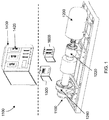
- FIG. 1 shows a perspective view of an exemplary magnetic bearing system 1000, which can include a rotating machine 1100 supported via magnetic bearings.
- rotating machines 1100 that can benefit from magnetic bearings can include compressors, blowers, pumps, turbines, motors, and generators.
- Certain rotating machines can include a drive motor 1200 for powering the rotating machine.
- magnetic bearing system 1000 can include two radial bearings 1220, 1240 supporting rotating shaft 1800 and/or maintaining a relative position of that shaft along lateral directions (perpendicular to the longitudinal axis of the shaft) and/or a thrust bearing 1300 for supporting rotating shaft 1800 and/or maintaining a relative position of that shaft along the longitudinal direction (parallel to the longitudinal axis of the shaft).
- the three magnetic bearings (1220, 1240, 1300) can provide position and/or support along 5 axes of motion and/or can provide little resistance to rotation of the shaft.
- One radial bearing 1220 can be located at the non-thrust end (NTE) of the machine 1100.
- Radial bearing 1240 and thrust bearing 1300 can be located together at the thrust-end (TE) of the machine.
- thrust bearing 1300 can located inboard of the radial bearing 1240 to maximize the accessibility of components without removing the thrust disk, thereby improving maintainability and/or serviceability.
- Controlling the magnetic fields generated by the bearings 1220, 1240, and/or 1300, and thus the relative position of the shaft with respect to the non-rotating portions of the rotating machine, can be a magnetic bearing controller 1420, which can provide sensor conditioning, digital processing, and/or power amplification.
- Each magnetic bearing can include a non-rotating stator, which can be secured to the frame of the machine, and a rotating rotor, which can be secured to the rotating shaft.
- a non-rotating stator which can be secured to the frame of the machine
- a rotating rotor which can be secured to the rotating shaft.
- attractive magnetic forces can be developed between the stator and rotor. The forces can support and/or position the rotating shaft without the rotor contacting the stator, such that the stator is positioned adjacent to, but displaced from, the rotor.
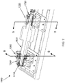
- Auxiliary bearings 1720, 1740 can be included as part of magnetic bearing system 1000 to provide support for rotating shaft 1800 should all the magnetic bearings fail and/or when power is turned off to the magnetic bearings.
- the design and/or location of auxiliary bearings 1720, 1740 can be chosen such that they can withstand the expected loading, have the required operational life, and/or are easily replaced in the field.
- auxiliary bearings 1720, 1740 are shown located outboard of radial bearing 1220 on the NTE and outboard of the thrust bearing 1300 on the TE. Consequently, auxiliary bearings 1720, 1740 can be replaced without the removal of the rotors of radial bearings 1220, 1240 or the rotor of thrust bearing 1300.
- Auxiliary bearings 1720, 1740 can be ball bearings with a radial gap between the inner race and the auxiliary bearing journals.
- the outer race can be mounted in a compliant ring that is in turn mounted in the bearing housing.
- Auxiliary bearings 1720, 1740 can be "soft-mounted" in the compliant rings to reduce the force on auxiliary bearings 1720, 1740 and/or to reduce the propensity for whirl by lowering the stiffness and/or increasing the damping.
- the mechanical properties for the compliant rings can be selected by performing a series of dynamic simulations of the ensuing motion of rotating shaft 1800 after it drops onto auxiliary bearings 1720, 1740 and/or selecting properties that minimize the propensity for whirl.
- Magnetic bearing system 1000 can be designed to compensate for unbalance and/or other static and/or dynamic loads on rotating shaft 1800.
- Magnetic bearings 1220, 1240, 1300 can be designed to operate from approximately -320 °F (77 K) to an elevated temperature of approximately 300 °F (422 K).
- Certain exemplary embodiments of magnetic bearing system 1000 can include a controller 1420, which can be communicatively and/or electrically coupled to the magnetic bearings via a sensor electronics enclosure 1500 and/or a coil cable junction box 1600, so that controller can control the magnetic fields generated by each bearing, and thereby control the relative position of rotating shaft 1800 with respect to the non-rotating portions of rotating machine 1100.
- Certain exemplary embodiments of magnetic bearing system 1000 can provide a magnetic bearing controller 1420 of small size, for example, 12 in x 6 in x 6 in (approximately 30 cm ⁇ 15 cm ⁇ 15 cm). This can provide opportunities to simplify the installation of the magnetic bearing system by mounting magnetic bearing controller 1420 in close proximity to and/or on the machine 1100, such as in an enclosure 1400.
- the controller 1420 can be supplied with DC power and/or an Ethernet cable for communication. If desired, the controller 1420 can be located remotely from machine. Lengths of approximately 50 feet or more (e.g., up to about 100 yards) can be accommodated.
- iron cobalt can be chosen for the magnetic material.
- the laminations for the radial bearings (stators and/or rotors) can be fabricated from Hiperco® 50 or equivalent, which is an iron cobalt alloy with approximately 49% cobalt.
- the thrust bearings can be fabricated from Hiperco® 27 or equivalent, which is an iron cobalt alloy with approximately 27% cobalt ("Hiperco” is a registered trademark of Carpenter Technology of Wyomissing, PA).
- silicon steel can be used for the radial bearings (stators and/or rotors)
- mild steel such as 1018 can be used for the thrust bearing stator
- high strength steel such as 4340 can be used for the thrust disk.
- Certain exemplary embodiments of the magnetic bearing system can provide a multi-channel and/or 3-channel fault tolerant architecture, where a channel is a sub-system that can include a position sensor, a group of radial magnets, a thrust magnet, a controller, and/or the amplifiers of each magnet's respective coil, etc.
- the level of fault tolerance can be N+2, meaning that two channels can fail and the magnetic bearings can continue to operate, although each failure can reduce the load capacity of the magnetic bearings. Even with a failure of one of the channels, the remaining load capacity can be sufficient for continued operation. Note that a simple failure of one sensor or one amplifier or one magnet typically is not sufficient to cause a failure of an entire channel. Thus the typical component failure mode can result in only minor degradation of capacity.
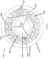
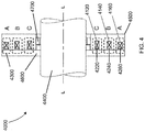
- FIG. 3 and FIG. 4 show cross-sections of an exemplary fault-tolerant radial bearing 3000 and an exemplary thrust bearing 4000, respectively, where the three channels in the figures are represented by the letters A, B, and C.
- each radial bearing stator 3100 can include, for example, nine magnets 3200 grouped into three channels of three magnets apiece.
- Each magnet 3200 is shown with E-shaped poles, although U-shaped poles are also possible.
- the center of the magnets 3200 can be spaced approximately 120° apart about the longitudinal axis L-L (shown in FIG. 4 ) of the rotor so that each single channel can stably support the rotor shaft 3300 by operatively providing, in the context of FIG.
- each magnet 3200 can be magnetically isolated so that the flux in one magnet is not necessarily influenced by the coil currents associated with the other magnets.
- each of magnets 3200 can be separated and/or secured to a non-magnetic housing 3500 with a non-magnetic wedge 3600, as shown.
- the rotor which can include a stack of magnetic laminations that can magnetically interact with the magnets 3200, can be mounted on a hub 3700 which, in turn, can be mounted on shaft 3300.
- a shaft position sensor 3800 can be mounted substantially adjacent to each wedge 3600.
- a longitudinal position of a rotor portion 4600 with respect to a stator portion 4500 of rotating shaft 4400 can be sensed and/or detected via one or more longitudinal and/or thrust sensors 4700.
- FIG. 5 is a block diagram of an exemplary fault tolerant system 5000.
- each channel e.g., A, B, C
- a channel coil routing cable e.g., 5400
- a coil cable junction box 5420 e.g., 5440
- a failure of a channel can reduce the bearing load capacity by approximately one-third.
- the system 5000 can be designed so that with all magnets and channels in operation, the system can have capacity of approximately 120% of the required load capacity. Therefore, even upon a failure of an entire channel of system 5000, the magnetic bearings can nevertheless meet the requirement of 80% of the required load and/or can continue to fully support and/or position the rotating shaft. Even in the unlikely event of failure of two full channels, a single channel typically can be sufficient for 5-axis support of the rotating shaft.
- the magnets within the stator can be magnetically isolated from other magnets by using non-magnetic materials for the housing and wedges. This isolation can ensure that if a coil on a stator pole develops a turn-to-turn short, the flux through that pole can be zero when the amplifier is turned off. If the magnetic flux is not zero due to flux leakage from other magnets, the varying flux can cause an induced voltage on the coil, which might lead to overheating of the coil and/or failure of the entire magnetic bearing.
- eddy current radial position sensors for each radial bearing 5120, 5140 and/or three eddy current position sensors for the thrust bearing 5200.
- the outputs of the sensors can be routed via sensor electronics enclosure 5620 and sensor signal cables 5640 and, for redundancy, input to all the controllers 5320, 5340, and 5360, regardless of the channel with which the sensor is associated, and/or a controller other than the controller associated with the channel. Therefore, the failure of any sensor can be detected and it need cause no degradation in the performance of the system.
- any of the components shown within box 5900 can be machine mounted.
- controllers 5320, 5340, and 5360 can be located within a single enclosure 5800, which can include a sensor routing termination 5820 and a coil wire routing termination 5840. Each controller can be supplied with two sources 5720, 5740 of 440 V AC , three-phase power. In the event of failure of one source of power, system 5000 can continue to operate without interruption.
- the thrust rotor can be a disk (sometimes called a "runner") that can be secured to the shaft. Because the thrust disk can be "captive" between the two thrust bearing stators, assembly of the machine can require the shaft first to be installed without the thrust disk followed by the installation of the inboard thrust stator followed by the installation of the thrust disk followed by the installation of the outboard thrust stator. To dissemble the machine, it can be necessary to remove the outboard thrust disk followed by removal of the thrust disk followed by removal of the inboard thrust stator followed by removal of the shaft.
- this thrust disk after the shaft is installed can be difficult because the disk is often secured to the shaft with an interference fit.
- the interference fit can be necessary to ensure that the disk remains secured to the shaft when the bore of the thrust disk grows radially due to centrifugal forces that can be developed while rotating.
- the thrust disk for a large machine also can be large (diameter greater than 20 inch, approximately 51 cm) and heavy (more than 100 lb, about 45 kg).
- the combination of interference fit, size, and weight of the thrust disk can make it difficult and/or costly to install and/or remove the thrust disk once the shaft is installed in the machine.
- Another approach can be to design a thrust stator that is horizontally split so that the machine can be assembled and/or disassembled with the thrust disk secured on the shaft. This also can permit removal of all magnetic bearings from the machine without removing the shaft.
- the challenge can be to design a thrust stator that can be split in half (or into 3, 4, or more sectors) and also produce a circumferentially uniform (axi-symmetric) field at the pole faces when the two halves (or the multiple sectors) are assembled in the machine.
- the axi-symmetric field can be required to minimize magnetic losses in the thrust rotor that can occur as the shaft is rotated.
- FIG. 6 and FIG. 7 show isometric views of the front and back of an exemplary thrust stator 6000 when the two sectors and/or halves 6100 and 6200 are together. Shown is a version of the thrust stator with 5 poles, which can be achieved with coils inserted into 4 circumferential slots that are formed in the stator and bounded by semi-disc 6600. One continuous coil can fill the inner two adjacent slots and/or another continuous coil 6300 can fill the outer two adjacent slots. The slots therefore can be arranged as adjacent slot pairs.
- FIG. 8 shows a front view of an exemplary thrust stator 8000 that is divided into two semi-circumferential sectors, shown as a top half 8010 and a bottom half 8020.
- FIG. 9 shows a cross-sectional view of thrust stator 8000 taken at section A-A. Note how coils 8100 are separated by poles 8200, which are coupled to and/or integral to disc 8300.
- FIG. 10 shows a magnified view of detail B of FIG. 9 , and shows the alternating and opposite polarity of several coils 8100 and poles 8200.
- FIG. 11 and FIG. 12 show isometric views of a half or semi-circumferential sector of an exemplary thrust stator 11000, including semi-circumferential thrust poles 11100, semi-circumferential coils 11200, and U-shaped bends 11300.
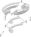
- FIG. 13 shows an exploded view of an exemplary thrust stator 13000, including semi-circumferential poles 13100, semi-circumferential coils 13200 (formed from a pair of substantially parallel semi-toroidal portions coupled by opposing U-shaped bends 13300), semi-discs 13400, and 4 substantially parallel curved slots 13500.
- the semi-disc 13400 of each sector extends within a plane that is substantially perpendicular to the longitudinal axis of rotation.
- the semi-toroidal portions of coils 13200 extend in the same plane, but that the U-shaped bends 13300 extend perpendicularly to that plane, and in a plane substantially parallel to the longitudinal axis.
- the coil pairs (where a "pair” in this context is a continuous closed-loop coil from one sector of the thrust stator that is electrically coupled to a corresponding coil (not shown) from one or more other sectors (not shown)) can be connected to independent amplifiers in independent controllers such that thrust bearing can continue to function with the failure of a channel of control. It is possible to extend the number of coils and poles to accommodate more channels of redundancy. For instance, three channels of redundancy can be achieved with a stator that has 3 coils in 6 slots with 7 poles.
- FIG. 14 is a block diagram of an exemplary embodiment of an information device 14000, which in certain operative embodiments can comprise, for example, controller 1420 of FIG. 1 and/or controller 5320, 5340, and/or 5360 of FIG. 5 .
- Information device 14000 can comprise any of numerous transform circuits, which can be formed via any of numerous communicatively-, electrically-, magnetically-, optically-, fluidically-, and/or mechanically-coupled physical components, such as for example, one or more network interfaces 14100, one or more processors 14200, one or more memories 14300 containing instructions 14400, one or more input/output (I/O) devices 14500, and/or one or more user interfaces 14600 coupled to I/O device 14500, etc.
- I/O input/output
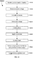
- FIG. 15 is a flowchart of an exemplary embodiment of a method 15000, which can include any combination of the following activities.
- a controller can receive a sensed, detected, and/or transmitted indication of a position of a rotating shaft and/or a sensed, detected, and/or transmitted indication of a stator magnetic bearing-generated vibration.
- the controller can detect, recognize, and/or determine that an applied coil voltage exceeds a coil amplifier voltage capability.
- the controller can estimate a resistance of a coil.
- the controller can determine a voltage to be delivered to a coil.
- the controller can correct a phase of a flux of a magnet corresponding to a coil.
- the controller can adaptively apply sufficient corrections to a received position signal and/or a magnetic bearing force of said shaft to attenuate a stator magnetic bearing-generated vibration, such as a vibration that is transmitted synchronously with a rotational frequency of said shaft and/or one or more harmonics of said rotational frequency.
- At activity 15700 at least two magnetic radial bearings can magnetically levitate a rotating shaft, each of the magnetic radial bearings comprising at least three stator magnet groups, each of the stator magnet groups comprising at least three stator magnets that are substantially uniformly distributed around a longitudinal axis of the rotating shaft, no pair of the at least three stator magnets separated by 180 degrees measured about the longitudinal axis, each of the stator magnet groups operatively adapted to fully support the rotating shaft independently of each other of the stator magnet groups.
- At activity 15800 via a thrust stator of a magnetic bearing, the thrust stator adapted to be split into sectors so that a shaft of a machine can be removed from the magnetic bearing, producing an axi-symmetric field at each pole face of the thrust stator when the sectors are operatively assembled in the machine.
- at least one magnetic thrust bearing can longitudinally position the shaft, the magnetic thrust bearing comprising at least three isolated thrust coils, electromagnets, and/or magnets.
- FIG. 16 is a block diagram of an exemplary control process 16000.
- a controller can utilize either a single-input/single output (SISO) architecture or a multiple-input/multiple output (MIMO) architecture, either which that can be modified to improve dynamic performance and/or adaptive noise cancellation.
- SISO single-input/single output
- MIMO multiple-input/multiple output
- Certain exemplary embodiments of the blocks in FIG. 16 can be described as follows, and/or can be implemented as software, firmware, and/or hardware modules and/or as one or more processes.
- the compensation module can determine what level of force should be applied based on the position error.
- the simplest of such approaches can be a PID process, which can be thought of as first-order transfer function with an integrator term. We generalize this compensation process to be an eighth-order transfer function plus an integrator term.
- the gain and phase of the compensator can be shaped with eight zeroes and eight poles in an arbitrary manner, including first-order leads, first-order lags, notches, and/or second-order filters. The selection of the location (frequency and/or damping ratio) of these zeroes and/or poles can optimize the performance of the bearing, and/or can be easily accomplished with selection of input parameters via a user interface.
- this optimization process can include time to properly characterize the rotating assembly, identify structural resonances in the static structure, and/or stabilize some and/or all of the identified system modes.
- the input parameters for the compensation module can be chosen using well-known techniques described in various references, such as those described in Mushi, Lin, Allaire, "Design, Construction and Modeling of a Flexible Rotor Active Magnetic Bearing Test Rig", Proceedings of ASME Turbo Expo 2010: Power for Land, Sea and Air GT2010, paper GT2010-23619, presented June 14-18, 2010, Glasgow, UK .
- Flux estimation module 16200 To improve the performance of the magnetic bearings, the magnetic flux in the air gap can be estimated using a module and/or process that can include the effects of coil inductance, coil resistance, and/or leakage flux. Because flux can be more closely related to the force in the bearing than current, the performance of the magnetic bearing can be improved, especially at high frequencies and/or high loadings, in which case non-linear effects such as eddy currents and/or magnetic saturation can degrade the performance. This process can have the force command from the compensation process as an input. It then can calculate the voltage required to achieve this level of force.
- Dynamic force compensation module 16300 Under conditions of high dynamic force, the voltage output of the amplifier can be insufficient to "slew" the force at the required rate. This can be referred to as voltage saturation. Voltage saturation also can be caused by excessive high frequency gain and/or by sensor noise. When the amplifier is in a state of voltage saturation, the magnetic bearing can go unstable due to phase lag of the force produced by the magnetic bearing. With our dynamic force compensation module and/or process, this phase lag can be greatly reduced or eliminated by automatically reducing the gain, and/or the bearing can remain very stable, even under conditions of high dynamic force. This can create a dramatic improvement of performance and/or stability of the system. This feature can be important in situations where there is a potential of high dynamic loading.
- the input for this module and/or process can be the desired voltage calculated by the flux estimation model.
- the output can be the voltage after it is corrected for voltage saturation effects.
- Coil Resistance module 16400 The voltage and current from each amplifier constantly can be monitored and/or an estimate for the resistance to the coil continuously can be updated.
- This resistance value can serve two purposes. For one, it can be used in the flux estimation process to estimate the flux in the coil. Secondly, it can be used to continuously monitor the health of the coil by detecting variations in the resistance.
- the amplifiers used in the controllers can be pulse wave modulated (PWM) amplifiers in which the output voltage can be controlled by varying the width of the voltage pulse sent to the coils. There need be no inner loop to control the current and there need be no requirement to "flux tune" the amplifiers.
- PWM pulse wave modulated
- the controller can include two enhancements that can use adaptive cancellation modules and/or processes.
- the "Magnetic Balance” feature can minimize synchronous (once-per-revolution) vibration of the shaft by adaptively injecting a synchronous force correction.
- the "Inertial Balance” feature adaptively can minimize synchronous force in the bearing by adaptively injecting synchronous position correction (the Magnetic Balance and Inertial Balance typically are not simultaneously applied).
- the Inertial Balance can be extended to reduce acoustic noise at the synchronous frequency and/or for harmonics of the synchronous frequency. For a linear system, the cancellation at one frequency can be independent of the cancellation at other frequencies, and therefore the processes can be extended to multiple harmonic frequencies.
- the controller can utilize SISO because it has proven to be a simple and robust technique, as which has been described in various publications, such as Mushi, Lin, Allaire, "Design, Construction and Modeling of a Flexible Rotor Active Magnetic Bearing Test Rig", Proceedings of ASME Turbo Expo 2010: Power for Land, Sea and Air GT2010, paper GT2010-23619, presented June 14-18, 2010, Glasgow, UK .
- the process can be extended to be a multiple input - multiple output (MIMO) controller in which states of the system are independently observed and controlled.
- MIMO multiple input - multiple output
- MIMO controllers can be successfully used, for example, for systems in which the two rigid body modes of the system vary widely in frequency such that it is difficult to devise a compensation process that adequately stabilizes both modes (decomposition of the displacement into more than two modes can require sensors located at additional planes along the length of the shaft).
- the rigid body displacement of the shaft can be decomposed into the superposition of the two rigid body modes and then the modes can be independently controlled.
- An exemplary way in which noise can be attenuated can be the adaptive control of transmitted forces from the bearings into the structure.
- the adaptive noise cancellation process can minimize the transmitted force at harmonic frequencies of the rotational frequency.
- An exemplary embodiment of such a process 17000 and/or module is shown in FIG. 17 .
- a once-per-revolution pulse can be tracked with phase-locked loop (PLL) process 17100.
- the output of the PLL process 17100 can be a set of sine and cosine signals at integral multiples of the frequency of the once-per-rev signal. For example, if up to the ninth harmonic is to be attenuated, then nine pairs of sine and cosine signals can be utilized.
- these sine and cosine signals then can be used to compute the Fourier coefficients of the position signal.
- the Fourier coefficients of the position signal A i , B i can be minimized by adding a harmonic correction to the position signal, and/or adaptively adjusting the Fourier coefficients of the harmonic correction ⁇ i , ⁇ i until A i and B i are small.
- Certain exemplary embodiments can provide a machine comprising a magnetic bearing thrust stator, comprising:
- Certain exemplary embodiments can provide a thrust stator of a magnetic bearing, the thrust stator adapted to be split into sectors so that a shaft of a machine can be removed from the magnetic bearing, the thrust stator operatively adapted to produce an axi-symmetric field at each pole face of the thrust stator when the sectors are assembled in the machine.
- Certain exemplary embodiments can provide a method, comprising, via a thrust stator of a magnetic bearing, the thrust stator adapted to be split into sectors so that a shaft of a machine can be removed from the magnetic bearing, producing an axi-symmetric field at each pole face of the thrust stator when the sectors are operatively assembled in the machine.
- any two or more described substances can be mixed, combined, reacted, separated, and/or segregated;
- any described characteristics, functions, activities, substances, and/or structural elements can be integrated, segregated, and/or duplicated;
- any described activity can be performed manually, semi-automatically, and/or automatically;
- any described activity can be repeated, any activity can be performed by multiple entities, and/or any activity can be performed in multiple jurisdictions;
- any described characteristic, function, activity, substance, and/or structural element can be specifically excluded, the sequence of activities can vary, and/or the interrelationship of structural elements can vary.
- drawing element number is exemplary and nonlimiting on claim scope.
Landscapes
- Engineering & Computer Science (AREA)
- General Engineering & Computer Science (AREA)
- Mechanical Engineering (AREA)
- Power Engineering (AREA)
- Magnetic Bearings And Hydrostatic Bearings (AREA)
Description
- This application claims priority to pending
U.S. Provisional Patent Application 61/357,564, filed 23 June 2010 - Document
US 2003/038553 discloses a turbo-generator machine for producing a supply of cooled air and a supply of electric power having a permanent magnet generator fixed to a shaft, which is driven by a turbine rotor, the turbine serving to expand air which is supplied thereto. Magnetic bearings support the shaft radially for rotation about a precisely established axis while a magnetic thrust bearing keeps the shaft in a precisely fixed axial position. Power for the magnetic bearings is supplied by the turbo-generator during operation. - Document
US 5,455,472 discloses a magnetic bearing assembly, which provides for correction of shaft deflection, or "bowing", during rotation of the shaft. The assembly comprises two stator rings in spaced relation to each other, and each stator ring comprises a plurality of stator sections which are independently activated. When the shaft "bows", sensors detect the deflection and independently activate the various stator sections producing a force couple which acts on the rotor to produce a bending moment in the shaft which tends to counteract the "bowing". - Document
US 5,705,869 discloses an axial magnetic thrust bearing stator including a plurality of laminated cores. Each of the cores is magnetically conductive, situated in a common plane, and symmetrically situated about a center of rotation. - Document
US 4,920,291 discloses an electromagnetic axial thrust bearing comprising a rotating member, at least one stationary member and a winding for generating a magneto motive force associated with the stationary member. The stationary member is comprised of a solid ferromagnetic material having at least one arc-shaped groove substantially concentric with the turning axis of the rotating member. The groove is lined with laminates of a ferromagnetic material. The winding is laid into the lined groove of the stationary member. - A wide variety of potential practical and useful embodiments will be more readily understood through the following detailed description of certain exemplary embodiments, with reference to the accompanying exemplary drawings in which:
-
FIG. 1 is a perspective view of an exemplary embodiment of a system; -
FIG. 2 is a perspective cut-away view of an exemplary embodiment of a rotating machine; -
FIG. 3 is a cross-sectional view, viewed in the direction of the arrowheads attached to line A-A ofFIG. 2 , of an exemplary radial bearing; -
FIG. 4 is a cross-sectional view, viewed in the direction of the arrowheads attached to line B-B ofFIG. 2 , of an exemplary thrust bearing; -
FIG. 5 is a block diagram of an exemplary fault tolerant system; -
FIG. 6 is a perspective view of an exemplary thrust stator; -
FIG. 7 is a perspective view of an exemplary thrust stator; -
FIG. 8 is a perspective view of an exemplary thrust stator; -
FIG. 9 is a cross-sectional view, viewed in the direction of the arrowheads attached to line A-A ofFIG. 8 , of an exemplary thrust stator; -
FIG. 10 is a magnified view of detail B ofFIG. 9 , of an exemplary thrust stator; -
FIG. 11 is a perspective view of an exemplary thrust stator sector; -
FIG. 12 is a perspective view of an exemplary thrust stator sector; -
FIG. 13 is an exploded view of an exemplary thrust stator; -
FIG. 14 is a block diagram of an exemplary embodiment of an information device; -
FIG. 15 is a flowchart of an exemplary embodiment of a method; -
FIG. 16 is a block diagram of an exemplary control process; and -
FIG. 17 is a block diagram of an exemplary adaptive cancellation process. - Certain exemplary embodiments can provide a system, machine, device, manufacture, circuit, composition of matter, and/or user interface adapted for and/or resulting from, and/or a method and/or machine-readable medium comprising machine-implementable instructions for, activities that can comprise and/or relate to: via a thrust stator of a magnetic bearing, the thrust stator adapted to be split into sectors so that a shaft of a machine can be removed from the magnetic bearing, producing an axi-symmetric field at each pole face of the thrust stator when the sectors are operatively assembled in the machine; and/or a magnetic bearing thrust stator, comprising a plurality of stator sectors, each of the stator sectors comprising a semi-circumferentially slotted stator portion comprising a plurality of semi-circumferential poles and a first coil portion shaped to fit substantially within the semi-circumferentially slotted stator portion.
-
FIG. 1 shows a perspective view of an exemplary magnetic bearing system 1000, which can include a rotatingmachine 1100 supported via magnetic bearings. Examples ofrotating machines 1100 that can benefit from magnetic bearings can include compressors, blowers, pumps, turbines, motors, and generators. Certain rotating machines can include adrive motor 1200 for powering the rotating machine. As shown inFIG. 1 andFIG. 2 , magnetic bearing system 1000 can include tworadial bearings shaft 1800 and/or maintaining a relative position of that shaft along lateral directions (perpendicular to the longitudinal axis of the shaft) and/or a thrust bearing 1300 for supporting rotatingshaft 1800 and/or maintaining a relative position of that shaft along the longitudinal direction (parallel to the longitudinal axis of the shaft). Together, the three magnetic bearings (1220, 1240, 1300) can provide position and/or support along 5 axes of motion and/or can provide little resistance to rotation of the shaft. One radial bearing 1220 can be located at the non-thrust end (NTE) of themachine 1100. Radial bearing 1240 and thrust bearing 1300 can be located together at the thrust-end (TE) of the machine. At the TE, thrust bearing 1300 can located inboard of the radial bearing 1240 to maximize the accessibility of components without removing the thrust disk, thereby improving maintainability and/or serviceability. Controlling the magnetic fields generated by thebearings magnetic bearing controller 1420, which can provide sensor conditioning, digital processing, and/or power amplification. - Each magnetic bearing can include a non-rotating stator, which can be secured to the frame of the machine, and a rotating rotor, which can be secured to the rotating shaft. During operation, attractive magnetic forces can be developed between the stator and rotor. The forces can support and/or position the rotating shaft without the rotor contacting the stator, such that the stator is positioned adjacent to, but displaced from, the rotor.
-
Auxiliary bearings shaft 1800 should all the magnetic bearings fail and/or when power is turned off to the magnetic bearings. The design and/or location ofauxiliary bearings FIG. 2 ,auxiliary bearings auxiliary bearings radial bearings -
Auxiliary bearings Auxiliary bearings auxiliary bearings shaft 1800 after it drops ontoauxiliary bearings - Magnetic bearing system 1000 can be designed to compensate for unbalance and/or other static and/or dynamic loads on rotating
shaft 1800.Magnetic bearings - Certain exemplary embodiments of magnetic bearing system 1000 can include a
controller 1420, which can be communicatively and/or electrically coupled to the magnetic bearings via asensor electronics enclosure 1500 and/or a coilcable junction box 1600, so that controller can control the magnetic fields generated by each bearing, and thereby control the relative position of rotatingshaft 1800 with respect to the non-rotating portions ofrotating machine 1100. Certain exemplary embodiments of magnetic bearing system 1000 can provide amagnetic bearing controller 1420 of small size, for example, 12 in x 6 in x 6 in (approximately 30 cm ∗ 15 cm ∗ 15 cm). This can provide opportunities to simplify the installation of the magnetic bearing system by mountingmagnetic bearing controller 1420 in close proximity to and/or on themachine 1100, such as in anenclosure 1400. This greatly can reduce the cabling requirements and/or the time to perform the initial calibration and/or initialization of the magnetic bearing system. In such a system, thecontroller 1420 can be supplied with DC power and/or an Ethernet cable for communication. If desired, thecontroller 1420 can be located remotely from machine. Lengths of approximately 50 feet or more (e.g., up to about 100 yards) can be accommodated. - To minimize the size of the magnetic radial and/or thrust bearings, iron cobalt can be chosen for the magnetic material. The laminations for the radial bearings (stators and/or rotors) can be fabricated from
Hiperco® 50 or equivalent, which is an iron cobalt alloy with approximately 49% cobalt. The thrust bearings can be fabricated from Hiperco® 27 or equivalent, which is an iron cobalt alloy with approximately 27% cobalt ("Hiperco" is a registered trademark of Carpenter Technology of Wyomissing, PA). To reduce the cost, silicon steel can be used for the radial bearings (stators and/or rotors), mild steel such as 1018 can be used for the thrust bearing stator, and/or high strength steel such as 4340 can be used for the thrust disk. - Certain exemplary embodiments of the magnetic bearing system can provide a multi-channel and/or 3-channel fault tolerant architecture, where a channel is a sub-system that can include a position sensor, a group of radial magnets, a thrust magnet, a controller, and/or the amplifiers of each magnet's respective coil, etc. The level of fault tolerance can be N+2, meaning that two channels can fail and the magnetic bearings can continue to operate, although each failure can reduce the load capacity of the magnetic bearings. Even with a failure of one of the channels, the remaining load capacity can be sufficient for continued operation. Note that a simple failure of one sensor or one amplifier or one magnet typically is not sufficient to cause a failure of an entire channel. Thus the typical component failure mode can result in only minor degradation of capacity.
-
FIG. 3 andFIG. 4 show cross-sections of an exemplary fault-tolerant radial bearing 3000 and anexemplary thrust bearing 4000, respectively, where the three channels in the figures are represented by the letters A, B, and C. As shown inFIG. 3 , eachradial bearing stator 3100 can include, for example, ninemagnets 3200 grouped into three channels of three magnets apiece. Eachmagnet 3200 is shown with E-shaped poles, although U-shaped poles are also possible. For each channel, the center of themagnets 3200 can be spaced approximately 120° apart about the longitudinal axis L-L (shown inFIG. 4 ) of the rotor so that each single channel can stably support therotor shaft 3300 by operatively providing, in the context ofFIG. 3 andFIG. 4 , a vertical force component and/or, as needed, horizontal and/or longitudinal force components, torotor shaft 3300. The magnetic flux generated by eachmagnet 3200 can be controlled via a current applied to acoil 3400 associated with that magnet, the current flowing through that coil inducing a magnetic field in the air gap between the rotor and stator. As shown by theflux path 3250, eachmagnet 3200 can be magnetically isolated so that the flux in one magnet is not necessarily influenced by the coil currents associated with the other magnets. To facilitate this magnetic isolation and/or to constrain motion of the magnets, each ofmagnets 3200 can be separated and/or secured to anon-magnetic housing 3500 with anon-magnetic wedge 3600, as shown. The rotor, which can include a stack of magnetic laminations that can magnetically interact with themagnets 3200, can be mounted on ahub 3700 which, in turn, can be mounted onshaft 3300. Ashaft position sensor 3800 can be mounted substantially adjacent to eachwedge 3600. - As shown in
FIG. 4 , at anexemplary thrust bearing 4000, a longitudinal position of arotor portion 4600 with respect to astator portion 4500 ofrotating shaft 4400 can be sensed and/or detected via one or more longitudinal and/or thrustsensors 4700. To manage that longitudinal position, there can be threeisolated thrust magnets corresponding coil corresponding flux path 4300 that can magnetically interact with the steel of a thrust disk to influence a longitudinal position ofrotating shaft 4400. -
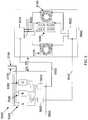
FIG. 5 is a block diagram of an exemplary faulttolerant system 5000. As shown inFIG. 5 , to form a complete, distinct, and/or independent magnetic bearing control system, each channel (e.g., A, B, C) can include three magnetic sectors (e.g., A, A, and A; or B, B, and B; or C, C, and C) of eachradial bearing thrust bearing 5200, a digital controller (e.g., 5320, 5340, or 5360), and/or amplifiers (located in each controller) for the coil of each magnet, each amplifier communicatively and/or electrically connected from a coilwire routing termination 5840 in thecontroller enclosure 5800 via a channel coil routing cable (e.g., 5400) to a coilcable junction box 5420 and then via a coil routing cable (e.g., 5440) to its respective coil. A failure of a channel can reduce the bearing load capacity by approximately one-third. However, thesystem 5000 can be designed so that with all magnets and channels in operation, the system can have capacity of approximately 120% of the required load capacity. Therefore, even upon a failure of an entire channel ofsystem 5000, the magnetic bearings can nevertheless meet the requirement of 80% of the required load and/or can continue to fully support and/or position the rotating shaft. Even in the unlikely event of failure of two full channels, a single channel typically can be sufficient for 5-axis support of the rotating shaft. - So the magnetic bearing can continue to operate with a failed coil in the stator, the magnets within the stator can be magnetically isolated from other magnets by using non-magnetic materials for the housing and wedges. This isolation can ensure that if a coil on a stator pole develops a turn-to-turn short, the flux through that pole can be zero when the amplifier is turned off. If the magnetic flux is not zero due to flux leakage from other magnets, the varying flux can cause an induced voltage on the coil, which might lead to overheating of the coil and/or failure of the entire magnetic bearing.
- There can be nine eddy current radial position sensors for each
radial bearing thrust bearing 5200. The outputs of the sensors can be routed viasensor electronics enclosure 5620 andsensor signal cables 5640 and, for redundancy, input to all thecontrollers box 5900 can be machine mounted. - Any of
controllers single enclosure 5800, which can include asensor routing termination 5820 and a coilwire routing termination 5840. Each controller can be supplied with twosources system 5000 can continue to operate without interruption. - The approach to fault tolerance described herein can provide a redundant, highly robust system.
- Referring to
FIG. 1 andFIG. 2 , to support the shaft along the longitudinal axes in both directions, it sometimes can be helpful to incorporate two thrust bearing stators, one on each side of the thrust rotor. The thrust rotor can be a disk (sometimes called a "runner") that can be secured to the shaft. Because the thrust disk can be "captive" between the two thrust bearing stators, assembly of the machine can require the shaft first to be installed without the thrust disk followed by the installation of the inboard thrust stator followed by the installation of the thrust disk followed by the installation of the outboard thrust stator. To dissemble the machine, it can be necessary to remove the outboard thrust disk followed by removal of the thrust disk followed by removal of the inboard thrust stator followed by removal of the shaft. - The installation and removal of this thrust disk after the shaft is installed can be difficult because the disk is often secured to the shaft with an interference fit. The interference fit can be necessary to ensure that the disk remains secured to the shaft when the bore of the thrust disk grows radially due to centrifugal forces that can be developed while rotating. The thrust disk for a large machine also can be large (diameter greater than 20 inch, approximately 51 cm) and heavy (more than 100 lb, about 45 kg). The combination of interference fit, size, and weight of the thrust disk can make it difficult and/or costly to install and/or remove the thrust disk once the shaft is installed in the machine.
- Another approach can be to design a thrust stator that is horizontally split so that the machine can be assembled and/or disassembled with the thrust disk secured on the shaft. This also can permit removal of all magnetic bearings from the machine without removing the shaft. The challenge can be to design a thrust stator that can be split in half (or into 3, 4, or more sectors) and also produce a circumferentially uniform (axi-symmetric) field at the pole faces when the two halves (or the multiple sectors) are assembled in the machine. The axi-symmetric field can be required to minimize magnetic losses in the thrust rotor that can occur as the shaft is rotated.
-
FIG. 6 and FIG. 7 show isometric views of the front and back of anexemplary thrust stator 6000 when the two sectors and/orhalves continuous coil 6300 can fill the outer two adjacent slots. The slots therefore can be arranged as adjacent slot pairs. The coil can follow one circumferential slot in one direction (e.g., clockwise) and/or then can connect through a U-shaped section of the coil to the adjacent circumferential slot and/or then can follow this circumferential slot in the other direction (e.g., counter clockwise). BecauseU-shaped bend 6500 can be formed along a plane that can be perpendicular to the circumferential path of the coil, eachpole 6400 of the thrust stator can be circumferential without interruption. The poles of the stator can be of alternate magnetic polarity as one proceeds radially outward. -
FIG. 8 shows a front view of anexemplary thrust stator 8000 that is divided into two semi-circumferential sectors, shown as atop half 8010 and abottom half 8020.FIG. 9 shows a cross-sectional view ofthrust stator 8000 taken at section A-A. Note howcoils 8100 are separated bypoles 8200, which are coupled to and/or integral todisc 8300.FIG. 10 shows a magnified view of detail B ofFIG. 9 , and shows the alternating and opposite polarity ofseveral coils 8100 andpoles 8200. -
FIG. 11 and FIG. 12 show isometric views of a half or semi-circumferential sector of anexemplary thrust stator 11000, includingsemi-circumferential thrust poles 11100,semi-circumferential coils 11200, and U-shaped bends 11300. -
FIG. 13 shows an exploded view of anexemplary thrust stator 13000, includingsemi-circumferential poles 13100, semi-circumferential coils 13200 (formed from a pair of substantially parallel semi-toroidal portions coupled by opposing U-shaped bends 13300),semi-discs 13400, and 4 substantially parallelcurved slots 13500. Note that thesemi-disc 13400 of each sector extends within a plane that is substantially perpendicular to the longitudinal axis of rotation. Note also that the semi-toroidal portions ofcoils 13200 extend in the same plane, but that theU-shaped bends 13300 extend perpendicularly to that plane, and in a plane substantially parallel to the longitudinal axis. For redundancy, the coil pairs (where a "pair" in this context is a continuous closed-loop coil from one sector of the thrust stator that is electrically coupled to a corresponding coil (not shown) from one or more other sectors (not shown)) can be connected to independent amplifiers in independent controllers such that thrust bearing can continue to function with the failure of a channel of control. It is possible to extend the number of coils and poles to accommodate more channels of redundancy. For instance, three channels of redundancy can be achieved with a stator that has 3 coils in 6 slots with 7 poles. - Thus, certain exemplary embodiments can provide a coil shape with a U-bend in perpendicular plane that can allow the stator halves (and/or sectors) to connect so that the poles of each stator half (and/or sector) can touch without substantial interruption and/or can remain electrically coupled in series.
-
FIG. 14 is a block diagram of an exemplary embodiment of aninformation device 14000, which in certain operative embodiments can comprise, for example,controller 1420 ofFIG. 1 and/orcontroller FIG. 5 .Information device 14000 can comprise any of numerous transform circuits, which can be formed via any of numerous communicatively-, electrically-, magnetically-, optically-, fluidically-, and/or mechanically-coupled physical components, such as for example, one ormore network interfaces 14100, one ormore processors 14200, one ormore memories 14300 containinginstructions 14400, one or more input/output (I/O)devices 14500, and/or one or more user interfaces 14600 coupled to I/O device 14500, etc. - In certain exemplary embodiments, via one or more user interfaces 14600, such as a graphical user interface, a user can view a rendering of information related to researching, designing, modeling, creating, developing, building, manufacturing, operating, maintaining, storing, marketing, selling, delivering, selecting, specifying, requesting, ordering, receiving, returning, rating, and/or recommending any of the products, services, methods, user interfaces, and/or information described herein.
-
FIG. 15 is a flowchart of an exemplary embodiment of amethod 15000, which can include any combination of the following activities. Atactivity 15100, a controller can receive a sensed, detected, and/or transmitted indication of a position of a rotating shaft and/or a sensed, detected, and/or transmitted indication of a stator magnetic bearing-generated vibration. Atactivity 15200, the controller can detect, recognize, and/or determine that an applied coil voltage exceeds a coil amplifier voltage capability. Atactivity 15300, the controller can estimate a resistance of a coil. Atactivity 15400, the controller can determine a voltage to be delivered to a coil. Atactivity 15500, the controller can correct a phase of a flux of a magnet corresponding to a coil. Atactivity 15600, the controller can adaptively apply sufficient corrections to a received position signal and/or a magnetic bearing force of said shaft to attenuate a stator magnetic bearing-generated vibration, such as a vibration that is transmitted synchronously with a rotational frequency of said shaft and/or one or more harmonics of said rotational frequency. Atactivity 15700, at least two magnetic radial bearings can magnetically levitate a rotating shaft, each of the magnetic radial bearings comprising at least three stator magnet groups, each of the stator magnet groups comprising at least three stator magnets that are substantially uniformly distributed around a longitudinal axis of the rotating shaft, no pair of the at least three stator magnets separated by 180 degrees measured about the longitudinal axis, each of the stator magnet groups operatively adapted to fully support the rotating shaft independently of each other of the stator magnet groups. Atactivity 15800, via a thrust stator of a magnetic bearing, the thrust stator adapted to be split into sectors so that a shaft of a machine can be removed from the magnetic bearing, producing an axi-symmetric field at each pole face of the thrust stator when the sectors are operatively assembled in the machine. Atactivity 15900, at least one magnetic thrust bearing can longitudinally position the shaft, the magnetic thrust bearing comprising at least three isolated thrust coils, electromagnets, and/or magnets. -
FIG. 16 is a block diagram of anexemplary control process 16000. A controller can utilize either a single-input/single output (SISO) architecture or a multiple-input/multiple output (MIMO) architecture, either which that can be modified to improve dynamic performance and/or adaptive noise cancellation. Certain exemplary embodiments of the blocks inFIG. 16 can be described as follows, and/or can be implemented as software, firmware, and/or hardware modules and/or as one or more processes. -
Compensation module 16100. The compensation module can determine what level of force should be applied based on the position error. The simplest of such approaches can be a PID process, which can be thought of as first-order transfer function with an integrator term. We generalize this compensation process to be an eighth-order transfer function plus an integrator term. As such, the gain and phase of the compensator can be shaped with eight zeroes and eight poles in an arbitrary manner, including first-order leads, first-order lags, notches, and/or second-order filters. The selection of the location (frequency and/or damping ratio) of these zeroes and/or poles can optimize the performance of the bearing, and/or can be easily accomplished with selection of input parameters via a user interface. This sometimes can be referred to as "tuning" the bearing. Typically, this optimization process can include time to properly characterize the rotating assembly, identify structural resonances in the static structure, and/or stabilize some and/or all of the identified system modes. The input parameters for the compensation module can be chosen using well-known techniques described in various references, such as those described in Mushi, Lin, Allaire, "Design, Construction and Modeling of a Flexible Rotor Active Magnetic Bearing Test Rig", Proceedings of ASME Turbo Expo 2010: Power for Land, Sea and Air GT2010, paper GT2010-23619, presented June 14-18, 2010, Glasgow, UK. -
Flux estimation module 16200. To improve the performance of the magnetic bearings, the magnetic flux in the air gap can be estimated using a module and/or process that can include the effects of coil inductance, coil resistance, and/or leakage flux. Because flux can be more closely related to the force in the bearing than current, the performance of the magnetic bearing can be improved, especially at high frequencies and/or high loadings, in which case non-linear effects such as eddy currents and/or magnetic saturation can degrade the performance. This process can have the force command from the compensation process as an input. It then can calculate the voltage required to achieve this level of force. - Dynamic
force compensation module 16300. Under conditions of high dynamic force, the voltage output of the amplifier can be insufficient to "slew" the force at the required rate. This can be referred to as voltage saturation. Voltage saturation also can be caused by excessive high frequency gain and/or by sensor noise. When the amplifier is in a state of voltage saturation, the magnetic bearing can go unstable due to phase lag of the force produced by the magnetic bearing. With our dynamic force compensation module and/or process, this phase lag can be greatly reduced or eliminated by automatically reducing the gain, and/or the bearing can remain very stable, even under conditions of high dynamic force. This can create a dramatic improvement of performance and/or stability of the system. This feature can be important in situations where there is a potential of high dynamic loading. The input for this module and/or process can be the desired voltage calculated by the flux estimation model. The output can be the voltage after it is corrected for voltage saturation effects. -
Coil Resistance module 16400. The voltage and current from each amplifier constantly can be monitored and/or an estimate for the resistance to the coil continuously can be updated. This resistance value can serve two purposes. For one, it can be used in the flux estimation process to estimate the flux in the coil. Secondly, it can be used to continuously monitor the health of the coil by detecting variations in the resistance. - Voltage Amplifier 16500. The amplifiers used in the controllers can be pulse wave modulated (PWM) amplifiers in which the output voltage can be controlled by varying the width of the voltage pulse sent to the coils. There need be no inner loop to control the current and there need be no requirement to "flux tune" the amplifiers.
- Adaptive
Noise Cancellation module 16600. The controller can include two enhancements that can use adaptive cancellation modules and/or processes. The "Magnetic Balance" feature can minimize synchronous (once-per-revolution) vibration of the shaft by adaptively injecting a synchronous force correction. By contrast, the "Inertial Balance" feature adaptively can minimize synchronous force in the bearing by adaptively injecting synchronous position correction (the Magnetic Balance and Inertial Balance typically are not simultaneously applied). The Inertial Balance can be extended to reduce acoustic noise at the synchronous frequency and/or for harmonics of the synchronous frequency. For a linear system, the cancellation at one frequency can be independent of the cancellation at other frequencies, and therefore the processes can be extended to multiple harmonic frequencies. - The controller can utilize SISO because it has proven to be a simple and robust technique, as which has been described in various publications, such as Mushi, Lin, Allaire, "Design, Construction and Modeling of a Flexible Rotor Active Magnetic Bearing Test Rig", Proceedings of ASME Turbo Expo 2010: Power for Land, Sea and Air GT2010, paper GT2010-23619, presented June 14-18, 2010, Glasgow, UK. However, the process can be extended to be a multiple input - multiple output (MIMO) controller in which states of the system are independently observed and controlled. MIMO controllers can be successfully used, for example, for systems in which the two rigid body modes of the system vary widely in frequency such that it is difficult to devise a compensation process that adequately stabilizes both modes (decomposition of the displacement into more than two modes can require sensors located at additional planes along the length of the shaft). By using sensors simultaneously from two magnetic bearings, the rigid body displacement of the shaft can be decomposed into the superposition of the two rigid body modes and then the modes can be independently controlled.
- An exemplary way in which noise can be attenuated can be the adaptive control of transmitted forces from the bearings into the structure. The adaptive noise cancellation process can minimize the transmitted force at harmonic frequencies of the rotational frequency. An exemplary embodiment of such a
process 17000 and/or module is shown inFIG. 17 . A once-per-revolution pulse can be tracked with phase-locked loop (PLL)process 17100. The output of thePLL process 17100 can be a set of sine and cosine signals at integral multiples of the frequency of the once-per-rev signal. For example, if up to the ninth harmonic is to be attenuated, then nine pairs of sine and cosine signals can be utilized. Atblock 17200, these sine and cosine signals then can be used to compute the Fourier coefficients of the position signal. Atblock 17300, the Fourier coefficients of the position signal Ai, Bi can be minimized by adding a harmonic correction to the position signal, and/or adaptively adjusting the Fourier coefficients of the harmonic correction αi, βi until Ai and Bi are small. - Certain exemplary embodiments can provide a machine comprising a magnetic bearing thrust stator, comprising:
- a plurality of stator sectors, each of said stator sectors comprising:
- a semi-circumferentially slotted stator portion comprising a plurality of semi-circumferential poles;
- a first coil portion shaped to fit substantially within said semi-circumferentially slotted stator portion;
- a second coil portion shaped to fit substantially within said semi-circumferentially slotted stator portion;
- a second coil portion shaped to fit substantially within said semi-circumferentially slotted stator portion and adapted to be controlled independently from said first coil portion; and/or
- a second coil portion shaped to fit substantially within said semi-circumferentially slotted stator portion, wherein said first coil portion is adapted to be electrically connected to a first amplifier and said second coil portion is adapted to be electrically connected to a second amplifier that is independent from said first amplifier;
- said semi-circumferentially slotted stator portion comprises a plurality of substantially parallel curved slots;
- said first coil portion is adapted to fit substantially within a pair of slots of said semi-circumferentially slotted stator portion;
- a first semi-circumferential pole from said plurality of semi-circumferential poles is opposite in polarity from each adjacent semi-circumferential pole;
- said plurality of semi-circumferential poles comprises a first pole adjacent to a second pole, said first pole having a first magnetic polarity and said second pole having a second magnetic polarity, said first magnetic polarity opposite to said second magnetic polarity;
- said semi-circumferentially slotted stator portion comprises a semi-disc coupled to said plurality of semi-circumferential poles;
- said first coil portion defines a continuous closed loop;
- said first coil portion comprises a pair of semi-toroidal portions coupled by an opposing pair of bends;
- said first coil portion comprises a pair of semi-toroidal portions coupled by an opposing pair of U-shaped bends;
- said magnetic bearing thrust stator is operatively adapted to restrain movement of a rotating shaft along a longitudinal axis of the rotating shaft;
- said first coil portion defines a coil longitudinal axis that is adapted to extend within a plane oriented substantially perpendicularly to the longitudinal axis of the rotating shaft;
- said first coil portion comprises a pair of semi-toroidal portions coupled by an opposing pair of U-shaped bends, each of said U-shaped bends extending substantially perpendicularly to said plane;
- each of said U-shaped bends is adapted to electrically couple to a corresponding U-shaped bend from another stator sector from said plurality of stator sectors;
- said first coil portion is adapted to electrically couple to a corresponding coil portion from another stator sector from said plurality of stator sectors; and/or
- said magnetic bearing thrust stator is adapted to be operatively positioned adjacent to, but displaced from, a thrust rotor.
- Certain exemplary embodiments can provide a thrust stator of a magnetic bearing, the thrust stator adapted to be split into sectors so that a shaft of a machine can be removed from the magnetic bearing, the thrust stator operatively adapted to produce an axi-symmetric field at each pole face of the thrust stator when the sectors are assembled in the machine.
- Certain exemplary embodiments can provide a method, comprising, via a thrust stator of a magnetic bearing, the thrust stator adapted to be split into sectors so that a shaft of a machine can be removed from the magnetic bearing, producing an axi-symmetric field at each pole face of the thrust stator when the sectors are operatively assembled in the machine.
- When the following phrases are used substantively herein, the accompanying definitions apply. These phrases and definitions are presented without prejudice, and, consistent with the application, the right to redefine these phrases via amendment during the prosecution of this application or any application claiming priority hereto is reserved. For the purpose of interpreting a claim of any patent that claims priority hereto, each definition in that patent functions as a clear and unambiguous disavowal of the subject matter outside of that definition.
- a - at least one.
- about - around.
- according - per, agreeing with, conforming with, in accord with, pursuant to, and/or consistent with.
- activity - an action, act, deed, function, step, and/or process and/or a portion thereof.
- adapted to - made suitable and/or fit for a specific use and/or situation.
- adaptively - performing differently at different times.
- adjacent - close to; lying near; next to; adjoining, and/or within a horizontal radius of approximately 0.01 to approximately 0.5 inches of, including all values and subranges therebetween.
- adjust - to change so as to match, fit, adapt, conform, and/or be in a more effective state.
- along - through, on, beside, over, in line with, and/or parallel to the length and/or direction of; and/or from one end to the other of.
- amplifier - a device that increases a magnitude and/or strength of signals passing through it.
- an - at least one.
- and - in conjunction with.
- and/or - either in conjunction with or in alternative to.
- annular - shaped like a ring.
- another - a different one.
- any - one, some, every, and/or all without specification.
- aperture - an opening, hole, gap, passage, and/or slit.
- apparatus - an appliance or device for a particular purpose
- apparent power - a value computed by multiplying the root-mean-square (rms) current by the root-mean-square voltage and commonly measured in units such as volt-amps.
- apply - to put to, on, and/or into action and/or service; to implement; and/or to bring into contact with something.
- approximate - nearly the same as.
- are - to exist.
- around - about, surrounding, and/or on substantially all sides of.
- assemble - to put, fit, and/or join together.
- associate - to join, connect together, and/or relate.
- at - in, on, and/or near.
- at least - not less than, and possibly more than.
- attach - to fasten, secure, couple, and/or join.
- attenuate - to lessen, diminish, and/or reduce.
- automatically - acting or operating in a manner essentially independent of external influence or control. For example, an automatic light switch can turn on upon "seeing" a person in its view, without the person manually operating the light switch.
- axial - located on, around, or in the direction of an axis.
- axis - a straight line about which a body and/or geometric object rotates and/or can be conceived to rotate and/or a center line to which parts of a structure and/or body can be referred.
- axi-symmetric - substantially circumferentially uniform.
- based - being derived from, conditional upon, and/or dependent upon.
- bearing - a device that supports, guides, and reduces the friction of motion between fixed and moving machine parts.
- bend - a curved and/or angled portion.
- between - in a separating interval and/or intermediate to.
- Boolean logic - a complete system for logical operations.
- but - yet.
- by - via and/or with the use or help of.
- can - is capable of, in at least some embodiments.
- capability - an ability that has potential for use.
- cause - to produce an effect.
- center - (n) a point that is substantially equally distant from the outer boundaries of something; (v) to move and/or align something with respect to a central point, line, and/or plane.
- channel - a control system; a frequency, wavelength, and/or code value; and/or a range associated with the transmission of one or more communication signals; and/or a defined passage, conduit, and/or groove.
- circuit - a physical system comprising: an electrically conductive pathway and/or a communications connection established across a switching device (such as logic gates); and/or an electrically conductive pathway and/or a communications connection established across two or more switching devices comprised by a network and between corresponding end systems connected to, but not comprised by the network.
- circuit board - a substantially flat plastic and/or fiberglass board on which interconnected circuits and/or components are laminated and/or etched, the circuits having microprocessors, memories, transistors, capacitors, resistors, diodes, and/or other electronic components mechanically mounted and/or electrically coupled directly thereto.
- circumference - a boundary line of a substantially circular figure, area, and/or object.
- circumferential - around a circumference and/or periphery of an object having a circular shape and/or cross-section.
- closed - the result of closing, having boundaries, and/or enclosed.
- coil - (n) a continuous loop comprising two or more turns of electrically conductive material, (v) to roll and/or form into a configuration having a substantially spiraled cross-section.
- communication - a transmission and/or exchange of information.
- component - a constituent element and/or part.
- comprising - including but not limited to.
- conduct - to act as a medium for conveying something such as heat and/or electricity.
- conductor - that which conducts electricity.
- conduit - a tube, channel, and/or duct for substantially enclosing electric wires and/or cable.
- configure - to make suitable or fit for a specific use or situation.
- connect - to join or fasten together.
- connection - a physical and/or logical link and/or channel between two or more points in a system. For example, a wire, an optical fiber, a wireless link, and/or a virtual circuit, etc.
- contact - to touch.
- containing - including but not limited to.
- continuous - in a manner substantially uninterrupted in time, sequence, substance, and/or extent, and/or substantially without cessation.
- control - (n) a mechanical or electronic device used to operate a machine within predetermined limits; (v) to exercise authoritative and/or dominating influence over, cause to act in a predetermined manner, direct, adjust to a requirement, and/or regulate.
- controller - a device and/or set of machine-readable instructions for performing one or more predetermined and/or user-defined tasks. A controller can comprise any one or a combination of hardware, firmware, and/or software. A controller can utilize mechanical, pneumatic, hydraulic, electrical, magnetic, optical, informational, chemical, and/or biological principles, signals, and/or inputs to perform the task(s). In certain embodiments, a controller can act upon information by manipulating, analyzing, modifying, converting, transmitting the information for use by an executable procedure and/or an information device, and/or routing the information to an output device. A controller can be a central processing unit, a local controller, a remote controller, parallel controllers, and/or distributed controllers, etc. The controller can be a general-purpose microcontroller, such the Pentium IV series of microprocessor manufactured by the Intel Corporation of Santa Clara, California, and/or the HC08 series from Motorola of Schaumburg, Illinois. In another embodiment, the controller can be an Application Specific Integrated Circuit (ASIC) or a Field Programmable Gate Array (FPGA) that has been designed to implement in its hardware and/or firmware at least a part of an embodiment disclosed herein.
- convert - to transform, adapt, and/or change.
- correct - to remedy, adjust in value, and/or change to a more desired value.
- correction - a change to a more desired value.
- corresponding - related, associated, accompanying, similar in purpose and/or position, conforming in every respect, and/or equivalent and/or agreeing in amount, quantity, magnitude, quality, and/or degree.
- couple - to join, link, and/or connect.
- coupleable - capable of being joined, connected, and/or linked together.
- coupling - linking in some fashion.
- cover - a substantially planar object configured to protect and/or conceal.
- create - to bring into being.
- current - a flow of electrical energy.
- curve - a bend that extends continuously and/or substantially without angles.
- data - distinct pieces of information, usually formatted in a special or predetermined way and/or organized to express concepts, and/or represented in a form suitable for processing by an information device.
- data structure - an organization of a collection of data that allows the data to be manipulated effectively and/or a logical relationship among data elements that is designed to support specific data manipulation functions. A data structure can comprise meta data to describe the properties of the data structure. Examples of data structures can include: array, dictionary, graph, hash, heap, linked list, matrix, object, queue, ring, stack, tree, and/or vector.
- define - to establish the meaning, relationship, outline, form, and/or structure of; and/or to precisely and/or distinctly describe and/or specify.
- deliver - to give forth, produce, and/or transfer of possession of.
- desired - indicated, expressed, and/or requested.
- detect - to sense, perceive, identify, discover, ascertain, respond to, and/or receive the existence, presence, and/or fact of.
- determine - to obtain, calculate, decide, deduce, establish, and/or ascertain.
- device - a machine, manufacture, and/or collection thereof.
- digital - non-analog and/or discrete.
- digital signal processor - a programmable digital microprocessor adaptable to perform calculations and/or manipulations on signals.
- disc or disk - a thin, substantially flat, substantially circular object and/or plate.
- displace - to separate.
- distinct - discrete and/or readily distinguishable from all others.
- distribute - to deliver, pass out, and/or spread; to arrange; and/or to disseminate, broadcast, and/or communicate to multiple receivers.
- each - every one of a group considered individually.
- eddy current - an electric current induced in a massive conductor, such as the core of an electromagnet, transformer, etc., by an alternating magnetic field
- electrical - relating to producing, distributing, and/or operating by electricity.
- electrically - of, relating to, producing, or operated by electricity.
- electrically connected - coupled in a manner adapted to transfer electrical energy.
- electromagnet - a device comprising a coil of insulated wire wrapped around an iron core that becomes magnetized when an electric current flows through the wire.
- electronic - digitally processed, stored, and/or transmitted.
- embed - to fix firmly in a surrounding mass, to enclose snugly and/or firmly, and/or to cause to be an integral part of.
- estimate - (v.) to calculate and/or determine approximately and/or tentatively; (n.) a value calculated and/or determined approximately and/or tentatively.
- Ethernet - a frame-based computer networking technology for local area networks (LANs). It defines wiring and signaling for the physical layer, and frame formats and protocols for the media access control (MAC)/data link layer of the OSI model.
- exceeding - greater than.
- extend - to reach spatially outward, stretch, cover, and/or span.
- external - relating to, existing on, and/or connected with the outside or an outer part; exterior.
- face - a significant and/or prominent surface of an object.
- field - a region of space characterized by a physical property, such as gravitational or electromagnetic force or fluid pressure, having a determinable value at every point in the region.
- first - an initial entity in an ordering of entities and/or immediately preceding the second in an ordering.
- fit - adapted to be of the right size and/or shape for; adapted to conform to a shape of.
- flux - the lines of force of an electric or magnetic field; and/or the strength of a field in a given area expressed as the product of the area and the component of the field strength at right angles to the area.
- force - a capacity to do work or cause physical change.
- frequency - the number of times a specified periodic phenomenon occurs within a specified interval.
- from - used to indicate a source, origin, and/or location thereof.
- fully - completely.
- further - in addition.
- gap - an interruption of continuity and/or a space between objects.
- generate - to create, produce, give rise to, and/or bring into existence.
- group - a plurality of determined units.
- haptic - involving the human sense of kinesthetic movement and/or the human sense of touch. Among the many potential haptic experiences are numerous sensations, body-positional differences in sensations, and time-based changes in sensations that are perceived at least partially in non-visual, non-audible, and non-olfactory manners, including the experiences of tactile touch (being touched), active touch, grasping, pressure, friction, traction, slip, stretch, force, torque, impact, puncture, vibration, motion, acceleration, jerk, pulse, orientation, limb position, gravity, texture, gap, recess, viscosity, pain, itch, moisture, temperature, thermal conductivity, and thermal capacity.
- harmonic - a wave, signal, movement, and/or vibration whose frequency is a whole-number multiple of that of another; and/or a whole-number multiple of a value of another variable.
- having - possessing, characterized by, comprising, and/or including but not limited to.
- heat - energy associated with the motion of atoms and/or molecules and capable of being transmitted through solid and fluid media by conduction, through fluid media by convection, and through a fluid and/or empty space by radiation.
- heat sink - a device adapted to transfer thermal energy away from a connected object and/or a device that absorbs and/or dissipates heat generated by a system.
- housing - something that covers, encloses, protects, holds, and/or supports, such as a frame, box, and/or chassis.
- human-machine interface - hardware and/or software adapted to render information to a user and/or receive information from the user; and/or a user interface.
- including - including but not limited to.
- increase - to become greater or more in size, quantity, number, degree, value, intensity, and/or power, etc.
- independently - without the aid of, use of, and/or reliance upon another.
- indicative - serving to indicate.
- information device - any device capable of processing data and/or information, such as any general purpose and/or special purpose computer, such as a personal computer, workstation, server, minicomputer, mainframe, supercomputer, computer terminal, laptop, wearable computer, and/or Personal Digital Assistant (PDA), mobile terminal, Bluetooth device, communicator, "smart" phone (such as an iPhone and/or Treo-like device), messaging service (e.g., Blackberry) receiver, pager, facsimile, cellular telephone, a traditional telephone, telephonic device, a programmed microprocessor or microcontroller and/or peripheral integrated circuit elements, an ASIC or other integrated circuit, a hardware electronic logic circuit such as a discrete element circuit, and/or a programmable logic device such as a PLD, PLA, FPGA, or PAL, or the like, etc. In general any device on which resides a finite state machine capable of implementing at least a portion of a method, structure, and/or or graphical user interface described herein may be used as an information device. An information device can comprise components such as one or more network interfaces, one or more processors, one or more memories containing instructions, and/or one or more input/output (I/O) devices, one or more user interfaces coupled to an I/O device, etc.
- initialize - to prepare something for use and/or some future event.
- input - a signal, data, and/or information provided to a processor, device, and/or system.
- input/output (I/O) device - any sensory-oriented input and/or output device, such as an audio, visual, haptic, olfactory, and/or taste-oriented device, including, for example, a monitor, display, projector, overhead display, keyboard, keypad, mouse, trackball, joystick, gamepad, wheel, touchpad, touch panel, pointing device, microphone, speaker, video camera, camera, scanner, printer, haptic device, vibrator, tactile simulator, and/or tactile pad, potentially including a port to which an I/O device can be attached or connected.
- install - to connect or set in position and prepare for use.
- instructions - directions, which can be implemented as firmware and/or software, the directions adapted to perform a particular operation or function.
- into - to a condition, state, or form of, and/or toward, in the direction of, and/or to the inside of.
- isolate - to segregate, separate, and/or shield from one another.
- levitate - to rise, suspend, and/or float, and/or to cause to rise, suspend, and/or float, as if lighter than a surrounding medium.
- located - situated in a particular spot and/or position.
- logic gate - a physical device adapted to perform a logical operation on one or more logic inputs and to produce a single logic output, which is manifested physically. Because the output is also a logic-level value, an output of one logic gate can connect to the input of one or more other logic gates, and via such combinations, complex operations can be performed. The logic normally performed is Boolean logic and is most commonly found in digital circuits. The most common implementations of logic gates are based on electronics using resistors, transistors, and/or diodes, and such implementations often appear in large arrays in the form of integrated circuits (a.k.a., IC's, microcircuits, microchips, silicon chips, and/or chips). It is possible, however, to create logic gates that operate based on vacuum tubes, electromagnetics (e.g., relays), mechanics (e.g., gears), fluidics, optics, chemical reactions, and/or DNA, including on a molecular scale. Each electronically-implemented logic gate typically has two inputs and one output, each having a logic level or state typically physically represented by a voltage. At any given moment, every terminal is in one of the two binary logic states ("false" (a.k.a., "low" or "0") or "true" (a.k.a., "high" or "1"), represented by different voltage levels, yet the logic state of a terminal can, and generally does, change often, as the circuit processes data.. Thus, each electronic logic gate typically requires power so that it can source and/or sink currents to achieve the correct output voltage. Typically, machine-implementable instructions are ultimately encoded into binary values of "0"s and/or "1"s and, are typically written into and/or onto a memory device, such as a "register", which records the binary value as a change in a physical property of the memory device, such as a change in voltage, current, charge, phase, pressure, weight, height, tension, level, gap, position, velocity, momentum, force, temperature, polarity, magnetic field, magnetic force, magnetic orientation, reflectivity, molecular linkage, molecular weight, etc. An exemplary register might store a value of "01101100", which encodes a total of 8 "bits" (one byte), where each value of either "0" or "1" is called a "bit" (and 8 bits are collectively called a "byte"). Note that because a binary bit can only have one of two different values (either "0" or "1"), any physical medium capable of switching between two saturated states can be used to represent a bit. Therefore, any physical system capable of representing binary bits is able to represent numerical quantities, and potentially can manipulate those numbers via particular encoded machine-implementable instructions. This is one of the basic concepts underlying digital computing. At the register and/or gate level, a computer does not treat these "0"s and "1"s as numbers per se, but typically as voltage levels (in the case of an electronically-implemented computer), for example, a high voltage of approximately +3 volts might represent a "1" or "logical true" and a low voltage of approximately 0 volts might represent a "0" or "logical false" (or vice versa, depending on how the circuitry is designed). These high and low voltages (or other physical properties, depending on the nature of the implementation) are typically fed into a series of logic gates, which in turn, through the correct logic design, produce the physical and logical results specified by the particular encoded machine-implementable instructions. For example, if the encoding request a calculation, the logic gates might add the first two bits of the encoding together, produce a result "1" ("0" + "1" = "1"), and then write this result into another register for subsequent retrieval and reading. Or, if the encoding is a request for some kind of service, the logic gates might in turn access or write into some other registers which would in turn trigger other logic gates to initiate the requested service.
- logical - a conceptual representation.
- longitudinal - of and/or relating to a length; placed and/or running lengthwise.
- longitudinal axis - a straight line defined parallel to an object's length and passing through a centroid of the object.
- loop - a closed polygon that lacks sharp angular turns and does not cross over itself, such as a circular, elliptical, and/or oval shape, and/or a gently bent version thereof.
- machine - a device and/or vehicle adapted to perform at least one task.
- machine-implementable instructions - directions adapted to cause a machine, such as an information device, to perform one or more particular activities, operations, and/or functions. The directions, which can sometimes form an entity called a "processor", "kernel", "operating system", "program", "application", "utility", "subroutine", "script", "macro", "file", "project", "module", "library", "class", and/or "object", etc., can be embodied and/or encoded as machine code, source code, object code, compiled code, assembled code, interpretable code, and/or executable code, etc., in hardware, firmware, and/or software.
- machine-readable medium - a physical structure from which a machine, such as an information device, computer, microprocessor, and/or controller, etc., can store and/or obtain machine-implementable instructions, data, and/or information. Examples include a memory device, punch cards, etc.
- magnetic - having the property of attracting iron and certain other materials by virtue of a surrounding field of force.
- magnetic bearing - a bearing that supports a load using magnetic levitation.
- magnetic flux level - a measure of a quantity of magnetism, being the total number of magnetic lines of force passing through a specified area in a magnetic field. Also known as magnetic flux density per unit area, the SI unit for which is the weber.
- magnitude - a size and/or extent.
- maintain - to retain, preserve, sustain, keep in an existing state, and/or continue to obtain.
- may - is allowed and/or permitted to, in at least some embodiments.
- measured - determined, as a dimension, quantification, and/or capacity, etc. by observation.
- memory device - an apparatus capable of storing, sometimes permanently, machine-implementable instructions, data, and/or information, in analog and/or digital format. Examples include at least one non-volatile memory, volatile memory, register, relay, switch, Random Access Memory, RAM, Read Only Memory, ROM, flash memory, magnetic media, hard disk, floppy disk, magnetic tape, optical media, optical disk, compact disk, CD, digital versatile disk, DVD, and/or raid array, etc. The memory device can be coupled to a processor and/or can store and provide instructions adapted to be executed by processor, such as according to an embodiment disclosed herein.
- method - one or more acts that are performed upon subject matter to be transformed to a different state or thing and/or are tied to a particular apparatus, said one or more acts not a fundamental principal and not pre-empting all uses of a fundamental principal.
- model - to calculate, estimate, or predict.
- mount - (n) that upon which a thing is attached, (v) to couple, fix, and/or attach on and/or to something.
- movement - an act or instance of moving and/or a change in position from one location to another.
- net - overall, resulting, and/or average.
- network - a communicatively coupled plurality of nodes, communication devices, and/or information devices. Via a network, such nodes and/or devices can be linked, such as via various wireline and/or wireless media, such as cables, telephone lines, power lines, optical fibers, radio waves, and/or light beams, etc., to share resources (such as printers and/or memory devices), exchange files, and/or allow electronic communications therebetween. A network can be and/or can utilize any of a wide variety of sub-networks and/or protocols, such as a circuit switched, public-switched, packet switched, connection-less, wireless, virtual, radio, data, telephone, twisted pair, POTS, non-POTS, DSL, cellular, telecommunications, video distribution, cable, terrestrial, microwave, broadcast, satellite, broadband, corporate, global, national, regional, wide area, backbone, packet-switched TCP/IP, IEEE 802.03, Ethernet, Fast Ethernet, Token Ring, local area, wide area, IP, public Internet, intranet, private, ATM, Ultra Wide Band (UWB), Wi-Fi, BlueTooth, Airport, IEEE 802.11, IEEE 802.11a, IEEE 802.11b, IEEE 802.11g, X-10, electrical power, multi-domain, and/or multi-zone sub-network and/or protocol, one or more Internet service providers, one or more network interfaces, and/or one or more information devices, such as a switch, router, and/or gateway not directly connected to a local area network, etc., and/or any equivalents thereof.
- network interface - any physical and/or logical device, system, and/or process capable of coupling an information device to a network. Exemplary network interfaces comprise a telephone, cellular phone, cellular modem, telephone data modem, fax modem, wireless transceiver, communications port, ethernet card, cable modem, digital subscriber line interface, bridge, hub, router, or other similar device, software to manage such a device, and/or software to provide a function of such a device.
- no - an absence of and/or lacking any.
- non-magnetic - not magnetic.
- operatively - in a manner able to function and/or to work.
- opposing - opposite; against; being the other of two complementary or mutually exclusive things; and/or placed or located opposite, in contrast, in counterbalance, and/or across from something else and/or from each other.
- orient - to position a first object relative to a second object.
- oscillator - a circuit and/or device for producing an alternating current and/or voltage of a required frequency.
- other - a different and/or distinct entity and/or not the same as already mentioned and/or implied.
- output - (n) something produced and/or generated; data produced by an information device executing machine-readable instructions; and/or the energy, power, work, signal, and/or information produced by a system. (v) to provide, produce, manufacture, and/or generate.
- outwardly - toward an outer surface and/or circumference of.
- packet - a generic term for a bundle of data organized in a specific way for transmission, such as within and/or across a network, such as a digital packet-switching network, and comprising the data to be transmitted and certain control information, such as a destination address.
- pair - a quantity of two of something.
- parallel - of, relating to, and/or designating lines, curves, planes, and/or surfaces everywhere equidistant.
- partially - to a degree, but not necessarily totally.
- past - a time that has occurred.
- perceptible - capable of being perceived by the human senses.
- perpendicular - intersecting at or forming substantially right angles.
- phase - a number of portions of a complete rotational cycle of a machine; a fraction of a complete cycle elapsed as measured from a specified reference point and often expressed as an angle; and/or a measure of an angular relationship between time-varying currents and voltages in an AC circuit.
- physical - tangible, real, and/or actual.
- physically - existing, happening, occurring, acting, and/or operating in a manner that is tangible, real, and/or actual.
- physically separated - spaced apart.
- plane - a substantially flat surface and/or a surface containing all the straight lines that connect any two points on it.
- plate - a flat rigid body.
- plurality - the state of being plural and/or more than one.
- polarity - an electrical potential relative to a reference electrical potential that determines a direction of electron flow, from negative to positive, in a direct current circuit.
- pole - one of two or more regions in a magnetized body at which the magnetic flux density is concentrated.
- portion - a part, component, section, percentage, ratio, and/or quantity that is less than a larger whole. Can be visually, physically, and/or virtually distinguishable and/or non-distinguishable.
- position - (n) a place and/or location, often relative to a reference point. (v) to place and/or locate.
- power - energy, a measure of energy and/or work, and/or a rate at which work is done, expressed as the amount of work per unit time and commonly measured in units such as watt and horsepower.
- predetermined - established in advance.
- prevent - to impede, hinder, stop, and/or keep from happening.
- probability - a quantitative representation of a likelihood of an occurrence.
- processor - a hardware, firmware, and/or software machine and/or virtual machine physically adaptable to perform, via boolean logic operating on a plurality of logic gates, a specific task defined by a set of machine-implementable instructions. A processor can utilize mechanical, pneumatic, hydraulic, electrical, magnetic, optical, informational, chemical, and/or biological principles, mechanisms, adaptations, signals, inputs, and/or outputs to perform the task(s). In certain embodiments, a processor can act upon information by manipulating, analyzing, modifying, and/or converting it, transmitting the information for use by machine-implementable instructions and/or an information device, and/or routing the information to an output device. A processor can function as a central processing unit, local controller, remote controller, parallel controller, and/or distributed controller, etc. Unless stated otherwise, the processor can be a general-purpose device, such as a microcontroller and/or a microprocessor, such the Pentium family of microprocessor manufactured by the Intel Corporation of Santa Clara, California. In certain embodiments, the processor can be dedicated purpose device, such as an Application Specific Integrated Circuit (ASIC) or a Field Programmable Gate Array (FPGA) that has been designed to implement in its hardware and/or firmware at least a part of an embodiment disclosed herein. A processor can reside on and use the capabilities of a controller.
- produce - to generate via a physical effort, manufacture, and/or make.
- project - to calculate, estimate, or predict.
- provide - to furnish, supply, give, convey, send, and/or make available.
- proximity - the state, quality, sense, and/or fact of being near and/or next; the closeness of one thing to another.
- pulse - a transient variation of a quantity (such as electric current or voltage) whose value is otherwise constant. Sometimes repeated with a regular period and/or according to some code.
- pulse width modulated - encoded via variation of pulse widths
- radially - moving and/or directed along a radius.
- radially distributed - located at equally spaced positions around a circumference of a circle.
- receive - to gather, take, acquire, obtain, accept, get, and/or have bestowed upon.
- recommend - to suggest, praise, commend, and/or endorse.
- remove - to eliminate, remove, and/or delete, and/or to move from a place or position occupied.
- render - to, e.g., physically, chemically, biologically, electronically, electrically, magnetically, optically, acoustically, fluidically, and/or mechanically, etc., transform information into a form perceptible to a human as, for example, data, commands, text, graphics, audio, video, animation, and/or hyperlinks, etc., such as via a visual, audio, and/or haptic, etc., means and/or depiction, such as via a display, monitor, electric paper, ocular implant, cochlear implant, speaker, vibrator, shaker, force-feedback device, stylus, joystick, steering wheel, glove, blower, heater, cooler, pin array, tactile touchscreen, etc.
- repeatedly - again and again; repetitively.
- report - a presentation of information in a predetermined format.
- request - to express a desire for and/or ask for.
- resistance - a measure of a voltage drop across a resistor, typically having units of Ohms.
- responsive - reacting to an influence and/or impetus.
- restrain - to limit and/or restrict.
- rotate - to turn about an axis.
- rotating - turning about an axis.
- rotation - an act or process of turning around a center or an axis.
- rotational - about and/or around an axis.
- rotational speed - a velocity at which an object turns around a center or an axis. A rotational speed can be expressed in terms of a number of revolutions in a given time period.
- rotor - a rotating part of a machine.
- said - when used in a system or device claim, an article indicating a subsequent claim term that has been previously introduced.
- second - immediately following an initial item in an ordering.
- sector - a portion of a circle bounded by two radii and the included arc.
- secure - to fasten, connect, and/or prevent substantial relative movement of.
- select - to make a choice or selection from alternatives.
- semi- - partial, partially, partly, not completely, and/or a portion of.
- semi-circumferentially - extending around a portion of a circumference and/or periphery of an object having a semi-circular shape and/or cross-section.
- semi-disc - a portion of a disc.
- semi-toroidal - characterized by a portion of a toroid.
- sender - a source of a transmission.
- sensor - a device adapted to automatically sense, perceive, detect, and/or measure a physical property (e.g., pressure, temperature, flow, mass, heat, light, sound, humidity, proximity, position, velocity, vibration, loudness, voltage, current, capacitance, resistance, inductance, magnetic flux, and/or electro-magnetic radiation, etc.) and convert that physical quantity into a signal. Examples include position sensors, proximity switches, stain gages, photo sensors, thermocouples, level indicating devices, speed sensors, accelerometers, electrical voltage indicators, electrical current indicators, on/off indicators, and/or flowmeters, etc.
- separated - not touching and/or spaced apart by something.
- server - an information device and/or a process running thereon, that is adapted to be communicatively coupled to a network and that is adapted to provide at least one service for at least one client, i.e., for at least one other information device communicatively coupled to the network and/or for at least one process running on another information device communicatively coupled to the network. One example is a file server, which has a local drive and services requests from remote clients to read, write, and/or manage files on that drive. Another example is an e-mail server, which provides at least one program that accepts, temporarily stores, relays, and/or delivers e-mail messages. Still another example is a database server, which processes database queries. Yet another example is a device server, which provides networked and/or programmable: access to, and/or monitoring, management, and/or control of, shared physical resources and/or devices, such as information devices, printers, modems, scanners, projectors, displays, lights, cameras, security equipment, proximity readers, card readers, kiosks, POS/retail equipment, phone systems, residential equipment, HVAC equipment, medical equipment, laboratory equipment, industrial equipment, machine tools, pumps, fans, motor drives, scales, programmable logic controllers, sensors, data collectors, actuators, alarms, annunciators, and/or input/output devices, etc.
- set - a related plurality.
- shaft - a long, generally cylindrical bar that is adapted to rotate about a longitudinal axis and to transmit power.
- shape - a characteristic surface, outline, and/or contour of an entity.
- shield - (n) a protective device or structure; (v) to cover up, conceal, and/or protect from, such as to protect from electromagnetic radiation and/or magnetic flux.
- side - a surface bounding a solid object.
- signal - automatically detectable variations in a physical variable, such as a pneumatic, hydraulic, acoustic, fluidic, mechanical, electrical, magnetic, optical, chemical, and/or biological variable, such as power, energy, pressure, flowrate, viscosity, density, torque, impact, force, frequency, phase, voltage, current, resistance, magnetomotive force, magnetic field intensity, magnetic field flux, magnetic flux density, reluctance, permeability, index of refraction, optical wavelength, polarization, reflectance, transmittance, phase shift, concentration, and/or temperature, etc., that encode information, such as machine-implementable instructions for activities and/or one or more letters, words, characters, symbols, signal flags, visual displays, and/or special sounds, etc., having prearranged meaning. Depending on the context, a signal and/or the information encoded therein can be synchronous, asynchronous, hard real-time, soft real-time, non-real time, continuously generated, continuously varying, analog, discretely generated, discretely varying, quantized, digital, broadcast, multicast, unicast, transmitted, conveyed, received, continuously measured, discretely measured, processed, encoded, encrypted, multiplexed, modulated, spread, de-spread, demodulated, detected, de-multiplexed, decrypted, and/or decoded, etc.
- slot - an opening having a longer length than a width of the opening.
- slotted - comprising a narrow opening and/or aperture.
- snugly - close-fitting and/or securely.
- spacer - an object that defines and/or fills a gap.
- spacing - a separation.
- special purpose computer - a computer and/or information device comprising a processor device having a plurality of logic gates, whereby at least a portion of those logic gates, via implementation of specific machine-implementable instructions by the processor, experience a change in at least one physical and measurable property, such as a voltage, current, charge, phase, pressure, weight, height, tension, level, gap, position, velocity, momentum, force, temperature, polarity, magnetic field, magnetic force, magnetic orientation, reflectivity, molecular linkage, molecular weight, etc., thereby directly tying the specific machine-implementable instructions to the logic gate's specific configuration and property(ies). In the context of an electronic computer, each such change in the logic gates creates a specific electrical circuit, thereby directly tying the specific machine-implementable instructions to that specific electrical circuit.
- special purpose processor - a processor device, having a plurality of logic gates, whereby at least a portion of those logic gates, via implementation of specific machine-implementable instructions by the processor, experience a change in at least one physical and measurable property, such as a voltage, current, charge, phase, pressure, weight, height, tension, level, gap, position, velocity, momentum, force, temperature, polarity, magnetic field, magnetic force, magnetic orientation, reflectivity, molecular linkage, molecular weight, etc., thereby directly tying the specific machine-implementable instructions to the logic gate's specific configuration and property(ies). In the context of an electronic computer, each such change in the logic gates creates a specific electrical circuit, thereby directly tying the specific machine-implementable instructions to that specific electrical circuit.
- speed - a linear, curviliear, and/or angular velocity and/or a linear, curviliear, and/or angular distance traveled during a predetermined time interval.
- spiral - a path of a point in a plane moving around a central point while, on average, receding from or approaching it. When considering a spiral that generally recedes from the central point, for a given rotation about the central point, the spiral need not have a continuously increasing radius from the central point, however, each successive turn will have an increasing radius. Thus, a portion of a spiral can be linear and/or curvilinear.
- split - to break, divide, and/or separate into separate pieces.
- stator - a stationary part in or about which another part (the rotor) revolves.
- store - to place, hold, retain, enter, and/or copy into and/or onto a machine-readable medium.
- sub-circuit - a portion of a circuit.
- substantially - to a considerable, large, and/or great, but not necessarily whole and/or entire, extent and/or degree.
- sufficient - to a degree necessary to achieve a predetermined result.
- supply - make available for use.
- support - to bear the weight of, especially from below.
- surface - an outer boundary of an object or a material layer constituting or resembling such a boundary.
- surround - to encircle, enclose, and/or confine on several and/or all sides.
- switch - (n) a mechanical, electrical, and/or electronic device that opens and/or closes circuits, completes and/or breaks an electrical path, and/or selects paths and/or circuits and/or a device that establishes a connection between disparate transmission path segments in a network (or between networks), (v) to electrically energize or de-energize.
- synchronously - having the same frequency, period, and/or phase.
- system - a collection of devices, machines, articles of manufacture, and/or processes, the collection designed to perform one or more specific functions.
- that - a pronoun used to indicate a thing as indicated, mentioned before, present, and/or well known.
- thrust - relating to a bearing adapted to restrain displacement substantially parallel to an axis of rotation.
- thrust bearing - a bearing arranged to receive a thrust and/or longitudinal axially-directed force on a shaft.
- to - a preposition adapted for use for expressing purpose.
- toroid - a surface generated by a closed curve rotating about, but not intersecting or containing, an axis in its own plane.
- touchdown - relating to contact between a rotor and a stator.
- trace - an electrically conductive pathway and/or a communications connection typically formed from solder.
- transform - to change in measurable: form, appearance, nature, and/or character.
- transistor - a device that regulates current or voltage and acts as a switch or gate for electronic signals.
- transmit - to provide, furnish, supply, send as a signal, and/or to convey (e.g., force, energy, and/or information) from one place and/or thing to another.
- type - a number of things having in common traits or characteristics that distinguish them as a group or class.
- uniformly - evenly.
- user interface - any device for rendering information to a user and/or requesting information from the user. A user interface includes at least one of textual, graphical, audio, video, animation, and/or haptic elements. A textual element can be provided, for example, by a printer, monitor, display, projector, etc. A graphical element can be provided, for example, via a monitor, display, projector, and/or visual indication device, such as a light, flag, beacon, etc. An audio element can be provided, for example, via a speaker, microphone, and/or other sound generating and/or receiving device. A video element or animation element can be provided, for example, via a monitor, display, projector, and/or other visual device. A haptic element can be provided, for example, via a very low frequency speaker, vibrator, tactile stimulator, tactile pad, simulator, keyboard, keypad, mouse, trackball, joystick, gamepad, wheel, touchpad, touch panel, pointing device, and/or other haptic device, etc. A user interface can include one or more textual elements such as, for example, one or more letters, number, symbols, etc. A user interface can include one or more graphical elements such as, for example, an image, photograph, drawing, icon, window, title bar, panel, sheet, tab, drawer, matrix, table, form, calendar, outline view, frame, dialog box, static text, text box, list, pick list, pop-up list, pull-down list, menu, tool bar, dock, check box, radio button, hyperlink, browser, button, control, palette, preview panel, color wheel, dial, slider, scroll bar, cursor, status bar, stepper, and/or progress indicator, etc. A textual and/or graphical element can be used for selecting, programming, adjusting, changing, specifying, etc. an appearance, background color, background style, border style, border thickness, foreground color, font, font style, font size, alignment, line spacing, indent, maximum data length, validation, query, cursor type, pointer type, autosizing, position, and/or dimension, etc. A user interface can include one or more audio elements such as, for example, a volume control, pitch control, speed control, voice selector, and/or one or more elements for controlling audio play, speed, pause, fast forward, reverse, etc. A user interface can include one or more video elements such as, for example, elements controlling video play, speed, pause, fast forward, reverse, zoom-in, zoom-out, rotate, and/or tilt, etc. A user interface can include one or more animation elements such as, for example, elements controlling animation play, pause, fast forward, reverse, zoom-in, zoom-out, rotate, tilt, color, intensity, speed, frequency, appearance, etc. A user interface can include one or more haptic elements such as, for example, elements utilizing tactile stimulus, force, pressure, vibration, motion, displacement, temperature, etc.
- U-shaped - formed and/or shaped to resemble the letter "U".
- varies - changes over time.
- via - by way of, with, and/or utilizing.
- vibrate - to move back and forth or to and fro, especially rhythmically and/or rapidly.
- voltage - (a.k.a., "potential difference" and "electro-motive force" (EMF)) a difference in electrical potential between any two conductors of an electrical circuit and/or a quantity, expressed as a signed number of Volts (V), and measured as a signed difference between two points in an electrical circuit which, when divided by the resistance in Ohms between those points, gives the current flowing between those points in Amperes, according to Ohm's Law.
- wedge - an object comprising two substantially planar, substantially radial faces that are separated by an acute angle and are bounded by a substantially arcuate and/or planar face, and comprising an opposing pair of substantially parallel, substantially sector-shaped faces that are substantially perpendicular to the two substantially planar, substantially radial faces.
- weight - a value indicative of importance.
- when - at a time and/or during the time at which.
- wherein - in regard to which; and; and/or in addition to.
- with respect to - in relation to.
- within - inside the limits of.
- Various substantially and specifically practical and useful exemplary embodiments of the claimed subject matter are described herein, textually and/or graphically, including the best mode, if any, known to the inventor(s), for implementing the claimed subject matter by persons having ordinary skill in the art. Any of numerous possible variations (e.g., modifications, augmentations, embellishments, refinements, and/or enhancements, etc.), details (e.g., species, aspects, nuances, and/or elaborations, etc.), and/or equivalents (e.g., substitutions, replacements, combinations, and/or alternatives, etc.) of one or more embodiments described herein might become apparent upon reading this document to a person having ordinary skill in the art, relying upon his/her expertise and/or knowledge of the entirety of the art and without exercising undue experimentation. The inventor(s) expects skilled artisans to implement such variations, details, and/or equivalents as appropriate, and the inventor(s) therefore intends for the claimed subject matter to be practiced other than as specifically described herein. Accordingly, as permitted by law, the claimed subject matter includes and covers all variations, details, and equivalents of that claimed subject matter. Moreover, as permitted by law, every combination of the herein described characteristics, functions, activities, substances, and/or structural elements, and all possible variations, details, and equivalents thereof, is encompassed by the claimed subject matter unless otherwise clearly indicated herein, clearly and specifically disclaimed, or otherwise clearly contradicted by context.
- The use of any and all examples, or exemplary language (e.g., "such as") provided herein, is intended merely to better illuminate one or more embodiments and does not pose a limitation on the scope of any claimed subject matter unless otherwise stated. No language herein should be construed as indicating any non-claimed subject matter as essential to the practice of the claimed subject matter.
- Thus, regardless of the content of any portion (e.g., title, field, background, summary, description, abstract, drawing figure, etc.) of this document, unless clearly specified to the contrary, such as via explicit definition, assertion, or argument, or clearly contradicted by context, with respect to any claim, whether of this document and/or any claim of any document claiming priority hereto, and whether originally presented or otherwise:
- there is no requirement for the inclusion of any particular described characteristic, function, activity, substance, or structural element, for any particular sequence of activities, for any particular combination of substances, or for any particular interrelationship of elements;
- no described characteristic, function, activity, substance, or structural element is "essential";
- any two or more described substances can be mixed, combined, reacted, separated, and/or segregated;
- any described characteristics, functions, activities, substances, and/or structural elements can be integrated, segregated, and/or duplicated;
- any described activity can be performed manually, semi-automatically, and/or automatically;
- any described activity can be repeated, any activity can be performed by multiple entities, and/or any activity can be performed in multiple jurisdictions; and
- any described characteristic, function, activity, substance, and/or structural element can be specifically excluded, the sequence of activities can vary, and/or the interrelationship of structural elements can vary.
- The use of the terms "a", "an", "said", "the", and/or similar referents in the context of describing various embodiments (especially in the context of the following claims) are to be construed to cover both the singular and the plural, unless otherwise indicated herein or clearly contradicted by context.
- The terms "comprising," "having," "including," and "containing" are to be construed as open-ended terms (i.e., meaning "including, but not limited to,") unless otherwise noted.
- When any number or range is described herein, unless clearly stated otherwise, that number or range is approximate. Recitation of ranges of values herein are merely intended to serve as a shorthand method of referring individually to each separate value falling within the range, unless otherwise indicated herein, and each separate value and each separate subrange defined by such separate values is incorporated into the specification as if it were individually recited herein. For example, if a range of 1 to 10 is described, that range includes all values therebetween, such as for example, 1.1, 2.5, 3.335, 5, 6.179, 8.9999, etc., and includes all subranges therebetween, such as for example, 1 to 3.65, 2.8 to 8.14, 1.93 to 9, etc.
- When any phrase (i.e., one or more words) appearing in a claim is followed by a drawing element number, that drawing element number is exemplary and nonlimiting on claim scope.
- Within this document, and during prosecution of any patent application related hereto, any reference to any claimed subject matter is intended to reference the precise language of the then-pending claimed subject matter at that particular point in time only.
- Accordingly, every portion (e.g., title, field, background, summary, description, abstract, drawing figure, etc.) of this document, other than the claims themselves and any provided definitions of the phrases used therein, is to be regarded as illustrative in nature, and not as restrictive. The scope of subject matter protected by any claim of any patent that issues based on this document is defined and limited only by the precise language of that claim (and all legal equivalents thereof) and any provided definition of any phrase used in that claim, as informed by the context of this document.
Claims (11)
- A magnetic bearing thrust stator (6000), comprising:a plurality of stator sectors (6100, 6200), each stator sector of said plurality of stator sectors, comprising:a semi-circumferentially slotted stator portion comprising a plurality of semi-circumferential poles (6400); anda first coil portion shaped to fit substantially within said semi-circumferentially slotted stator portion, and said first coil portion defining a coil longitudinal axis that is adapted to extend within a plane oriented substantially perpendicularly to a longitudinal axis of a rotating shaft (1800), said first coil portion comprising a pair of semi-toroidal portions coupled by an opposing pair of U-shaped bends (6500), each of said opposing pair of U-shaped bends extending substantially perpendicularly to said plane,wherein said magnetic bearing thrust stator is operatively adapted to restrain movement of the rotating shaft along the longitudinal axis of the rotating shaft.
- The magnetic bearing thrust stator (6000) of claim 1, wherein:
said semi-circumferentially slotted stator portion comprises a plurality of substantially parallel curved slots. - The magnetic bearing thrust stator (6000) of claim 1, wherein:said plurality of semi-circumferential poles (6400) comprises a first pole adjacent to a second pole,said first pole has a first magnetic polarity and said second pole has a second magnetic polarity, andsaid first magnetic polarity is opposite to said second magnetic polarity.
- The magnetic bearing thrust stator (6000) of claim 1, wherein:
said semi-circumferentially slotted stator portion comprises a semi-disc (6600) coupled to said plurality of semi-circumferential poles (6400). - The magnetic bearing thrust stator (6000) of claim 1, wherein:
said first coil portion defines a continuous closed loop. - The magnetic bearing thrust stator (6000) of claim 1, wherein:
said first coil portion is adapted to electrically couple to a corresponding coil portion from another stator sector from said plurality of stator sectors (6100, 6200). - The magnetic bearing thrust stator (6000) of claim 1, wherein:
each of said opposing pair of U-shaped bends (6500) is adapted to electrically couple to a corresponding U-shaped bend from another stator sector from said plurality of stator sectors (6100, 6200). - The magnetic bearing thrust stator (6000) of claim 1, wherein:
said magnetic bearing thrust stator is adapted to be operatively positioned adjacent to, but displaced from, a thrust rotor. - The magnetic bearing thrust stator (6000) of claim 1, further comprising:
a second coil portion shaped to fit substantially within said semi-circumferentially slotted stator portion. - The magnetic bearing thrust stator (6000) of claim 9, wherein:
the second coil portion is adapted to be controlled independently from said first coil portion. - The magnetic bearing thrust stator (6000) of claim 9, wherein said first coil portion is adapted to be electrically connected to a first amplifier and said second coil portion is adapted to be electrically connected to a second amplifier that is independent from said first amplifier.
Applications Claiming Priority (2)
| Application Number | Priority Date | Filing Date | Title |
|---|---|---|---|
| US35756410P | 2010-06-23 | 2010-06-23 | |
| PCT/US2011/041593 WO2011163456A1 (en) | 2010-06-23 | 2011-06-23 | Split magnetic thrust bearing |
Publications (3)
| Publication Number | Publication Date |
|---|---|
| EP2586121A1 EP2586121A1 (en) | 2013-05-01 |
| EP2586121A4 EP2586121A4 (en) | 2016-07-06 |
| EP2586121B1 true EP2586121B1 (en) | 2019-12-11 |
Family
ID=45351853
Family Applications (1)
| Application Number | Title | Priority Date | Filing Date |
|---|---|---|---|
| EP11798908.7A Active EP2586121B1 (en) | 2010-06-23 | 2011-06-23 | Split magnetic thrust bearing |
Country Status (3)
| Country | Link |
|---|---|
| US (1) | US8987959B2 (en) |
| EP (1) | EP2586121B1 (en) |
| WO (1) | WO2011163456A1 (en) |
Families Citing this family (29)
| Publication number | Priority date | Publication date | Assignee | Title |
|---|---|---|---|---|
| MY163687A (en) | 2008-04-17 | 2017-10-13 | Synchrony Inc | High-speed permanent magnet motor and generator with low-loss metal rotor |
| CN102017369B (en) | 2008-04-18 | 2013-11-13 | 森克罗尼公司 | Magnetic thrust bearing with integrated electronics |
| US9583991B2 (en) | 2009-06-24 | 2017-02-28 | Synchrony, Inc. | Systems, devices, and/or methods for managing magnetic bearings |
| EP2586121B1 (en) | 2010-06-23 | 2019-12-11 | Synchrony, Inc. | Split magnetic thrust bearing |
| US8978380B2 (en) | 2010-08-10 | 2015-03-17 | Dresser-Rand Company | Adiabatic compressed air energy storage process |
| JP5992706B2 (en) * | 2012-03-26 | 2016-09-14 | 東京エレクトロン株式会社 | Fault monitoring system and fault monitoring method for semiconductor manufacturing apparatus |
| EP3487040A1 (en) | 2012-09-26 | 2019-05-22 | Siemens Aktiengesellschaft | Active part of an electrical machine and electrical machine |
| WO2014048464A1 (en) * | 2012-09-26 | 2014-04-03 | Siemens Aktiengesellschaft | Active part of an electrical machine, radial magnetic bearing and method for producing a radial magnetic bearing |
| US9938895B2 (en) | 2012-11-20 | 2018-04-10 | Dresser-Rand Company | Dual reheat topping cycle for improved energy efficiency for compressed air energy storage plants with high air storage pressure |
| US20140145534A1 (en) * | 2012-11-29 | 2014-05-29 | General Electric Company | Magnetic bearing systems and methods of controlling the same |
| US9109623B2 (en) | 2013-04-29 | 2015-08-18 | Roller-Bearing Company of America, Inc. | Integrated cartridge double-row ball bearing for a nuclear reactor control rod drive mechanism |
| EP2887022B1 (en) | 2013-12-20 | 2016-09-07 | Skf Magnetic Mechatronics | Rotor sensor target for magnetic bearings |
| DE102013227210A1 (en) * | 2013-12-30 | 2015-07-02 | Siemens Aktiengesellschaft | Divided axial magnetic bearing for supporting a rotor of a thermal turbomachine |
| WO2016127147A1 (en) | 2015-02-06 | 2016-08-11 | Regents Of University Of Minnesota | Dual purpose no voltage winding design for bearingless ac homopolar and consequent pole motors and an ac homopolar flywheel energy storage system |
| US10839302B2 (en) | 2015-11-24 | 2020-11-17 | The Research Foundation For The State University Of New York | Approximate value iteration with complex returns by bounding |
| FI128651B (en) * | 2017-06-30 | 2020-09-30 | Lappeenrannan Teknillinen Yliopisto | System for an electric machine |
| CN107689084A (en) * | 2017-09-07 | 2018-02-13 | 中车株洲电机有限公司 | A kind of method and device for generating stator coil threedimensional model |
| JP7155531B2 (en) * | 2018-02-14 | 2022-10-19 | 株式会社島津製作所 | Magnetic levitation controller and vacuum pump |
| CN109510370A (en) * | 2018-12-18 | 2019-03-22 | 南京磁谷科技有限公司 | A kind of magnetic axis holder structure of embedded magnetic shield |
| CN110943555A (en) * | 2019-11-21 | 2020-03-31 | 新疆金风科技股份有限公司 | Device with stator and rotor and wind generating set |
| CN111075837A (en) * | 2020-01-07 | 2020-04-28 | 浙江工业大学 | Three-support double-group control staggered arrangement magnetic pole non-uniform multi-redundancy magnetic bearing system |
| CN111237337A (en) * | 2020-01-07 | 2020-06-05 | 浙江工业大学 | Three-support double-group control multi-redundancy magnetic bearing system |
| CN111442029B (en) * | 2020-05-07 | 2021-11-16 | 南京邮电大学 | Displacement sensor fault-tolerant control system and method for active radial magnetic bearing |
| CN111609037A (en) * | 2020-06-24 | 2020-09-01 | 浙江工业大学 | Spliced adjustable redundant magnetic bearing and its supporting shaft system |
| FI130497B (en) * | 2020-08-25 | 2023-10-10 | Spindrive Oy | A control system for controlling a magnetic suspension system |
| CN112343923A (en) * | 2020-11-03 | 2021-02-09 | 清华大学 | A split-half thrust magnetic bearing structure |
| US11777376B2 (en) * | 2021-01-07 | 2023-10-03 | Kohler Co. | Reluctance sensor for detection of position of a rotor in an electric machine |
| KR102883700B1 (en) * | 2021-03-05 | 2025-11-12 | 삼성전자주식회사 | Pollution detection devices and monitoring system having the same |
| CN114183468B (en) * | 2021-12-08 | 2022-11-15 | 珠海格力电器股份有限公司 | Compressor and air conditioner |
Family Cites Families (201)
| Publication number | Priority date | Publication date | Assignee | Title |
|---|---|---|---|---|
| US2221983A (en) | 1938-02-25 | 1940-11-19 | Mayer | Layered magnetizable material and structure for electrical purposes |
| US2408641A (en) | 1943-04-20 | 1946-10-01 | Tropical Plantations Ltd | Dynamoelectric machine |
| US2877366A (en) | 1957-04-01 | 1959-03-10 | Lear Inc | Permanent magnet rotor |
| US3146300A (en) | 1959-09-18 | 1964-08-25 | Asea Ab | Corona protection screen for inductor coils in vacuum furnaces |
| US3221194A (en) | 1962-01-24 | 1965-11-30 | Gen Motors Corp | Permanent magnet rotor |
| US3715659A (en) | 1970-03-25 | 1973-02-06 | Reliance Electric Co | Inductive non-contact vibration analyzer which is independent of standoff distance |
| US3777194A (en) | 1971-10-06 | 1973-12-04 | Franklin Electric Co Inc | Submersible motor with protective end bells |
| DE2355104A1 (en) | 1973-11-03 | 1975-05-15 | Bbc Brown Boveri & Cie | Rotating spindle with electromagnet controlled axial position - soft iron disc rotates on spindle between annular windings |
| DE2420825C3 (en) | 1974-04-30 | 1980-04-17 | Padana Ag, Zug (Schweiz) | Magnetic bearing of a rotor |
| US4043614A (en) * | 1975-10-28 | 1977-08-23 | Cambridge Thermionic Corporation | Magnetic suspension apparatus |
| CH595622A5 (en) | 1976-06-28 | 1978-02-15 | Heinrich Gruenbaum | |
| GB1582169A (en) | 1976-07-31 | 1980-12-31 | Sansui Electric Co | Pickup cartridge |
| JPS5320515A (en) | 1976-08-09 | 1978-02-24 | Hitachi Ltd | Rotor of permanent magnet synchronous motor |
| FR2377549A1 (en) * | 1977-01-12 | 1978-08-11 | Europ Propulsion | LARGE DIAMETER SHORT ROTOR MOUNTING |
| US4117360A (en) | 1977-04-15 | 1978-09-26 | General Electric Company | Self-supporting amortisseur cage for high-speed synchronous machine solid rotor |
| US4245869A (en) | 1978-08-07 | 1981-01-20 | Padana Ag | Magnetic bearings |
| US4187688A (en) | 1978-10-10 | 1980-02-12 | Owens-Illinois, Inc. | Solar powered intermittent cycle heat pump |
| US4286010A (en) | 1979-10-05 | 1981-08-25 | Essex Group, Inc. | Insulating mica paper and tapes thereof |
| US4270936A (en) | 1980-01-18 | 1981-06-02 | General Motors Corporation | Coiled fibrous metallic material and coating for diesel exhaust particulate trap |
| US4389849A (en) | 1981-10-02 | 1983-06-28 | Beggs James M Administrator Of | Stirling cycle cryogenic cooler |
| US4618792A (en) | 1984-09-26 | 1986-10-21 | Westinghouse Electric Corp. | Dynamoelectric machine with a laminated pole permanent magnet rotor |
| NL8403570A (en) | 1984-11-23 | 1986-06-16 | Skf Ind Trading & Dev | DEVICE FOR MEASURING A RADIAL FORCE. |
| FR2574880A1 (en) | 1984-12-14 | 1986-06-20 | Jeumont Schneider | System forming an axial magnetic thrust bearing for a rotating machine |
| EP0192836A3 (en) | 1985-03-01 | 1988-07-20 | Maschinenfabrik Rieter Ag | Use of a magnetic bearing |
| JPS62123951A (en) * | 1985-11-21 | 1987-06-05 | Shinano Totsuki Kk | Dc brushless motor of slotless type |
| US4742258A (en) | 1986-08-26 | 1988-05-03 | Midwest Dynamometer & Engineering Co. | Driven rotary shaft system using permanent magnets |
| US4893040A (en) | 1987-05-08 | 1990-01-09 | Aisin Seiki Kabushiki Kaisha | Dynamo-electric machines |
| US5743654A (en) | 1987-05-29 | 1998-04-28 | Kmc, Inc. | Hydrostatic and active control movable pad bearing |
| US4962085A (en) | 1988-04-12 | 1990-10-09 | Inco Alloys International, Inc. | Production of oxidic superconductors by zone oxidation of a precursor alloy |
| FR2630792B1 (en) | 1988-04-29 | 1992-03-06 | Mecanique Magnetique Sa | AUXILIARY BEARING WITH GRAPHITE STATOR FOR ROTATING SHAFT MOUNTED ON MAGNETIC BEARINGS |
| GB8817760D0 (en) | 1988-07-26 | 1988-09-01 | Rolls Royce Plc | Electrical power generator |
| US5347190A (en) | 1988-09-09 | 1994-09-13 | University Of Virginia Patent Foundation | Magnetic bearing systems |
| US5355042A (en) | 1988-09-09 | 1994-10-11 | University Of Virginia Patent Foundation | Magnetic bearings for pumps, compressors and other rotating machinery |
| US4962089A (en) | 1988-11-18 | 1990-10-09 | International Flavors & Fragrances Inc. | Cyano-substituted sulfur-containing compounds, and compositions containing same and organoleptic uses thereof |
| US4920291A (en) | 1989-01-19 | 1990-04-24 | Contraves Goerz Corporation | Magnetic thrust bearing with high force modulation capability |
| US4896088A (en) | 1989-03-31 | 1990-01-23 | General Electric Company | Fault-tolerant switched reluctance machine |
| US5013987A (en) | 1989-07-18 | 1991-05-07 | Seiko Instruments Inc. | Control system for magnetic bearing |
| GB2239295B (en) | 1989-08-04 | 1993-04-21 | Glacier Metal Co Ltd | Magnetic bearings |
| RU1830591C (en) | 1990-07-26 | 1993-07-30 | Всесоюзный Научно-Исследовательский Проектно-Конструкторский И Технологический Институт Взрывозащищенного И Рудничного Электрооборудования | Rotor of synchronous motor with permanent magnets |
| US5153475A (en) | 1991-01-08 | 1992-10-06 | Contraves Usa, Inc. | Magnetic axial force actuator construction |
| US5136854A (en) | 1991-01-25 | 1992-08-11 | Abdelmalek Fawzy T | Centrifugal gas compressor - expander for refrigeration |
| US5256638A (en) | 1991-11-14 | 1993-10-26 | United Technologies Corporation | Magnetically leviated superconducting bearing |
| US5308992A (en) | 1991-12-31 | 1994-05-03 | Crane Timothy T | Currency paper and banknote verification device |
| JP3315428B2 (en) | 1992-04-01 | 2002-08-19 | 株式会社荏原製作所 | Magnetic bearing device |
| US5250865A (en) | 1992-04-30 | 1993-10-05 | Avcon - Advanced Controls Technology, Inc. | Electromagnetic thrust bearing for coupling a rotatable member to a stationary member |
| DE4216481A1 (en) | 1992-05-19 | 1993-12-02 | Forschungszentrum Juelich Gmbh | Magnetic bearing controller |
| US5327069A (en) | 1992-06-19 | 1994-07-05 | General Electric Company | Switched reluctance machine including permanent magnet stator poles |
| US5300842A (en) | 1992-11-02 | 1994-04-05 | General Electric Company | Flux/current air gap estimation method for active magnetic bearings |
| US5300843A (en) | 1992-11-02 | 1994-04-05 | General Electric Company | Fault tolerant active magnetic bearing |
| US5300841A (en) | 1992-11-02 | 1994-04-05 | General Electric Company | Inductive air gap estimation method for active magnetic bearings |
| US5291735A (en) | 1993-03-23 | 1994-03-08 | United Technologies Corporation | High efficiency, hydrogen-driven cooling device |
| JP3135410B2 (en) | 1993-04-14 | 2001-02-13 | 光洋精工株式会社 | Magnetic bearing device |
| US5539323A (en) | 1993-05-07 | 1996-07-23 | Brooks Automation, Inc. | Sensor for articles such as wafers on end effector |
| IL109967A (en) | 1993-06-15 | 1997-07-13 | Multistack Int Ltd | Compressor |
| US5455472A (en) * | 1993-07-06 | 1995-10-03 | United Technologies Corporation | Moment imparting bearings for controlling shaft deflection |
| US5543673A (en) * | 1993-07-27 | 1996-08-06 | Sundstrand Corporation | High performance magnetic bearing |
| US5469007A (en) | 1993-12-07 | 1995-11-21 | Mitsubishi Jukogyo Kabushiki Kaisha | Magnetic bearing arrangement |
| JPH07256503A (en) | 1994-03-17 | 1995-10-09 | Seiko Seiki Co Ltd | Spindle apparatus |
| US5808392A (en) | 1994-04-28 | 1998-09-15 | Kabushiki Kaisha Toshiba | Permanent magnet type rotating machine |
| US5952270A (en) | 1994-04-29 | 1999-09-14 | American Superconductor Corporation | Process for heat treating superconductor wire |
| CH689808A5 (en) | 1994-05-25 | 1999-11-30 | Mecos Traxler Ag | A method for contact-free supporting objects and device for performing this method. |
| JP3425475B2 (en) | 1994-07-12 | 2003-07-14 | セイコーインスツルメンツ株式会社 | Magnetic bearing device |
| EP0693630A3 (en) | 1994-07-18 | 1998-01-07 | General Electric Company | Magnetic thrust bearing |
| US5578880A (en) | 1994-07-18 | 1996-11-26 | General Electric Company | Fault tolerant active magnetic bearing electric system |
| GB9417523D0 (en) | 1994-08-31 | 1994-10-19 | Switched Reluctance Drives Ltd | Switched reluctance generators |
| US5554583A (en) | 1994-09-08 | 1996-09-10 | Hull; John R. | Permanent magnet design for high-speed superconducting bearings |
| DE19501642B4 (en) | 1995-01-20 | 2008-01-17 | Robert Bosch Gmbh | Method for contactless distance measurement |
| JP2670986B2 (en) | 1995-02-09 | 1997-10-29 | 明 千葉 | Electromagnetic rotating machine |
| EP0768750B1 (en) | 1995-03-30 | 2002-06-12 | Nikkiso Co., Ltd. | Switched-reluctance rotary machine |
| JP3550584B2 (en) | 1995-04-21 | 2004-08-04 | 正 深尾 | Electromagnetic rotating machine |
| US6050083A (en) | 1995-04-24 | 2000-04-18 | Meckler; Milton | Gas turbine and steam turbine powered chiller system |
| GB9510994D0 (en) | 1995-05-31 | 1995-07-26 | Turbo Genset The Company Ltd | Rotary electrical machines |
| TW336271B (en) | 1995-06-13 | 1998-07-11 | Sanyo Electric Co | Solar generator and an air conditioner with such a solar generator |
| US5705869A (en) * | 1995-06-21 | 1998-01-06 | General Electric Company | Magnetic axial thrust bearings fabricated on individual stator segments |
| DE69610270T2 (en) | 1995-07-25 | 2001-02-22 | Switched Reluctance Drives Ltd., Harrogate | Regulation of a switched reluctance machine |
| JP3455002B2 (en) | 1995-09-18 | 2003-10-06 | 株式会社東芝 | Permanent magnet type rotating electric machine |
| US5729066A (en) | 1995-09-22 | 1998-03-17 | General Electric Company | Combined radial and axial magnetic bearings |
| DE19536198B4 (en) | 1995-09-28 | 2006-03-30 | Endress + Hauser Gmbh + Co. Kg | Capacitive switch |
| GB9521332D0 (en) | 1995-10-18 | 1995-12-20 | Switched Reluctance Drives Ltd | Current control circuit for a reluctance machine |
| US5923142A (en) | 1996-01-29 | 1999-07-13 | Emerson Electric Co. | Low cost drive for switched reluctance motor with DC-assisted excitation |
| US5866964A (en) | 1996-01-29 | 1999-02-02 | Emerson Electric Company | Reluctance machine with auxiliary field excitations |
| FR2744577B1 (en) | 1996-02-06 | 1998-04-24 | Moulinex Sa | METHOD FOR SUPPLYING AN ELECTRONICALLY SWITCHED VARIABLE RELUCTANCE ELECTRIC MOTOR, AND SUPPLY CIRCUIT FOR IMPLEMENTING IT |
| US5761921A (en) | 1996-03-14 | 1998-06-09 | Kabushiki Kaisha Toshiba | Air conditioning equipment |
| KR970075417A (en) | 1996-05-13 | 1997-12-10 | 이노우에 히로시 | Magnetic bearing device |
| US5962942A (en) | 1996-05-31 | 1999-10-05 | The Turbo Genset Company Limited | Rotary electrical machines |
| JP3109023B2 (en) | 1996-07-18 | 2000-11-13 | セイコー精機株式会社 | Magnetic bearing device |
| US6304011B1 (en) | 1996-08-09 | 2001-10-16 | The Turbo Genset Company Limited | Rotary electrical machines |
| US6535475B1 (en) | 1996-10-09 | 2003-03-18 | Samsung Electronics Co., Ltd. | Disk player, and turntable incorporating self-compensating dynamic balancer, clamper incorporating self-compensating dynamic balancer and spindle motor incorporating self-compensating dynamic balancer adopted for disk player |
| US5811905A (en) | 1997-01-07 | 1998-09-22 | Emerson Electric Co. | Doubly-fed switched reluctance machine |
| US5739609A (en) | 1997-04-09 | 1998-04-14 | Koyo Seiko Co., Ltd. | Magnetic bearing apparatus |
| US6195869B1 (en) | 1997-08-05 | 2001-03-06 | Turbo Genset Company | Method of applying a retention ring to a disc rotor assembly |
| FR2768470B1 (en) * | 1997-09-12 | 2002-02-01 | Mecanique Magnetique Sa | ROTARY PUMP WITH SUBMERSIBLE ROTOR |
| US5939807A (en) | 1997-12-16 | 1999-08-17 | Reliance Electric Industrial Company | Cap mounted drive for a brushless DC motor |
| JP3701115B2 (en) | 1998-02-12 | 2005-09-28 | 株式会社荏原製作所 | Magnetic bearing control device |
| DE19817333C5 (en) | 1998-04-18 | 2007-04-26 | Conti Temic Microelectronic Gmbh | Electric drive unit consisting of electric motor and electronic module |
| EP1086523A2 (en) | 1998-04-23 | 2001-03-28 | The Turbo Genset Company Limited | Rotary electrical machines |
| JP3169892B2 (en) | 1998-04-28 | 2001-05-28 | セイコー精機株式会社 | Turbo molecular pump device |
| US6194800B1 (en) | 1998-04-28 | 2001-02-27 | Matsushita Electric Industrial Co., Ltd. | Magnetic bearing |
| US6731083B2 (en) | 1998-06-02 | 2004-05-04 | Switched Reluctance Drives, Ltd. | Flux feedback control system |
| US6040650A (en) | 1998-06-30 | 2000-03-21 | Rao; Dantam K. | Stator with coplanar tapered conductors |
| US6233938B1 (en) | 1998-07-14 | 2001-05-22 | Helios Energy Technologies, Inc. | Rankine cycle and working fluid therefor |
| JP2000145774A (en) | 1998-11-17 | 2000-05-26 | Koyo Seiko Co Ltd | Control-type magnetic bearing device |
| ATE505047T1 (en) | 1998-12-08 | 2011-04-15 | British Telecomm | METHOD FOR OPERATING A CELLULAR MOBILE TELEPHONE NETWORK WITH A SUBSET OF BASE STATIONS WHICH ARE ACCESSIBLE ONLY TO SOME SUBSCRIBERS |
| JP4036567B2 (en) | 1999-01-27 | 2008-01-23 | 株式会社荏原製作所 | Control type magnetic bearing device |
| JP4426049B2 (en) | 1999-03-31 | 2010-03-03 | エドワーズ株式会社 | Magnetic bearing device and vacuum pump |
| US6148634A (en) | 1999-04-26 | 2000-11-21 | 3M Innovative Properties Company | Multistage rapid product refrigeration apparatus and method |
| US6253563B1 (en) | 1999-06-03 | 2001-07-03 | The United States Of America As Represented By The Administrator Of The National Aeronautics And Space Administration | Solar-powered refrigeration system |
| EP1063753B1 (en) | 1999-06-22 | 2009-07-22 | Levitronix LLC | Electric rotary drive comprising a magnetically suspended rotor |
| JP2001041237A (en) | 1999-07-26 | 2001-02-13 | Seiko Seiki Co Ltd | Magnetic bearing device |
| JP2001041240A (en) | 1999-07-29 | 2001-02-13 | Koyo Seiko Co Ltd | Control device for magnetic bearing |
| US7211919B2 (en) | 1999-08-16 | 2007-05-01 | American Superconductor Corporation | Thermally-conductive stator support structure |
| US6198803B1 (en) | 1999-08-20 | 2001-03-06 | General Electric Company | Bearing assembly including rotating element and magnetic bearings |
| JP3901897B2 (en) | 1999-08-25 | 2007-04-04 | 株式会社荏原製作所 | Magnetic bearing device |
| JP2001086704A (en) | 1999-09-13 | 2001-03-30 | Ebara Corp | Magnetic bearing device with integrated motor structure |
| GB2354553B (en) | 1999-09-23 | 2004-02-04 | Turbo Genset Company Ltd The | Electric turbocharging system |
| EP1223357B1 (en) | 1999-09-30 | 2011-04-20 | Mitsubishi Denki Kabushiki Kaisha | Thrust magnetic bearing |
| US6483212B1 (en) | 1999-10-06 | 2002-11-19 | Asmo Co., Ltd. | Reluctance-type electric motor |
| US6489701B1 (en) | 1999-10-12 | 2002-12-03 | American Superconductor Corporation | Superconducting rotating machines |
| GB9929995D0 (en) | 1999-12-17 | 2000-02-09 | Switched Reluctance Drives Ltd | Brushless machine control |
| DE19961798C2 (en) | 1999-12-22 | 2001-11-15 | Daimler Chrysler Ag | Method and arrangement for regulating the current in a switched reluctance machine |
| JP2001182746A (en) | 1999-12-27 | 2001-07-06 | Ebara Corp | Magnetic bearing device |
| US6486683B1 (en) | 1999-12-30 | 2002-11-26 | Gsi Lumonics, Inc. | Variable reactance position detector |
| JP2001234929A (en) | 2000-02-21 | 2001-08-31 | Ebara Corp | Magnetic bearing and circulation fan device |
| JP3753923B2 (en) | 2000-04-21 | 2006-03-08 | 株式会社荏原製作所 | Magnetic bearing control device |
| US6309188B1 (en) | 2000-06-07 | 2001-10-30 | Michael Danner | Magnetic drive centrifugal pump having ceramic bearings, ceramic thrust washers, and a water cooling channel |
| JP3978982B2 (en) | 2000-06-28 | 2007-09-19 | 株式会社ジェイテクト | Magnetic bearing control device |
| JP2002013532A (en) | 2000-06-28 | 2002-01-18 | Koyo Seiko Co Ltd | Magnetic bearing control system |
| CA2344564C (en) | 2000-09-14 | 2008-07-22 | General Electric Canada Inc. | Graded electric field insulation system for dynamoelectric machine |
| DE10124193A1 (en) | 2000-09-26 | 2002-04-11 | Siemens Ag | Magnetic bearing with at least respectively 1 inner and outer bearing part surrounding 1 inner part and 1 permanent magnet also respectively at least 1 magnetic flux |
| EP1325239B1 (en) | 2000-10-09 | 2004-04-14 | Siemens Aktiengesellschaft | Device comprising a rotor and a magnetic suspension bearing for the contactless bearing of the rotor |
| JP2002122138A (en) | 2000-10-16 | 2002-04-26 | Seiko Instruments Inc | Magnetic bearing device |
| US6590366B1 (en) | 2000-11-02 | 2003-07-08 | General Dyanmics Advanced Technology Systems, Inc. | Control system for electromechanical arrangements having open-loop instability |
| US6657348B2 (en) | 2000-11-02 | 2003-12-02 | Capstone Turbine Corporation | Rotor shield for magnetic rotary machine |
| DE10156243A1 (en) | 2001-11-15 | 2003-06-05 | Bosch Gmbh Robert | Electronically commutated motor |
| US7105967B2 (en) | 2000-11-10 | 2006-09-12 | Delta Electronics Inc. | Heat dissipating device with a combination bearing assembly having magnetic bearing rings and a sleeve bearing |
| JP2002242876A (en) | 2001-02-19 | 2002-08-28 | Stmp Kk | Magnetic bearing type pump |
| US20020148225A1 (en) | 2001-04-11 | 2002-10-17 | Larry Lewis | Energy conversion system |
| US6666134B2 (en) | 2001-05-22 | 2003-12-23 | The Minster Machine Company | Method and apparatus for adjusting the gib-slide clearance using a thermal treatment process |
| FI113140B (en) | 2001-05-25 | 2004-02-27 | Nokia Corp | Handover in a cellular communication system |
| NL1018212C2 (en) | 2001-06-05 | 2002-12-10 | Siemens Demag Delaval Turbomac | Compressor unit comprising a centrifugal compressor and an electric motor. |
| FR2826077B1 (en) | 2001-06-15 | 2003-09-19 | Mecanique Magnetique Sa | ACTIVE MAGNETIC BEARING WITH INTEGRATED SENSORS |
| GB2378046A (en) | 2001-07-18 | 2003-01-29 | Turbo Genset Company Ltd | Cooling flow in discoid stator windings |
| US6608418B2 (en) | 2001-08-24 | 2003-08-19 | Smiths Aerospace, Inc. | Permanent magnet turbo-generator having magnetic bearings |
| FR2829200B1 (en) | 2001-09-06 | 2004-12-31 | Mecanique Magnetique Sa | DEVICE AND METHOD FOR AUTOMATIC COMPENSATION OF SYNCHRONOUS DISTURBANCES |
| US20050077793A1 (en) | 2001-10-05 | 2005-04-14 | Seamus Garvey | Electrical machine having capability to generate lateral forces |
| GB2381958B (en) | 2001-11-07 | 2006-03-22 | Turbo Genset Company Ltd | Stator winding |
| DE10200506A1 (en) | 2002-01-09 | 2003-07-24 | Minebea Co Ltd | Method of manufacturing a spindle motor and spindle motor for a hard disk drive |
| US20030132673A1 (en) | 2002-01-17 | 2003-07-17 | Shijian Zhou | Centrifugal liquid cooling system for an electric motor |
| CA2373905A1 (en) | 2002-02-28 | 2003-08-28 | Ronald David Conry | Twin centrifugal compressor |
| US7023118B1 (en) | 2002-03-14 | 2006-04-04 | The United States Of America As Represented By The Administrator Of National Aeronautics And Space Administration | System for controlling a magnetically levitated rotor |
| TW200409448A (en) | 2002-05-24 | 2004-06-01 | Virginia Tech Intell Prop | PMBDCM and two-phase SRM motor, two-phase SRM rotor and stator, and coil wrap for PMBDCM and SRM motors |
| EP1548301B1 (en) | 2002-08-02 | 2007-10-10 | JTEKT Corporation | Superconducting magnetic bearing |
| JP4241223B2 (en) | 2002-08-30 | 2009-03-18 | 株式会社島津製作所 | Magnetic bearing device |
| US20050174087A1 (en) | 2004-02-10 | 2005-08-11 | Koyo Seiko Co., Ltd. | Control magnetic bearing device |
| US7005864B2 (en) | 2002-10-21 | 2006-02-28 | Synchrony, Inc. | Capacitive position sensing system with resonant amplification |
| US7065979B2 (en) | 2002-10-30 | 2006-06-27 | Delaware Capital Formation, Inc. | Refrigeration system |
| US6892522B2 (en) | 2002-11-13 | 2005-05-17 | Carrier Corporation | Combined rankine and vapor compression cycles |
| US7583000B2 (en) | 2002-12-10 | 2009-09-01 | Tri-Seven Research, Inc. | Starting system for salient-poled-rotor electric motor |
| JP2004286045A (en) | 2003-03-19 | 2004-10-14 | Boc Edwards Kk | Magnetic bearing device, and pump unit mounting the same magnetic bearing device |
| KR20040082954A (en) | 2003-03-19 | 2004-09-30 | 비오씨 에드워즈 가부시키가이샤 | Magnetic bearing device and turbo molecular pump with the magnetic bearing device mounted thereto |
| US7057323B2 (en) | 2003-03-27 | 2006-06-06 | Emerson Electric Co. | Modular flux controllable permanent magnet dynamoelectric machine |
| RU2241296C1 (en) | 2003-05-05 | 2004-11-27 | Демьяненко Александр Васильевич | Stack for shaping rotor magnetic system |
| JP4567996B2 (en) | 2003-06-09 | 2010-10-27 | パナソニック株式会社 | Thermal storage heat pump system |
| JP4476694B2 (en) | 2003-06-25 | 2010-06-09 | 株式会社荏原製作所 | Magnetic bearing device and fluid machine provided with magnetic bearing device |
| DE112004001332B4 (en) | 2003-07-21 | 2012-09-13 | Siemens Industry, Inc. (n.d.Ges.d. Staates Delaware) | Integrated center plane balancing of a rotating electrical device |
| EP1517042A1 (en) | 2003-09-17 | 2005-03-23 | Mecos Traxler AG | Magnetic bearing device and vacuum pump |
| US7844266B2 (en) | 2003-09-30 | 2010-11-30 | Intel Corporation | Wireless network roaming timer method and apparatus |
| FR2861142B1 (en) | 2003-10-16 | 2006-02-03 | Mecanique Magnetique Sa | MOLECULAR TURBO VACUUM PUMP |
| US7017357B2 (en) | 2003-11-18 | 2006-03-28 | Carrier Corporation | Emergency power generation system |
| US7013644B2 (en) | 2003-11-18 | 2006-03-21 | Utc Power, Llc | Organic rankine cycle system with shared heat exchanger for use with a reciprocating engine |
| DE20318389U1 (en) | 2003-11-27 | 2004-02-26 | Nexans | Magnetic storage |
| GB0400483D0 (en) | 2004-01-09 | 2004-02-11 | Switched Reluctance Drives Ltd | Rotor position detection of an electrical machine |
| EP1605177A1 (en) | 2004-06-08 | 2005-12-14 | Mecos Traxler AG | Magnetic bearing device with simplified wiring |
| EP1621785A1 (en) | 2004-07-30 | 2006-02-01 | Mecos Traxler AG | Method and apparatus for controlling a magnetic bearing device |
| JP2006046763A (en) | 2004-08-03 | 2006-02-16 | Denso Corp | Freezer with waste heat using apparatus |
| JP4654655B2 (en) | 2004-10-19 | 2011-03-23 | 株式会社デンソー | Vapor compression refrigerator |
| US20090233601A1 (en) | 2004-12-08 | 2009-09-17 | Jari Tapio Vikberg | Method and system for improved handover of mobile stations out of unlicensed mobile access networks |
| US7504756B2 (en) | 2005-01-28 | 2009-03-17 | Board Of Regents, The University Of Texas System | High strength induction machine, rotor, rotor cage end ring and bar joint, rotor end ring, and related methods |
| KR100704482B1 (en) | 2005-04-01 | 2007-04-09 | 엘지전자 주식회사 | Sulfur generators with improved power generation efficiency in low and high speed regions |
| US20060243683A1 (en) | 2005-04-29 | 2006-11-02 | Onachilla Michael D | Merchandising display |
| EP1942283B1 (en) | 2005-07-05 | 2016-10-26 | Ebara Corporation | Magnetic bearing device and method of operating the device |
| DE602005023866D1 (en) | 2005-08-24 | 2010-11-11 | Mecos Traxler Ag | Magnetic bearing device with improved housing feedthrough under vacuum |
| US7679248B2 (en) | 2005-09-28 | 2010-03-16 | Shimadzu Corporation | Magnetic bearing system |
| FR2896285B1 (en) | 2006-01-13 | 2008-04-18 | Mecanique Magnetique Sa Soc D | MAGNETIC SUSPENSION DEVICE OF A ROTOR |
| US7508101B2 (en) | 2006-02-24 | 2009-03-24 | General Electric Company | Methods and apparatus for using an electrical machine to transport fluids through a pipeline |
| FR2897911B1 (en) | 2006-02-27 | 2009-03-27 | Mecanique Magnetique Sa Soc D | ACTIVE MAGNETIC BEARING SHIRT |
| DE102006017762B4 (en) | 2006-04-12 | 2010-07-08 | Siemens Ag | Process for laminating an electrical steel strip for transformer cores |
| JP5045894B2 (en) | 2006-05-09 | 2012-10-10 | 株式会社島津製作所 | Magnetic bearing device |
| TW200811325A (en) | 2006-08-16 | 2008-03-01 | Univ Feng Chia | Methods for manufacturing activated carbon fiber products |
| EP1895180A2 (en) | 2006-08-30 | 2008-03-05 | Ebara Corporation | Magnetic bearing device, rotating system therewith and method of identification of the model of the main unit in a rotating system |
| US7471022B2 (en) | 2006-09-22 | 2008-12-30 | Sortore Christopher K | Magnetic bearing |
| WO2008039124A1 (en) | 2006-09-25 | 2008-04-03 | Telefonaktiebolaget Lm Ericsson (Publ) | A method, a serving cell controller and a system for detecting support for packet-switched handover |
| FR2910196B1 (en) | 2006-12-14 | 2009-07-24 | Mecanique Magnetique Sa Soc D | ELECTRIC MACHINE SHAPED OR OVERMOLDED |
| US20080238234A1 (en) | 2007-03-27 | 2008-10-02 | Hamilton Sundstrand Corporation | Segmented permanent magnet rotor for high speed synchronous machines |
| JP5025505B2 (en) | 2008-01-24 | 2012-09-12 | 株式会社荏原製作所 | Magnetic bearing device |
| MY163687A (en) | 2008-04-17 | 2017-10-13 | Synchrony Inc | High-speed permanent magnet motor and generator with low-loss metal rotor |
| CN102017369B (en) | 2008-04-18 | 2013-11-13 | 森克罗尼公司 | Magnetic thrust bearing with integrated electronics |
| KR100986744B1 (en) | 2008-07-10 | 2010-10-08 | 주식회사 한랩 | Automatic Balancing Centrifuge and its Control Method |
| FR2934655B1 (en) * | 2008-07-29 | 2011-05-06 | Thales Sa | MAGNETIC CENTER DEVICE WITH NO ROTOR MAGNET AND LOW INTERFERENCE |
| US9583991B2 (en) | 2009-06-24 | 2017-02-28 | Synchrony, Inc. | Systems, devices, and/or methods for managing magnetic bearings |
| EP2586121B1 (en) | 2010-06-23 | 2019-12-11 | Synchrony, Inc. | Split magnetic thrust bearing |
-
2011
- 2011-06-23 EP EP11798908.7A patent/EP2586121B1/en active Active
- 2011-06-23 US US13/167,106 patent/US8987959B2/en active Active
- 2011-06-23 WO PCT/US2011/041593 patent/WO2011163456A1/en not_active Ceased
Non-Patent Citations (1)
| Title |
|---|
| None * |
Also Published As
| Publication number | Publication date |
|---|---|
| WO2011163456A1 (en) | 2011-12-29 |
| EP2586121A4 (en) | 2016-07-06 |
| EP2586121A1 (en) | 2013-05-01 |
| US8987959B2 (en) | 2015-03-24 |
| US20110316376A1 (en) | 2011-12-29 |
Similar Documents
| Publication | Publication Date | Title |
|---|---|---|
| EP2586121B1 (en) | Split magnetic thrust bearing | |
| EP2446160B1 (en) | Machine with magnetic bearings | |
| US8330311B2 (en) | Magnetic thrust bearing with integrated electronics | |
| US7471022B2 (en) | Magnetic bearing | |
| Kimman et al. | A miniature milling spindle with active magnetic bearings | |
| Shen et al. | General analytical model for calculating electromagnetic performance of permanent magnet brushless machines having segmented Halbach array | |
| Pan et al. | Decoupled control for integrated rotary–linear switched reluctance motor | |
| Han et al. | Integrated radial/thrust magnetic bearing without thrust disk for a high‐speed driving system | |
| Yadav et al. | A novel approach for design optimisation of radial active magnetic bearing | |
| Corne et al. | Emulating single point bearing faults with the use of an active magnetic bearing | |
| Maharjan et al. | Structural analysis of induction machine and switched reluctance machine | |
| Betancor et al. | Radial active magnetic bearing design optimization | |
| Psonis et al. | Electromagnetic analysis of fuzzy controlled active magnetic bearings | |
| HK1126899B (en) | Magnetic bearing | |
| Xiao et al. | Design and Analysis of Dual‐Magnet BLDCM for Momentum Wheel | |
| Mukhopadhyay et al. | Permanent magnet configuration in repulsive type magnetic bearing for improved radial disturbance attentuation characteristics | |
| Dumont de Chassart | Heteropolar null-flux electrodynamic bearings for the passive radial suspension of rotors |
Legal Events
| Date | Code | Title | Description |
|---|---|---|---|
| PUAI | Public reference made under article 153(3) epc to a published international application that has entered the european phase |
Free format text: ORIGINAL CODE: 0009012 |
|
| 17P | Request for examination filed |
Effective date: 20130116 |
|
| AK | Designated contracting states |
Kind code of ref document: A1 Designated state(s): AL AT BE BG CH CY CZ DE DK EE ES FI FR GB GR HR HU IE IS IT LI LT LU LV MC MK MT NL NO PL PT RO RS SE SI SK SM TR |
|
| DAX | Request for extension of the european patent (deleted) | ||
| RA4 | Supplementary search report drawn up and despatched (corrected) |
Effective date: 20160607 |
|
| RIC1 | Information provided on ipc code assigned before grant |
Ipc: F16C 32/04 20060101ALI20160601BHEP Ipc: H02K 7/09 20060101AFI20160601BHEP |
|
| RIC1 | Information provided on ipc code assigned before grant |
Ipc: F16C 32/04 20060101ALI20190730BHEP Ipc: H02K 7/09 20060101AFI20190730BHEP |
|
| GRAP | Despatch of communication of intention to grant a patent |
Free format text: ORIGINAL CODE: EPIDOSNIGR1 |
|
| STAA | Information on the status of an ep patent application or granted ep patent |
Free format text: STATUS: GRANT OF PATENT IS INTENDED |
|
| INTG | Intention to grant announced |
Effective date: 20190916 |
|
| GRAS | Grant fee paid |
Free format text: ORIGINAL CODE: EPIDOSNIGR3 |
|
| GRAA | (expected) grant |
Free format text: ORIGINAL CODE: 0009210 |
|
| STAA | Information on the status of an ep patent application or granted ep patent |
Free format text: STATUS: THE PATENT HAS BEEN GRANTED |
|
| AK | Designated contracting states |
Kind code of ref document: B1 Designated state(s): AL AT BE BG CH CY CZ DE DK EE ES FI FR GB GR HR HU IE IS IT LI LT LU LV MC MK MT NL NO PL PT RO RS SE SI SK SM TR |
|
| REG | Reference to a national code |
Ref country code: GB Ref legal event code: FG4D |
|
| REG | Reference to a national code |
Ref country code: CH Ref legal event code: EP |
|
| REG | Reference to a national code |
Ref country code: AT Ref legal event code: REF Ref document number: 1213163 Country of ref document: AT Kind code of ref document: T Effective date: 20191215 |
|
| REG | Reference to a national code |
Ref country code: DE Ref legal event code: R096 Ref document number: 602011063976 Country of ref document: DE |
|
| REG | Reference to a national code |
Ref country code: IE Ref legal event code: FG4D |
|
| REG | Reference to a national code |
Ref country code: NL Ref legal event code: MP Effective date: 20191211 |
|
| REG | Reference to a national code |
Ref country code: LT Ref legal event code: MG4D |
|
| PG25 | Lapsed in a contracting state [announced via postgrant information from national office to epo] |
Ref country code: FI Free format text: LAPSE BECAUSE OF FAILURE TO SUBMIT A TRANSLATION OF THE DESCRIPTION OR TO PAY THE FEE WITHIN THE PRESCRIBED TIME-LIMIT Effective date: 20191211 Ref country code: NO Free format text: LAPSE BECAUSE OF FAILURE TO SUBMIT A TRANSLATION OF THE DESCRIPTION OR TO PAY THE FEE WITHIN THE PRESCRIBED TIME-LIMIT Effective date: 20200311 Ref country code: BG Free format text: LAPSE BECAUSE OF FAILURE TO SUBMIT A TRANSLATION OF THE DESCRIPTION OR TO PAY THE FEE WITHIN THE PRESCRIBED TIME-LIMIT Effective date: 20200311 Ref country code: LT Free format text: LAPSE BECAUSE OF FAILURE TO SUBMIT A TRANSLATION OF THE DESCRIPTION OR TO PAY THE FEE WITHIN THE PRESCRIBED TIME-LIMIT Effective date: 20191211 Ref country code: GR Free format text: LAPSE BECAUSE OF FAILURE TO SUBMIT A TRANSLATION OF THE DESCRIPTION OR TO PAY THE FEE WITHIN THE PRESCRIBED TIME-LIMIT Effective date: 20200312 Ref country code: SE Free format text: LAPSE BECAUSE OF FAILURE TO SUBMIT A TRANSLATION OF THE DESCRIPTION OR TO PAY THE FEE WITHIN THE PRESCRIBED TIME-LIMIT Effective date: 20191211 Ref country code: LV Free format text: LAPSE BECAUSE OF FAILURE TO SUBMIT A TRANSLATION OF THE DESCRIPTION OR TO PAY THE FEE WITHIN THE PRESCRIBED TIME-LIMIT Effective date: 20191211 Ref country code: ES Free format text: LAPSE BECAUSE OF FAILURE TO SUBMIT A TRANSLATION OF THE DESCRIPTION OR TO PAY THE FEE WITHIN THE PRESCRIBED TIME-LIMIT Effective date: 20191211 |
|
| PG25 | Lapsed in a contracting state [announced via postgrant information from national office to epo] |
Ref country code: HR Free format text: LAPSE BECAUSE OF FAILURE TO SUBMIT A TRANSLATION OF THE DESCRIPTION OR TO PAY THE FEE WITHIN THE PRESCRIBED TIME-LIMIT Effective date: 20191211 Ref country code: RS Free format text: LAPSE BECAUSE OF FAILURE TO SUBMIT A TRANSLATION OF THE DESCRIPTION OR TO PAY THE FEE WITHIN THE PRESCRIBED TIME-LIMIT Effective date: 20191211 |
|
| PG25 | Lapsed in a contracting state [announced via postgrant information from national office to epo] |
Ref country code: AL Free format text: LAPSE BECAUSE OF FAILURE TO SUBMIT A TRANSLATION OF THE DESCRIPTION OR TO PAY THE FEE WITHIN THE PRESCRIBED TIME-LIMIT Effective date: 20191211 |
|
| PG25 | Lapsed in a contracting state [announced via postgrant information from national office to epo] |
Ref country code: CZ Free format text: LAPSE BECAUSE OF FAILURE TO SUBMIT A TRANSLATION OF THE DESCRIPTION OR TO PAY THE FEE WITHIN THE PRESCRIBED TIME-LIMIT Effective date: 20191211 Ref country code: NL Free format text: LAPSE BECAUSE OF FAILURE TO SUBMIT A TRANSLATION OF THE DESCRIPTION OR TO PAY THE FEE WITHIN THE PRESCRIBED TIME-LIMIT Effective date: 20191211 Ref country code: EE Free format text: LAPSE BECAUSE OF FAILURE TO SUBMIT A TRANSLATION OF THE DESCRIPTION OR TO PAY THE FEE WITHIN THE PRESCRIBED TIME-LIMIT Effective date: 20191211 Ref country code: RO Free format text: LAPSE BECAUSE OF FAILURE TO SUBMIT A TRANSLATION OF THE DESCRIPTION OR TO PAY THE FEE WITHIN THE PRESCRIBED TIME-LIMIT Effective date: 20191211 Ref country code: PT Free format text: LAPSE BECAUSE OF FAILURE TO SUBMIT A TRANSLATION OF THE DESCRIPTION OR TO PAY THE FEE WITHIN THE PRESCRIBED TIME-LIMIT Effective date: 20200506 |
|
| PG25 | Lapsed in a contracting state [announced via postgrant information from national office to epo] |
Ref country code: SM Free format text: LAPSE BECAUSE OF FAILURE TO SUBMIT A TRANSLATION OF THE DESCRIPTION OR TO PAY THE FEE WITHIN THE PRESCRIBED TIME-LIMIT Effective date: 20191211 Ref country code: SK Free format text: LAPSE BECAUSE OF FAILURE TO SUBMIT A TRANSLATION OF THE DESCRIPTION OR TO PAY THE FEE WITHIN THE PRESCRIBED TIME-LIMIT Effective date: 20191211 Ref country code: IS Free format text: LAPSE BECAUSE OF FAILURE TO SUBMIT A TRANSLATION OF THE DESCRIPTION OR TO PAY THE FEE WITHIN THE PRESCRIBED TIME-LIMIT Effective date: 20200411 |
|
| REG | Reference to a national code |
Ref country code: DE Ref legal event code: R097 Ref document number: 602011063976 Country of ref document: DE |
|
| REG | Reference to a national code |
Ref country code: AT Ref legal event code: MK05 Ref document number: 1213163 Country of ref document: AT Kind code of ref document: T Effective date: 20191211 |
|
| PLBE | No opposition filed within time limit |
Free format text: ORIGINAL CODE: 0009261 |
|
| STAA | Information on the status of an ep patent application or granted ep patent |
Free format text: STATUS: NO OPPOSITION FILED WITHIN TIME LIMIT |
|
| PG25 | Lapsed in a contracting state [announced via postgrant information from national office to epo] |
Ref country code: DK Free format text: LAPSE BECAUSE OF FAILURE TO SUBMIT A TRANSLATION OF THE DESCRIPTION OR TO PAY THE FEE WITHIN THE PRESCRIBED TIME-LIMIT Effective date: 20191211 |
|
| 26N | No opposition filed |
Effective date: 20200914 |
|
| PG25 | Lapsed in a contracting state [announced via postgrant information from national office to epo] |
Ref country code: PL Free format text: LAPSE BECAUSE OF FAILURE TO SUBMIT A TRANSLATION OF THE DESCRIPTION OR TO PAY THE FEE WITHIN THE PRESCRIBED TIME-LIMIT Effective date: 20191211 Ref country code: AT Free format text: LAPSE BECAUSE OF FAILURE TO SUBMIT A TRANSLATION OF THE DESCRIPTION OR TO PAY THE FEE WITHIN THE PRESCRIBED TIME-LIMIT Effective date: 20191211 Ref country code: SI Free format text: LAPSE BECAUSE OF FAILURE TO SUBMIT A TRANSLATION OF THE DESCRIPTION OR TO PAY THE FEE WITHIN THE PRESCRIBED TIME-LIMIT Effective date: 20191211 |
|
| PG25 | Lapsed in a contracting state [announced via postgrant information from national office to epo] |
Ref country code: MC Free format text: LAPSE BECAUSE OF FAILURE TO SUBMIT A TRANSLATION OF THE DESCRIPTION OR TO PAY THE FEE WITHIN THE PRESCRIBED TIME-LIMIT Effective date: 20191211 Ref country code: IT Free format text: LAPSE BECAUSE OF FAILURE TO SUBMIT A TRANSLATION OF THE DESCRIPTION OR TO PAY THE FEE WITHIN THE PRESCRIBED TIME-LIMIT Effective date: 20191211 |
|
| REG | Reference to a national code |
Ref country code: CH Ref legal event code: NV Representative=s name: SIEMENS SCHWEIZ AG, CH |
|
| PG25 | Lapsed in a contracting state [announced via postgrant information from national office to epo] |
Ref country code: LU Free format text: LAPSE BECAUSE OF NON-PAYMENT OF DUE FEES Effective date: 20200623 |
|
| REG | Reference to a national code |
Ref country code: BE Ref legal event code: MM Effective date: 20200630 |
|
| PG25 | Lapsed in a contracting state [announced via postgrant information from national office to epo] |
Ref country code: IE Free format text: LAPSE BECAUSE OF NON-PAYMENT OF DUE FEES Effective date: 20200623 |
|
| PG25 | Lapsed in a contracting state [announced via postgrant information from national office to epo] |
Ref country code: BE Free format text: LAPSE BECAUSE OF NON-PAYMENT OF DUE FEES Effective date: 20200630 |
|
| PG25 | Lapsed in a contracting state [announced via postgrant information from national office to epo] |
Ref country code: TR Free format text: LAPSE BECAUSE OF FAILURE TO SUBMIT A TRANSLATION OF THE DESCRIPTION OR TO PAY THE FEE WITHIN THE PRESCRIBED TIME-LIMIT Effective date: 20191211 Ref country code: MT Free format text: LAPSE BECAUSE OF FAILURE TO SUBMIT A TRANSLATION OF THE DESCRIPTION OR TO PAY THE FEE WITHIN THE PRESCRIBED TIME-LIMIT Effective date: 20191211 Ref country code: CY Free format text: LAPSE BECAUSE OF FAILURE TO SUBMIT A TRANSLATION OF THE DESCRIPTION OR TO PAY THE FEE WITHIN THE PRESCRIBED TIME-LIMIT Effective date: 20191211 |
|
| PG25 | Lapsed in a contracting state [announced via postgrant information from national office to epo] |
Ref country code: MK Free format text: LAPSE BECAUSE OF FAILURE TO SUBMIT A TRANSLATION OF THE DESCRIPTION OR TO PAY THE FEE WITHIN THE PRESCRIBED TIME-LIMIT Effective date: 20191211 |
|
| PGFP | Annual fee paid to national office [announced via postgrant information from national office to epo] |
Ref country code: DE Payment date: 20250626 Year of fee payment: 15 |
|
| PGFP | Annual fee paid to national office [announced via postgrant information from national office to epo] |
Ref country code: GB Payment date: 20250617 Year of fee payment: 15 |
|
| PGFP | Annual fee paid to national office [announced via postgrant information from national office to epo] |
Ref country code: FR Payment date: 20250624 Year of fee payment: 15 |
|
| PGFP | Annual fee paid to national office [announced via postgrant information from national office to epo] |
Ref country code: CH Payment date: 20250701 Year of fee payment: 15 |