EP2585722B1 - Panel support clamp - Google Patents
Panel support clamp Download PDFInfo
- Publication number
- EP2585722B1 EP2585722B1 EP11744070.1A EP11744070A EP2585722B1 EP 2585722 B1 EP2585722 B1 EP 2585722B1 EP 11744070 A EP11744070 A EP 11744070A EP 2585722 B1 EP2585722 B1 EP 2585722B1
- Authority
- EP
- European Patent Office
- Prior art keywords
- jaw
- panel support
- support clamp
- engagement
- panel
- Prior art date
- Legal status (The legal status is an assumption and is not a legal conclusion. Google has not performed a legal analysis and makes no representation as to the accuracy of the status listed.)
- Active
Links
Images


Classifications
-
- B—PERFORMING OPERATIONS; TRANSPORTING
- B25—HAND TOOLS; PORTABLE POWER-DRIVEN TOOLS; MANIPULATORS
- B25B—TOOLS OR BENCH DEVICES NOT OTHERWISE PROVIDED FOR, FOR FASTENING, CONNECTING, DISENGAGING OR HOLDING
- B25B5/00—Clamps
- B25B5/02—Clamps with sliding jaws
-
- F—MECHANICAL ENGINEERING; LIGHTING; HEATING; WEAPONS; BLASTING
- F16—ENGINEERING ELEMENTS AND UNITS; GENERAL MEASURES FOR PRODUCING AND MAINTAINING EFFECTIVE FUNCTIONING OF MACHINES OR INSTALLATIONS; THERMAL INSULATION IN GENERAL
- F16B—DEVICES FOR FASTENING OR SECURING CONSTRUCTIONAL ELEMENTS OR MACHINE PARTS TOGETHER, e.g. NAILS, BOLTS, CIRCLIPS, CLAMPS, CLIPS OR WEDGES; JOINTS OR JOINTING
- F16B2/00—Friction-grip releasable fastenings
- F16B2/02—Clamps, i.e. with gripping action effected by positive means other than the inherent resistance to deformation of the material of the fastening
- F16B2/06—Clamps, i.e. with gripping action effected by positive means other than the inherent resistance to deformation of the material of the fastening external, i.e. with contracting action
- F16B2/12—Clamps, i.e. with gripping action effected by positive means other than the inherent resistance to deformation of the material of the fastening external, i.e. with contracting action using sliding jaws
-
- Y—GENERAL TAGGING OF NEW TECHNOLOGICAL DEVELOPMENTS; GENERAL TAGGING OF CROSS-SECTIONAL TECHNOLOGIES SPANNING OVER SEVERAL SECTIONS OF THE IPC; TECHNICAL SUBJECTS COVERED BY FORMER USPC CROSS-REFERENCE ART COLLECTIONS [XRACs] AND DIGESTS
- Y10—TECHNICAL SUBJECTS COVERED BY FORMER USPC
- Y10T—TECHNICAL SUBJECTS COVERED BY FORMER US CLASSIFICATION
- Y10T24/00—Buckles, buttons, clasps, etc.
- Y10T24/44—Clasp, clip, support-clamp, or required component thereof
- Y10T24/44034—Dissociable gripping members
- Y10T24/44043—Channel and inserted bar
- Y10T24/44051—Channel and inserted bar having operator or locking means
Definitions
- the present invention relates to a clamp for the support of panels, of the type providing two mutually engaged jaws which keep a panel in a fixed and stable position.
- clamps for supporting panels, said clamps substantially consisting of a pair of mutually cooperating jaws, having elements of mutual fastening and tightening and elements of engagement and locking of the panel wall.
- Such a clamp is shown in WO 2004/051095 A1 .
- the Machinery Directive 2006/42/EC has recently issued also the features that the machines, the machine components and the interchangeable equipment have to be launched on the market, postulating the need for the individual elements subject to mounting, disassembling and maintenance to be "loss-proof/unlosable"; as a result, it was necessary to find solutions to enable operators to proceed to the mounting/disassembling and safety arrangement of the panel clamps so that no clamp component may become detached from the main body of the clamp.
- a two-jaw panel clamp the individual elements of which contribute to obtain a complex having features apt to guarantee, at least in part, unlosability, meets the above mentioned provision.
- one of the two jaws has - on the surface of engagement with the panel - a central parallelepiped body projecting inwards, at the sides of which two identical, parallelepiped shoulders are provided of such a size as to allow a thick "L" to be recognised on the lateral surfaces of the central body.
- On each L-shaped surface of said central parallelepiped body of the first jaw there is provided a guide groove which substantially follows the margin profile thereof.
- a seat for housing tightening screws of the jaw to an external support member has furthermore been obtained and - perpendicularly to said seat - a threaded hole for the insertion of a tightening screw housed in the other jaw.
- the second jaw provides in turn a pair of retaining arms, which project from the base of the engagement surface thereof, which are at such a mutual distance as to allow the insertion between themselves of the parallelepiped body of the first jaw, and at such a height as to be able to be tightly engaged below the lateral shoulders of the first jaw.
- each arm On the lower end of each arm an articulating pin is provided projecting inwardly, apt to tightly engage within a corresponding guiding groove of the first jaw, so as to guarantee a secure fastening between the jaws.
- the object of the invention is therefore to propose a clamp for panels which has devices apt to guarantee the perfect engagement between all the interaction surfaces of the two jaws, ensuring secure gripping, and to provide the certainty of full unlosability.
- the panel support clamp according to a first embodiment consists of a pair of mutually cooperating jaws 1, 2, each generically having an L-shaped profile and both carrying, on a first side, lowered seats 3a, 3b for the snap-fit housing of plates 4 engaging with the panel wall and, on a second side, elements of mutual fastening and tightening.
- Seats 3a, 3b house plates 4, made of soft material, associated with the opposite surfaces of each first side of said clamp jaws 1, 2, and contain the radial extension thereof favouring the retaining thereof and increasing the tightening force of the two jaws.
- said plates 4 are preferably kept in a secure position through the snap-fit engagement of at least one respective shaped tang 4a, projecting behind from the centre of plate 4, within an undercut cavity 5 obtained within each first side of the jaw.
- the fastening and tightening elements substantially consist, on a first one of said jaws 1, 2, of a parallelepiped body 6 wherein a recess 7 for the insertion of fastening elements to a support base and a screw-in seat 8 are obtained in a mutually perpendicular asset.
- the fastening and tightening elements consist of elements for guiding and housing the parallelepiped body 6, consisting of a pair of retaining arms 9a, 9b, and of a cavity 15 obtained on the inner surface of the first side thereof.
- a tightening screw 10 housed within a hole 11 provided on the first side of the second jaw, is apt to engage with the screw-in seat 8 of the first jaw, for the mutual tightening of the two jaws 1, 2.
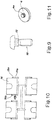
- Screw 10 as shown in fig. 9 , is fully similar to a partially un-threaded, conventional, hexagonal screw, wherein, however, a flange 12 is provided between the head and the threading. Once the screw has been inserted, the flange acts as engagement element against the wall of the second jaw, so that the unlosability of the screw is guaranteed.
- the screw-in seat 8 on the first jaw consists, according to the first embodiment, of an inside-threading bush, embedded in said parallelepiped body 6.
- the hole 11 for housing tightening screw 10 in the second jaw has a crosswise notch, apt to allow elastic spreading apart, and consequently ease the pressure-insertion of the screw flange.
- the centrally arranged parallelepiped body 6 is flanked laterally by two smaller shoulders 6a, 6b, which guarantee the perfect housing of arms 9a, 9b and the engagement between parallelepiped body 6 and the internal surface of the second jaw.
- each one of the lateral walls of said parallelepiped body 6 of the first jaw there are provided guiding grooves 13 with each one of which an articulating pin 14a, 14b engages, protruding inwards from the ends of said retaining arms 9a, 9b of the second jaw.
- engagement pins 14a, 14b have a square-base profile with a bevelled edge in a front-low position. This allows to ease the sliding of each one of pins 14a, 14b along the respective guiding groove 13 and to provide greater resistance, causing pins 14a, 14b to rest with a whole wall thereof against the support surface when the clamp system is brought into tension.
- cavity 15 - provided to act as the housing of said parallelepiped body 6 of the first jaw - is arranged so as to be able to house also at least a possible interchangeable spacer insert 16, essentially shaped as a small plate.
- each insert 16 is equipped with two ribs 17a, 17b, at least partially protruding from the opposite edges of said spacer insert 16.
- cavity 15 there are provided two rectilinear, parallel, opposite grooves 18a, 18b in correspondence of the lateral walls thereof.
- Such grooves 18b are intended to house said ribs 17a, 17b by snap fit engagement.
- the ribs 17a, 17b protruding from the opposite edges of such spacer insert 16 have a bevelled groove 19a, 19b for the snap-engagement with a tooth 20a, 20b provided along said grooves 18a, 18b.
- the selling kit of every panel clamp according to this embodiment contains a series of spacer inserts, the thicknesses of which vary, for example between 1 and 10 mm, the function of which is better described here in the following.
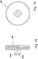
- the first jaw 1 is shaped so that parallelepiped body 6 has on the upper surface thereof a threaded cylindrical recess 21.
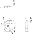
- a screw-in disc 22 is pivoted so that the centre thereof lies in correspondence of the thrust centre 23 of jaw 2.
- retaining arms 9a, 9b depart from the base of jaw 2, aligned with the tightening surface thereof.
- the ends of said retaining arms 9a, 9b are folded at 90° and mutually opposite, and have - in correspondence of the opposite end surface - the already described pins 14a, 14b for engagement with guiding groove 13.
- Such a configuration in the engagement with jaw 1, causes retaining arms 9a, 9b to be keyed on below guiding groove 13 of jaw 1, and makes the mutual engagement even more secure.
- said disc is equipped, on the extension of the axis thereof, with a pair of opposite pins 24a, 24b, intended for the engagement with an undercut cavity 25 arranged in correspondence of thrust centre 23.
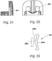
- a third embodiment, illustrated in figs. 20 to 22 shows an alternative solution, wherein on said first jaw 1 windows 26 are provided on the engagement surface with the panel which are apt to house bodies engaging with the panel wall which are described in the following.
- windows 26 are provided on the engagement surface with the panel which are apt to house bodies engaging with the panel wall which are described in the following.
- cavities 27 are provided for the housing of said engagement bodies.
- Such an engagement element 28 may consist of a rubber element or of a plastic spring. Said spring may have an alternative shape from the illustrated one, despite maintaining the same engagement function reported above.
- the operation of the clamp appears evident from the description of the components. Only in the case of the first embodiment must the operator simply insert a possible spacer insert 16 into the cavity 15 of the second jaw; the choice of the thickness of the insert will be determined according to the thickness of the panel the operator wants to fasten, so as to ensure a perfect parallelism of the first sides of the jaws during the tightening against the panel. In all cases, the operator inserts - wherever it has not been provided yet during packing, the second jaw in engagement with the first jaw, bringing pins 14a, 14b into engagement with guiding groove 13, then bringing the second jaw into an open position, i.e. substantially in a direction perpendicular with respect to jaw 1.
- the operator will then have to lock the first jaw to a fixed support by introducing the head of a screw (not shown) into recess 7, and the tightening through a suitable service hole arranged at the top of parallelepiped body 6.
- the operator acts on the second jaw, bringing it into tightening position, and then locking the screw and bringing into mutual engagement the two jaws.
- the tightening of screw 10 brings in contact parallelepiped body 6 and spacer 16 at the moment in which the two plates 4 engage in a secure and final way with the panel.
- screw 22 will bring jaw 2 to slide towards jaw 1, up to the moment of engagement of the relevant surfaces, possibly equipped with plate, with the panel: the two jaws will not necessarily have to be in contact.
- the two jaws 1, 2 are kept in mutual, unlosable engagement, without the detachment being possible, at least until jaw 1 is removed from the support.
- screw 10 for the mutual tightening of the two jaws is unlosable, thanks to the engagement between retaining flange 12 and the corresponding hole 11 suitably provided with a crosswise notch, which allows the elastic spreading apart thereof.
Landscapes
- Engineering & Computer Science (AREA)
- General Engineering & Computer Science (AREA)
- Mechanical Engineering (AREA)
- Clamps And Clips (AREA)
- Connection Of Plates (AREA)
- Working Measures On Existing Buildindgs (AREA)
- Hand Tools For Fitting Together And Separating, Or Other Hand Tools (AREA)
- Mounting Of Printed Circuit Boards And The Like (AREA)
- Gripping Jigs, Holding Jigs, And Positioning Jigs (AREA)
Priority Applications (1)
| Application Number | Priority Date | Filing Date | Title |
|---|---|---|---|
| PL11744070T PL2585722T3 (pl) | 2010-06-25 | 2011-06-24 | Zacisk podpory panelu |
Applications Claiming Priority (2)
| Application Number | Priority Date | Filing Date | Title |
|---|---|---|---|
| IT000218U ITMI20100218U1 (it) | 2010-06-25 | 2010-06-25 | Pinza per il supporto di pannelli |
| PCT/IB2011/052796 WO2011161659A1 (en) | 2010-06-25 | 2011-06-24 | Panel support clamp |
Publications (2)
| Publication Number | Publication Date |
|---|---|
| EP2585722A1 EP2585722A1 (en) | 2013-05-01 |
| EP2585722B1 true EP2585722B1 (en) | 2018-10-24 |
Family
ID=43740541
Family Applications (1)
| Application Number | Title | Priority Date | Filing Date |
|---|---|---|---|
| EP11744070.1A Active EP2585722B1 (en) | 2010-06-25 | 2011-06-24 | Panel support clamp |
Country Status (8)
| Country | Link |
|---|---|
| US (1) | US9352452B2 (pl) |
| EP (1) | EP2585722B1 (pl) |
| CN (1) | CN102959253B (pl) |
| ES (1) | ES2707233T3 (pl) |
| IT (1) | ITMI20100218U1 (pl) |
| PL (1) | PL2585722T3 (pl) |
| TR (1) | TR201900302T4 (pl) |
| WO (1) | WO2011161659A1 (pl) |
Families Citing this family (5)
| Publication number | Priority date | Publication date | Assignee | Title |
|---|---|---|---|---|
| ITMI20100218U1 (it) * | 2010-06-25 | 2011-12-26 | Elesa Spa | Pinza per il supporto di pannelli |
| US20200165818A1 (en) * | 2017-07-10 | 2020-05-28 | Mumble By Design Pty Ltd | Panel stand assembly |
| CN109830753B (zh) * | 2018-12-19 | 2024-07-02 | 无锡先导智能装备股份有限公司 | 一种夹具及封口设备 |
| CN113320213B (zh) * | 2021-06-02 | 2022-06-07 | 江西耐乐铜业有限公司 | 一种超薄沟槽管旋压式直拉装置 |
| CN114776674B (zh) * | 2022-04-26 | 2022-11-11 | 广东朗哥家具实业有限公司 | 一种智能可调精密自锁式家具板体用夹持装置 |
Family Cites Families (10)
| Publication number | Priority date | Publication date | Assignee | Title |
|---|---|---|---|---|
| US3845538A (en) * | 1973-06-26 | 1974-11-05 | Amp Inc | Hand tool |
| CN2358263Y (zh) * | 1999-01-12 | 2000-01-12 | 龙口市北方工具有限公司 | 一种紧固夹 |
| US6032939A (en) * | 1999-07-19 | 2000-03-07 | Chen; Jenn-Tzong | Clamp device |
| GB2410527B (en) * | 2002-11-29 | 2006-04-19 | Tyco Europe Metal Framing Ltd | Clamp |
| CN201003537Y (zh) * | 2007-01-16 | 2008-01-09 | 方大集团股份有限公司 | 一种连接结构 |
| CN201152447Y (zh) * | 2008-01-15 | 2008-11-19 | 长荧有限公司 | 物品固定装置 |
| US8505892B2 (en) * | 2009-10-19 | 2013-08-13 | Charles Seidel | Bar clamp assembly and workpiece support members |
| ITMI20100218U1 (it) * | 2010-06-25 | 2011-12-26 | Elesa Spa | Pinza per il supporto di pannelli |
| EP2581170B1 (en) * | 2011-10-13 | 2020-04-29 | PHD, Inc. | Gripper with force-multiplying mechanism |
| DE202013103810U1 (de) * | 2013-08-22 | 2013-09-04 | Röhm Gmbh | Zentrischspanner |
-
2010
- 2010-06-25 IT IT000218U patent/ITMI20100218U1/it unknown
-
2011
- 2011-06-24 WO PCT/IB2011/052796 patent/WO2011161659A1/en not_active Ceased
- 2011-06-24 EP EP11744070.1A patent/EP2585722B1/en active Active
- 2011-06-24 US US13/805,617 patent/US9352452B2/en active Active
- 2011-06-24 CN CN201180031444.6A patent/CN102959253B/zh active Active
- 2011-06-24 TR TR2019/00302T patent/TR201900302T4/tr unknown
- 2011-06-24 ES ES11744070T patent/ES2707233T3/es active Active
- 2011-06-24 PL PL11744070T patent/PL2585722T3/pl unknown
Non-Patent Citations (1)
| Title |
|---|
| None * |
Also Published As
| Publication number | Publication date |
|---|---|
| TR201900302T4 (tr) | 2019-02-21 |
| PL2585722T3 (pl) | 2019-04-30 |
| WO2011161659A1 (en) | 2011-12-29 |
| US9352452B2 (en) | 2016-05-31 |
| CN102959253A (zh) | 2013-03-06 |
| ES2707233T3 (es) | 2019-04-03 |
| CN102959253B (zh) | 2016-04-20 |
| EP2585722A1 (en) | 2013-05-01 |
| ITMI20100218U1 (it) | 2011-12-26 |
| US20130086776A1 (en) | 2013-04-11 |
Similar Documents
| Publication | Publication Date | Title |
|---|---|---|
| EP2585722B1 (en) | Panel support clamp | |
| US11444438B2 (en) | Switch cabinet frame structure having closed base frame | |
| US20120306138A1 (en) | Clamping device | |
| US10516239B2 (en) | Holding frame and method for producing same | |
| EP3146381B1 (en) | Hinge device for eyeglasses | |
| US20070154258A1 (en) | Fitting with an arresting device | |
| US8475086B2 (en) | Tool cassette | |
| ITUD20130017U1 (it) | Gruppo per porta per doccia | |
| TWI674348B (zh) | 刮刀 | |
| CA2928519C (en) | Fastener installation in composite panels with fastener insert | |
| CA3053475A1 (en) | Simply fitted furniture hinge | |
| JP3175277U (ja) | 家具連結部材 | |
| CA2975763C (en) | Hand tool with reliable connections | |
| BR112015024151B1 (pt) | Meio de conexão | |
| US20210172467A1 (en) | Connecting element for connecting profile elements | |
| CN101666345A (zh) | 凹槽螺母 | |
| US8302282B2 (en) | System and/or assembly for installing fastening devices and method of installing fastening devices using the system or assembly | |
| CN109891699A (zh) | 母线支架及相应的布置结构 | |
| EP3148766B1 (en) | A mould tool for injection moulding | |
| US9736954B2 (en) | Retaining device for power distribution unit | |
| EP1905937A2 (en) | Apparatus for mutually stably connecting profiled elements | |
| US12221990B2 (en) | Fastener assembly for blind mounting | |
| AU2015268680B2 (en) | Fastening device for fastening an installation box in a wall-shell opening | |
| EP2918764A1 (en) | Securing device for securing a glass panel to a profile | |
| KR20130033103A (ko) | 유로폼의 고정장치 |
Legal Events
| Date | Code | Title | Description |
|---|---|---|---|
| PUAI | Public reference made under article 153(3) epc to a published international application that has entered the european phase |
Free format text: ORIGINAL CODE: 0009012 |
|
| 17P | Request for examination filed |
Effective date: 20130118 |
|
| AK | Designated contracting states |
Kind code of ref document: A1 Designated state(s): AL AT BE BG CH CY CZ DE DK EE ES FI FR GB GR HR HU IE IS IT LI LT LU LV MC MK MT NL NO PL PT RO RS SE SI SK SM TR |
|
| DAX | Request for extension of the european patent (deleted) | ||
| GRAP | Despatch of communication of intention to grant a patent |
Free format text: ORIGINAL CODE: EPIDOSNIGR1 |
|
| STAA | Information on the status of an ep patent application or granted ep patent |
Free format text: STATUS: GRANT OF PATENT IS INTENDED |
|
| INTG | Intention to grant announced |
Effective date: 20180515 |
|
| GRAS | Grant fee paid |
Free format text: ORIGINAL CODE: EPIDOSNIGR3 |
|
| GRAA | (expected) grant |
Free format text: ORIGINAL CODE: 0009210 |
|
| STAA | Information on the status of an ep patent application or granted ep patent |
Free format text: STATUS: THE PATENT HAS BEEN GRANTED |
|
| AK | Designated contracting states |
Kind code of ref document: B1 Designated state(s): AL AT BE BG CH CY CZ DE DK EE ES FI FR GB GR HR HU IE IS IT LI LT LU LV MC MK MT NL NO PL PT RO RS SE SI SK SM TR |
|
| REG | Reference to a national code |
Ref country code: GB Ref legal event code: FG4D |
|
| REG | Reference to a national code |
Ref country code: CH Ref legal event code: EP |
|
| REG | Reference to a national code |
Ref country code: IE Ref legal event code: FG4D |
|
| REG | Reference to a national code |
Ref country code: AT Ref legal event code: REF Ref document number: 1057005 Country of ref document: AT Kind code of ref document: T Effective date: 20181115 |
|
| REG | Reference to a national code |
Ref country code: DE Ref legal event code: R096 Ref document number: 602011053206 Country of ref document: DE |
|
| REG | Reference to a national code |
Ref country code: NL Ref legal event code: MP Effective date: 20181024 |
|
| REG | Reference to a national code |
Ref country code: LT Ref legal event code: MG4D |
|
| REG | Reference to a national code |
Ref country code: AT Ref legal event code: MK05 Ref document number: 1057005 Country of ref document: AT Kind code of ref document: T Effective date: 20181024 |
|
| PG25 | Lapsed in a contracting state [announced via postgrant information from national office to epo] |
Ref country code: NL Free format text: LAPSE BECAUSE OF FAILURE TO SUBMIT A TRANSLATION OF THE DESCRIPTION OR TO PAY THE FEE WITHIN THE PRESCRIBED TIME-LIMIT Effective date: 20181024 |
|
| REG | Reference to a national code |
Ref country code: ES Ref legal event code: FG2A Ref document number: 2707233 Country of ref document: ES Kind code of ref document: T3 Effective date: 20190403 |
|
| PG25 | Lapsed in a contracting state [announced via postgrant information from national office to epo] |
Ref country code: LV Free format text: LAPSE BECAUSE OF FAILURE TO SUBMIT A TRANSLATION OF THE DESCRIPTION OR TO PAY THE FEE WITHIN THE PRESCRIBED TIME-LIMIT Effective date: 20181024 Ref country code: HR Free format text: LAPSE BECAUSE OF FAILURE TO SUBMIT A TRANSLATION OF THE DESCRIPTION OR TO PAY THE FEE WITHIN THE PRESCRIBED TIME-LIMIT Effective date: 20181024 Ref country code: LT Free format text: LAPSE BECAUSE OF FAILURE TO SUBMIT A TRANSLATION OF THE DESCRIPTION OR TO PAY THE FEE WITHIN THE PRESCRIBED TIME-LIMIT Effective date: 20181024 Ref country code: BG Free format text: LAPSE BECAUSE OF FAILURE TO SUBMIT A TRANSLATION OF THE DESCRIPTION OR TO PAY THE FEE WITHIN THE PRESCRIBED TIME-LIMIT Effective date: 20190124 Ref country code: FI Free format text: LAPSE BECAUSE OF FAILURE TO SUBMIT A TRANSLATION OF THE DESCRIPTION OR TO PAY THE FEE WITHIN THE PRESCRIBED TIME-LIMIT Effective date: 20181024 Ref country code: NO Free format text: LAPSE BECAUSE OF FAILURE TO SUBMIT A TRANSLATION OF THE DESCRIPTION OR TO PAY THE FEE WITHIN THE PRESCRIBED TIME-LIMIT Effective date: 20190124 Ref country code: IS Free format text: LAPSE BECAUSE OF FAILURE TO SUBMIT A TRANSLATION OF THE DESCRIPTION OR TO PAY THE FEE WITHIN THE PRESCRIBED TIME-LIMIT Effective date: 20190224 Ref country code: AT Free format text: LAPSE BECAUSE OF FAILURE TO SUBMIT A TRANSLATION OF THE DESCRIPTION OR TO PAY THE FEE WITHIN THE PRESCRIBED TIME-LIMIT Effective date: 20181024 |
|
| PG25 | Lapsed in a contracting state [announced via postgrant information from national office to epo] |
Ref country code: RS Free format text: LAPSE BECAUSE OF FAILURE TO SUBMIT A TRANSLATION OF THE DESCRIPTION OR TO PAY THE FEE WITHIN THE PRESCRIBED TIME-LIMIT Effective date: 20181024 Ref country code: GR Free format text: LAPSE BECAUSE OF FAILURE TO SUBMIT A TRANSLATION OF THE DESCRIPTION OR TO PAY THE FEE WITHIN THE PRESCRIBED TIME-LIMIT Effective date: 20190125 Ref country code: SE Free format text: LAPSE BECAUSE OF FAILURE TO SUBMIT A TRANSLATION OF THE DESCRIPTION OR TO PAY THE FEE WITHIN THE PRESCRIBED TIME-LIMIT Effective date: 20181024 Ref country code: AL Free format text: LAPSE BECAUSE OF FAILURE TO SUBMIT A TRANSLATION OF THE DESCRIPTION OR TO PAY THE FEE WITHIN THE PRESCRIBED TIME-LIMIT Effective date: 20181024 Ref country code: PT Free format text: LAPSE BECAUSE OF FAILURE TO SUBMIT A TRANSLATION OF THE DESCRIPTION OR TO PAY THE FEE WITHIN THE PRESCRIBED TIME-LIMIT Effective date: 20190224 |
|
| REG | Reference to a national code |
Ref country code: DE Ref legal event code: R097 Ref document number: 602011053206 Country of ref document: DE |
|
| PG25 | Lapsed in a contracting state [announced via postgrant information from national office to epo] |
Ref country code: DK Free format text: LAPSE BECAUSE OF FAILURE TO SUBMIT A TRANSLATION OF THE DESCRIPTION OR TO PAY THE FEE WITHIN THE PRESCRIBED TIME-LIMIT Effective date: 20181024 Ref country code: CZ Free format text: LAPSE BECAUSE OF FAILURE TO SUBMIT A TRANSLATION OF THE DESCRIPTION OR TO PAY THE FEE WITHIN THE PRESCRIBED TIME-LIMIT Effective date: 20181024 |
|
| PG25 | Lapsed in a contracting state [announced via postgrant information from national office to epo] |
Ref country code: RO Free format text: LAPSE BECAUSE OF FAILURE TO SUBMIT A TRANSLATION OF THE DESCRIPTION OR TO PAY THE FEE WITHIN THE PRESCRIBED TIME-LIMIT Effective date: 20181024 Ref country code: SK Free format text: LAPSE BECAUSE OF FAILURE TO SUBMIT A TRANSLATION OF THE DESCRIPTION OR TO PAY THE FEE WITHIN THE PRESCRIBED TIME-LIMIT Effective date: 20181024 Ref country code: SM Free format text: LAPSE BECAUSE OF FAILURE TO SUBMIT A TRANSLATION OF THE DESCRIPTION OR TO PAY THE FEE WITHIN THE PRESCRIBED TIME-LIMIT Effective date: 20181024 Ref country code: EE Free format text: LAPSE BECAUSE OF FAILURE TO SUBMIT A TRANSLATION OF THE DESCRIPTION OR TO PAY THE FEE WITHIN THE PRESCRIBED TIME-LIMIT Effective date: 20181024 |
|
| PLBE | No opposition filed within time limit |
Free format text: ORIGINAL CODE: 0009261 |
|
| STAA | Information on the status of an ep patent application or granted ep patent |
Free format text: STATUS: NO OPPOSITION FILED WITHIN TIME LIMIT |
|
| 26N | No opposition filed |
Effective date: 20190725 |
|
| PG25 | Lapsed in a contracting state [announced via postgrant information from national office to epo] |
Ref country code: SI Free format text: LAPSE BECAUSE OF FAILURE TO SUBMIT A TRANSLATION OF THE DESCRIPTION OR TO PAY THE FEE WITHIN THE PRESCRIBED TIME-LIMIT Effective date: 20181024 |
|
| PG25 | Lapsed in a contracting state [announced via postgrant information from national office to epo] |
Ref country code: MC Free format text: LAPSE BECAUSE OF FAILURE TO SUBMIT A TRANSLATION OF THE DESCRIPTION OR TO PAY THE FEE WITHIN THE PRESCRIBED TIME-LIMIT Effective date: 20181024 |
|
| REG | Reference to a national code |
Ref country code: CH Ref legal event code: PL |
|
| REG | Reference to a national code |
Ref country code: BE Ref legal event code: MM Effective date: 20190630 |
|
| PG25 | Lapsed in a contracting state [announced via postgrant information from national office to epo] |
Ref country code: IE Free format text: LAPSE BECAUSE OF NON-PAYMENT OF DUE FEES Effective date: 20190624 |
|
| PG25 | Lapsed in a contracting state [announced via postgrant information from national office to epo] |
Ref country code: LI Free format text: LAPSE BECAUSE OF NON-PAYMENT OF DUE FEES Effective date: 20190630 Ref country code: CH Free format text: LAPSE BECAUSE OF NON-PAYMENT OF DUE FEES Effective date: 20190630 Ref country code: LU Free format text: LAPSE BECAUSE OF NON-PAYMENT OF DUE FEES Effective date: 20190624 Ref country code: BE Free format text: LAPSE BECAUSE OF NON-PAYMENT OF DUE FEES Effective date: 20190630 |
|
| PG25 | Lapsed in a contracting state [announced via postgrant information from national office to epo] |
Ref country code: CY Free format text: LAPSE BECAUSE OF FAILURE TO SUBMIT A TRANSLATION OF THE DESCRIPTION OR TO PAY THE FEE WITHIN THE PRESCRIBED TIME-LIMIT Effective date: 20181024 |
|
| PG25 | Lapsed in a contracting state [announced via postgrant information from national office to epo] |
Ref country code: MT Free format text: LAPSE BECAUSE OF FAILURE TO SUBMIT A TRANSLATION OF THE DESCRIPTION OR TO PAY THE FEE WITHIN THE PRESCRIBED TIME-LIMIT Effective date: 20181024 Ref country code: HU Free format text: LAPSE BECAUSE OF FAILURE TO SUBMIT A TRANSLATION OF THE DESCRIPTION OR TO PAY THE FEE WITHIN THE PRESCRIBED TIME-LIMIT; INVALID AB INITIO Effective date: 20110624 |
|
| PG25 | Lapsed in a contracting state [announced via postgrant information from national office to epo] |
Ref country code: MK Free format text: LAPSE BECAUSE OF FAILURE TO SUBMIT A TRANSLATION OF THE DESCRIPTION OR TO PAY THE FEE WITHIN THE PRESCRIBED TIME-LIMIT Effective date: 20181024 |
|
| P01 | Opt-out of the competence of the unified patent court (upc) registered |
Effective date: 20230527 |
|
| PGFP | Annual fee paid to national office [announced via postgrant information from national office to epo] |
Ref country code: PL Payment date: 20250423 Year of fee payment: 15 Ref country code: DE Payment date: 20250528 Year of fee payment: 15 |
|
| PGFP | Annual fee paid to national office [announced via postgrant information from national office to epo] |
Ref country code: GB Payment date: 20250527 Year of fee payment: 15 |
|
| PGFP | Annual fee paid to national office [announced via postgrant information from national office to epo] |
Ref country code: IT Payment date: 20250528 Year of fee payment: 15 |
|
| PGFP | Annual fee paid to national office [announced via postgrant information from national office to epo] |
Ref country code: FR Payment date: 20250527 Year of fee payment: 15 |
|
| PGFP | Annual fee paid to national office [announced via postgrant information from national office to epo] |
Ref country code: TR Payment date: 20250617 Year of fee payment: 15 |
|
| PGFP | Annual fee paid to national office [announced via postgrant information from national office to epo] |
Ref country code: ES Payment date: 20250728 Year of fee payment: 15 |