EP2585232B1 - Anti-drying device and method - Google Patents
Anti-drying device and method Download PDFInfo
- Publication number
- EP2585232B1 EP2585232B1 EP11749902.0A EP11749902A EP2585232B1 EP 2585232 B1 EP2585232 B1 EP 2585232B1 EP 11749902 A EP11749902 A EP 11749902A EP 2585232 B1 EP2585232 B1 EP 2585232B1
- Authority
- EP
- European Patent Office
- Prior art keywords
- container
- drying device
- delivery
- fluid
- liquid
- Prior art date
- Legal status (The legal status is an assumption and is not a legal conclusion. Google has not performed a legal analysis and makes no representation as to the accuracy of the status listed.)
- Active
Links
Images



Classifications
-
- B—PERFORMING OPERATIONS; TRANSPORTING
- B05—SPRAYING OR ATOMISING IN GENERAL; APPLYING FLUENT MATERIALS TO SURFACES, IN GENERAL
- B05C—APPARATUS FOR APPLYING FLUENT MATERIALS TO SURFACES, IN GENERAL
- B05C11/00—Component parts, details or accessories not specifically provided for in groups B05C1/00 - B05C9/00
- B05C11/11—Vats or other containers for liquids or other fluent materials
-
- B—PERFORMING OPERATIONS; TRANSPORTING
- B65—CONVEYING; PACKING; STORING; HANDLING THIN OR FILAMENTARY MATERIAL
- B65B—MACHINES, APPARATUS OR DEVICES FOR, OR METHODS OF, PACKAGING ARTICLES OR MATERIALS; UNPACKING
- B65B31/00—Packaging articles or materials under special atmospheric or gaseous conditions; Adding propellants to aerosol containers
- B65B31/04—Evacuating, pressurising or gasifying filled containers or wrappers by means of nozzles through which air or other gas, e.g. an inert gas, is withdrawn or supplied
-
- B—PERFORMING OPERATIONS; TRANSPORTING
- B05—SPRAYING OR ATOMISING IN GENERAL; APPLYING FLUENT MATERIALS TO SURFACES, IN GENERAL
- B05B—SPRAYING APPARATUS; ATOMISING APPARATUS; NOZZLES
- B05B15/00—Details of spraying plant or spraying apparatus not otherwise provided for; Accessories
- B05B15/50—Arrangements for cleaning; Arrangements for preventing deposits, drying-out or blockage; Arrangements for detecting improper discharge caused by the presence of foreign matter
-
- B—PERFORMING OPERATIONS; TRANSPORTING
- B05—SPRAYING OR ATOMISING IN GENERAL; APPLYING FLUENT MATERIALS TO SURFACES, IN GENERAL
- B05C—APPARATUS FOR APPLYING FLUENT MATERIALS TO SURFACES, IN GENERAL
- B05C21/00—Accessories or implements for use in connection with applying liquids or other fluent materials to surfaces, not provided for in groups B05C1/00 - B05C19/00
-
- B—PERFORMING OPERATIONS; TRANSPORTING
- B08—CLEANING
- B08B—CLEANING IN GENERAL; PREVENTION OF FOULING IN GENERAL
- B08B15/00—Preventing escape of dirt or fumes from the area where they are produced; Collecting or removing dirt or fumes from that area
- B08B15/02—Preventing escape of dirt or fumes from the area where they are produced; Collecting or removing dirt or fumes from that area using chambers or hoods covering the area
-
- B—PERFORMING OPERATIONS; TRANSPORTING
- B08—CLEANING
- B08B—CLEANING IN GENERAL; PREVENTION OF FOULING IN GENERAL
- B08B17/00—Methods preventing fouling
-
- B—PERFORMING OPERATIONS; TRANSPORTING
- B65—CONVEYING; PACKING; STORING; HANDLING THIN OR FILAMENTARY MATERIAL
- B65D—CONTAINERS FOR STORAGE OR TRANSPORT OF ARTICLES OR MATERIALS, e.g. BAGS, BARRELS, BOTTLES, BOXES, CANS, CARTONS, CRATES, DRUMS, JARS, TANKS, HOPPERS, FORWARDING CONTAINERS; ACCESSORIES, CLOSURES, OR FITTINGS THEREFOR; PACKAGING ELEMENTS; PACKAGES
- B65D43/00—Lids or covers for rigid or semi-rigid containers
Definitions
- the present invention concerns an anti-drying device to prevent the drying of fluid and semi-fluid products, pastes, gels, creams such as for example coloring products, pigments or paints, residues on delivery needles of a machine or device at least for the delivery and possibly for the automatic preparation, mixing and distribution of fluid coloring products, for example coloring liquids, paint bases, varnishes, enamels, inks or other fluid coloring substances.
- fluid coloring products for example coloring liquids, paint bases, varnishes, enamels, inks or other fluid coloring substances.
- Devices or machines to dispense or deliver fluid and semi-fluid products, pastes, gels, creams such as coloring products, pigments or paints are known, and are able to introduce a measured quantity of a product into a receptacle, containing, for example, a paint base to obtain the coloring product desired.
- Such devices or delivery machines normally comprise a delivery unit, or dispensing head, by means of which a desired quantity of one or more fluid products is delivered into a receptacle, normally containing a paint base.
- the delivery unit is typically mobile between an idle position and an operating position in which it cooperates with the container and traditionally comprises a plurality of delivery needles by means of which the lid of the container containing the paint base is perforated, and the fluid product is delivered inside it.
- a known delivery unit is described in the European patent application EP-A-2.040.830 in the name of the Applicant.
- the residual fluid product on the tip of the delivery needles, in contact with the air, tends to dry, usually in the period of time between one delivery step and the next, with negative effects on the performance of the delivery device or machine.
- a conditioning device described in the European patent EP-B-1.494.959 or an anti-drying device described in the aforementioned European patent EP-2.040.830 .
- Document US-A-2008/210774 describes an anti-drying device in accordance with the preamble of claim 1 to dampen the delivery nozzles of colorants which comprises a housing which defines a first chamber to house a reserve tank for the water and an open tray to hold a certain volume of water and in which a heating element is provided to vaporize the water. The vapor passes into a second open chamber of the tray, where the nozzles, when they are idle, are exposed to the vapor.
- Purpose of the present invention is to achieve an anti-drying device which has even greater performance and efficiency than known anti-drying devices, which is economical, rapid, functional, without negatively influencing the functioning of other components of the associated dispensing machine.
- the present invention is an anti-drying device in accordance with claim 1, while the dependent claims describe other characteristics of the invention or variants to the main inventive idea.
- an anti-drying device can be used to humidify the delivery means of fluid and semi-fluid products, pastes, gels, creams such as for example coloring products, pigments or paints, of a machine at least for the delivery and possibly for the automatic preparation, mixing and distribution of at least a fluid product into a closed receptacle, for example for the delivery of a fluid coloring product into a receptacle which contains a paint base.
- the anti-drying device of the present invention comprises a container or receptacle hermetically closed by means of a closing lid and which has an inner volume inside which there is a fluid, liquid and/or vapor, suitable to humidify possible residues of fluid product on the delivery means.
- the closing lid is configured both to confine the liquid and/or the vapor inside the container and also to introduce and house, through at least one of its portions, at least the ends of the delivery means inside the closed container, so that they are in contact with the liquid and/or vapor so as to prevent the drying thereof.
- the delivery machine of the fluid product When the delivery machine of the fluid product is idle, it will be possible to insert the delivery means into the container in which the liquid and/or vapor is present, preventing the drying of possible residues of fluid product present thereon.
- the delivery means for example the tips of the needles which deliver the coloring substances, are prevented from drying during periods of idleness.
- the vaporization times are more rapid and, if necessary, there will be less heat energy needed.
- the vapor generated by heating, or in a natural way by exploiting the vapor tension of the liquid at ambient temperature remains confined in the container, and this, as well as eliminating the creation of undesired humidity on the components of the dispensing machine and outside it, makes the integration of liquid unnecessary.
- the container is provided with a closing lid which has a portion made, at least partly, with a membrane of an elastic material able to dilate, when the delivery means are inserted through it in order to be kept damp, during the performance of the anti-drying action, and to re-compact, when the delivery means are removed from the container, thus preventing the fluid and vapor contained therein from leaking out.
- the use of the membrane which acts as a closing element is advantageous because it allows an optimal control of the humidity inside the container.
- the presence of the membrane on the container has the advantage that, when the delivery means are removed through it, there is an effect of scraping the residues of fluid product possibly present, contributing to increase the cleanliness of the delivery means, obtaining a considerable improvement in the delivery.
- the anti-drying device of the present invention comprises a mechanical arm, pivoted on a vertical pin which bears a support plate of the fluid container at one end, the mechanical arm being rotatable between a first operating position in which the container is in cooperation with the delivery means for the anti-drying action, and a second operating position, rotated with respect to the first, where it is disengaged.
- the present invention also concerns a method to humidify delivery means in accordance with claim 12 for fluid and semi-fluid products, pastes, gels, creams such as for example coloring products, pigments or paints, of a machine at least for the automatic delivery of at least a fluid product into a closed container.
- the method comprises a step of introducing into a container or receptacle, hermetically closed by means of a closing lid and which has an internal volume in which there is a fluid, liquid and/or vapor, at least the ends of the delivery means through a portion of the closing lid, confining the liquid and/or vapor inside the container so that at least the ends of the delivery means are in contact with the liquid and/or vapor, so as to prevent them from drying out.
- an anti-drying device 10 can be used to prevent the drying of residues of fluid products in delivery needles 74 of a delivery device 21 of a machine 75 to automatically deliver fluid coloring products in closed receptacles 11.
- the anti-drying device 10 comprises a container or receptacle 79, hermetically closed by means of a closing lid 82 and substantially similar to the recipients 11, inside which a fluid or liquid is present, such as water and/or aqueous vapor, and a support plate 78 on which the container 79 is disposed, comprising heating means 81, in this case an electric resistance integrated into it, by means of which to heat-regulate the support plate 78 in order to generate and maintain a desired quantity of liquid and vapor inside the container 79.
- the heating means 81 can be set to a desired temperature, to obtain the desired balance between liquid and vapor inside the container 79.
- the closing lid 82 is configured both to confine the liquid and/or vapor inside the container 79 and also to allow the introduction, through at least one of its portions, of the delivery needles 74 of the delivery device 21 inside the closed container 79 so that they are in contact with the liquid and/or vapor, so as to prevent them from drying out.
- the same closed container 79 which contains the liquid by means of which the anti-drying vapor is generated also comprises the heating means 81, achieving a more compact device.
- the container 79 since the container 79 is hermetically closed by the closing lid 82, the liquid which generates the vapor is not wasted, but remains confined inside the volume of the container 79, without needing topping up or integrations and also without dispersing inside or outside the machine 75. Moreover, as the container 79 is closed, even the heat energy required for evaporation will be less, with obvious saving in terms of time and costs.
- the container 79 is attached in a selectively removable way to the support plate 78.
- the container 79 is provided with releasable attachment means 72 ( fig. 6 ), of the bayonet type for example, able to cooperate with mating counter attachment means provided on the support plate 78, for an easy attachment to the support plate 78.
- the container 79 can be easily removed from the support plate 78 to guarantee easy access and cleaning by the specialized operator, seeing that, normally, after a certain number of hours of functioning, the liquid contained will have to be removed and substituted.
- the cleaning operation will be indicated by the operating system which manages the functioning of the device 10 by means of a suitable message.
- the sizes of the container 79 which can, for example, be a cylindrical shaped can, are configured to house inside it at least the part or end of the needles 74 on which, normally, there can be residue of fluid product which is delivered.
- a liquid for example water
- the closing lid 82 with which the container 79 is provided has a portion made, at least partly, with a membrane 83 of an elastic material able to dilate, when the delivery needles 74 are inserted through it in order to be kept damp, during the performance of the anti-drying action, and to re-compact, when the needles 74 are removed, preventing the liquid contained therein from leaking out.
- the membrane portion 83 of the closing lid 82 of the container 79 is sized in a manner coordinated with the overall plane bulk of the plurality of needles 74, so as to guarantee that each of them is inserted inside the container 79 for the anti-drying action.
- the anti-drying device is shown used in a machine 75 for the automatic preparation and distribution of fluid coloring products, contained in closed receptacles 11, which in this case comprises a support structure 12, divided into substantially three modular compartments 13, 14 and 15, integrated with each other, as described in the copending patent application in Italy of the Applicant n. UD2010A000126 with the same priority date and entitled "MACHINE FOR THE AUTOMATIC PREPARATION AND DISTRIBUTION OF FLUID COLORING PRODUCTS CONTAINED IN CLOSED RECEPTACLES".
- the receptacles 11 can be either metal, such as steel, or plastic material and can be a cylindrical shape or any other shape, such as for example a parallelepiped, with a square or rectangular base. Each of them can contain a fluid paint base, which can be for example transparent or white, to which a colorant is then added, substantially consisting of pigments.
- Each receptacle 11 can be closed by a lid provided at the center with a membrane, of a known type, which has the characteristic of being holed by one or more needles and closing automatically when each needle is removed, as is the case of the membrane 83 of the container 79.
- a plurality of tanks 20 are disposed ( fig. 1 ), which can be of any known type, for example as described in the European patent EP-B-1.744.826 , in the name of the present Applicant, in each of which a different coloring substance is contained.
- a delivery device 21 is disposed, which can be of any known type, for example as described in the Italian patent IT-B-1.370.076 , in the name of the present Applicant.
- the delivery device 21 is connected to the tanks 20 by means of pipes 23 ( figs. 4 and 5 ) of any known type.
- a mixing device 22 is disposed in this case, which can be of any known type, for example of the type described in the European patent EP-B-1.417.024 granted on 21.09.2005 to the Applicant.
- a loading station 25 ( figs. 1 and 3 ) is disposed, which comprises a plate 26, of a circular shape for example, which acts as a support element and centering member for one receptacle 11 at a time.
- the loading station 25 has a first vertical axis Z1 ( figs. 3 - 5 ).
- an access door 29 is disposed, of a semi-circular shape and comprising, in some forms of embodiment, two panels 29a and 29b, each of which has an angular development of 90° to act as a rotating bushing.
- transfer means 30 ( figs. 1 , 3 , 4 and 5 ) are able to selectively and automatically transfer the receptacle 11, together with the plate 26, both from the loading station 25 to the delivery device 21, along a first horizontal axis X, and from the delivery device 21 to the mixing device 22, along a second horizontal axis Y, perpendicular to the axis X, and vice versa, to return them to the loading station 25.
- data input means 50 are disposed, connected to a central control unit 59 ( fig. 1 ) and able to be actuated by the user in order to choose the sizes and the capacity of the receptacle 11, the type of paint base and/or the color of the fluid coloring product to be obtained.
- the delivery device 21 ( figs. 4 and 5 ) comprises a plate 73 on which the needles 74 are mounted, disposed parallel and concentric to the vertical axis Z2 and each connected to a corresponding pipe 23.
- the plate 73 is mobile vertically along the vertical axis Z2 by means of an electric motor, of a known type and not shown in the drawings, which is also controlled by the central control unit 59.
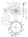
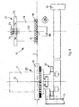
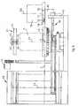
- the anti-drying device 10 ( figs. 3-6 ) used in the machine 75 comprises a mechanical arm 76, pivoted on a vertical pin 77 which bears the support plate 78 at one end, which can be heat-regulated with the electric resistance 81 integrated in it, on which the container 79 is removably disposed.
- the mechanical arm 76 is rotatable by means of an electric motor 80, controlled by the central control unit 59, between a first operating position in which it is aligned with the horizontal axis Y ( figs. 3 and 4 ) and a second operating position, rotated by 90° with respect to the first, that is, parallel to the horizontal axis X ( figs. 5 and 6 and shown by dashes in fig. 3 ).
- the container 79 In the first operating condition ( figs. 3 and 4 ) the container 79 is coaxial to the second vertical axis Z2 and the plate 73 is lowered against the container 79 ( fig. 4 ), so that the tips of the needles 74 are inside the latter, remaining damp thanks to the liquid and/or vapor contained therein. In the second operating position ( figs. 3 , 5 and 6 ) the container 79 is coaxial to a fourth vertical axis Z4, outside the bulk of the plate 26 and of the plate 73.
- the method with which the anti-drying device 10 as described heretofore is used functions in the machine 75 as follows.
- the user by means of the data input means 50, chooses and selects the characteristics of the specific fluid product that he intends to purchase.
- the user takes the type of receptacle 11 from a store or shelf which contains the type of paint base for example and which has the capacity he has chosen, and positions it in the loading station 25 ( fig. 1 ), centering it on the plate 26.
- the access door 29 ( figs. 2 and 3 ) is closed so that the two panels 29a and 29b are disposed in front of the receptacle 11 (position shown by dashes in figs. 2 and 3 ) and therefore so that nobody can access the loading station 25, until the end of the operating cycle.
- the central control unit 59 can automatically carry out a step to verify that the receptacle 11 is the type chosen by the user, and also that it is centered on the plate 26, possibly inviting the user to correct the positioning or substitute the receptacle 11.
- the central control unit 59 sets and activates the functioning of the heating means 81, in order to have the desired atmosphere saturated with vapor inside the container 79. Normally, at the beginning, the needles 74 of the delivery device 21 are inserted in the container 79, to prevent drying.
- the central control unit 59 automatically carries out a step of preparing the delivery device 21, lifting first the plate 73 ( fig. 5 ) and then rotating the mechanical arm 76 by 90° in a clockwise direction ( fig. 3 ), by means of the electric motor 80, to bring it together with the container 10 into the second operating position, aligned with the vertical axis Z4.
- a positioning step is then carried out, under the control of the central control unit 59, by means of the transfer means 30, to position the receptacle 11 aligned to the vertical axis Z2, instead of the container 79, and to deliver coloring substances inside the receptacle 11.
- the plate 73 of the delivery device 21 is lowered until the needles 74 have their tips inside the receptacle 11 (position shown by dashes in fig. 5 ).
- the pipes 23 then convey into the receptacle 11, by means of volumetric pumps of a known type and not shown in the drawings, the necessary quantity of coloring substance contained in the tanks 20, so as to achieve the shade of color chosen by the user.
- the plate 73 is raised.
- the central control unit 59 automatically carries out a second step of transferring the receptacle 11 (figs. 10 and 11) from the delivery device 21 (vertical axis Z2) to the mixing device 22 (vertical axis Z3), by means of the transfer means 30.
- the central control unit 59 then carries out a step of mixing the product contained inside the receptacle 11 (paint base plus coloring substances), commanding, in a known way, the mixing device 22, which stirs the receptacle 11 for a predetermined time.
- the central control unit 59 commands the inverse operations, until the receptacle 11 is returned to the loading station 25.
- the electric motor 80 returns the container 79 to the first operating position, aligned with the vertical axis Z2, and the plate 73 of the delivery device 21 is lowered to return the tips of the needles 74 inside the container 79 and thus prevent the possible residues from drying out, such as coloring pigments.
- the panels 29a and 29b ( figs 2 and 3 ) can then be returned (manually or automatically) to their initial condition behind the plate 26. At this point the user can remove the receptacle 11 containing inside it the coloring product he requested.
- the hermetically sealed container 79 can be the disposable type, and comprise inside it a liquid that has its own vapor tension, advantageously water or a suitable aqueous mixture, so as to generate a desired quantity of vapor which, thanks to the closing lid 82, stays confined inside the volume of the container 79, where the needles can be introduced for damping ( figs. 7 and 8 ).
- the heating means 81 might not be provided, as in fig. 8 , or they could be included, integrated in the support plate 78, to function as an auxiliary for the vaporization as in fig. 7 .
- the disposable container 79 is housed in a fixed external container 85 which advantageously has attachment means, for example bayonet type, for releasable attachment to the support plate 78 ( fig. 8 ).
- sensor means 87 can be provided, able to recognize the presence or absence of the container 79, so as to transmit a correlated warning signal by means of the central control unit 59 of the machine 75, so that it provides for the correct positioning of the container 79: this may be advantageous in the case of a disposable container 79 as described above.
- the sensor means 87 are for example embedded on the internal upper edge of the external fixed container 85.
- a sponge element 84 is provided ( fig. 8 ), preferably of the disposable type, associated above the container 79, for example interposed between the closing lid 82 with the membrane 83 and the container itself, the function of which is to collect any possible drops of colorant or dirt that remain on the surface of the needles 74 after the membrane 83 has been scraped.
Landscapes
- Engineering & Computer Science (AREA)
- Mechanical Engineering (AREA)
- Chemical & Material Sciences (AREA)
- Dispersion Chemistry (AREA)
- Drying Of Solid Materials (AREA)
- Paints Or Removers (AREA)
Description
- The present invention concerns an anti-drying device to prevent the drying of fluid and semi-fluid products, pastes, gels, creams such as for example coloring products, pigments or paints, residues on delivery needles of a machine or device at least for the delivery and possibly for the automatic preparation, mixing and distribution of fluid coloring products, for example coloring liquids, paint bases, varnishes, enamels, inks or other fluid coloring substances.
- Devices or machines to dispense or deliver fluid and semi-fluid products, pastes, gels, creams such as coloring products, pigments or paints are known, and are able to introduce a measured quantity of a product into a receptacle, containing, for example, a paint base to obtain the coloring product desired. Such devices or delivery machines normally comprise a delivery unit, or dispensing head, by means of which a desired quantity of one or more fluid products is delivered into a receptacle, normally containing a paint base. The delivery unit is typically mobile between an idle position and an operating position in which it cooperates with the container and traditionally comprises a plurality of delivery needles by means of which the lid of the container containing the paint base is perforated, and the fluid product is delivered inside it. A known delivery unit is described in the European patent application
EP-A-2.040.830 in the name of the Applicant. The residual fluid product on the tip of the delivery needles, in contact with the air, tends to dry, usually in the period of time between one delivery step and the next, with negative effects on the performance of the delivery device or machine. To overcome this disadvantage it is necessary to keep the delivery needles damp and to this end the Applicant proposed, in the past, a conditioning device described in the European patentEP-B-1.494.959 , or an anti-drying device described in the aforementioned European patentEP-2.040.830 . - Document
US-A-2008/210774 describes an anti-drying device in accordance with the preamble of claim 1 to dampen the delivery nozzles of colorants which comprises a housing which defines a first chamber to house a reserve tank for the water and an open tray to hold a certain volume of water and in which a heating element is provided to vaporize the water. The vapor passes into a second open chamber of the tray, where the nozzles, when they are idle, are exposed to the vapor. - Purpose of the present invention is to achieve an anti-drying device which has even greater performance and efficiency than known anti-drying devices, which is economical, rapid, functional, without negatively influencing the functioning of other components of the associated dispensing machine.
- The Applicant has devised, tested and embodied the present invention to overcome the shortcomings of the state of the art and to obtain these and other purposes and advantages. ,
- The present invention is an anti-drying device in accordance with claim 1, while the dependent claims describe other characteristics of the invention or variants to the main inventive idea.
- In accordance with the above purpose, an anti-drying device according to the present invention can be used to humidify the delivery means of fluid and semi-fluid products, pastes, gels, creams such as for example coloring products, pigments or paints, of a machine at least for the delivery and possibly for the automatic preparation, mixing and distribution of at least a fluid product into a closed receptacle, for example for the delivery of a fluid coloring product into a receptacle which contains a paint base.
- The anti-drying device of the present invention comprises a container or receptacle hermetically closed by means of a closing lid and which has an inner volume inside which there is a fluid, liquid and/or vapor, suitable to humidify possible residues of fluid product on the delivery means.
- The closing lid is configured both to confine the liquid and/or the vapor inside the container and also to introduce and house, through at least one of its portions, at least the ends of the delivery means inside the closed container, so that they are in contact with the liquid and/or vapor so as to prevent the drying thereof.
- When the delivery machine of the fluid product is idle, it will be possible to insert the delivery means into the container in which the liquid and/or vapor is present, preventing the drying of possible residues of fluid product present thereon. With the anti-drying device of the present invention, therefore, the delivery means, for example the tips of the needles which deliver the coloring substances, are prevented from drying during periods of idleness.
- The use of a liquid, typically water, which is partly vaporized or heated, or exploiting the natural tension of vapor at ambient temperature, creating an atmosphere saturated with vapor inside the container in which the delivery means are at least partly immersed, allows a more efficient humidifying action with respect to known anti-drying devices.
- Moreover, with the present invention, as the container is hermetically closed by the closing lid, the vaporization times are more rapid and, if necessary, there will be less heat energy needed. Moreover, the vapor generated by heating, or in a natural way by exploiting the vapor tension of the liquid at ambient temperature, remains confined in the container, and this, as well as eliminating the creation of undesired humidity on the components of the dispensing machine and outside it, makes the integration of liquid unnecessary.
- In some forms of embodiment, the container is provided with a closing lid which has a portion made, at least partly, with a membrane of an elastic material able to dilate, when the delivery means are inserted through it in order to be kept damp, during the performance of the anti-drying action, and to re-compact, when the delivery means are removed from the container, thus preventing the fluid and vapor contained therein from leaking out.
- The use of the membrane which acts as a closing element is advantageous because it allows an optimal control of the humidity inside the container.
- Moreover, the presence of the membrane on the container has the advantage that, when the delivery means are removed through it, there is an effect of scraping the residues of fluid product possibly present, contributing to increase the cleanliness of the delivery means, obtaining a considerable improvement in the delivery.
- In some forms of embodiment, the anti-drying device of the present invention comprises a mechanical arm, pivoted on a vertical pin which bears a support plate of the fluid container at one end, the mechanical arm being rotatable between a first operating position in which the container is in cooperation with the delivery means for the anti-drying action, and a second operating position, rotated with respect to the first, where it is disengaged.
- The present invention also concerns a method to humidify delivery means in accordance with
claim 12 for fluid and semi-fluid products, pastes, gels, creams such as for example coloring products, pigments or paints, of a machine at least for the automatic delivery of at least a fluid product into a closed container. The method comprises a step of introducing into a container or receptacle, hermetically closed by means of a closing lid and which has an internal volume in which there is a fluid, liquid and/or vapor, at least the ends of the delivery means through a portion of the closing lid, confining the liquid and/or vapor inside the container so that at least the ends of the delivery means are in contact with the liquid and/or vapor, so as to prevent them from drying out. - These and other characteristics of the present invention will become apparent from the following description of a preferential form of embodiment, given as a non-restrictive example with reference to the attached drawings wherein:
-
fig. 1 schematically shows a machine according to the present invention for the automatic distribution of fluid coloring products contained in receptacles; -
fig. 2 is a view from above, schematized, of the machine infig. 1 ; -
fig. 3 is a partial plane view, enlarged and partly sectioned, of the machine infig. 1 ; -
fig. 4 is a right lateral view, enlarged and partly sectioned, of the machine infig. 1 in a first operating condition; -
fig. 5 is a right lateral view, similar to the one infig. 4 , of the machine infig. 1 in a second operating condition; -
fig. 6 is a rear view, enlarged and partly sectioned, of the machine infig. 1 in the second operating condition offig. 5 ; -
fig. 7 is a variant of a part of the machine infig. 1 ; -
fig. 8 is another variant of the part infig. 7 . - To facilitate comprehension, the same reference numbers have been used, where possible, to identify identical common elements in the drawings.
- With reference to the attached drawings, an
anti-drying device 10 according to the present invention can be used to prevent the drying of residues of fluid products indelivery needles 74 of adelivery device 21 of amachine 75 to automatically deliver fluid coloring products in closedreceptacles 11. Theanti-drying device 10 comprises a container orreceptacle 79, hermetically closed by means of aclosing lid 82 and substantially similar to therecipients 11, inside which a fluid or liquid is present, such as water and/or aqueous vapor, and asupport plate 78 on which thecontainer 79 is disposed, comprising heating means 81, in this case an electric resistance integrated into it, by means of which to heat-regulate thesupport plate 78 in order to generate and maintain a desired quantity of liquid and vapor inside thecontainer 79. The heating means 81 can be set to a desired temperature, to obtain the desired balance between liquid and vapor inside thecontainer 79. Theclosing lid 82 is configured both to confine the liquid and/or vapor inside thecontainer 79 and also to allow the introduction, through at least one of its portions, of thedelivery needles 74 of thedelivery device 21 inside the closedcontainer 79 so that they are in contact with the liquid and/or vapor, so as to prevent them from drying out. - Advantageously, in the present invention the same closed
container 79 which contains the liquid by means of which the anti-drying vapor is generated also comprises the heating means 81, achieving a more compact device. - Moreover, since the
container 79 is hermetically closed by theclosing lid 82, the liquid which generates the vapor is not wasted, but remains confined inside the volume of thecontainer 79, without needing topping up or integrations and also without dispersing inside or outside themachine 75. Moreover, as thecontainer 79 is closed, even the heat energy required for evaporation will be less, with obvious saving in terms of time and costs. - The
container 79 is attached in a selectively removable way to thesupport plate 78. In some forms of embodiment, thecontainer 79 is provided with releasable attachment means 72 (fig. 6 ), of the bayonet type for example, able to cooperate with mating counter attachment means provided on thesupport plate 78, for an easy attachment to thesupport plate 78. - In this way, the
container 79 can be easily removed from thesupport plate 78 to guarantee easy access and cleaning by the specialized operator, seeing that, normally, after a certain number of hours of functioning, the liquid contained will have to be removed and substituted. The cleaning operation will be indicated by the operating system which manages the functioning of thedevice 10 by means of a suitable message. - The sizes of the
container 79, which can, for example, be a cylindrical shaped can, are configured to house inside it at least the part or end of theneedles 74 on which, normally, there can be residue of fluid product which is delivered. As thecontainer 79 is closed, with a liquid, for example water, inside it, and during normal functioning, an atmosphere saturated with vapor, drying phenomena in contact with air do not occur, which normally happens with residues of fluid products on theneedles 74. - In the form of embodiment shown, the
closing lid 82 with which thecontainer 79 is provided has a portion made, at least partly, with amembrane 83 of an elastic material able to dilate, when thedelivery needles 74 are inserted through it in order to be kept damp, during the performance of the anti-drying action, and to re-compact, when theneedles 74 are removed, preventing the liquid contained therein from leaking out. - A membrane of this type is described in the cited application
EP-A-2.040.830 . - The
membrane portion 83 of theclosing lid 82 of thecontainer 79 is sized in a manner coordinated with the overall plane bulk of the plurality ofneedles 74, so as to guarantee that each of them is inserted inside thecontainer 79 for the anti-drying action. - In the attached drawings, as an example of an application that does not restrict the scope of protection of the present invention, the anti-drying device is shown used in a
machine 75 for the automatic preparation and distribution of fluid coloring products, contained in closedreceptacles 11, which in this case comprises asupport structure 12, divided into substantially threemodular compartments - The receptacles 11 (
fig. 5 ) can be either metal, such as steel, or plastic material and can be a cylindrical shape or any other shape, such as for example a parallelepiped, with a square or rectangular base. Each of them can contain a fluid paint base, which can be for example transparent or white, to which a colorant is then added, substantially consisting of pigments. Eachreceptacle 11 can be closed by a lid provided at the center with a membrane, of a known type, which has the characteristic of being holed by one or more needles and closing automatically when each needle is removed, as is the case of themembrane 83 of thecontainer 79. - In the
first compartment 13, which is the one on the extreme left infigs. 1 and 2 , a plurality oftanks 20 are disposed (fig. 1 ), which can be of any known type, for example as described in the European patentEP-B-1.744.826 , in the name of the present Applicant, in each of which a different coloring substance is contained. - In the
second compartment 14, that is, the central one, adelivery device 21 is disposed, which can be of any known type, for example as described in the Italian patentIT-B-1.370.076 delivery device 21 is connected to thetanks 20 by means of pipes 23 (figs. 4 and5 ) of any known type. - In the third compartment 15 (
fig. 1 ), which is the one on the extreme right, a mixingdevice 22 is disposed in this case, which can be of any known type, for example of the type described in the European patentEP-B-1.417.024 granted on 21.09.2005 to the Applicant. In the front part or front-piece of the central compartment 14 a loading station 25 (figs. 1 and3 ) is disposed, which comprises aplate 26, of a circular shape for example, which acts as a support element and centering member for onereceptacle 11 at a time. Theloading station 25 has a first vertical axis Z1 (figs. 3 - 5 ). - Around the
plate 26 and coaxial to the axis Z1 anaccess door 29 is disposed, of a semi-circular shape and comprising, in some forms of embodiment, twopanels - In this case, transfer means 30 (
figs. 1 ,3 ,4 and5 ) are able to selectively and automatically transfer thereceptacle 11, together with theplate 26, both from theloading station 25 to thedelivery device 21, along a first horizontal axis X, and from thedelivery device 21 to themixing device 22, along a second horizontal axis Y, perpendicular to the axis X, and vice versa, to return them to theloading station 25. - On the front part of the right-hand compartment 15 (
fig. 2 ) data input means 50 are disposed, connected to a central control unit 59 (fig. 1 ) and able to be actuated by the user in order to choose the sizes and the capacity of thereceptacle 11, the type of paint base and/or the color of the fluid coloring product to be obtained. - The delivery device 21 (
figs. 4 and5 ) comprises aplate 73 on which theneedles 74 are mounted, disposed parallel and concentric to the vertical axis Z2 and each connected to a correspondingpipe 23. Theplate 73 is mobile vertically along the vertical axis Z2 by means of an electric motor, of a known type and not shown in the drawings, which is also controlled by thecentral control unit 59. - In some forms of embodiment, the anti-drying device 10 (
figs. 3-6 ) used in themachine 75 comprises amechanical arm 76, pivoted on avertical pin 77 which bears thesupport plate 78 at one end, which can be heat-regulated with theelectric resistance 81 integrated in it, on which thecontainer 79 is removably disposed. Themechanical arm 76 is rotatable by means of anelectric motor 80, controlled by thecentral control unit 59, between a first operating position in which it is aligned with the horizontal axis Y (figs. 3 and4 ) and a second operating position, rotated by 90° with respect to the first, that is, parallel to the horizontal axis X (figs. 5 and6 and shown by dashes infig. 3 ). - In the first operating condition (
figs. 3 and4 ) thecontainer 79 is coaxial to the second vertical axis Z2 and theplate 73 is lowered against the container 79 (fig. 4 ), so that the tips of theneedles 74 are inside the latter, remaining damp thanks to the liquid and/or vapor contained therein. In the second operating position (figs. 3 ,5 and6 ) thecontainer 79 is coaxial to a fourth vertical axis Z4, outside the bulk of theplate 26 and of theplate 73. - The method with which the
anti-drying device 10 as described heretofore is used functions in themachine 75 as follows. - First of all, there is a step in which the user, by means of the data input means 50, chooses and selects the characteristics of the specific fluid product that he intends to purchase. The user takes the type of
receptacle 11 from a store or shelf which contains the type of paint base for example and which has the capacity he has chosen, and positions it in the loading station 25 (fig. 1 ), centering it on theplate 26. The access door 29 (figs. 2 and3 ) is closed so that the twopanels figs. 2 and3 ) and therefore so that nobody can access theloading station 25, until the end of the operating cycle. - The
central control unit 59 can automatically carry out a step to verify that thereceptacle 11 is the type chosen by the user, and also that it is centered on theplate 26, possibly inviting the user to correct the positioning or substitute thereceptacle 11. - The
central control unit 59, moreover, sets and activates the functioning of the heating means 81, in order to have the desired atmosphere saturated with vapor inside thecontainer 79. Normally, at the beginning, theneedles 74 of thedelivery device 21 are inserted in thecontainer 79, to prevent drying. - If the verification step is positive, the
central control unit 59 automatically carries out a step of preparing thedelivery device 21, lifting first the plate 73 (fig. 5 ) and then rotating themechanical arm 76 by 90° in a clockwise direction (fig. 3 ), by means of theelectric motor 80, to bring it together with thecontainer 10 into the second operating position, aligned with the vertical axis Z4. - A positioning step is then carried out, under the control of the
central control unit 59, by means of the transfer means 30, to position thereceptacle 11 aligned to the vertical axis Z2, instead of thecontainer 79, and to deliver coloring substances inside thereceptacle 11. Theplate 73 of thedelivery device 21 is lowered until theneedles 74 have their tips inside the receptacle 11 (position shown by dashes infig. 5 ). Thepipes 23 then convey into thereceptacle 11, by means of volumetric pumps of a known type and not shown in the drawings, the necessary quantity of coloring substance contained in thetanks 20, so as to achieve the shade of color chosen by the user. When delivery is complete, theplate 73 is raised. - The
central control unit 59 automatically carries out a second step of transferring the receptacle 11 (figs. 10 and 11) from the delivery device 21 (vertical axis Z2) to the mixing device 22 (vertical axis Z3), by means of the transfer means 30. Thecentral control unit 59 then carries out a step of mixing the product contained inside the receptacle 11 (paint base plus coloring substances), commanding, in a known way, the mixingdevice 22, which stirs thereceptacle 11 for a predetermined time. When the mixing step is finished, thecentral control unit 59 commands the inverse operations, until thereceptacle 11 is returned to theloading station 25. In particular, theelectric motor 80 returns thecontainer 79 to the first operating position, aligned with the vertical axis Z2, and theplate 73 of thedelivery device 21 is lowered to return the tips of theneedles 74 inside thecontainer 79 and thus prevent the possible residues from drying out, such as coloring pigments. Thepanels figs 2 and3 ) can then be returned (manually or automatically) to their initial condition behind theplate 26. At this point the user can remove thereceptacle 11 containing inside it the coloring product he requested. - It is clear that modifications and/or additions of parts may be made to the
anti-drying device 10 as described heretofore, without departing from the scope of the claims. - According to a variant, the hermetically sealed
container 79 can be the disposable type, and comprise inside it a liquid that has its own vapor tension, advantageously water or a suitable aqueous mixture, so as to generate a desired quantity of vapor which, thanks to the closinglid 82, stays confined inside the volume of thecontainer 79, where the needles can be introduced for damping (figs. 7 and 8 ). In this solution, it might not be necessary to supply additional heat energy for vaporization, and therefore the heating means 81 might not be provided, as infig. 8 , or they could be included, integrated in thesupport plate 78, to function as an auxiliary for the vaporization as infig. 7 . In this variant, thedisposable container 79 is housed in a fixedexternal container 85 which advantageously has attachment means, for example bayonet type, for releasable attachment to the support plate 78 (fig. 8 ). - Advantageously, sensor means 87 can be provided, able to recognize the presence or absence of the
container 79, so as to transmit a correlated warning signal by means of thecentral control unit 59 of themachine 75, so that it provides for the correct positioning of the container 79: this may be advantageous in the case of adisposable container 79 as described above. In the solution shown infig. 7 the sensor means 87 are for example embedded on the internal upper edge of the external fixedcontainer 85. - Furthermore, in some variants, in order to improve the cleaning of the needles, a
sponge element 84 is provided (fig. 8 ), preferably of the disposable type, associated above thecontainer 79, for example interposed between the closinglid 82 with themembrane 83 and the container itself, the function of which is to collect any possible drops of colorant or dirt that remain on the surface of theneedles 74 after themembrane 83 has been scraped. - It is also clear that, although the present invention has been described with reference to examples, a person of skill in the art will be able to achieve other equivalent forms of anti-drying device, having the characteristics as set forth in the claims and hence all coming within the field of protection defined thereby.
Claims (12)
- Anti-drying device to humidify delivery means (21) for fluid and semi-fluid products, pastes, gels, creams such as for example coloring products, pigments or paints, of a machine (75) at least for the automatic delivery of at least a fluid product in a closed container (11), comprising:- a container or receptacle (79) hermetically closed by means of a closing lid (82) and which has an inner volume inside which there is a fluid, liquid and/or vapor, said closing lid (82) being configured both to confine the liquid and/or vapor inside said container (79) and also to introduce, at least through one of its portions, at least the ends of said delivery means (21) inside said closed container (79), so that they are in contact with said liquid and/or vapor so as to prevent them from drying up characterized in that it comprises:- a support plate (78) configured for supporting the container (79), wherein said container (79) comprises releasable attachment means (72) for attachment to said support plate (78).
- Anti-drying device as in claim 1, characterized in that said portion of the closing lid (82) is made, at least partly, with a membrane (83) of an elastic material able to dilate, when said delivery means (21) are inserted through it in order to be kept damp, during the performance of the anti-drying action, and to re-compact, when said delivery means (21) are extracted, preventing the liquid contained therein from coming out.
- Anti-drying device as in claim 1 or 2, characterized in that it comprises a mechanical arm (76), pivoted on a vertical pin (77) which bears said support plate (78) at one end, said mechanical arm (76) being rotatable between a first operating position in which said container (79) is in cooperation with said delivery means (21) for the anti-drying action, and a second operating position, rotated with respect to the first, where it is disengaged.
- Anti-drying device as in any claim hereinbefore, characterized in that it comprises heating means (81) by means of which to generate and maintain a desired quantity of liquid and/or vapor inside said container (79).
- Anti-drying device as in claim 4, characterized in that said heating means (81) consist of an electric resistance integrated in said support plate (78).
- Anti-drying device as in any claim hereinbefore, characterized in that it comprises a sponge cleaning element (84) associated above said closing lid (82).
- Anti-drying device as in any claim hereinbefore, characterized in that it comprises sensor means (87) able to signal the presence or absence of the container (79).
- Anti-drying device as in any claim hereinbefore, characterized in that said container (79) is of the disposable type and is located in a fixed external container (85).
- Anti-drying device as in any claim hereinbefore, characterized in that releasable attachment means (72) are of the bayonet type.
- Anti-drying device as in any claim hereinbefore, characterized in that said container (79) is housed in a fixed external container (85) which is provided with attachment means for releasable attachment to the support plate (78).
- Machine at least for the automatic delivery of at least a fluid product in a closed container (11), comprising an anti-drying device as in any claim hereinbefore.
- Method to humidify delivery means (21) for fluid and semi-fluid products, pastes, gels, creams such as for example coloring products, pigments or paints, of a machine (75) at least for the automatic delivery of at least a fluid product in a closed container (11), the method comprising:- supporting on a support plate (78) a container or receptacle (79) hermetically closed by means of a closing lid (82) and which has an internal volume in which there is a fluid, liquid and/or vapor, wherein container or receptacle (79) is attached to said support plate (78) by releasable attachment means (72),- introducing at least the ends of said delivery means (21) into said container or receptacle (79) through a portion of said closing lid (82),- confining the liquid and/or vapor inside said container (79) so that at least the ends of said delivery means (21) are in contact with said liquid and/or vapor, so as to prevent them from drying out.
Applications Claiming Priority (2)
| Application Number | Priority Date | Filing Date | Title |
|---|---|---|---|
| ITUD2010A000127A IT1400915B1 (en) | 2010-06-24 | 2010-06-24 | ANTI-DRYING DEVICE |
| PCT/IB2011/001419 WO2011161526A1 (en) | 2010-06-24 | 2011-06-22 | Anti-drying device |
Publications (2)
| Publication Number | Publication Date |
|---|---|
| EP2585232A1 EP2585232A1 (en) | 2013-05-01 |
| EP2585232B1 true EP2585232B1 (en) | 2014-06-04 |
Family
ID=43589622
Family Applications (1)
| Application Number | Title | Priority Date | Filing Date |
|---|---|---|---|
| EP11749902.0A Active EP2585232B1 (en) | 2010-06-24 | 2011-06-22 | Anti-drying device and method |
Country Status (7)
| Country | Link |
|---|---|
| US (1) | US20130313134A1 (en) |
| EP (1) | EP2585232B1 (en) |
| KR (1) | KR101827483B1 (en) |
| CN (1) | CN103079717A (en) |
| BR (1) | BR112012032592A2 (en) |
| IT (1) | IT1400915B1 (en) |
| WO (1) | WO2011161526A1 (en) |
Family Cites Families (25)
| Publication number | Priority date | Publication date | Assignee | Title |
|---|---|---|---|---|
| US3758002A (en) * | 1970-09-29 | 1973-09-11 | Schick Inc | Product dispenser and heater |
| US5083591A (en) * | 1989-11-06 | 1992-01-28 | Dunn Edwards, Corp., & Fluid Management Ltd. Part. | Process for dispensing liquid colorants into a paint can, and quality control therefor |
| JP3000376B2 (en) * | 1990-06-14 | 2000-01-17 | 本田技研工業株式会社 | Paint hardening prevention device |
| US5445195A (en) * | 1992-07-15 | 1995-08-29 | Kim; Dae S. | Automatic computer-controlled liquid dispenser |
| GB9302611D0 (en) * | 1993-02-10 | 1993-03-24 | Ici Plc | Means for providing dispersed flowable colourant in a coating composition |
| IT1283307B1 (en) * | 1996-03-27 | 1998-04-16 | Corob Srl | HUMIDIFIER DEVICE FOR FLUID DISPENSING NOZZLES OF A DISPENSING MACHINE. |
| AR011260A1 (en) * | 1996-10-18 | 2000-08-16 | Huls America Inc | A DIVERSION COMPOSITION OF UNIVERSAL PEARL PIGMENT SUPPLIED THROUGH DISPERSING MACHINES, TO BE USED IN A SURFACE COATING AND A METHOD FOR PREPARING IT |
| CA2400748C (en) * | 2000-03-31 | 2009-10-20 | Imx Labs, Inc. | Nail polish color selection system and method |
| FI108781B (en) * | 2000-09-04 | 2002-03-28 | Admets Oy | Equipment for preventing the nozzle of a liquid dispensing device from drying out |
| GB0118085D0 (en) * | 2001-07-25 | 2001-09-19 | Ici Plc | Tinting machine for coating compositions, especially paints |
| ITBO20010516A1 (en) | 2001-08-10 | 2003-02-10 | Corob Spa | DEVICE FOR CLAMPING A CONTAINER IN A FLUID MIXER |
| EP1291721B1 (en) * | 2001-09-07 | 2008-02-27 | ASML Netherlands B.V. | Lithographic apparatus and device manufacturing method |
| US6615881B2 (en) * | 2001-09-24 | 2003-09-09 | Imx Labs, Inc. | Apparatus and method for custom cosmetic dispensing |
| ITBO20020161A1 (en) | 2002-03-28 | 2003-09-29 | Corob Spa | CONDITIONING EQUIPMENT FOR A DISPENSING HEAD OF A DYE DISPENSING MACHINE |
| US7086776B2 (en) * | 2003-05-20 | 2006-08-08 | Adams Roger W | Paint container and colorant injector apparatus and method |
| FR2867768A1 (en) * | 2004-03-22 | 2005-09-23 | Claude Olmos | Colorant filling head for use in paint preparing machine, has body movably assembled inside cutting tool to cause cutting of paint container that is filled, by body displacement, inside tool towards container |
| ITUD20040093A1 (en) | 2004-05-11 | 2004-08-11 | Cps Color Equipment Spa | CONTAINER TO CONTAIN FLUID PRODUCTS |
| ITUD20050051A1 (en) * | 2005-04-05 | 2006-10-06 | Cps Color Equipment Spa | DEVICE AND PROCEDURE TO PREVENT DRYING OF FLUID PRODUCTS IN A DRAWING MACHINE OF THESE PRODUCTS |
| ES2332292T3 (en) * | 2005-11-21 | 2010-02-01 | Mannkind Corporation | APPARATUS AND PROCEDURES FOR DISPENSATION AND DUST DETECTION. |
| ITUD20060117A1 (en) * | 2006-05-04 | 2007-11-05 | Cps Color Equipment Spa | DEVICE FOR DISPENSING FLUID PRODUCTS WITHIN A CONTAINER AND ITS METHOD |
| CN201009655Y (en) * | 2007-01-10 | 2008-01-23 | 钱文龑 | Palette against drying |
| US20080210774A1 (en) * | 2007-03-02 | 2008-09-04 | Ultrablend, Llc | Apparatus and method for humidifying a nozzle of a colorant dispenser |
| IT1393787B1 (en) * | 2009-03-30 | 2012-05-08 | Cps Color Equipment Spa | DISPENSE DEVICE FOR FLUID PRODUCTS AND ITS RELATION PROCEDURE |
| IT1393786B1 (en) * | 2009-03-30 | 2012-05-08 | Cps Color Equipment Spa | DISPENSE DEVICE FOR FLUID PRODUCTS AND ITS RELATION PROCEDURE |
| IT1402243B1 (en) * | 2010-09-20 | 2013-08-28 | Cps Color Equipment Spa | INJECTION NEEDLE FOR A FLUID PRODUCTS DELIVERY HEAD AND DISPENSING HEAD INCLUDING SUCH INJECTION NEEDLE. |
-
2010
- 2010-06-24 IT ITUD2010A000127A patent/IT1400915B1/en active
-
2011
- 2011-06-22 WO PCT/IB2011/001419 patent/WO2011161526A1/en not_active Ceased
- 2011-06-22 EP EP11749902.0A patent/EP2585232B1/en active Active
- 2011-06-22 CN CN2011800404828A patent/CN103079717A/en active Pending
- 2011-06-22 BR BR112012032592A patent/BR112012032592A2/en active Search and Examination
- 2011-06-22 KR KR1020137001972A patent/KR101827483B1/en not_active Expired - Fee Related
- 2011-06-22 US US13/806,083 patent/US20130313134A1/en not_active Abandoned
Also Published As
| Publication number | Publication date |
|---|---|
| EP2585232A1 (en) | 2013-05-01 |
| IT1400915B1 (en) | 2013-07-02 |
| WO2011161526A1 (en) | 2011-12-29 |
| US20130313134A1 (en) | 2013-11-28 |
| ITUD20100127A1 (en) | 2011-12-25 |
| BR112012032592A2 (en) | 2016-10-04 |
| KR20130097142A (en) | 2013-09-02 |
| KR101827483B1 (en) | 2018-03-22 |
| CN103079717A (en) | 2013-05-01 |
Similar Documents
| Publication | Publication Date | Title |
|---|---|---|
| EP2196574B1 (en) | Washing machine system | |
| AU2006351419B2 (en) | Improvements in beverage vending machines | |
| CN203565000U (en) | Fluid matching stirring machine | |
| EP2585204B1 (en) | Device and method for the automatic preparation and distribution of at least a fluid coloring product contained in a container | |
| CN101688350A (en) | Automatically controlled washing machine | |
| CN207430194U (en) | A kind of material-compound tank | |
| US20130313134A1 (en) | Anti-drying device | |
| EP1439000A3 (en) | Apparatus for dosing colored pigments in a container for paint or neutral enamel and a container usable with this apparatus | |
| CN210448946U (en) | Agitating unit convenient to mix multiple material ratio | |
| CN120501035A (en) | Commercial germination equipment and grain germination method | |
| CN211085872U (en) | Quick dyeing apparatus of paraffin section | |
| CN209302587U (en) | A kind of modifying plastics preparation storage equipment | |
| EP3702320A1 (en) | Liquid dispenser and method of administering an additive | |
| CN207614696U (en) | A kind of accurate ager of sculpture packaging board printing | |
| CN207307833U (en) | A kind of highly effective type chemical material stirred autoclave device | |
| CN209753611U (en) | Ageing bottle belt cleaning device of pitch with rotatory shower nozzle | |
| CN218553887U (en) | Liquid pesticide's configuration device | |
| CN219816229U (en) | Glass reaction kettle with uniform feeding | |
| CN220284040U (en) | Culture medium split charging device | |
| CN215655218U (en) | Sampling mark liquid dripping device | |
| CN223300268U (en) | Cake paper holds in palm waterproof layer coating device | |
| CN206856277U (en) | A kind of spray drawing machine ink test device | |
| CN213543040U (en) | A kind of deployment test tube drying device | |
| CN214182932U (en) | A dosing unit for green heart beans processing | |
| CN209933549U (en) | Dry-type soil disinfection mixer |
Legal Events
| Date | Code | Title | Description |
|---|---|---|---|
| PUAI | Public reference made under article 153(3) epc to a published international application that has entered the european phase |
Free format text: ORIGINAL CODE: 0009012 |
|
| 17P | Request for examination filed |
Effective date: 20130124 |
|
| AK | Designated contracting states |
Kind code of ref document: A1 Designated state(s): AL AT BE BG CH CY CZ DE DK EE ES FI FR GB GR HR HU IE IS IT LI LT LU LV MC MK MT NL NO PL PT RO RS SE SI SK SM TR |
|
| DAX | Request for extension of the european patent (deleted) | ||
| GRAP | Despatch of communication of intention to grant a patent |
Free format text: ORIGINAL CODE: EPIDOSNIGR1 |
|
| INTG | Intention to grant announced |
Effective date: 20131219 |
|
| GRAS | Grant fee paid |
Free format text: ORIGINAL CODE: EPIDOSNIGR3 |
|
| GRAA | (expected) grant |
Free format text: ORIGINAL CODE: 0009210 |
|
| RAP1 | Party data changed (applicant data changed or rights of an application transferred) |
Owner name: COROB S.P.A. CON SOCIO UNICO |
|
| AK | Designated contracting states |
Kind code of ref document: B1 Designated state(s): AL AT BE BG CH CY CZ DE DK EE ES FI FR GB GR HR HU IE IS IT LI LT LU LV MC MK MT NL NO PL PT RO RS SE SI SK SM TR |
|
| REG | Reference to a national code |
Ref country code: GB Ref legal event code: FG4D |
|
| REG | Reference to a national code |
Ref country code: CH Ref legal event code: EP |
|
| REG | Reference to a national code |
Ref country code: AT Ref legal event code: REF Ref document number: 670759 Country of ref document: AT Kind code of ref document: T Effective date: 20140615 |
|
| REG | Reference to a national code |
Ref country code: IE Ref legal event code: FG4D |
|
| REG | Reference to a national code |
Ref country code: DE Ref legal event code: R096 Ref document number: 602011007485 Country of ref document: DE Effective date: 20140724 |
|
| REG | Reference to a national code |
Ref country code: AT Ref legal event code: MK05 Ref document number: 670759 Country of ref document: AT Kind code of ref document: T Effective date: 20140604 Ref country code: NL Ref legal event code: T3 |
|
| PG25 | Lapsed in a contracting state [announced via postgrant information from national office to epo] |
Ref country code: NO Free format text: LAPSE BECAUSE OF FAILURE TO SUBMIT A TRANSLATION OF THE DESCRIPTION OR TO PAY THE FEE WITHIN THE PRESCRIBED TIME-LIMIT Effective date: 20140904 Ref country code: LT Free format text: LAPSE BECAUSE OF FAILURE TO SUBMIT A TRANSLATION OF THE DESCRIPTION OR TO PAY THE FEE WITHIN THE PRESCRIBED TIME-LIMIT Effective date: 20140604 Ref country code: GR Free format text: LAPSE BECAUSE OF FAILURE TO SUBMIT A TRANSLATION OF THE DESCRIPTION OR TO PAY THE FEE WITHIN THE PRESCRIBED TIME-LIMIT Effective date: 20140905 Ref country code: CY Free format text: LAPSE BECAUSE OF FAILURE TO SUBMIT A TRANSLATION OF THE DESCRIPTION OR TO PAY THE FEE WITHIN THE PRESCRIBED TIME-LIMIT Effective date: 20140604 |
|
| REG | Reference to a national code |
Ref country code: LT Ref legal event code: MG4D |
|
| PG25 | Lapsed in a contracting state [announced via postgrant information from national office to epo] |
Ref country code: AT Free format text: LAPSE BECAUSE OF FAILURE TO SUBMIT A TRANSLATION OF THE DESCRIPTION OR TO PAY THE FEE WITHIN THE PRESCRIBED TIME-LIMIT Effective date: 20140604 Ref country code: HR Free format text: LAPSE BECAUSE OF FAILURE TO SUBMIT A TRANSLATION OF THE DESCRIPTION OR TO PAY THE FEE WITHIN THE PRESCRIBED TIME-LIMIT Effective date: 20140604 Ref country code: RS Free format text: LAPSE BECAUSE OF FAILURE TO SUBMIT A TRANSLATION OF THE DESCRIPTION OR TO PAY THE FEE WITHIN THE PRESCRIBED TIME-LIMIT Effective date: 20140604 Ref country code: LV Free format text: LAPSE BECAUSE OF FAILURE TO SUBMIT A TRANSLATION OF THE DESCRIPTION OR TO PAY THE FEE WITHIN THE PRESCRIBED TIME-LIMIT Effective date: 20140604 Ref country code: SE Free format text: LAPSE BECAUSE OF FAILURE TO SUBMIT A TRANSLATION OF THE DESCRIPTION OR TO PAY THE FEE WITHIN THE PRESCRIBED TIME-LIMIT Effective date: 20140604 |
|
| PG25 | Lapsed in a contracting state [announced via postgrant information from national office to epo] |
Ref country code: ES Free format text: LAPSE BECAUSE OF FAILURE TO SUBMIT A TRANSLATION OF THE DESCRIPTION OR TO PAY THE FEE WITHIN THE PRESCRIBED TIME-LIMIT Effective date: 20140604 Ref country code: SK Free format text: LAPSE BECAUSE OF FAILURE TO SUBMIT A TRANSLATION OF THE DESCRIPTION OR TO PAY THE FEE WITHIN THE PRESCRIBED TIME-LIMIT Effective date: 20140604 Ref country code: RO Free format text: LAPSE BECAUSE OF FAILURE TO SUBMIT A TRANSLATION OF THE DESCRIPTION OR TO PAY THE FEE WITHIN THE PRESCRIBED TIME-LIMIT Effective date: 20140604 Ref country code: PT Free format text: LAPSE BECAUSE OF FAILURE TO SUBMIT A TRANSLATION OF THE DESCRIPTION OR TO PAY THE FEE WITHIN THE PRESCRIBED TIME-LIMIT Effective date: 20141006 Ref country code: CZ Free format text: LAPSE BECAUSE OF FAILURE TO SUBMIT A TRANSLATION OF THE DESCRIPTION OR TO PAY THE FEE WITHIN THE PRESCRIBED TIME-LIMIT Effective date: 20140604 Ref country code: EE Free format text: LAPSE BECAUSE OF FAILURE TO SUBMIT A TRANSLATION OF THE DESCRIPTION OR TO PAY THE FEE WITHIN THE PRESCRIBED TIME-LIMIT Effective date: 20140604 |
|
| REG | Reference to a national code |
Ref country code: CH Ref legal event code: PL |
|
| PG25 | Lapsed in a contracting state [announced via postgrant information from national office to epo] |
Ref country code: IS Free format text: LAPSE BECAUSE OF FAILURE TO SUBMIT A TRANSLATION OF THE DESCRIPTION OR TO PAY THE FEE WITHIN THE PRESCRIBED TIME-LIMIT Effective date: 20141004 Ref country code: PL Free format text: LAPSE BECAUSE OF FAILURE TO SUBMIT A TRANSLATION OF THE DESCRIPTION OR TO PAY THE FEE WITHIN THE PRESCRIBED TIME-LIMIT Effective date: 20140604 |
|
| REG | Reference to a national code |
Ref country code: DE Ref legal event code: R097 Ref document number: 602011007485 Country of ref document: DE |
|
| REG | Reference to a national code |
Ref country code: IE Ref legal event code: MM4A |
|
| PG25 | Lapsed in a contracting state [announced via postgrant information from national office to epo] |
Ref country code: MC Free format text: LAPSE BECAUSE OF FAILURE TO SUBMIT A TRANSLATION OF THE DESCRIPTION OR TO PAY THE FEE WITHIN THE PRESCRIBED TIME-LIMIT Effective date: 20140604 |
|
| PLBE | No opposition filed within time limit |
Free format text: ORIGINAL CODE: 0009261 |
|
| STAA | Information on the status of an ep patent application or granted ep patent |
Free format text: STATUS: NO OPPOSITION FILED WITHIN TIME LIMIT |
|
| PG25 | Lapsed in a contracting state [announced via postgrant information from national office to epo] |
Ref country code: DK Free format text: LAPSE BECAUSE OF FAILURE TO SUBMIT A TRANSLATION OF THE DESCRIPTION OR TO PAY THE FEE WITHIN THE PRESCRIBED TIME-LIMIT Effective date: 20140604 Ref country code: CH Free format text: LAPSE BECAUSE OF NON-PAYMENT OF DUE FEES Effective date: 20140630 Ref country code: IE Free format text: LAPSE BECAUSE OF NON-PAYMENT OF DUE FEES Effective date: 20140622 Ref country code: LI Free format text: LAPSE BECAUSE OF NON-PAYMENT OF DUE FEES Effective date: 20140630 |
|
| 26N | No opposition filed |
Effective date: 20150305 |
|
| REG | Reference to a national code |
Ref country code: DE Ref legal event code: R097 Ref document number: 602011007485 Country of ref document: DE Effective date: 20150305 |
|
| PG25 | Lapsed in a contracting state [announced via postgrant information from national office to epo] |
Ref country code: BE Free format text: LAPSE BECAUSE OF FAILURE TO SUBMIT A TRANSLATION OF THE DESCRIPTION OR TO PAY THE FEE WITHIN THE PRESCRIBED TIME-LIMIT Effective date: 20140604 |
|
| PG25 | Lapsed in a contracting state [announced via postgrant information from national office to epo] |
Ref country code: SI Free format text: LAPSE BECAUSE OF FAILURE TO SUBMIT A TRANSLATION OF THE DESCRIPTION OR TO PAY THE FEE WITHIN THE PRESCRIBED TIME-LIMIT Effective date: 20140604 |
|
| PG25 | Lapsed in a contracting state [announced via postgrant information from national office to epo] |
Ref country code: MT Free format text: LAPSE BECAUSE OF FAILURE TO SUBMIT A TRANSLATION OF THE DESCRIPTION OR TO PAY THE FEE WITHIN THE PRESCRIBED TIME-LIMIT Effective date: 20140604 |
|
| PG25 | Lapsed in a contracting state [announced via postgrant information from national office to epo] |
Ref country code: SM Free format text: LAPSE BECAUSE OF FAILURE TO SUBMIT A TRANSLATION OF THE DESCRIPTION OR TO PAY THE FEE WITHIN THE PRESCRIBED TIME-LIMIT Effective date: 20140604 |
|
| REG | Reference to a national code |
Ref country code: FR Ref legal event code: PLFP Year of fee payment: 6 |
|
| PG25 | Lapsed in a contracting state [announced via postgrant information from national office to epo] |
Ref country code: BG Free format text: LAPSE BECAUSE OF FAILURE TO SUBMIT A TRANSLATION OF THE DESCRIPTION OR TO PAY THE FEE WITHIN THE PRESCRIBED TIME-LIMIT Effective date: 20140604 |
|
| PG25 | Lapsed in a contracting state [announced via postgrant information from national office to epo] |
Ref country code: HU Free format text: LAPSE BECAUSE OF FAILURE TO SUBMIT A TRANSLATION OF THE DESCRIPTION OR TO PAY THE FEE WITHIN THE PRESCRIBED TIME-LIMIT; INVALID AB INITIO Effective date: 20110622 Ref country code: TR Free format text: LAPSE BECAUSE OF FAILURE TO SUBMIT A TRANSLATION OF THE DESCRIPTION OR TO PAY THE FEE WITHIN THE PRESCRIBED TIME-LIMIT Effective date: 20140604 Ref country code: LU Free format text: LAPSE BECAUSE OF NON-PAYMENT OF DUE FEES Effective date: 20140622 |
|
| REG | Reference to a national code |
Ref country code: FR Ref legal event code: PLFP Year of fee payment: 7 |
|
| REG | Reference to a national code |
Ref country code: FR Ref legal event code: PLFP Year of fee payment: 8 |
|
| PG25 | Lapsed in a contracting state [announced via postgrant information from national office to epo] |
Ref country code: MK Free format text: LAPSE BECAUSE OF FAILURE TO SUBMIT A TRANSLATION OF THE DESCRIPTION OR TO PAY THE FEE WITHIN THE PRESCRIBED TIME-LIMIT Effective date: 20140604 |
|
| PG25 | Lapsed in a contracting state [announced via postgrant information from national office to epo] |
Ref country code: AL Free format text: LAPSE BECAUSE OF FAILURE TO SUBMIT A TRANSLATION OF THE DESCRIPTION OR TO PAY THE FEE WITHIN THE PRESCRIBED TIME-LIMIT Effective date: 20140604 |
|
| PGFP | Annual fee paid to national office [announced via postgrant information from national office to epo] |
Ref country code: FR Payment date: 20200619 Year of fee payment: 10 Ref country code: FI Payment date: 20200622 Year of fee payment: 10 |
|
| PGFP | Annual fee paid to national office [announced via postgrant information from national office to epo] |
Ref country code: GB Payment date: 20200625 Year of fee payment: 10 |
|
| REG | Reference to a national code |
Ref country code: FI Ref legal event code: MAE |
|
| PG25 | Lapsed in a contracting state [announced via postgrant information from national office to epo] |
Ref country code: FI Free format text: LAPSE BECAUSE OF NON-PAYMENT OF DUE FEES Effective date: 20210622 |
|
| GBPC | Gb: european patent ceased through non-payment of renewal fee |
Effective date: 20210622 |
|
| PG25 | Lapsed in a contracting state [announced via postgrant information from national office to epo] |
Ref country code: GB Free format text: LAPSE BECAUSE OF NON-PAYMENT OF DUE FEES Effective date: 20210622 |
|
| PG25 | Lapsed in a contracting state [announced via postgrant information from national office to epo] |
Ref country code: FR Free format text: LAPSE BECAUSE OF NON-PAYMENT OF DUE FEES Effective date: 20210630 |
|
| P01 | Opt-out of the competence of the unified patent court (upc) registered |
Effective date: 20230520 |
|
| PGFP | Annual fee paid to national office [announced via postgrant information from national office to epo] |
Ref country code: DE Payment date: 20250626 Year of fee payment: 15 |
|
| PGFP | Annual fee paid to national office [announced via postgrant information from national office to epo] |
Ref country code: NL Payment date: 20250624 Year of fee payment: 15 Ref country code: IT Payment date: 20250423 Year of fee payment: 15 |
|
| REG | Reference to a national code |
Ref country code: DE Ref legal event code: R082 Ref document number: 602011007485 Country of ref document: DE Representative=s name: MAUCHER JENKINS PATENTANWAELTE & RECHTSANWAELT, DE |