EP2585225B1 - Einstellbarer rollenkäfig - Google Patents
Einstellbarer rollenkäfig Download PDFInfo
- Publication number
- EP2585225B1 EP2585225B1 EP11732529.0A EP11732529A EP2585225B1 EP 2585225 B1 EP2585225 B1 EP 2585225B1 EP 11732529 A EP11732529 A EP 11732529A EP 2585225 B1 EP2585225 B1 EP 2585225B1
- Authority
- EP
- European Patent Office
- Prior art keywords
- extension arm
- adjustable
- channel
- frame
- cam
- Prior art date
- Legal status (The legal status is an assumption and is not a legal conclusion. Google has not performed a legal analysis and makes no representation as to the accuracy of the status listed.)
- Active
Links
Images



Classifications
-
- B—PERFORMING OPERATIONS; TRANSPORTING
- B05—SPRAYING OR ATOMISING IN GENERAL; APPLYING FLUENT MATERIALS TO SURFACES, IN GENERAL
- B05C—APPARATUS FOR APPLYING FLUENT MATERIALS TO SURFACES, IN GENERAL
- B05C1/00—Apparatus in which liquid or other fluent material is applied to the surface of the work by contact with a member carrying the liquid or other fluent material, e.g. a porous member loaded with a liquid to be applied as a coating
- B05C1/04—Apparatus in which liquid or other fluent material is applied to the surface of the work by contact with a member carrying the liquid or other fluent material, e.g. a porous member loaded with a liquid to be applied as a coating for applying liquid or other fluent material to work of indefinite length
- B05C1/08—Apparatus in which liquid or other fluent material is applied to the surface of the work by contact with a member carrying the liquid or other fluent material, e.g. a porous member loaded with a liquid to be applied as a coating for applying liquid or other fluent material to work of indefinite length using a roller or other rotating member which contacts the work along a generating line
-
- B—PERFORMING OPERATIONS; TRANSPORTING
- B05—SPRAYING OR ATOMISING IN GENERAL; APPLYING FLUENT MATERIALS TO SURFACES, IN GENERAL
- B05C—APPARATUS FOR APPLYING FLUENT MATERIALS TO SURFACES, IN GENERAL
- B05C17/00—Hand tools or apparatus using hand held tools, for applying liquids or other fluent materials to, for spreading applied liquids or other fluent materials on, or for partially removing applied liquids or other fluent materials from, surfaces
- B05C17/02—Rollers ; Hand tools comprising coating rollers or coating endless belts
- B05C17/0217—Rollers ; Hand tools comprising coating rollers or coating endless belts comprising a frame supporting the coating roller at both ends or being intented to be hold at both ends by the user
-
- B—PERFORMING OPERATIONS; TRANSPORTING
- B05—SPRAYING OR ATOMISING IN GENERAL; APPLYING FLUENT MATERIALS TO SURFACES, IN GENERAL
- B05C—APPARATUS FOR APPLYING FLUENT MATERIALS TO SURFACES, IN GENERAL
- B05C17/00—Hand tools or apparatus using hand held tools, for applying liquids or other fluent materials to, for spreading applied liquids or other fluent materials on, or for partially removing applied liquids or other fluent materials from, surfaces
- B05C17/02—Rollers ; Hand tools comprising coating rollers or coating endless belts
- B05C17/022—Rollers ; Hand tools comprising coating rollers or coating endless belts comprising means for angularly adjusting or allowing angular movement of the roller relative to its handle
-
- Y—GENERAL TAGGING OF NEW TECHNOLOGICAL DEVELOPMENTS; GENERAL TAGGING OF CROSS-SECTIONAL TECHNOLOGIES SPANNING OVER SEVERAL SECTIONS OF THE IPC; TECHNICAL SUBJECTS COVERED BY FORMER USPC CROSS-REFERENCE ART COLLECTIONS [XRACs] AND DIGESTS
- Y10—TECHNICAL SUBJECTS COVERED BY FORMER USPC
- Y10T—TECHNICAL SUBJECTS COVERED BY FORMER US CLASSIFICATION
- Y10T29/00—Metal working
- Y10T29/49—Method of mechanical manufacture
- Y10T29/49716—Converting
-
- Y—GENERAL TAGGING OF NEW TECHNOLOGICAL DEVELOPMENTS; GENERAL TAGGING OF CROSS-SECTIONAL TECHNOLOGIES SPANNING OVER SEVERAL SECTIONS OF THE IPC; TECHNICAL SUBJECTS COVERED BY FORMER USPC CROSS-REFERENCE ART COLLECTIONS [XRACs] AND DIGESTS
- Y10—TECHNICAL SUBJECTS COVERED BY FORMER USPC
- Y10T—TECHNICAL SUBJECTS COVERED BY FORMER US CLASSIFICATION
- Y10T29/00—Metal working
- Y10T29/49—Method of mechanical manufacture
- Y10T29/49764—Method of mechanical manufacture with testing or indicating
-
- Y—GENERAL TAGGING OF NEW TECHNOLOGICAL DEVELOPMENTS; GENERAL TAGGING OF CROSS-SECTIONAL TECHNOLOGIES SPANNING OVER SEVERAL SECTIONS OF THE IPC; TECHNICAL SUBJECTS COVERED BY FORMER USPC CROSS-REFERENCE ART COLLECTIONS [XRACs] AND DIGESTS
- Y10—TECHNICAL SUBJECTS COVERED BY FORMER USPC
- Y10T—TECHNICAL SUBJECTS COVERED BY FORMER US CLASSIFICATION
- Y10T29/00—Metal working
- Y10T29/49—Method of mechanical manufacture
- Y10T29/49826—Assembling or joining
Definitions
- the present invention relates generally to paint rollers, and more specifically to adjustable roller frames.
- adjustable roller frames for supporting roller covers of different lengths or diameters, typically from about 9 inches to about 18 inches in length and from about 1 1/2 inches to about 2 1/4 inches in diameter.
- adjustable roller frames are used to apply paint or other protective coatings or sealers to relatively large flat surfaces such as floors, walls, or ceilings.
- Adjustable roller frames are known from documents US2009064436 , US3593361 or US4868946 .
- an adjustable roller frame may include: a frame having a channel; a first extension arm comprising: a first member; and, a second member having an attachment device that is suitable to attach to an associated roller cover.
- the first extension arm is adjustable to accommodate different sized roller covers by sliding the first member of the first extension arm within the channel differing amounts.
- a first cam assembly may comprise: a first cam lever having a first cam surface. The first cam lever is adjustable between: (1) an engaged position where the first cam surface applies a force to the first member of the first extension arm to prevent the first member of the first extension arm from sliding within the channel; and, (2) a released position where the first cam surface permits the first member of the first extension arm to slide within the channel.
- a first force adjustment device may be adjustable to vary the amount of force applied by the first cam surface to the first member of the first extension arm when the first cam lever is adjusted into the engaged position.
- an adjustable roller frame may include: a frame having a channel; a first extension arm comprising: a first member; and, a second member having an attachment device that is suitable to attach to an associated roller cover.
- the first extension arm is adjustable to accommodate different sized roller covers by sliding the first member of the first extension arm within the channel differing amounts.
- a first cam assembly may comprise: a first sleeve that is attachable to the frame and that has an opening that receives the first member of the first extension arm; and, a first cam lever that: is pivotally attached to the first sleeve; and, has a cam surface.
- the first cam lever is pivotal between: (1) an engaged position where the first cam surface applies a force to the first member of the first extension arm to prevent the first member of the first extension arm from sliding within the channel; and, (2) a released position where the first cam surface permits the first member of the first extension arm to slide within the channel.
- a method may comprise the steps of: (A) providing a first roller cover having first and second attachment surfaces and a size; (B) providing an adjustable roller frame comprising: a frame having a channel with first and second ends; a first extension arm comprising: a first member; and, a second member having an attachment device that is suitable to attach to the first attachment surface of the first roller cover; a second extension arm comprising: a first member; and, a second member having an attachment device that is suitable to attach to the second attachment surface of the first roller cover; a first cam assembly comprising: a first cam lever having a first cam surface; and, a second cam assembly comprising: a second cam lever having a second cam surface; (C) sliding the first member of the first extension arm within the first end of the channel to accommodate the size of the first roller cover; (D) sliding the first member of the second extension arm within the second end of the channel to accommodate the size of the first roller cover; (E) pivoting the first cam lever into an engaged position where the first cam surface
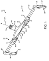
- FIGURE 1 shows an adjustable roller frame 10 that may be attached to a roller cover, such as roller cover 72 shown in FIGURE 2 , for use in rolling the roller cover 72 against a surface to be painted, treated or the like.
- the adjustable roller frame 10 can be adjusted to attach to various sized roller covers as will be discussed further below. As the use of a roller frame and roller cover is well known to those of skill in the art, further details will not be provided here.
- the adjustable roller frame 10 may include a frame 20, a pair of extension arms 30, 32, a pair of cam assemblies 40, 42, and a handle or handle attachment mechanism 60, according to one embodiment.
- the handle or handle attachment mechanism 60 may include an adjustable tool mount 62, which can attach a handle to the adjustable roller frame 10.
- the handle attachment mechanism 60 may have a handle receiving opening 70 that receives a handle (not shown).
- the handle receiving opening 70 may have a longitudinal axis OLA, as shown.
- the frame 20 may include a channel 22 that receives the extension arm 30 at one end and that receives the extension arm 32 at the other end, as shown.
- the channel 22 may have a longitudinal axis CLA. While the channel 22 may be formed in any manner chosen with the sound judgment of a person of skill in the art, for the embodiment shown, the channel 22 includes an open portion 24 in the middle of the channel 22 and a pair of enclosed or hollow portions 26, 26 on each end of the channel 22. As seen best in FIGURES 6 and 7 , a surface of the frame 20 that defines the channel 22 may have indicia 28 that indicate the various sizes of roller covers that the adjustable roller frame 10 can be adjusted to receive.
- the indicia 28 can be of any style chosen with the sound judgment of a person of skill in the art.
- the indicia 28 may include ribs 29 to indicate locations of the extension arms 30, 32 for a specific size roller cover.
- Each indicium 28 may include a symbol, character, figure, or numeral to indicate the corresponding roller cover size.
- indicia 28 may have a number (like "14") that indicates 14 inches and a juxtaposed bar that indicates precisely where the 14 inch measurement applies.
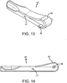
- the frame 20, as shown in FIGURES 1 and 3 may have a front wall 102 with an arched lower edge 104 and a back wall 106 with a straight lower edge 108.
- the arched lower edge 104 provides a pleasant appearance and the straight lower edge 108 provides structural rigidity.
- each extension arm 30, 32 can be identical and interchangeable.
- Each extension arm 30, 32 may have a first member 34, which slides within the channel 22.
- each extension arm 30, 32 is adjustable to accommodate different sized roller covers by sliding the first member 34 within the channel 22 differing amounts.
- FIGURE 3 shows the extension arms 30, 32 adjusted to receive a relatively larger roller cover.
- FIGURE 4 shows the extension arms 30, 32 adjusted to receive a relatively smaller roller cover.
- the first member 34 may be formed of aluminum.
- the first member 34 may have an etched powder coated baked enamel outer surface or a sandblasted outer surface to increase the friction between the first member 34 and the frame 20.
- the first member 34 may be formed of any other suitable material or combination of materials, such as another metal or plastic and its outer surface may be left untreated or may be surface treated or surface coated to increase friction by any suitable process chosen by a person of ordinary skill in the art.
- the first member 34 may have any cross-sectional shape chosen by a person of ordinary skill in the art. In one embodiment, the first member 34 has a substantially rectangular cross section. In another embodiment, shown, the first member 34 has a substantially square cross section. While the extension arms 30, 32 may be oriented in any manner chosen with the sound judgment of a person of skill in the art, for the embodiment shown the first members 54, 54 are collinear within the same linear channel 22.
- Each first member 34 may include a retaining device 35, which retains the extension arm 30, 32 within the channel 22.
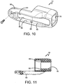
- the retaining device 35 is a fastener. In another embodiment, the retaining device 35 is a socket cap screw or socket head cap screw. In yet another embodiment, shown best in FIGURE 12 , the retaining device 35 also serves the function of holding a cap 74 to the end of the first member 34.
- the cap 74 may serve the function of providing a contact surface in case one first member 34 contacts the other - such as when both extension arms 30, 32 are pushed fully inward.
- a cap 74 may be provided on each first member 34.
- the enclosed portion 26 of the channel 22 may include a slot 27, which receives the retaining device 35 and limits the travel of the extension arm 30 outwardly.
- each extension arm 30, 32 may also have a second member 36, which extends from the first member 34 at an angle AA as shown in FIGURE 3 .
- angle AA is approximately 90 degrees.
- angle AA is between approximately 85 degrees and 95 degrees, inclusive.
- angle AA is between approximately 80 degrees and 100 degrees, inclusive.
- the second member 36 may include one or more ribs 37 to increase the strength while reducing weight.
- the second member 36 may include an attachment device 38 that is suitable to attach to a roller cover and permit the roller cover to rotate.
- the attachment device 38 is substantially cylindrical with at least two different diameter portions or steps.
- each attachment device 38 has three different diameter portions or steps 110 (see FIGURE 12 ).
- the first member 34 and the attachment device 38 may be attached to the second member 36 in any manner chosen with the sound judgment of a person of skill in the art.
- both the first member 34 and the attachment device are press fit into openings 112, 114, formed in the second member 36
- each second member 36 may have a longitudinal axis MLA.
- the two MLAs are parallel.
- the acute angle AB formed between a first plane 76 that encompasses the longitudinal axis OLA of the handle receiving opening 70 and is parallel with the longitudinal axis CLA of the channel 22 and a second plane 78 that encompasses the longitudinal axes MLA of the second members 36 and is parallel with the longitudinal axis CLA of the channel 22 is less than 40 degrees.
- the acute angle AB is less than 30 degrees.
- the acute angle AB is about 30 degrees. This acute angle AB is less than known roller frames which are typically angled at 45 degrees.
- both planes 76, 78 also encompass the longitudinal axis CLA of the channel 22.
- each cam assembly 40, 42 includes a sleeve 44 and a cam lever 46 having a cam surface 80.
- Each sleeve 44 may be attachable to an end of the frame 20 and may have an opening 50 that receives the first member 34 of the corresponding extension arm 30, 32.
- each end of the frame 20 has an extension surface 82 and a cutout 84.
- the extension surface 82 may be tubular and may define the enclosed portion 26 of the channel 22.
- the extension surface 82 may be received in the opening 50.
- Each sleeve 44 may have an extension surface 86 that is received in the cutout 84.
- the sleeve 44 may also have a shoulder 88 (see FIGURE 11 ) within the opening 50 that limits the distance the sleeve 44 can be inserted over the extension surface 82 of the frame 20.
- Each sleeve may have an aperture 90 and a cam lever receiving slot 92 defined by a pair of walls 94, 94 that face each other, as shown.
- the aperture 90 may be positioned between the walls 94, 94.
- each cam lever 46 may be moveably connected to the adjustable roller frame 10 in any manner chosen with the sound judgment of a person of skill in the art.
- Each cam lever 46 may be adjustable between: (1) an engaged position where the cam surface 80 applies a force to the first member 34 of the corresponding extension arm to prevent the first member 34 from sliding within the channel 22; and, (2) a released position where the cam surface 80 permits the first member 34 of the corresponding extension arm to slide within the channel 22.
- the cam surface 80 as well known to persons of skill in the art, is a non-uniform or uneven surface that provides cam action to the cam lever 46.
- each cam lever 46 is pivotally connected to a sleeve 44.
- each cam lever 46 pivots about a pivot pin 96 having ends that are supported to the walls 94, 94 of the sleeve 44.
- the cam lever 46 is pivoted between the engaged position and the released position by a pivot angle PA of not more than 90 degrees.
- the cam surface 80 exerts a force through the aperture 90 in the sleeve 44 onto the first member 34 of the corresponding extension arm.
- the cam lever 46 is received with the cam lever receiving slot 92.
- this distinct audible sound is not simply the typical sound of components contacting each other but is unique and dissimilar.
- this distinct audible sound is achieved by providing at least one tab 47 (for the embodiment shown, one tab 47 is provided on each side of the cam lever 46) that extends from the cam lever 46 and is received within a groove 98 formed in the adjustable roller frame 10.
- each groove 98 is formed on one of the walls 94 that define the cam lever receiving slot 92.
- each tab 47 snaps into the corresponding groove 98 thereby causing the desired distinct audible sound. It has been discovered that the tab 92 does not have to be very large to create the desired distinct audible sound. In one embodiment, the tab 92 extends from the cam lever 46 less than 0.25 inches. In another embodiment, the tab 92 extends from the cam lever 46 less than 0.125 inches.
- the cam surface 80 directly contacts the first member 34 of the corresponding extension arm.
- a component is positioned between the cam surface 80 and the first member 34. This may enhance the life of the cam surface 80.
- a projection 52 having first and second sides is pivotally attached to the frame 20 and is positioned within an aperture 100 formed in the frame 20.
- the cam surface 80 applies the force to the first side of the projection 52 which causes the second side of the projection 52 to apply the force to the first member 54 of the corresponding extension arm to prevent the first member 54 from sliding within the channel 22.
- the projection 52 and aperture 100 are positioned just below the cutout 84.
- adjustable roller frame 10 may also include a force adjustment device 48 that is adjustable to vary the amount of force applied by the cam surface 80 to the first member 54 of the corresponding extension arm when the cam lever 46 is adjusted into the engaged position.
- the force adjustment device 48 can be of any style and size chosen with the sound judgment of a person of skill in the art.
- the force adjustment device 48 adjusts the distance between the cam lever 46 and the first member 54 of the corresponding extension arm.
- the force adjustment device 48 is a mechanical connector that can be adjusted to tighten the sleeve 44 to the frame 20 (and thus decrease the distance between the sleeve 44 and the frame 20).
- the force adjustment device 48 (1) is rotatable in a first direction CW to increase the amount of force applied by the cam surface 80 to the first member 54 of the corresponding extension arm when the cam lever 46 is adjusted into the engaged position; and, (2) is rotatable in a second direction CCW to decrease the amount of force applied by the cam surface 80 to the first member 54 of the corresponding extension arm when the cam lever 46 is adjusted into the engaged position.
- the force adjustment device 48 is a threaded fastener.
- the force adjustment device 48 is a screw with a lock washer and a flat washer.
- the force adjustment device 48 can be rotated in a clockwise direction to increase the force and rotated in a counterclockwise direction to decrease the force.
- the operation of the adjustable roller frame 10 will be described.
- a particular roller cover 72 having attachment surfaces and a particular size is selected.
- the first members 54, 54 of the extension arms 30, 32 are then slid within ends of the channel 22 to accommodate the size of the roller cover as the attachment devices 38, 38 receive the attachment surfaces of the roller cover.
- the cam levers 46, 46 are then placed into their engaged positions to prevent the first members 54, 54 (and thus the extension arms 30, 32) from sliding. If the adjustable roller frame 10 is equipped with tabs 47 (or the like), this positioning of the cam levers 46, 46 into the engaged positions will create an audible sound. The user can then use the adjustable roller frame 10 and roller cover 72.
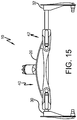
- the extension arms 30, 32 can be offset to the left or right from a centerline passing through the center of the frame 20, as shown in FIGURE 15 .
- the adjustable roller frame 10 can be disassembled as shown in FIGURE 5 for cleaning, replacement, or repair of the various components.
- the various components of the adjustable roller frame 10 can be made of any material chosen by a person of ordinary skill in the art, including, but not limited to, metal or plastic.
- the use of plastic and/or aluminum, as noted above, will advantageously reduce the weight.
Landscapes
- Engineering & Computer Science (AREA)
- Mechanical Engineering (AREA)
- Pivots And Pivotal Connections (AREA)
- Rolls And Other Rotary Bodies (AREA)
- Coating Apparatus (AREA)
- Spinning Or Twisting Of Yarns (AREA)
- Warehouses Or Storage Devices (AREA)
- Mirrors, Picture Frames, Photograph Stands, And Related Fastening Devices (AREA)
- Rehabilitation Tools (AREA)
Claims (15)
- Verstellbarer Walzenhalter, umfassend:einen Halter mit einem Kanal (22);einen ersten Verlängerungsarm (32),
umfassend: ein erstes Element, und ein zweites Element mit einer Befestigungseinrichtung, die geeignet ist, um an einer zugehörigen Walze befestigt zu werden;wobei der erste Verlängerungsarm verstellbar ist, um verschieden große Walzen aufzunehmen, indem das erste Element des ersten Verlängerungsarms verschieden weit im Kanal verschoben wird;gekennzeichnet durch eine erste Nockengruppe, umfassend: eine erste Hülse (44), die am Halter befestigt werden kann und die eine Öffnung besitzt, welche das erste Element des ersten Verlängerungsarms aufnimmt; und einen ersten Nockenhebel, der schwenkbar an der ersten Hülse befestigt ist; und eine Nockenfläche besitzt; undwobei der erste Nockenhebel schwenkbar ist zwischen: (1) einer Verriegelungsposition, bei der die erste Nockenfläche auf das erste Element des ersten Verlängerungsarms eine Kraft ausübt, um zu verhindern, dass das erste Element des ersten Verlängerungsarms sich innerhalb des Kanal verschiebt; und (2) einer Entriegelungsposition, bei der die erste Nockenfläche es ermöglicht, dass das erste Element des ersten Verlängerungsarms sich innerhalb des Kanals verschiebt. - Verstellbarer Walzenhalter nach Anspruch 1, wobei:eine erste Lasche aus dem ersten Nockenhebel um weniger als 0,25 Inch hervorsteht;der verstellbare Walzenhalter eine erste Nut besitzt; unddie erste Lasche in die erste Nut einrastet, wenn der erste Nockenhebel in die Verriegelungsposition gebracht wird, so dass ein deutlich hörbares Geräusch entsteht.
- Verstellbarer Walzenhalter nach Anspruch 2, wobei:die erste Hülse einen Nockenhebelaufnahmeschlitz umfasst, der durch erste und zweite Wände definiert wird, welche einander gegenüberliegend angeordnet sind;die erste Nut in der ersten Wand ausgebildet ist;eine zweite Nut in der zweiten Wand ausgebildet ist;die erste Lasche aus einer ersten Seite des Nockenhebels hervorsteht;eine zweite Lasche weniger als 0,25 Inch aus einer gegenüberliegenden Seite des Nockenhebels hervorsteht;die zweite Lasche in die zweite Nut einrastet, wenn der erste Nockenhebel in die Verriegelungsposition gebracht wird, so dass ein deutlich hörbares Geräusch entsteht.
- Verstellbarer Walzenhalter nach einem der Ansprüche 1 bis 3, wobei:der Halter eine Verlängerungsfläche und einen Ausschnitt umfasst;die erste Hülse eine Verlängerungsfläche umfasst, die in dem Ausschnitt aufgenommen wird; unddie Verlängerungsfläche des Halters in der Öffnung in der ersten Hülse aufgenommen wird.
- Verstellbarer Walzenhalter nach einem der Ansprüche 1 bis 4, wobei eine Oberfläche des Halters, die den Kanal definiert, Markierungen umfasst, die die Größen von zugehörigen Walzen markieren, die in dem verstellbaren Walzenhalter durch Verstellen aufgenommen werden können.
- Verstellbarer Walzenhalter nach einem der Ansprüche 1 bis 5, wobei das erste Element des ersten Verlängerungsarms aus Aluminium geformt ist und eine sandgestrahlte Oberfläche besitzt, um die Reibung zwischen dem ersten Element des ersten Verlängerungsarms und dem Halter zu erhöhen.
- Verstellbarer Walzenhalter nach einem der Ansprüche 1 bis 6, wobei:der Halter erste und zweite Enden besitzt und der Kanal erste und zweite Enden besitzt;die Befestigungseinrichtung des ersten Verlängerungsarms geeignet ist, um an einem ersten Ende der zugehörigen Walze befestigt zu werden;der erste Verlängerungsarm verstellbar ist, um Walzen verschiedener Größe aufzunehmen, indem das erste Element des ersten Verlängerungsarms verschieden weit in das erste Ende des Kanals eingeschoben wird;die erste Hülse am ersten Ende des Halters befestigt werden kann und die Öffnung in der ersten Hülse das erste Element des ersten Verlängerungsarms aufnimmt;der verstellbare Walzenhalter ferner umfasst:einen zweiten Verlängerungsarm, umfassend: ein erstes Element, und ein zweites Element mit einer Befestigungseinrichtung, die geeignet ist, um an einem zweiten Ende der zugehörigen Walze befestigt zu werden;wobei der zweite Verlängerungsarm verstellbar ist, um verschieden große Walzen aufzunehmen, indem das erste Element des zweiten Verlängerungsarms verschieden weit in das zweite Ende des Kanals eingeschoben wird;eine zweite Nockengruppe, umfassend: eine zweite Hülse, die am zweiten Ende des Halters befestigt werden kann und die eine Öffnung besitzt, welche das erste Element des zweiten Verlängerungsarms aufnimmt; und einen zweiten Nockenhebel, der schwenkbar an der zweiten Hülse befestigt ist; und eine Nockenfläche besitzt;wobei der zweite Nockenhebel schwenkbar ist zwischen: (1) einer Verriegelungsposition, bei der die zweite Nockenfläche auf das erste Element des zweiten Verlängerungsarms eine Kraft ausübt, um zu verhindern, dass das erste Element des zweiten Verlängerungsarms sich innerhalb des Kanal verschiebt; und (2) einer Entriegelungsposition, bei der die zweite Nockenfläche es ermöglicht, dass das erste Element des zweiten Verlängerungsarms sich innerhalb des Kanals verschiebt; undwobei der Halter eine vordere Wand mit einer gewölbten Unterkante und eine hintere Wand mit einer geraden Unterkante besitzt.
- Verstellbarer Walzenhalter nach einem der Ansprüche 1 bis 7, ferner umfassend:
eine erste Krafteinstelleinrichtung, die einstellbar ist, um die Kraftmenge zu variieren, die durch die erste Nockenfläche auf das erste Element des ersten Verlängerungsarms ausgeübt wird, wenn der erste Nockenhebel in die Verriegelungsposition gebracht wird. - Verstellbarer Walzenhalter nach Anspruch 8, wobei die erste Krafteinstelleinrichtung den Abstand zwischen dem ersten Nockenhebel und dem ersten Element des ersten Verlängerungsarms einstellt.
- Verstellbarer Walzenhalter nach Anspruch 8 oder 9, wobei die erste Krafteinstelleinrichtung: (1) in einer ersten Richtung drehbar ist, um die Kraftmenge, die durch die erste Nockenfläche auf das erste Element des ersten Verlängerungsarms ausgeübt wird, wenn der erste Nockenhebel in die Verriegelungsposition gebracht wird, zu erhöhen; und (2) in einer zweiten Richtung drehbar ist, um die Kraftmenge, die durch die erste Nockenfläche auf das erste Element des ersten Verlängerungsarms ausgeübt wird, wenn der erste Nockenhebel in die Verriegelungsposition gebracht wird, zu verringern.
- Verstellbarer Walzenhalter nach einem der Ansprüche 1 bis 10, wobei:
ein Vorsprung mit ersten und zweiten Seiten schwenkbar am Halter befestigt ist; und wenn der erste Nockenhebel sich in der Verriegelungsposition befindet, die erste Nockenfläche die Kraft auf die erste Seite des Vorsprungs ausübt, was dazu führt, dass die zweite Seite des Vorsprungs die Kraft auf das erste Element des ersten Verlängerungsarms ausübt, um zu verhindern, dass das erste Element des ersten Verlängerungsarms sich innerhalb des Kanals verschiebt. - Verstellbarer Walzenhalter nach einem der Ansprüche 1 bis 11, wobei der erste Nockenhebel zwischen der Verriegelungsposition und der Entriegelungsposition um einen Schwenkwinkel von nicht mehr als 90 Grad schwenkbar ist.
- Verstellbarer Walzenhalter nach einem der Ansprüche 8 bis 12, wobei:der Kanal erste und zweite Enden besitzt;die Befestigungseinrichtung des ersten Verlängerungsarms geeignet ist, um an einem ersten Ende der zugehörigen Walze befestigt zu werden;der erste Verlängerungsarm verstellbar ist, um verschieden große Walzen aufzunehmen, indem das erste Element des ersten Verlängerungsarms verschieden weit in das erste Ende des Kanals eingeschoben wird;der verstellbare Walzenhalter ferner umfasst:einen zweiten Verlängerungsarm, umfassend: ein erstes Element, und ein zweites Element mit einer Befestigungseinrichtung, die geeignet ist, um an einem zweiten Ende der zugehörigen Walze befestigt zu werden;wobei der zweite Verlängerungsarm verstellbar ist, um verschieden große Walzen aufzunehmen, indem das erste Element des zweiten Verlängerungsarms verschieden weit in das zweite Ende des Kanals eingeschoben wird;eine zweite Nockengruppe, umfassend: einen zweiten Nockenhebel mit einer zweiten Nockenhebeloberfläche;wobei der zweite Nockenhebel schwenkbar ist zwischen: (1) einer Verriegelungsposition, bei der die zweite Nockenfläche auf das erste Element des zweiten Verlängerungsarms eine Kraft ausübt, um zu verhindern, dass das erste Element des zweiten Verlängerungsarms sich innerhalb des Kanal verschiebt; und (2) einer Entriegelungsposition, bei der die zweite Nockenfläche es ermöglicht, dass das erste Element des zweiten Verlängerungsarms sich innerhalb des Kanals verschiebt; undeine zweite Krafteinstelleinrichtung, die einstellbar ist, um die Kraftmenge zu variieren, die durch die zweite Nockenfläche auf das erste Element des zweiten Verlängerungsarms ausgeübt wird, wenn der zweite Nockenhebel in die Verriegelungsposition gebracht wird; undjede Befestigungseinrichtung im Wesentlichen zylindrisch ist mit wenigstens zwei Bereichen unterschiedlichen Durchmessers.
- Verstellbarer Walzenhalter nach einem der Ansprüche 1 bis 13, wobei:der Kanal erste und zweie Enden besitzt;die Befestigungseinrichtung des ersten Verlängerungsarms geeignet ist, um an einem ersten Ende der zugehörigen Walze befestigt zu werden;der erste Verlängerungsarm verstellbar ist, um verschieden große Walzen aufzunehmen, indem das erste Element des ersten Verlängerungsarms verschieden weit in das erste Ende des Kanals eingeschoben wird;der verstellbare Walzenhalter ferner umfasst:einen zweiten Verlängerungsarm, umfassend: ein erstes Element, und ein zweites Element mit einer Befestigungseinrichtung, die geeignet ist, um an einem zweiten Ende der zugehörigen Walze befestigt zu werden;wobei der zweite Verlängerungsarm verstellbar ist, um verschieden große Walzen aufzunehmen, indem das erste Element des zweiten Verlängerungsarms verschieden weit in das zweite Ende des Kanals eingeschoben wird;eine zweite Nockengruppe, umfassend: einen zweiten Nockenhebel mit einer zweiten Nockenfläche;wobei der zweite Nockenhebel schwenkbar ist zwischen: (1) einer Verriegelungsposition, bei der die zweite Nockenfläche auf das erste Element des zweiten Verlängerungsarms eine Kraft ausübt, um zu verhindern, dass das erste Element des zweiten Verlängerungsarms sich innerhalb des Kanal verschiebt; und (2) einer Entriegelungsposition, bei der die zweite Nockenfläche es ermöglicht, dass das erste Element des zweiten Verlängerungsarms sich innerhalb des Kanals verschiebt;der Kanal eine Längsachse besitzt;der verstellbare Walzenhalter ferner einen Griffbefestigungsmechanismus mit einer Griffaufnahmeöffnung mit einer Längsachse besitzt;die zweiten Elemente jeweils eine Längsachse besitzen;der zwischen einer ersten Ebene, die die Längsachse der Griffaufnahmeöffnung umfasst und parallel zur Längsachse des Kanals verläuft, und einer zweiten Ebene, die die Längsachsen der zweiten Elemente umfasst und parallel zur Längsachse des Kanals verläuft, gebildete spitze Winkel weniger als 40 Grad beträgt.
- Verstellbarer Walzenhalter nach einem der Ansprüche 1 bis 14, wobei:der Kanal erste und zweite Enden besitzt; unddie ersten Elemente kollinear sind.
Applications Claiming Priority (2)
| Application Number | Priority Date | Filing Date | Title |
|---|---|---|---|
| US35874810P | 2010-06-25 | 2010-06-25 | |
| PCT/US2011/001136 WO2011162827A1 (en) | 2010-06-25 | 2011-06-24 | Adjustable roller frame |
Publications (2)
| Publication Number | Publication Date |
|---|---|
| EP2585225A1 EP2585225A1 (de) | 2013-05-01 |
| EP2585225B1 true EP2585225B1 (de) | 2018-05-30 |
Family
ID=44628472
Family Applications (1)
| Application Number | Title | Priority Date | Filing Date |
|---|---|---|---|
| EP11732529.0A Active EP2585225B1 (de) | 2010-06-25 | 2011-06-24 | Einstellbarer rollenkäfig |
Country Status (9)
| Country | Link |
|---|---|
| US (3) | US8671501B2 (de) |
| EP (1) | EP2585225B1 (de) |
| CN (2) | CN105728258B (de) |
| AU (1) | AU2011269781B2 (de) |
| BR (1) | BR112012032732B1 (de) |
| CA (1) | CA2803112C (de) |
| CL (1) | CL2012003598A1 (de) |
| MX (1) | MX2012014761A (de) |
| WO (1) | WO2011162827A1 (de) |
Families Citing this family (11)
| Publication number | Priority date | Publication date | Assignee | Title |
|---|---|---|---|---|
| US8910339B1 (en) * | 2013-08-21 | 2014-12-16 | Ruben DeLeon | Paint roller assembly |
| CL2015000871S1 (es) | 2014-10-07 | 2015-10-30 | Sherwin Williams Co | Pieza de rodillo |
| US11207767B2 (en) | 2015-07-28 | 2021-12-28 | Caterpillar Energy Solutions Gmbh | Screw tensioning device |
| US10279370B2 (en) * | 2017-04-21 | 2019-05-07 | A. Richard Tools Co./Outils A. Richard Co. | Paint roller frame |
| CN109453963B (zh) * | 2018-10-31 | 2021-02-02 | 沪东中华造船(集团)有限公司 | 涂装预涂修补变形油漆滚筒装置及其使用方法 |
| CN212105008U (zh) * | 2020-04-29 | 2020-12-08 | 杭州小畅快进出口有限公司 | 滚筒刷夹持装置及滚筒刷 |
| USD924570S1 (en) | 2020-06-19 | 2021-07-13 | William John Winter | Adjustable roller assembly for micro foam covers |
| JP7641043B2 (ja) * | 2020-08-04 | 2025-03-06 | エム. シャネイ,デイビッド | 塗料ローラアセンブリ |
| WO2022192226A1 (en) | 2021-03-08 | 2022-09-15 | Swimc Llc | Application apparatus for a coatings material |
| KR102428690B1 (ko) * | 2021-05-03 | 2022-08-03 | 주식회사 케이씨씨 | 도장 롤러 |
| US12115553B2 (en) * | 2021-05-13 | 2024-10-15 | Melanie Hepler | 180 degree pivotable and telescoping paint roller frame |
Citations (1)
| Publication number | Priority date | Publication date | Assignee | Title |
|---|---|---|---|---|
| EP1264641A2 (de) * | 2001-06-07 | 2002-12-11 | Robert D. Newman | Farbrollerrahmen mit schaltbarem Arm |
Family Cites Families (15)
| Publication number | Priority date | Publication date | Assignee | Title |
|---|---|---|---|---|
| US2970366A (en) | 1958-03-18 | 1961-02-07 | Frank W Gill | Extensible paint roller core |
| US3310831A (en) | 1965-06-01 | 1967-03-28 | William J Brinker | Paint applying roller |
| US3604046A (en) | 1969-05-28 | 1971-09-14 | Harold J Taylor | Expansible paint applicator |
| US3593361A (en) * | 1969-06-09 | 1971-07-20 | David I Welt | Adjustable paint-roller holder |
| US3745624A (en) | 1972-01-27 | 1973-07-17 | R Newman | Extensible paint roller frame |
| US4868946A (en) * | 1988-10-14 | 1989-09-26 | The Wooster Brush Company | Adjustable roller frame |
| USD332009S (en) | 1990-07-12 | 1992-12-29 | Kiefer Brushes, Inc. | Adjustable frame for supporting a roller for applying coatings |
| US5288161A (en) | 1992-02-14 | 1994-02-22 | The Wooster Brush Company | Quick release lock mechanisms |
| US5921905A (en) | 1996-10-21 | 1999-07-13 | Robert D. Newman, Sr. | Adjustable roller holder with rack and pinion gear mechanism |
| US5806131A (en) | 1997-05-27 | 1998-09-15 | The Wooster Brush Company | Plastic paint roller frame |
| DE10319658B3 (de) * | 2003-05-02 | 2004-12-16 | Windmöller & Hölscher Kg | Klebstoffübertragungswalze einer Klebstoffauftragsvorrichtung |
| CN2657795Y (zh) * | 2003-11-03 | 2004-11-24 | 卢伟明 | 可调滚刷架 |
| CN201086057Y (zh) * | 2007-05-11 | 2008-07-16 | 宁波捷利工具有限公司 | 可伸缩的涂刷滚筒架 |
| US7784142B2 (en) * | 2007-09-10 | 2010-08-31 | The Wooster Brush Company | Adjustable roller frame |
| US9027189B2 (en) * | 2012-12-19 | 2015-05-12 | Agri-Fab, Inc. | Brush height setting assembly and method |
-
2011
- 2011-06-24 WO PCT/US2011/001136 patent/WO2011162827A1/en not_active Ceased
- 2011-06-24 CA CA2803112A patent/CA2803112C/en active Active
- 2011-06-24 AU AU2011269781A patent/AU2011269781B2/en active Active
- 2011-06-24 CN CN201610221200.9A patent/CN105728258B/zh active Active
- 2011-06-24 CN CN201180030020.8A patent/CN103189148B/zh active Active
- 2011-06-24 EP EP11732529.0A patent/EP2585225B1/de active Active
- 2011-06-24 BR BR112012032732-1A patent/BR112012032732B1/pt active IP Right Grant
- 2011-06-24 MX MX2012014761A patent/MX2012014761A/es active IP Right Grant
- 2011-06-24 US US13/168,100 patent/US8671501B2/en active Active
-
2012
- 2012-12-20 CL CL2012003598A patent/CL2012003598A1/es unknown
-
2014
- 2014-02-18 US US14/182,813 patent/US20140157540A1/en not_active Abandoned
- 2014-10-21 US US14/519,781 patent/US9339841B2/en active Active
Patent Citations (1)
| Publication number | Priority date | Publication date | Assignee | Title |
|---|---|---|---|---|
| EP1264641A2 (de) * | 2001-06-07 | 2002-12-11 | Robert D. Newman | Farbrollerrahmen mit schaltbarem Arm |
Also Published As
| Publication number | Publication date |
|---|---|
| US9339841B2 (en) | 2016-05-17 |
| AU2011269781B2 (en) | 2015-04-02 |
| CN105728258B (zh) | 2018-11-09 |
| US20150038308A1 (en) | 2015-02-05 |
| BR112012032732A2 (pt) | 2016-11-08 |
| EP2585225A1 (de) | 2013-05-01 |
| CA2803112A1 (en) | 2011-12-29 |
| CN103189148B (zh) | 2016-05-11 |
| WO2011162827A1 (en) | 2011-12-29 |
| CA2803112C (en) | 2015-09-01 |
| CL2012003598A1 (es) | 2014-02-14 |
| US20120117742A1 (en) | 2012-05-17 |
| US8671501B2 (en) | 2014-03-18 |
| MX2012014761A (es) | 2013-12-02 |
| BR112012032732B1 (pt) | 2021-01-19 |
| AU2011269781A1 (en) | 2013-01-10 |
| CN103189148A (zh) | 2013-07-03 |
| CN105728258A (zh) | 2016-07-06 |
| US20140157540A1 (en) | 2014-06-12 |
Similar Documents
| Publication | Publication Date | Title |
|---|---|---|
| EP2585225B1 (de) | Einstellbarer rollenkäfig | |
| US7784142B2 (en) | Adjustable roller frame | |
| US20190112850A1 (en) | Holder for a door or casement | |
| US10533326B2 (en) | Plaster taping apparatus and attachments | |
| US9649656B2 (en) | Paint roller handle | |
| WO2007076142A9 (en) | Multi paint roller connector | |
| US6045282A (en) | Multi-roller paint applicator system | |
| AU2015202711B2 (en) | Adjustable roller frame | |
| US8365342B2 (en) | Combination paint roller, paint tray and stencil tube | |
| US8915209B2 (en) | Paint roller with an end-surface blocking structure | |
| JP2020049415A (ja) | 外壁材塗装装置 | |
| US7984808B1 (en) | Rolling painting frame | |
| US20150196932A1 (en) | Epoxy and Paint Roller | |
| CN202087495U (zh) | 油漆刷 | |
| US7451518B1 (en) | Multi-roller applicator for painting | |
| US20170087583A1 (en) | Spatial Control Apparatus for Painting | |
| US20070266513A1 (en) | Dual mode paint roller | |
| CN219648012U (zh) | 一种油漆滚架 | |
| US20180125309A1 (en) | Retrofit Rapid Change Toilet Paper Dispenser | |
| CN204717265U (zh) | 一种平台角度调节装置 | |
| CN213898008U (zh) | 一种滚筒刷 | |
| TWI448332B (zh) | 具有側邊阻隔片的滾輪式油漆刷結構改良 | |
| US20070108337A1 (en) | System for dispensing tape | |
| KR20180000935A (ko) | 그립의 각도 조절이 가능한 테이프 디스펜서 | |
| HK1074732A2 (en) | Pushbutton controlled correction tape |
Legal Events
| Date | Code | Title | Description |
|---|---|---|---|
| PUAI | Public reference made under article 153(3) epc to a published international application that has entered the european phase |
Free format text: ORIGINAL CODE: 0009012 |
|
| 17P | Request for examination filed |
Effective date: 20130122 |
|
| AK | Designated contracting states |
Kind code of ref document: A1 Designated state(s): AL AT BE BG CH CY CZ DE DK EE ES FI FR GB GR HR HU IE IS IT LI LT LU LV MC MK MT NL NO PL PT RO RS SE SI SK SM TR |
|
| DAX | Request for extension of the european patent (deleted) | ||
| GRAP | Despatch of communication of intention to grant a patent |
Free format text: ORIGINAL CODE: EPIDOSNIGR1 |
|
| STAA | Information on the status of an ep patent application or granted ep patent |
Free format text: STATUS: GRANT OF PATENT IS INTENDED |
|
| INTG | Intention to grant announced |
Effective date: 20180105 |
|
| RIN1 | Information on inventor provided before grant (corrected) |
Inventor name: ANDERSON, SARA-JANE, A. Inventor name: BUCKEL, JR., CHARLES, T. Inventor name: WALTERS, RICHARD, S. Inventor name: SCHMITZ, DAVID Inventor name: LAMBERTSON, JR., MICHAEL, C. Inventor name: MARSDEN, ANDREW, K. |
|
| GRAS | Grant fee paid |
Free format text: ORIGINAL CODE: EPIDOSNIGR3 |
|
| GRAA | (expected) grant |
Free format text: ORIGINAL CODE: 0009210 |
|
| STAA | Information on the status of an ep patent application or granted ep patent |
Free format text: STATUS: THE PATENT HAS BEEN GRANTED |
|
| AK | Designated contracting states |
Kind code of ref document: B1 Designated state(s): AL AT BE BG CH CY CZ DE DK EE ES FI FR GB GR HR HU IE IS IT LI LT LU LV MC MK MT NL NO PL PT RO RS SE SI SK SM TR |
|
| REG | Reference to a national code |
Ref country code: GB Ref legal event code: FG4D |
|
| REG | Reference to a national code |
Ref country code: CH Ref legal event code: EP |
|
| REG | Reference to a national code |
Ref country code: AT Ref legal event code: REF Ref document number: 1003086 Country of ref document: AT Kind code of ref document: T Effective date: 20180615 |
|
| REG | Reference to a national code |
Ref country code: FR Ref legal event code: PLFP Year of fee payment: 8 |
|
| REG | Reference to a national code |
Ref country code: IE Ref legal event code: FG4D |
|
| REG | Reference to a national code |
Ref country code: DE Ref legal event code: R096 Ref document number: 602011048787 Country of ref document: DE |
|
| REG | Reference to a national code |
Ref country code: NL Ref legal event code: MP Effective date: 20180530 |
|
| REG | Reference to a national code |
Ref country code: LT Ref legal event code: MG4D |
|
| PG25 | Lapsed in a contracting state [announced via postgrant information from national office to epo] |
Ref country code: FI Free format text: LAPSE BECAUSE OF FAILURE TO SUBMIT A TRANSLATION OF THE DESCRIPTION OR TO PAY THE FEE WITHIN THE PRESCRIBED TIME-LIMIT Effective date: 20180530 Ref country code: BG Free format text: LAPSE BECAUSE OF FAILURE TO SUBMIT A TRANSLATION OF THE DESCRIPTION OR TO PAY THE FEE WITHIN THE PRESCRIBED TIME-LIMIT Effective date: 20180830 Ref country code: NO Free format text: LAPSE BECAUSE OF FAILURE TO SUBMIT A TRANSLATION OF THE DESCRIPTION OR TO PAY THE FEE WITHIN THE PRESCRIBED TIME-LIMIT Effective date: 20180830 Ref country code: CY Free format text: LAPSE BECAUSE OF FAILURE TO SUBMIT A TRANSLATION OF THE DESCRIPTION OR TO PAY THE FEE WITHIN THE PRESCRIBED TIME-LIMIT Effective date: 20180530 Ref country code: ES Free format text: LAPSE BECAUSE OF FAILURE TO SUBMIT A TRANSLATION OF THE DESCRIPTION OR TO PAY THE FEE WITHIN THE PRESCRIBED TIME-LIMIT Effective date: 20180530 Ref country code: SE Free format text: LAPSE BECAUSE OF FAILURE TO SUBMIT A TRANSLATION OF THE DESCRIPTION OR TO PAY THE FEE WITHIN THE PRESCRIBED TIME-LIMIT Effective date: 20180530 Ref country code: LT Free format text: LAPSE BECAUSE OF FAILURE TO SUBMIT A TRANSLATION OF THE DESCRIPTION OR TO PAY THE FEE WITHIN THE PRESCRIBED TIME-LIMIT Effective date: 20180530 |
|
| RAP2 | Party data changed (patent owner data changed or rights of a patent transferred) |
Owner name: THE SHERWIN-WILLIAMS HEADQUARTERS COMPANY |
|
| RAP2 | Party data changed (patent owner data changed or rights of a patent transferred) |
Owner name: SWIMC LLC |
|
| PG25 | Lapsed in a contracting state [announced via postgrant information from national office to epo] |
Ref country code: LV Free format text: LAPSE BECAUSE OF FAILURE TO SUBMIT A TRANSLATION OF THE DESCRIPTION OR TO PAY THE FEE WITHIN THE PRESCRIBED TIME-LIMIT Effective date: 20180530 Ref country code: GR Free format text: LAPSE BECAUSE OF FAILURE TO SUBMIT A TRANSLATION OF THE DESCRIPTION OR TO PAY THE FEE WITHIN THE PRESCRIBED TIME-LIMIT Effective date: 20180831 Ref country code: HR Free format text: LAPSE BECAUSE OF FAILURE TO SUBMIT A TRANSLATION OF THE DESCRIPTION OR TO PAY THE FEE WITHIN THE PRESCRIBED TIME-LIMIT Effective date: 20180530 Ref country code: RS Free format text: LAPSE BECAUSE OF FAILURE TO SUBMIT A TRANSLATION OF THE DESCRIPTION OR TO PAY THE FEE WITHIN THE PRESCRIBED TIME-LIMIT Effective date: 20180530 |
|
| REG | Reference to a national code |
Ref country code: AT Ref legal event code: MK05 Ref document number: 1003086 Country of ref document: AT Kind code of ref document: T Effective date: 20180530 |
|
| PG25 | Lapsed in a contracting state [announced via postgrant information from national office to epo] |
Ref country code: NL Free format text: LAPSE BECAUSE OF FAILURE TO SUBMIT A TRANSLATION OF THE DESCRIPTION OR TO PAY THE FEE WITHIN THE PRESCRIBED TIME-LIMIT Effective date: 20180530 |
|
| PG25 | Lapsed in a contracting state [announced via postgrant information from national office to epo] |
Ref country code: PL Free format text: LAPSE BECAUSE OF FAILURE TO SUBMIT A TRANSLATION OF THE DESCRIPTION OR TO PAY THE FEE WITHIN THE PRESCRIBED TIME-LIMIT Effective date: 20180530 Ref country code: DK Free format text: LAPSE BECAUSE OF FAILURE TO SUBMIT A TRANSLATION OF THE DESCRIPTION OR TO PAY THE FEE WITHIN THE PRESCRIBED TIME-LIMIT Effective date: 20180530 Ref country code: AT Free format text: LAPSE BECAUSE OF FAILURE TO SUBMIT A TRANSLATION OF THE DESCRIPTION OR TO PAY THE FEE WITHIN THE PRESCRIBED TIME-LIMIT Effective date: 20180530 Ref country code: EE Free format text: LAPSE BECAUSE OF FAILURE TO SUBMIT A TRANSLATION OF THE DESCRIPTION OR TO PAY THE FEE WITHIN THE PRESCRIBED TIME-LIMIT Effective date: 20180530 Ref country code: RO Free format text: LAPSE BECAUSE OF FAILURE TO SUBMIT A TRANSLATION OF THE DESCRIPTION OR TO PAY THE FEE WITHIN THE PRESCRIBED TIME-LIMIT Effective date: 20180530 Ref country code: CZ Free format text: LAPSE BECAUSE OF FAILURE TO SUBMIT A TRANSLATION OF THE DESCRIPTION OR TO PAY THE FEE WITHIN THE PRESCRIBED TIME-LIMIT Effective date: 20180530 Ref country code: SK Free format text: LAPSE BECAUSE OF FAILURE TO SUBMIT A TRANSLATION OF THE DESCRIPTION OR TO PAY THE FEE WITHIN THE PRESCRIBED TIME-LIMIT Effective date: 20180530 |
|
| REG | Reference to a national code |
Ref country code: CH Ref legal event code: PL |
|
| PG25 | Lapsed in a contracting state [announced via postgrant information from national office to epo] |
Ref country code: SM Free format text: LAPSE BECAUSE OF FAILURE TO SUBMIT A TRANSLATION OF THE DESCRIPTION OR TO PAY THE FEE WITHIN THE PRESCRIBED TIME-LIMIT Effective date: 20180530 Ref country code: IT Free format text: LAPSE BECAUSE OF FAILURE TO SUBMIT A TRANSLATION OF THE DESCRIPTION OR TO PAY THE FEE WITHIN THE PRESCRIBED TIME-LIMIT Effective date: 20180530 |
|
| REG | Reference to a national code |
Ref country code: DE Ref legal event code: R097 Ref document number: 602011048787 Country of ref document: DE |
|
| REG | Reference to a national code |
Ref country code: BE Ref legal event code: MM Effective date: 20180630 |
|
| REG | Reference to a national code |
Ref country code: IE Ref legal event code: MM4A |
|
| PG25 | Lapsed in a contracting state [announced via postgrant information from national office to epo] |
Ref country code: MC Free format text: LAPSE BECAUSE OF FAILURE TO SUBMIT A TRANSLATION OF THE DESCRIPTION OR TO PAY THE FEE WITHIN THE PRESCRIBED TIME-LIMIT Effective date: 20180530 Ref country code: LU Free format text: LAPSE BECAUSE OF NON-PAYMENT OF DUE FEES Effective date: 20180624 |
|
| PLBE | No opposition filed within time limit |
Free format text: ORIGINAL CODE: 0009261 |
|
| STAA | Information on the status of an ep patent application or granted ep patent |
Free format text: STATUS: NO OPPOSITION FILED WITHIN TIME LIMIT |
|
| PG25 | Lapsed in a contracting state [announced via postgrant information from national office to epo] |
Ref country code: IE Free format text: LAPSE BECAUSE OF NON-PAYMENT OF DUE FEES Effective date: 20180624 Ref country code: LI Free format text: LAPSE BECAUSE OF NON-PAYMENT OF DUE FEES Effective date: 20180630 Ref country code: CH Free format text: LAPSE BECAUSE OF NON-PAYMENT OF DUE FEES Effective date: 20180630 |
|
| 26N | No opposition filed |
Effective date: 20190301 |
|
| PG25 | Lapsed in a contracting state [announced via postgrant information from national office to epo] |
Ref country code: BE Free format text: LAPSE BECAUSE OF NON-PAYMENT OF DUE FEES Effective date: 20180630 Ref country code: SI Free format text: LAPSE BECAUSE OF FAILURE TO SUBMIT A TRANSLATION OF THE DESCRIPTION OR TO PAY THE FEE WITHIN THE PRESCRIBED TIME-LIMIT Effective date: 20180530 |
|
| PG25 | Lapsed in a contracting state [announced via postgrant information from national office to epo] |
Ref country code: AL Free format text: LAPSE BECAUSE OF FAILURE TO SUBMIT A TRANSLATION OF THE DESCRIPTION OR TO PAY THE FEE WITHIN THE PRESCRIBED TIME-LIMIT Effective date: 20180530 |
|
| PG25 | Lapsed in a contracting state [announced via postgrant information from national office to epo] |
Ref country code: MT Free format text: LAPSE BECAUSE OF NON-PAYMENT OF DUE FEES Effective date: 20180624 |
|
| PG25 | Lapsed in a contracting state [announced via postgrant information from national office to epo] |
Ref country code: TR Free format text: LAPSE BECAUSE OF FAILURE TO SUBMIT A TRANSLATION OF THE DESCRIPTION OR TO PAY THE FEE WITHIN THE PRESCRIBED TIME-LIMIT Effective date: 20180530 |
|
| PG25 | Lapsed in a contracting state [announced via postgrant information from national office to epo] |
Ref country code: PT Free format text: LAPSE BECAUSE OF FAILURE TO SUBMIT A TRANSLATION OF THE DESCRIPTION OR TO PAY THE FEE WITHIN THE PRESCRIBED TIME-LIMIT Effective date: 20180530 Ref country code: HU Free format text: LAPSE BECAUSE OF FAILURE TO SUBMIT A TRANSLATION OF THE DESCRIPTION OR TO PAY THE FEE WITHIN THE PRESCRIBED TIME-LIMIT; INVALID AB INITIO Effective date: 20110624 |
|
| PG25 | Lapsed in a contracting state [announced via postgrant information from national office to epo] |
Ref country code: MK Free format text: LAPSE BECAUSE OF NON-PAYMENT OF DUE FEES Effective date: 20180530 |
|
| PG25 | Lapsed in a contracting state [announced via postgrant information from national office to epo] |
Ref country code: IS Free format text: LAPSE BECAUSE OF FAILURE TO SUBMIT A TRANSLATION OF THE DESCRIPTION OR TO PAY THE FEE WITHIN THE PRESCRIBED TIME-LIMIT Effective date: 20180930 |
|
| P01 | Opt-out of the competence of the unified patent court (upc) registered |
Effective date: 20230601 |
|
| PGFP | Annual fee paid to national office [announced via postgrant information from national office to epo] |
Ref country code: DE Payment date: 20250626 Year of fee payment: 15 |
|
| PGFP | Annual fee paid to national office [announced via postgrant information from national office to epo] |
Ref country code: GB Payment date: 20250617 Year of fee payment: 15 |
|
| PGFP | Annual fee paid to national office [announced via postgrant information from national office to epo] |
Ref country code: FR Payment date: 20250624 Year of fee payment: 15 |