EP2584971B1 - Ultraschallbildgebung mit analogverarbeitung - Google Patents
Ultraschallbildgebung mit analogverarbeitung Download PDFInfo
- Publication number
- EP2584971B1 EP2584971B1 EP11798920.2A EP11798920A EP2584971B1 EP 2584971 B1 EP2584971 B1 EP 2584971B1 EP 11798920 A EP11798920 A EP 11798920A EP 2584971 B1 EP2584971 B1 EP 2584971B1
- Authority
- EP
- European Patent Office
- Prior art keywords
- signal
- processing
- signals
- ultrasound
- input
- Prior art date
- Legal status (The legal status is an assumption and is not a legal conclusion. Google has not performed a legal analysis and makes no representation as to the accuracy of the status listed.)
- Active
Links
- 238000012545 processing Methods 0.000 title claims description 132
- 238000012285 ultrasound imaging Methods 0.000 title description 4
- 239000000523 sample Substances 0.000 claims description 49
- 238000002604 ultrasonography Methods 0.000 claims description 46
- 239000003990 capacitor Substances 0.000 claims description 24
- 230000001934 delay Effects 0.000 claims description 19
- 238000005070 sampling Methods 0.000 claims description 16
- 238000000034 method Methods 0.000 claims description 15
- 238000004891 communication Methods 0.000 claims description 8
- 238000012546 transfer Methods 0.000 claims description 5
- 230000004044 response Effects 0.000 claims description 4
- 238000012163 sequencing technique Methods 0.000 claims description 3
- 238000013459 approach Methods 0.000 description 11
- 238000003384 imaging method Methods 0.000 description 11
- 230000006870 function Effects 0.000 description 6
- 230000005284 excitation Effects 0.000 description 5
- 238000001914 filtration Methods 0.000 description 5
- 239000011159 matrix material Substances 0.000 description 5
- 230000003321 amplification Effects 0.000 description 4
- 230000008901 benefit Effects 0.000 description 4
- 239000004020 conductor Substances 0.000 description 4
- 230000003111 delayed effect Effects 0.000 description 4
- 238000003199 nucleic acid amplification method Methods 0.000 description 4
- 230000008569 process Effects 0.000 description 4
- 230000005540 biological transmission Effects 0.000 description 3
- 238000006243 chemical reaction Methods 0.000 description 3
- 238000001514 detection method Methods 0.000 description 3
- 238000010586 diagram Methods 0.000 description 3
- 238000003491 array Methods 0.000 description 2
- 238000002059 diagnostic imaging Methods 0.000 description 2
- 238000002493 microarray Methods 0.000 description 2
- 238000012935 Averaging Methods 0.000 description 1
- 230000006978 adaptation Effects 0.000 description 1
- 238000004458 analytical method Methods 0.000 description 1
- 238000013476 bayesian approach Methods 0.000 description 1
- 230000015572 biosynthetic process Effects 0.000 description 1
- 230000006835 compression Effects 0.000 description 1
- 238000007906 compression Methods 0.000 description 1
- 230000008878 coupling Effects 0.000 description 1
- 238000010168 coupling process Methods 0.000 description 1
- 238000005859 coupling reaction Methods 0.000 description 1
- 238000011161 development Methods 0.000 description 1
- 239000006185 dispersion Substances 0.000 description 1
- 230000000694 effects Effects 0.000 description 1
- 238000009499 grossing Methods 0.000 description 1
- 230000006872 improvement Effects 0.000 description 1
- 238000005457 optimization Methods 0.000 description 1
- 230000009467 reduction Effects 0.000 description 1
- 230000035945 sensitivity Effects 0.000 description 1
- 230000008054 signal transmission Effects 0.000 description 1
- 230000009466 transformation Effects 0.000 description 1
- 238000004148 unit process Methods 0.000 description 1
Images

Classifications
-
- A—HUMAN NECESSITIES
- A61—MEDICAL OR VETERINARY SCIENCE; HYGIENE
- A61B—DIAGNOSIS; SURGERY; IDENTIFICATION
- A61B8/00—Diagnosis using ultrasonic, sonic or infrasonic waves
- A61B8/44—Constructional features of the ultrasonic, sonic or infrasonic diagnostic device
- A61B8/4444—Constructional features of the ultrasonic, sonic or infrasonic diagnostic device related to the probe
-
- A—HUMAN NECESSITIES
- A61—MEDICAL OR VETERINARY SCIENCE; HYGIENE
- A61B—DIAGNOSIS; SURGERY; IDENTIFICATION
- A61B8/00—Diagnosis using ultrasonic, sonic or infrasonic waves
- A61B8/54—Control of the diagnostic device
-
- G—PHYSICS
- G01—MEASURING; TESTING
- G01S—RADIO DIRECTION-FINDING; RADIO NAVIGATION; DETERMINING DISTANCE OR VELOCITY BY USE OF RADIO WAVES; LOCATING OR PRESENCE-DETECTING BY USE OF THE REFLECTION OR RERADIATION OF RADIO WAVES; ANALOGOUS ARRANGEMENTS USING OTHER WAVES
- G01S15/00—Systems using the reflection or reradiation of acoustic waves, e.g. sonar systems
- G01S15/88—Sonar systems specially adapted for specific applications
- G01S15/89—Sonar systems specially adapted for specific applications for mapping or imaging
- G01S15/8906—Short-range imaging systems; Acoustic microscope systems using pulse-echo techniques
- G01S15/8909—Short-range imaging systems; Acoustic microscope systems using pulse-echo techniques using a static transducer configuration
- G01S15/8915—Short-range imaging systems; Acoustic microscope systems using pulse-echo techniques using a static transducer configuration using a transducer array
- G01S15/8927—Short-range imaging systems; Acoustic microscope systems using pulse-echo techniques using a static transducer configuration using a transducer array using simultaneously or sequentially two or more subarrays or subapertures
-
- G—PHYSICS
- G01—MEASURING; TESTING
- G01S—RADIO DIRECTION-FINDING; RADIO NAVIGATION; DETERMINING DISTANCE OR VELOCITY BY USE OF RADIO WAVES; LOCATING OR PRESENCE-DETECTING BY USE OF THE REFLECTION OR RERADIATION OF RADIO WAVES; ANALOGOUS ARRANGEMENTS USING OTHER WAVES
- G01S7/00—Details of systems according to groups G01S13/00, G01S15/00, G01S17/00
- G01S7/52—Details of systems according to groups G01S13/00, G01S15/00, G01S17/00 of systems according to group G01S15/00
- G01S7/52017—Details of systems according to groups G01S13/00, G01S15/00, G01S17/00 of systems according to group G01S15/00 particularly adapted to short-range imaging
- G01S7/52019—Details of transmitters
- G01S7/5202—Details of transmitters for pulse systems
-
- G—PHYSICS
- G01—MEASURING; TESTING
- G01S—RADIO DIRECTION-FINDING; RADIO NAVIGATION; DETERMINING DISTANCE OR VELOCITY BY USE OF RADIO WAVES; LOCATING OR PRESENCE-DETECTING BY USE OF THE REFLECTION OR RERADIATION OF RADIO WAVES; ANALOGOUS ARRANGEMENTS USING OTHER WAVES
- G01S7/00—Details of systems according to groups G01S13/00, G01S15/00, G01S17/00
- G01S7/52—Details of systems according to groups G01S13/00, G01S15/00, G01S17/00 of systems according to group G01S15/00
- G01S7/52017—Details of systems according to groups G01S13/00, G01S15/00, G01S17/00 of systems according to group G01S15/00 particularly adapted to short-range imaging
- G01S7/52079—Constructional features
- G01S7/5208—Constructional features with integration of processing functions inside probe or scanhead
-
- G—PHYSICS
- G01—MEASURING; TESTING
- G01S—RADIO DIRECTION-FINDING; RADIO NAVIGATION; DETERMINING DISTANCE OR VELOCITY BY USE OF RADIO WAVES; LOCATING OR PRESENCE-DETECTING BY USE OF THE REFLECTION OR RERADIATION OF RADIO WAVES; ANALOGOUS ARRANGEMENTS USING OTHER WAVES
- G01S7/00—Details of systems according to groups G01S13/00, G01S15/00, G01S17/00
- G01S7/52—Details of systems according to groups G01S13/00, G01S15/00, G01S17/00 of systems according to group G01S15/00
- G01S7/52017—Details of systems according to groups G01S13/00, G01S15/00, G01S17/00 of systems according to group G01S15/00 particularly adapted to short-range imaging
- G01S7/52079—Constructional features
- G01S7/52082—Constructional features involving a modular construction, e.g. a computer with short range imaging equipment
-
- G—PHYSICS
- G10—MUSICAL INSTRUMENTS; ACOUSTICS
- G10K—SOUND-PRODUCING DEVICES; METHODS OR DEVICES FOR PROTECTING AGAINST, OR FOR DAMPING, NOISE OR OTHER ACOUSTIC WAVES IN GENERAL; ACOUSTICS NOT OTHERWISE PROVIDED FOR
- G10K11/00—Methods or devices for transmitting, conducting or directing sound in general; Methods or devices for protecting against, or for damping, noise or other acoustic waves in general
- G10K11/18—Methods or devices for transmitting, conducting or directing sound
- G10K11/26—Sound-focusing or directing, e.g. scanning
- G10K11/34—Sound-focusing or directing, e.g. scanning using electrical steering of transducer arrays, e.g. beam steering
- G10K11/341—Circuits therefor
- G10K11/346—Circuits therefor using phase variation
-
- A—HUMAN NECESSITIES
- A61—MEDICAL OR VETERINARY SCIENCE; HYGIENE
- A61B—DIAGNOSIS; SURGERY; IDENTIFICATION
- A61B8/00—Diagnosis using ultrasonic, sonic or infrasonic waves
- A61B8/44—Constructional features of the ultrasonic, sonic or infrasonic diagnostic device
- A61B8/4444—Constructional features of the ultrasonic, sonic or infrasonic diagnostic device related to the probe
- A61B8/4472—Wireless probes
-
- A—HUMAN NECESSITIES
- A61—MEDICAL OR VETERINARY SCIENCE; HYGIENE
- A61B—DIAGNOSIS; SURGERY; IDENTIFICATION
- A61B8/00—Diagnosis using ultrasonic, sonic or infrasonic waves
- A61B8/44—Constructional features of the ultrasonic, sonic or infrasonic diagnostic device
- A61B8/4483—Constructional features of the ultrasonic, sonic or infrasonic diagnostic device characterised by features of the ultrasound transducer
- A61B8/4488—Constructional features of the ultrasonic, sonic or infrasonic diagnostic device characterised by features of the ultrasound transducer the transducer being a phased array
-
- G—PHYSICS
- G01—MEASURING; TESTING
- G01S—RADIO DIRECTION-FINDING; RADIO NAVIGATION; DETERMINING DISTANCE OR VELOCITY BY USE OF RADIO WAVES; LOCATING OR PRESENCE-DETECTING BY USE OF THE REFLECTION OR RERADIATION OF RADIO WAVES; ANALOGOUS ARRANGEMENTS USING OTHER WAVES
- G01S7/00—Details of systems according to groups G01S13/00, G01S15/00, G01S17/00
- G01S7/52—Details of systems according to groups G01S13/00, G01S15/00, G01S17/00 of systems according to group G01S15/00
- G01S7/52017—Details of systems according to groups G01S13/00, G01S15/00, G01S17/00 of systems according to group G01S15/00 particularly adapted to short-range imaging
- G01S7/52096—Details of systems according to groups G01S13/00, G01S15/00, G01S17/00 of systems according to group G01S15/00 particularly adapted to short-range imaging related to power management, e.g. saving power or prolonging life of electronic components
Definitions
- This document relates to ultrasound imaging with analog processing.
- Imaging systems for instance medical ultrasound imaging systems, often perform signal processing of acquired signals for purposes such as beam forming.
- initial processing may be performed in a probe in which sensor signals are digitized and then processed using digital signal processing techniques before being passed to another component of the system in which images are formed from the processed signals.
- one approach to sending excitation ultrasound signals and reconstructing images of tissue within the body from received ultrasound signals is to transmit excitation signals for each of the transducers from a main processing unit to the probe and then to transmit the received signals from the transducers back to the main processing unit.
- each transducer has a separate electrical conductor for passing a signal to and/or from the main unit.
- various forms of multiplexing or modulation are used to reduce the number of conductors required to pass the signals between the main unit and the probe. Processing the signals includes introducing desired delays on signals associated with different transducers to focus the delivery of transmitted ultrasonic signals or to focus the reception of signals on selected locations within the body.
- some degree of processing is performed in the probe, thereby reducing the number of conductors needed for communication between the probe and a main unit or to reduce the amount of information passed between the probe and the mail unit.
- One form of processing is to introduce delays for input or output signals for different transducers to vary the focus of signals within the body.
- a memory and a clocked system is used to sample signal to introduce delays that are an integral number of sampling periods by storing input or output values in the memory and retrieving them at the desired delay.
- delay is introduced using a configurable analog phase delay element.
- subsets of transducers form "micro-arrays" and suitably delayed received signals are added together to form a combined signal such that each microarray has a single conductor or channel linking the probe and the main unit.
- Patent Publication No. WO0217298 (A1 ) describes an ultrasonic imaging method and apparatus for imaging a volumetric region using a two dimensional array transducer.
- the ultrasonic probe includes the 2D array transducer and microbeamformers for beamforming signals from groups of elements of the array in the probe.
- Patent Publication No. US4173007 (A ) describes a dynamically variable electronic delay line for real time ultrasonic imaging systems, so as to controllably phase the signals associated with an array of electro-mechanical transducer elements and thereby enable the selective scanning and dynamic focusing of a target.
- Patent Publication No. US5676147 (A ) describes an ultrasonic receive beamformer with phased sub-arrays.
- an ultrasonic receive beamformer includes transducers forming receive signals that are applied to sub-array processors.
- Patent Publication No. US6193659 (B1 ) describes a medical ultrasonic diagnostic imaging method and apparatus.
- an improvement to the method for harmonic imaging including the steps of (a) transmitting ultrasonic energy at a fundamental frequency and (b) receiving reflected ultrasonic energy at a harmonic of the fundamental frequency.
- Patent Publication No. US5469851 (A ) describes a phased array digital ultrasound beamformer for use with an ultrasound transducer array.
- the beamformer includes a processing channel for each element of the transducer array.
- Each processing channel includes a digitizing circuit for converting the received signal to digital samples and a time multiplexed digital delay circuit responsive to delay coefficients for delaying the digital samples by time multiplexed delays to produce delayed, time multiplexed samples for forming two or more receive beams.
- an approach to signal processing in an imaging system makes use of analog signal processing prior to conversion to digital signals.
- the outputs of ultrasound signals are acquired in analog form and processed in a discrete time analog circuit, for example, using techniques described in the co-pending application titled "ANALOG COMPUTATION,” referenced above.
- an ultrasound processing system in accordance with claim 1.
- aspects can include one or more of the following features.
- the ultrasound processing system further comprises a plurality of ultrasound elements, each coupled to provide a signal representing an ultrasound signal received at the ultrasound element to a corresponding input processing block.
- the ultrasound processing system further comprises a plurality of amplifiers, each coupled to an input of a corresponding input processing block.
- the processing blocks are passive (i.e., without signal amplification elements).
- Each input processing block comprises a passive charge sharing processing section including a plurality of capacitive elements and a plurality of switches (e.g., transistors) for controlling transfer of charge between the capacitive elements, wherein characteristics of the processing section are controllable according to sequencing of operation of the switches.
- switches e.g., transistors
- a controller is coupled to the input processing blocks for controlling operation of one or more of the input processing blocks.
- Each input processing block further comprises a coarse delay stage controllable to introduce a delay that is a multiple of the sampling period.
- the ultrasound processing system further comprises an analog-to-digital converter (ADC) coupled to an output of each of (or at least some of) the processing stages.
- ADC analog-to-digital converter
- the ultrasound processing system further comprises combination circuitry for combining multiple outputs of the input processing blocks to form a combined signal.
- the ultrasound processing system further comprises an analog-to-digital converter (ADC) coupled to an output of the combination circuitry.
- ADC analog-to-digital converter
- the probe is linked to a base unit by a communication link suitable for passing the combined signals to the base unit.
- the input processing blocks and the combination circuitry are within a portable probe of the system.
- the ultrasound processing system further comprises a controller coupled to the input processing blocks for repeatedly reconfiguring the input processing blocks.
- the controller is responsive to the combined signals to adapt to signal acquisition characteristics of the input signals.
- Each input processing block comprises a plurality of a passive signal scaling circuits each for accepting an analog input signal value and a digital scaling control value representing a scaling factor and storing an analog representation of a scaled signal value equal to a product of the accepted signal value and the scaling factor in an output stage for the scaling circuit.
- Each signal scaling circuit comprises a plurality of switchably interconnected capacitive elements
- the scaled signal value is formed in a succession phases, each phase being associated with a configuration of the switchable interconnection of capacitive elements permitting charge sharing among interconnected capacitors, at least one of the capacitive elements being configured according to the digital scaling control value.
- the ultrasound processing system further comprises a plurality of controllable output processing blocks for generating a corresponding signal for emission as an ultrasound signal, each block implementing a discrete time analog signal processing stage, and controllable to introduce relative delay between signals that are a fraction of the sampling period of the signal processing stage.
- Advantages of one or more aspects of the system can include reduced power requirements for the processing in a probe, which may enable wireless battery-powered operation and which may reduce the size, complexity, or component costs of the probe.
- Increased processing in the probe can reduce communication capacity required between a probe and a base unit, thereby reducing cost and complexity of a two-part ultrasound system.
- an example of an ultrasound system 100 includes a probe 110 and a base unit 160 coupled to the probe via a communication link.
- the system is portable, and some or all of the elements of the base unit are hosted within the probe itself.
- the ultrasound system makes use of an array 112 with a set of ultrasonic elements 115, for example 256 or 1024 or more arranged in a linear or grid pattern. These elements are used to emit and sense ultrasonic signals. These emitted signals are reflected within the patient's body and the reflected signals are sensed at the ultrasonic elements.
- a transmit signal former 140 generates the signals for transmission from the elements, and a receive signal processor 120 processes the sensed signals.
- a transmit/receive switch circuit 145 is used to alternate between transmission and receiving phases of operation.
- a beamforming approach is used in which the ultrasonic signals emitted from the elements are formed to create a focused signal at one or more desired locations within the body being sensed. Similarly, the signals received at the ultrasonic elements are processed in order to selectively acquire reflections originating at desired locations within the body.
- the receive signal processor 120 performs some or all of its processing in an analog domain prior to performing analog-to-digital conversion (ADC) of the received signals at the probe or base unit. In some examples, some of this analog processing is performed prior to amplification and reduces the performance requirements of such amplifiers.
- the system may perform one or more of the following analog domain signal processing steps prior to digitization:
- the formation of the excitation signals in the transmit signal former 140 may make use of analog processing techniques, for example, to introduce delays suitable for focusing the emitted signals on desired parts of the body.
- control signal may encode desired delays to introduce in the various output or input signal paths, or may provide more specific processing characteristics, for example, parameters of filters.
- the analog processing implemented in the transmit signal former 140 and/or the receive signal processor 120 make use of discrete time analog domain processing in which capacitors are coupled by controlled switches in order to accomplish desired signal processing functions by successive transfers of charge between the capacitors.
- a number of signal processing techniques using such charge sharing approaches are described in one or more of the following applications:
- each ultrasound element 115 provides an analog signal that is sampled at a rate that is sufficiently high to avoid aliasing, for example, based on a band-limit of the sensors and/or an anti-aliasing filter between the sensor and the sampling unit (not shown).
- Each signal is processed to introduce a delay controlled by the controller 130 in order to focus the acquired signal from a desired point 182 in the body.
- each signal passes through two delay stages.
- a coarse delay stage 121 introduces a delay that is an integral number of sampling periods, for example using a capacitor array provides the temporary storage of the analog signal values.
- a second stage 122 provides a fine time delay, which is less than a full sampling period. According to the invention, this second stage 122 is implemented using a time domain filter that provides an appropriate interpolation of sample values in order to effect the desired delay.
- FIR Finite Impulse Response
- each fractional delay stage 122 includes K 2 capacitors (doubly indexed (0,0) through ( K ⁇ 1 ,K ⁇ 1)).
- An input x ( i ) output from the coarse delay at time i is coupled to multiple capacitors ( i mod K , 0)..., (i mod K, K ⁇ 1) such that they are all charged based on the same input.
- an output y(i) is formed by coupling capacitors (i mod K , 0), (i ⁇ 1mod K ,1), ...
- different sets of filter tap values may be achieved by making the (j,k)th capacitor value c ( j,k ) have a selectable value that is proportional to h k . For example, if a fixed number of fractional delay values can be selected by the controller, a different set of K 2 capacitors can be selected for each different fractional delay.
- the capacitor values may be controllable, for example, according to a binary control value to selects a parallel combination of power-of-2 sized capacitors.
- K 2 fixed sampling capacitors are used as described above (e.g., each having the same value), and each FIR output is formed in a number sharing phases, for example, in a one or more phases in which each of K sampling capacitors is coupled to a digitally controlled capacitor or capacitor network to transfer a selectable amount of charge from the sampling capacitor, and a last phase in which a subset of the capacitors are coupled together effectively computing a weighted average, to form the filter output value represented as a voltage or as a charge on an output capacitor.
- the controller 130 configures the filters according to the desired delays, for example, by specifying the filter coefficients for the finite impulse response filters, in order to focus the input signals on successive points 182. Note that as the body is scanned, the controller successively reconfigures the filters in order to scan various locations in the body.
- multiple signals are combined in a combiner 123, for example, by summing or averaging (e.g., by charge sharing) the signals.
- a controllable gain is introduced to account for sensitivity variations of the different ultrasonic elements and/or to account for different attenuation along the paths to each of the elements through the body.
- the combiner 123 also performs an envelope detection function on the combined signal.
- the array of ultrasonic sensors is divided into a set of groups. Each group is processed as described above introducing controlled delays and optionally gains.
- a further processing stage 125 is optionally applied to multiple of the groups, for example, to all of the groups in the array. In some examples this processing is performed in the (discrete time) analog domain, while in other embodiments, an analog-to-digital conversion is performed prior to the further processing stages, which is implemented using digital signal processing.
- the further processing can include one or more of spatial domain and transform domain processing.
- the transmission of signal information from the receive signal processor to the image and motion processing module 162 at the base unit may be analog or digital.
- the analog signal may comprise a beamformed and spatially subsampled analog signal, which requires substantially fewer analog signal paths (e.g., micro-coaxial cables) between the probe and the base unit than conventional approaches.
- signals are digitized after processing at the probe and are transmitted to the base unit in digital form, for example, time multiplexed on a serial communication link, for example, over a wireless communication domain.
- an analog-to-digital converter can sample the envelope at a slower rate than that used in the filtering stages, and the filtering stages can implement an anti-aliasing filter to prevent aliasing by using the lower sampling rate.
- the base unit processes the received digitized signals in an imaging and motion processing module 162, which provides the synthesized image on a display 180 to a user of the system.
- An image controller also receives the signals, can controls aspects including overall control of the raster process in the probe.
- an imaging control 164 performs more complex adaptations, for example, to account for various signal propagation factors that may degrade the signal. For example, the required delays, pulse waveforms, etc. introduced on the transmit and receive paths may be adjusted to account for propagation rate, dispersion, etc. of the signals before reaching the sensors.
- analog filters described above in the context of providing fractional delay also (or instead) perform a matched filter function to improve detection of the reflected pulses, or for pulse compression and/or use of coded or pseudo-random excitation waveforms.
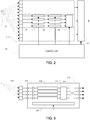
- the processing for each group of sensors, as well as the ADC for that block are integrated into a single electronic circuit or package (referred to below as a unit), as illustrated in FIG. 3 .
- a set of sensor inputs is provided as analog signals, illustrated as four separate inputs in the figure, understanding that other examples, may have different numbers of inputs (e.g., 8, 14 for a 4x4 patch, etc.).
- the unit optionally includes analog signal amplification elements 310, whose gain is optionally controllable by a controller 330 in the unit.
- the unit includes a number signal processing blocks 320, 323. In some examples, a separate signal processing block 320 is associated with each input, and another signal processing block 323 is used for combination of the signals.
- each signal processing block 320 performs a discrete (sampled) time analog signal domain processing of the signal, for example, using switched capacitor techniques as described above.
- the controller 330 is coupled to the processing blocks 320 to coordinate operation of the switches in the block in order to cause the desired sequence of charge sharing to implement desired signal processing functions, such as fractional sampling period delay, matched filtering, etc.
- the entire processing block 320 is passive in that gain is not introduced into the signal path through the block (recognizing that the switches in the block may be implemented using transistors, which are active devices, but the block nevertheless is passive with respect to the signal path).
- further signal amplification may be introduced in the signal path, for example, between the signal blocks 320 and the combination signal block 323.
- the combination block is controllable to perform a sum or average of the ouputs of the processing blocks 320, and an envelope detection (e.g., rectification and smoothing).
- envelope detection e.g., rectification and smoothing
- analog outputs are provided from the unit, while in units as illustrated in FIG. 3 , one or more analog-to-digital converters 340 process output of the processing block 323. Note that as illustrated the combination block 323 has the same number of inputs as outputs, but it should be understood that in some versions, the block performs a reduction in the number of signals.
- multiple of such units are integrated together in one circuit or package to process all the signals provided by the ultrasonic elements 115 of a probe array.
- the transmit portion of the probe e.g., the transmit signal former 140
- each of multiple transducer outputs being driven by a corresponding signal that is appropriately delayed a fractional amount in a discrete time analog processing stage in order to focus the transmitted signals on the point in the body being images.
- the description above may focus on use of the analog signal processing to implement delay-based beamforming, other embodiments may perform other types of signal processing in the analog domain.
- the signal processing blocks may perform joint processing, effectively implementing a multidimensional signal processing approach using the discrete time analog signal processing techniques referred to above.
- a transform approach may be used.
- an analog implementation of a Discrete Cosine Transform (DCT) can be used to encode segments of the sensor grid (e.g., prior to or after performing delay based processing).
- a DCT or other transform may be used to compress the signal to reduce the amount of information that needs to be transmitted from or stored at the probe.
- the probe is configurable to perform such operations at the command of the controller at the probe and/or at the command of the base unit.
- functions that may be implemented in such a matrix form include transforms (e.g., effectively using square matrices) and projections (e.g., using rectangular matrices).
- a compressive sensing approach may be used in which a high number of sensor values are projected into a lower dimensional signal that is processed or transmitted for further processing.
- the matrix operations are performed in stages, for example, combining subsets (e.g., patches) of sensors in a first matrix operation, and then combining the outputs across multiple subsets in successive stages.
- a configurable probe can provide conventional beamforming functions are well as more complex multidimensional operations on the sensed signals.
- the processing in the main section provides control and/or feedback signals to configure or control the analog processing in the probe.
- the feedback may provide updated projection matrices for compressive sensing applications, gain control, and beam forming pattern. This feedback may be based, for example, on predicted characteristics of the sensed signals, which may be based on estimates of motion of the probe or body being sensed.
- the analog processing may include probabilistic computation, for instance, using model based or Bayesian approaches.
- the processing e.g., at the base unit of the system
- the analog processing may all be performed in a probe, and optionally digitized before being transmitted using a wired or wireless link to a main section of the system.
- the analog and/or digital processing may be controlled by software stored in a computer-readable for controlling a processor, such as a digital signal processor or general purpose computer.
- software controlling the probe including controlling the operation of the analog domain filters and transformation stages, is uploaded to the probe from the base unit, and stored in a tangible storage medium at the probe.
Landscapes
- Engineering & Computer Science (AREA)
- Physics & Mathematics (AREA)
- Radar, Positioning & Navigation (AREA)
- Remote Sensing (AREA)
- Acoustics & Sound (AREA)
- Life Sciences & Earth Sciences (AREA)
- Computer Networks & Wireless Communication (AREA)
- General Physics & Mathematics (AREA)
- Health & Medical Sciences (AREA)
- Pathology (AREA)
- Surgery (AREA)
- Nuclear Medicine, Radiotherapy & Molecular Imaging (AREA)
- Veterinary Medicine (AREA)
- Radiology & Medical Imaging (AREA)
- Biomedical Technology (AREA)
- Heart & Thoracic Surgery (AREA)
- Medical Informatics (AREA)
- Molecular Biology (AREA)
- Biophysics (AREA)
- Animal Behavior & Ethology (AREA)
- General Health & Medical Sciences (AREA)
- Public Health (AREA)
- Multimedia (AREA)
- Computer Hardware Design (AREA)
- General Engineering & Computer Science (AREA)
- Ultra Sonic Daignosis Equipment (AREA)
Claims (12)
- Ultraschallverarbeitungssystem, das Folgendes umfasst:mehrere steuerbare Eingabeverarbeitungsblöcke (320), wovon jeder eine zeitdiskrete Analogsignalverarbeitungsstufe zum Verarbeiten eines oder mehrerer entsprechender Eingangssignale, die Ultraschallsignale darstellen, implementiert, wobei jeder Eingabeverarbeitungsblock Folgendes umfasst:eine erste Verzögerungsstufe (121), die gesteuert werden kann, um relative Verzögerungen zwischen Signalen einzuführen, wobei die relativen Verzögerungen ein Vielfaches der Abtastperiode der Signalverarbeitungsstufe sind; undeine zweite Verzögerungsstufe (122), die gesteuert werden kann, um relative Verzögerungen zwischen Signalen einzuführen, wobei die relativen Verzögerungen ein Bruchteil der Abtastperiode der Signalverarbeitungsstufe sind;wobei für jeden Eingabeverarbeitungsblock:die bruchteiligen Verzögerungen der zweiten Verzögerungsstufe unter Verwendung eines Filters mit endlicher Impulsantwort (FIR-Filter), das mehrere kapazitive Elemente und mehrere Schalter zum Steuern der Ladungsübertragung zwischen den kapazitiven Elementen umfasst, implementiert werden;ein Eingang der zweiten Verzögerungsstufe an einen Ausgang der ersten Verzögerungsstufe derart gekoppelt ist, dass die mehreren kapazitiven Elemente basierend auf der Ausgabe der ersten Verzögerungsstufe geladen werden; undEigenschaften der FIR-Filter entsprechend der Sequenzierung des Betriebs der Schalter gesteuert werden können.
- Ultraschallverarbeitungssystem nach Anspruch 1, das ferner eines oder mehrere der folgenden Elemente umfasst:a) mehrere Ultraschallelemente (115), die jeweils an einen entsprechenden Eingabeverarbeitungsblock gekoppelt sind, um ein Signal bereitzustellen, das ein Ultraschallsignal darstellt, das an dem Ultraschallelement empfangen worden ist;b) mehrere Verstärker (310), die jeweils an einen Eingang eines entsprechenden Eingabeverarbeitungsblocks (320) gekoppelt sind;c) einen Analog/Digital-Umsetzer (340), der an einen Ausgang jeder der Verarbeitungsstufen gekoppelt ist;d) mehrere steuerbare Ausgabeverarbeitungsblöcke zum Erzeugen eines entsprechenden Signals für die Emission als ein Ultraschallsignal, wobei jeder Block eine zeitdiskrete Analogsignalverarbeitungsstufe implementiert, und gesteuert werden kann, um eine relative Verzögerung zwischen Signalen einzuführen, die ein Bruchteil der Abtastperiode der Signalverarbeitungsstufe sind.
- Ultraschallverarbeitungssystem nach Anspruch 2, das ferner eine Steuereinrichtung (130, 330) umfasst, die an die Eingabeverarbeitungsblöcke gekoppelt sind, um den Betrieb des einen oder mehrerer der Eingabeverarbeitungsblöcke (320) zu steuern.
- Ultraschallverarbeitungssystem nach Anspruch 1, das ferner Folgendes umfasst: eine Kombinationsschaltungsanordnung (123, 323) zum Kombinieren mehrerer Ausgaben der Eingabeverarbeitungsblöcke, um ein kombiniertes Signal zu bilden.
- Ultraschallverarbeitungssystem nach Anspruch 4, wobei einer oder mehrere der folgenden Punkte zutreffen:a) das System umfasst ferner einen Analog/Digital-Umsetzer (ADC), der an einen Ausgang der Kombinationsschaltungsanordnung gekoppelt ist;b) die Sonde ist mit einer Basiseinheit durch eine Kommunikationsverbindung verbunden, die dafür geeignet ist, die kombinierten Signale an die Basiseinheit weiterzugeben.
- Ultraschallsystem nach Anspruch 4, wobei sich die Eingabeverarbeitungsblöcke (320) und die Kombinationsschaltungsanordnung (123, 323) in einer tragbaren Sonde des System befinden.
- Ultraschallsystem nach Anspruch 1, das ferner eine Steuereinrichtung (130, 330) umfasst, die an die Eingabeverarbeitungsblöcke gekoppelt ist, um die Eingabeverarbeitungsblöcke wiederholt neu zu konfigurieren.
- Ultraschallsystem nach Anspruch 7, das ferner Folgendes umfasst: eine Kombinationsschaltungsanordnung (123, 323) zum Kombinieren mehrerer Ausgaben der Eingabeverarbeitungsblöcke, um ein kombiniertes Signal zu bilden, wobei die Steuereinrichtung (130, 330) auf die kombinierten Signale reagiert, um sich an Signalerfassungseigenschaften der Eingabesignale anzupassen.
- Ultraschallsystem nach Anspruch 1, wobei jeder Eingabeverarbeitungsblock (320) Folgendes umfasst:mehrere passive Signalskalierungsschaltungen, die jeweils zum Annehmen eines analogen Eingangssignalwerts und eines digitalen Skalierungssteuerungswerts, der einen Skalierungsfaktor darstellt, und zum Speichern einer analogen Darstellung eines skalierten Signalwertes, der gleich einem Produkt des angenommenen Signalwerts und des Skalierungsfaktors ist, in einer Ausgabestufe für die Skalierungsschaltung, ausgelegt sind.
- Ultraschallsystem nach Anspruch 9, wobei jede Signalskalierungsschaltung mehrere schaltbare, miteinander verbundene kapazitive Elemente umfasst.
- Ultraschallsystem nach Anspruch 10, wobei im Betrieb der Skalierungsschaltung, der skalierte Signalwert in aufeinanderfolgenden Phasen gebildet wird, wobei jede Phase einer Konfiguration der schaltbaren Verbindung von kapazitiven Elementen zugeordnet ist, die Ladungsteilung unter miteinander verbundenen Kondensatoren erlaubt, und mindestens eines der kapazitiven Elemente entsprechend dem digitalen Skalierungssteuerungswert konfiguriert ist.
- Verfahren zum Verarbeiten von durch Ultraschall erzeugten Signalen, das Folgendes umfasst:Annehmen mehrerer von mehreren durch Ultraschall erzeugten Signale;Verarbeiten der Signale in mehreren steuerbaren Eingabeverarbeitungsblöcken (320), die das Durchführen einer zeitdiskreten Analogsignalverarbeitung der Signale enthält;Steuern der Eingabeverarbeitungsblöcke, das Folgendes enthält:Einführen von relativen Verzögerungen zwischen Signalen, die einem Vielfachen der Abtastperiode der Signalverarbeitungsstufe entsprechen, über eine erste Verzögerungsstufe (121); undEinführen von relativen Verzögerungen zwischen Signalen, die einem Bruchteil der Abtastperiode der Signalverarbeitungsstufe entsprechen, über eine zweite Verzögerungsstufe (122);wobei:die bruchteiligen Verzögerungen der zweiten Verzögerungsstufe durch jeden Eingabeverarbeitungsblock unter Verwendung eines Filters mit endlicher Impulsantwort (FIR-Filter), das mehrere kapazitive Elemente und mehrere Schalter zum Steuern der Ladungsübertragung zwischen den kapazitiven Elementen umfasst, implementiert werden;für jeden Eingabeverarbeitungsblock ein Eingang der zweiten Verzögerungsstufe an einen Ausgang der ersten Verzögerungsstufe derart gekoppelt ist, dass die mehreren kapazitiven Elemente basierend auf der Ausgabe der ersten Verzögerungsstufe geladen werden; unddas Durchführen der zeitdiskreten Analogsignalverabeitung der Signale das Steuern der Sequenzierung des Betriebs der Schalter enthält.
Applications Claiming Priority (3)
| Application Number | Priority Date | Filing Date | Title |
|---|---|---|---|
| US35781910P | 2010-06-23 | 2010-06-23 | |
| US37494610P | 2010-08-18 | 2010-08-18 | |
| PCT/US2011/041625 WO2011163475A1 (en) | 2010-06-23 | 2011-06-23 | Ultrasound imaging with analog processing |
Publications (3)
| Publication Number | Publication Date |
|---|---|
| EP2584971A1 EP2584971A1 (de) | 2013-05-01 |
| EP2584971A4 EP2584971A4 (de) | 2014-08-06 |
| EP2584971B1 true EP2584971B1 (de) | 2021-11-10 |
Family
ID=45371820
Family Applications (1)
| Application Number | Title | Priority Date | Filing Date |
|---|---|---|---|
| EP11798920.2A Active EP2584971B1 (de) | 2010-06-23 | 2011-06-23 | Ultraschallbildgebung mit analogverarbeitung |
Country Status (3)
| Country | Link |
|---|---|
| EP (1) | EP2584971B1 (de) |
| CN (1) | CN103096805B (de) |
| WO (1) | WO2011163475A1 (de) |
Families Citing this family (10)
| Publication number | Priority date | Publication date | Assignee | Title |
|---|---|---|---|---|
| US9244043B2 (en) * | 2012-08-23 | 2016-01-26 | General Electric Company | Integrated active ultrasonic probe |
| US11092680B2 (en) | 2014-12-19 | 2021-08-17 | University Of Rochester | Ultrasound system for high-speed and high resolution imaging applications |
| CN108474755B (zh) * | 2015-11-20 | 2021-11-26 | 集成动态电子解决方案公司 | 时间压缩感测系统 |
| US11249188B2 (en) * | 2015-12-30 | 2022-02-15 | Koninklijke Philips N.V. | System and method for dynamic filtering |
| US10624613B2 (en) | 2016-01-15 | 2020-04-21 | Butterfly Network, Inc. | Ultrasound signal processing circuitry and related apparatus and methods |
| CN105748103B (zh) * | 2016-04-22 | 2019-08-23 | 深圳先进技术研究院 | 一种延迟激励超声成像方法及装置 |
| US10231713B2 (en) | 2016-09-13 | 2019-03-19 | Butterfly Network, Inc. | Analog-to-digital drive circuitry having built-in time gain compensation functionality for ultrasound applications |
| CA3044227A1 (en) | 2016-11-22 | 2018-05-31 | University Of Rochester | Deep tissue super-resolution ultrasound imaging method and system |
| CN112041698A (zh) * | 2018-02-16 | 2020-12-04 | 皇家飞利浦有限公司 | 数字超声线缆和相关联的设备、系统和方法 |
| DE102022107066A1 (de) | 2022-03-25 | 2023-09-28 | Valeo Schalter Und Sensoren Gmbh | Ultraschallsensor mit zuschaltbarem Kerbfilter |
Citations (1)
| Publication number | Priority date | Publication date | Assignee | Title |
|---|---|---|---|---|
| US5469851A (en) * | 1994-08-09 | 1995-11-28 | Hewlett-Packard Company | Time multiplexed digital ultrasound beamformer |
Family Cites Families (9)
| Publication number | Priority date | Publication date | Assignee | Title |
|---|---|---|---|---|
| US4173007A (en) * | 1977-07-01 | 1979-10-30 | G. D. Searle & Co. | Dynamically variable electronic delay lines for real time ultrasonic imaging systems |
| US5573001A (en) * | 1995-09-08 | 1996-11-12 | Acuson Corporation | Ultrasonic receive beamformer with phased sub-arrays |
| US6193659B1 (en) | 1997-07-15 | 2001-02-27 | Acuson Corporation | Medical ultrasonic diagnostic imaging method and apparatus |
| DE60042335D1 (de) * | 1999-12-24 | 2009-07-16 | Koninkl Philips Electronics Nv | Mehrkanal-audiosignalverarbeitungsgerät |
| WO2002017298A1 (en) | 2000-08-24 | 2002-02-28 | Koninklijke Philips Electronics N.V. | Ultrasonic diagnostic imaging system with dynamic microbeamforming |
| US7164768B2 (en) * | 2001-06-21 | 2007-01-16 | Bose Corporation | Audio signal processing |
| US20050261596A1 (en) * | 2004-05-24 | 2005-11-24 | Smith Brian A | Passive switched capacitor high-pass filter for implantable cardiac device |
| CA2935422C (en) * | 2005-11-02 | 2019-01-08 | Visualsonics Inc. | High frequency array ultrasound system |
| US8188753B2 (en) | 2009-02-18 | 2012-05-29 | Analog Devices, Inc. | Analog computation |
-
2011
- 2011-06-23 WO PCT/US2011/041625 patent/WO2011163475A1/en active Application Filing
- 2011-06-23 EP EP11798920.2A patent/EP2584971B1/de active Active
- 2011-06-23 CN CN201180037700.2A patent/CN103096805B/zh active Active
Patent Citations (1)
| Publication number | Priority date | Publication date | Assignee | Title |
|---|---|---|---|---|
| US5469851A (en) * | 1994-08-09 | 1995-11-28 | Hewlett-Packard Company | Time multiplexed digital ultrasound beamformer |
Also Published As
| Publication number | Publication date |
|---|---|
| CN103096805A (zh) | 2013-05-08 |
| EP2584971A4 (de) | 2014-08-06 |
| CN103096805B (zh) | 2016-06-29 |
| WO2011163475A1 (en) | 2011-12-29 |
| EP2584971A1 (de) | 2013-05-01 |
Similar Documents
| Publication | Publication Date | Title |
|---|---|---|
| EP2584971B1 (de) | Ultraschallbildgebung mit analogverarbeitung | |
| JP5847719B2 (ja) | 超音波3次元画像形成システム | |
| EP1554605B1 (de) | Verfahren und vorrichtung für eine 1d-array-ultraschallsonde | |
| US5997479A (en) | Phased array acoustic systems with intra-group processors | |
| US8717843B2 (en) | Method and apparatus for ultrasound image acquisition | |
| US20080262351A1 (en) | Microbeamforming Transducer Architecture | |
| JP5649576B2 (ja) | 3次元超音波画像形成システム | |
| US11154276B2 (en) | Ultrasound beamforming system and method with reconfigurable aperture | |
| WO2007127147A2 (en) | Multi-dimensional cmut array with integrated beamformation | |
| KR102025258B1 (ko) | 서브 어레이를 갖는 트랜스듀서에서 평면파를 이용한 이미지 합성 방법 및 장치 | |
| JP5443326B2 (ja) | 携帯式超音波撮像システム及びプログラム | |
| Um et al. | 24.8 an analog-digital-hybrid single-chip RX beamformer with non-uniform sampling for 2D-CMUT ultrasound imaging to achieve wide dynamic range of delay and small chip area | |
| KR20150041471A (ko) | 빔포밍 장치 및 빔포밍 방법 | |
| US20180299537A1 (en) | Beamforming apparatus, beamforming method, and ultrasonic imaging apparatus | |
| JP2019526351A (ja) | マルチラインデジタルマイクロビーム形成器を含む超音波プローブ | |
| Roman et al. | An open-source test-bench for autonomous ultrasound imaging | |
| Kim et al. | Hybrid volume beamforming for 3-D ultrasound imaging using 2-D CMUT arrays | |
| Cacko et al. | Low-power ultrasound imaging on mixed FPGA/GPU systems | |
| JP2010082371A (ja) | 超音波受信ビーム成形装置 | |
| Stuart et al. | An architecture and implementation of real-time synthetic aperture compounding with SARUS | |
| Kim et al. | Hybrid beamformation for volumetric ultrasound imaging scanners using 2-D array transducers |
Legal Events
| Date | Code | Title | Description |
|---|---|---|---|
| PUAI | Public reference made under article 153(3) epc to a published international application that has entered the european phase |
Free format text: ORIGINAL CODE: 0009012 |
|
| 17P | Request for examination filed |
Effective date: 20121219 |
|
| AK | Designated contracting states |
Kind code of ref document: A1 Designated state(s): AL AT BE BG CH CY CZ DE DK EE ES FI FR GB GR HR HU IE IS IT LI LT LU LV MC MK MT NL NO PL PT RO RS SE SI SK SM TR |
|
| DAX | Request for extension of the european patent (deleted) | ||
| A4 | Supplementary search report drawn up and despatched |
Effective date: 20140709 |
|
| RIC1 | Information provided on ipc code assigned before grant |
Ipc: G01S 7/52 20060101AFI20140703BHEP |
|
| STAA | Information on the status of an ep patent application or granted ep patent |
Free format text: STATUS: EXAMINATION IS IN PROGRESS |
|
| 17Q | First examination report despatched |
Effective date: 20170209 |
|
| STAA | Information on the status of an ep patent application or granted ep patent |
Free format text: STATUS: EXAMINATION IS IN PROGRESS |
|
| GRAP | Despatch of communication of intention to grant a patent |
Free format text: ORIGINAL CODE: EPIDOSNIGR1 |
|
| STAA | Information on the status of an ep patent application or granted ep patent |
Free format text: STATUS: GRANT OF PATENT IS INTENDED |
|
| INTG | Intention to grant announced |
Effective date: 20210602 |
|
| RAP3 | Party data changed (applicant data changed or rights of an application transferred) |
Owner name: ANALOG DEVICES, INC. |
|
| GRAS | Grant fee paid |
Free format text: ORIGINAL CODE: EPIDOSNIGR3 |
|
| GRAA | (expected) grant |
Free format text: ORIGINAL CODE: 0009210 |
|
| STAA | Information on the status of an ep patent application or granted ep patent |
Free format text: STATUS: THE PATENT HAS BEEN GRANTED |
|
| AK | Designated contracting states |
Kind code of ref document: B1 Designated state(s): AL AT BE BG CH CY CZ DE DK EE ES FI FR GB GR HR HU IE IS IT LI LT LU LV MC MK MT NL NO PL PT RO RS SE SI SK SM TR |
|
| REG | Reference to a national code |
Ref country code: GB Ref legal event code: FG4D |
|
| REG | Reference to a national code |
Ref country code: AT Ref legal event code: REF Ref document number: 1446573 Country of ref document: AT Kind code of ref document: T Effective date: 20211115 Ref country code: CH Ref legal event code: EP |
|
| REG | Reference to a national code |
Ref country code: DE Ref legal event code: R096 Ref document number: 602011072086 Country of ref document: DE |
|
| REG | Reference to a national code |
Ref country code: IE Ref legal event code: FG4D |
|
| REG | Reference to a national code |
Ref country code: LT Ref legal event code: MG9D |
|
| REG | Reference to a national code |
Ref country code: NL Ref legal event code: MP Effective date: 20211110 |
|
| REG | Reference to a national code |
Ref country code: AT Ref legal event code: MK05 Ref document number: 1446573 Country of ref document: AT Kind code of ref document: T Effective date: 20211110 |
|
| PG25 | Lapsed in a contracting state [announced via postgrant information from national office to epo] |
Ref country code: RS Free format text: LAPSE BECAUSE OF FAILURE TO SUBMIT A TRANSLATION OF THE DESCRIPTION OR TO PAY THE FEE WITHIN THE PRESCRIBED TIME-LIMIT Effective date: 20211110 Ref country code: LT Free format text: LAPSE BECAUSE OF FAILURE TO SUBMIT A TRANSLATION OF THE DESCRIPTION OR TO PAY THE FEE WITHIN THE PRESCRIBED TIME-LIMIT Effective date: 20211110 Ref country code: FI Free format text: LAPSE BECAUSE OF FAILURE TO SUBMIT A TRANSLATION OF THE DESCRIPTION OR TO PAY THE FEE WITHIN THE PRESCRIBED TIME-LIMIT Effective date: 20211110 Ref country code: BG Free format text: LAPSE BECAUSE OF FAILURE TO SUBMIT A TRANSLATION OF THE DESCRIPTION OR TO PAY THE FEE WITHIN THE PRESCRIBED TIME-LIMIT Effective date: 20220210 Ref country code: AT Free format text: LAPSE BECAUSE OF FAILURE TO SUBMIT A TRANSLATION OF THE DESCRIPTION OR TO PAY THE FEE WITHIN THE PRESCRIBED TIME-LIMIT Effective date: 20211110 |
|
| PG25 | Lapsed in a contracting state [announced via postgrant information from national office to epo] |
Ref country code: IS Free format text: LAPSE BECAUSE OF FAILURE TO SUBMIT A TRANSLATION OF THE DESCRIPTION OR TO PAY THE FEE WITHIN THE PRESCRIBED TIME-LIMIT Effective date: 20220310 Ref country code: SE Free format text: LAPSE BECAUSE OF FAILURE TO SUBMIT A TRANSLATION OF THE DESCRIPTION OR TO PAY THE FEE WITHIN THE PRESCRIBED TIME-LIMIT Effective date: 20211110 Ref country code: PT Free format text: LAPSE BECAUSE OF FAILURE TO SUBMIT A TRANSLATION OF THE DESCRIPTION OR TO PAY THE FEE WITHIN THE PRESCRIBED TIME-LIMIT Effective date: 20220310 Ref country code: PL Free format text: LAPSE BECAUSE OF FAILURE TO SUBMIT A TRANSLATION OF THE DESCRIPTION OR TO PAY THE FEE WITHIN THE PRESCRIBED TIME-LIMIT Effective date: 20211110 Ref country code: NO Free format text: LAPSE BECAUSE OF FAILURE TO SUBMIT A TRANSLATION OF THE DESCRIPTION OR TO PAY THE FEE WITHIN THE PRESCRIBED TIME-LIMIT Effective date: 20220210 Ref country code: NL Free format text: LAPSE BECAUSE OF FAILURE TO SUBMIT A TRANSLATION OF THE DESCRIPTION OR TO PAY THE FEE WITHIN THE PRESCRIBED TIME-LIMIT Effective date: 20211110 Ref country code: LV Free format text: LAPSE BECAUSE OF FAILURE TO SUBMIT A TRANSLATION OF THE DESCRIPTION OR TO PAY THE FEE WITHIN THE PRESCRIBED TIME-LIMIT Effective date: 20211110 Ref country code: HR Free format text: LAPSE BECAUSE OF FAILURE TO SUBMIT A TRANSLATION OF THE DESCRIPTION OR TO PAY THE FEE WITHIN THE PRESCRIBED TIME-LIMIT Effective date: 20211110 Ref country code: GR Free format text: LAPSE BECAUSE OF FAILURE TO SUBMIT A TRANSLATION OF THE DESCRIPTION OR TO PAY THE FEE WITHIN THE PRESCRIBED TIME-LIMIT Effective date: 20220211 Ref country code: ES Free format text: LAPSE BECAUSE OF FAILURE TO SUBMIT A TRANSLATION OF THE DESCRIPTION OR TO PAY THE FEE WITHIN THE PRESCRIBED TIME-LIMIT Effective date: 20211110 |
|
| PG25 | Lapsed in a contracting state [announced via postgrant information from national office to epo] |
Ref country code: SM Free format text: LAPSE BECAUSE OF FAILURE TO SUBMIT A TRANSLATION OF THE DESCRIPTION OR TO PAY THE FEE WITHIN THE PRESCRIBED TIME-LIMIT Effective date: 20211110 Ref country code: SK Free format text: LAPSE BECAUSE OF FAILURE TO SUBMIT A TRANSLATION OF THE DESCRIPTION OR TO PAY THE FEE WITHIN THE PRESCRIBED TIME-LIMIT Effective date: 20211110 Ref country code: RO Free format text: LAPSE BECAUSE OF FAILURE TO SUBMIT A TRANSLATION OF THE DESCRIPTION OR TO PAY THE FEE WITHIN THE PRESCRIBED TIME-LIMIT Effective date: 20211110 Ref country code: EE Free format text: LAPSE BECAUSE OF FAILURE TO SUBMIT A TRANSLATION OF THE DESCRIPTION OR TO PAY THE FEE WITHIN THE PRESCRIBED TIME-LIMIT Effective date: 20211110 Ref country code: DK Free format text: LAPSE BECAUSE OF FAILURE TO SUBMIT A TRANSLATION OF THE DESCRIPTION OR TO PAY THE FEE WITHIN THE PRESCRIBED TIME-LIMIT Effective date: 20211110 Ref country code: CZ Free format text: LAPSE BECAUSE OF FAILURE TO SUBMIT A TRANSLATION OF THE DESCRIPTION OR TO PAY THE FEE WITHIN THE PRESCRIBED TIME-LIMIT Effective date: 20211110 |
|
| REG | Reference to a national code |
Ref country code: DE Ref legal event code: R097 Ref document number: 602011072086 Country of ref document: DE |
|
| PLBE | No opposition filed within time limit |
Free format text: ORIGINAL CODE: 0009261 |
|
| STAA | Information on the status of an ep patent application or granted ep patent |
Free format text: STATUS: NO OPPOSITION FILED WITHIN TIME LIMIT |
|
| 26N | No opposition filed |
Effective date: 20220811 |
|
| PG25 | Lapsed in a contracting state [announced via postgrant information from national office to epo] |
Ref country code: AL Free format text: LAPSE BECAUSE OF FAILURE TO SUBMIT A TRANSLATION OF THE DESCRIPTION OR TO PAY THE FEE WITHIN THE PRESCRIBED TIME-LIMIT Effective date: 20211110 |
|
| PG25 | Lapsed in a contracting state [announced via postgrant information from national office to epo] |
Ref country code: SI Free format text: LAPSE BECAUSE OF FAILURE TO SUBMIT A TRANSLATION OF THE DESCRIPTION OR TO PAY THE FEE WITHIN THE PRESCRIBED TIME-LIMIT Effective date: 20211110 |
|
| PG25 | Lapsed in a contracting state [announced via postgrant information from national office to epo] |
Ref country code: MC Free format text: LAPSE BECAUSE OF FAILURE TO SUBMIT A TRANSLATION OF THE DESCRIPTION OR TO PAY THE FEE WITHIN THE PRESCRIBED TIME-LIMIT Effective date: 20211110 |
|
| REG | Reference to a national code |
Ref country code: CH Ref legal event code: PL |
|
| REG | Reference to a national code |
Ref country code: BE Ref legal event code: MM Effective date: 20220630 |
|
| PG25 | Lapsed in a contracting state [announced via postgrant information from national office to epo] |
Ref country code: LU Free format text: LAPSE BECAUSE OF NON-PAYMENT OF DUE FEES Effective date: 20220623 Ref country code: LI Free format text: LAPSE BECAUSE OF NON-PAYMENT OF DUE FEES Effective date: 20220630 Ref country code: IE Free format text: LAPSE BECAUSE OF NON-PAYMENT OF DUE FEES Effective date: 20220623 Ref country code: CH Free format text: LAPSE BECAUSE OF NON-PAYMENT OF DUE FEES Effective date: 20220630 |
|
| PG25 | Lapsed in a contracting state [announced via postgrant information from national office to epo] |
Ref country code: IT Free format text: LAPSE BECAUSE OF FAILURE TO SUBMIT A TRANSLATION OF THE DESCRIPTION OR TO PAY THE FEE WITHIN THE PRESCRIBED TIME-LIMIT Effective date: 20211110 Ref country code: BE Free format text: LAPSE BECAUSE OF NON-PAYMENT OF DUE FEES Effective date: 20220630 |
|
| PGFP | Annual fee paid to national office [announced via postgrant information from national office to epo] |
Ref country code: FR Payment date: 20230523 Year of fee payment: 13 Ref country code: DE Payment date: 20230523 Year of fee payment: 13 |
|
| PGFP | Annual fee paid to national office [announced via postgrant information from national office to epo] |
Ref country code: GB Payment date: 20230523 Year of fee payment: 13 |
|
| PG25 | Lapsed in a contracting state [announced via postgrant information from national office to epo] |
Ref country code: HU Free format text: LAPSE BECAUSE OF FAILURE TO SUBMIT A TRANSLATION OF THE DESCRIPTION OR TO PAY THE FEE WITHIN THE PRESCRIBED TIME-LIMIT; INVALID AB INITIO Effective date: 20110623 |
|
| PG25 | Lapsed in a contracting state [announced via postgrant information from national office to epo] |
Ref country code: MK Free format text: LAPSE BECAUSE OF FAILURE TO SUBMIT A TRANSLATION OF THE DESCRIPTION OR TO PAY THE FEE WITHIN THE PRESCRIBED TIME-LIMIT Effective date: 20211110 Ref country code: CY Free format text: LAPSE BECAUSE OF FAILURE TO SUBMIT A TRANSLATION OF THE DESCRIPTION OR TO PAY THE FEE WITHIN THE PRESCRIBED TIME-LIMIT Effective date: 20211110 |