EP2584760B1 - Verfahren zur durchführung von videosuchen, ip-multimedia-subsystem-videoüberwachungssystem und überwachungs-front-end - Google Patents
Verfahren zur durchführung von videosuchen, ip-multimedia-subsystem-videoüberwachungssystem und überwachungs-front-end Download PDFInfo
- Publication number
- EP2584760B1 EP2584760B1 EP11797592.0A EP11797592A EP2584760B1 EP 2584760 B1 EP2584760 B1 EP 2584760B1 EP 11797592 A EP11797592 A EP 11797592A EP 2584760 B1 EP2584760 B1 EP 2584760B1
- Authority
- EP
- European Patent Office
- Prior art keywords
- monitoring
- peripheral unit
- server
- unit
- monitoring peripheral
- Prior art date
- Legal status (The legal status is an assumption and is not a legal conclusion. Google has not performed a legal analysis and makes no representation as to the accuracy of the status listed.)
- Not-in-force
Links
Images

Classifications
-
- H—ELECTRICITY
- H04—ELECTRIC COMMUNICATION TECHNIQUE
- H04L—TRANSMISSION OF DIGITAL INFORMATION, e.g. TELEGRAPHIC COMMUNICATION
- H04L65/00—Network arrangements, protocols or services for supporting real-time applications in data packet communication
- H04L65/10—Architectures or entities
- H04L65/1016—IP multimedia subsystem [IMS]
-
- H—ELECTRICITY
- H04—ELECTRIC COMMUNICATION TECHNIQUE
- H04L—TRANSMISSION OF DIGITAL INFORMATION, e.g. TELEGRAPHIC COMMUNICATION
- H04L65/00—Network arrangements, protocols or services for supporting real-time applications in data packet communication
- H04L65/1066—Session management
- H04L65/1069—Session establishment or de-establishment
-
- H—ELECTRICITY
- H04—ELECTRIC COMMUNICATION TECHNIQUE
- H04L—TRANSMISSION OF DIGITAL INFORMATION, e.g. TELEGRAPHIC COMMUNICATION
- H04L65/00—Network arrangements, protocols or services for supporting real-time applications in data packet communication
- H04L65/1066—Session management
- H04L65/1083—In-session procedures
- H04L65/1094—Inter-user-equipment sessions transfer or sharing
Definitions
- the disclosure relates to the field of multimedia communication technology, and in particular to a method for realizing video browsing based on IP Multimedia Subsystem (IMS) architecture, a video monitoring system and a monitoring peripheral unit.
- IMS IP Multimedia Subsystem
- the technical features and advantages, such as the IMS unified access control, the convergence of various multimedia services, and the multimedia service quality reliability are gradually approved by the telecom operators.
- the telecom operators are stepping up the deployment of the IMS core network, and gradually moving various services to the IMS core network.
- the unified access, unified call and media session establishing mode in the IMS can conveniently realize the service convergence among various applications.
- the network video monitoring service is essentially a multimedia service, and the realization of the network video monitoring service based on the IMS architecture is the development trend of the network video monitoring service technology.
- the video monitoring service has its own service model and service features, for example, there is home personal monitoring as well as public service oriented monitoring.
- a monitoring peripheral unit is often browsed by only one or a few monitoring clients; in this case, the way of directly establishing media session between the monitoring client and the monitoring peripheral unit can be adopted.
- the public service oriented monitoring for example, the monitoring in a scenic spot, there will be a large number of clients simultaneously accessing a monitoring peripheral unit to browse videos; in this case, because of the limitation of both hardware of the monitoring peripheral unit itself and network bandwidth, it is necessary to perform forwarding transmission of media stream through a media server, so as to utilize the delivery capability of the media server to simultaneously serve multiple monitoring clients.
- the traditional voice services e.g. voice call and video call
- voice call and video call are often realized on the IMS architecture by establishing point-to-point media session between two terminals, and some other services (e.g. audio conference and video conference) need to be realized via forwarding of the media server in the IMS network.
- CA 2394250 A1 (SUNGJIN C & CLTD [KR]) 31 January 2002 (2002-01-31) discloses a relaying system for multi-channel Internet broadcasting from a local live server, which makes it possible to have a multiple of live relaying servers shared by several local servers depending on the number of connections requested by client computers.
- CN101355580 A discloses that a network video monitoring system with a P2P mode and a transfer mode.
- US 2010/0125626 A1 discloses that a method of delivering content to a client includes receiving a request for the content from the client at a first server, determining the size of the content. The method further includes redirecting the client to the optimal server when the size of the content is above a threshold.
- the technical problem to be solved by the disclosure is to provide a method for realizing video browsing, an IMS video monitoring system and a monitoring peripheral unit, which can realize the optimized resource configuration under all kinds of service models for the video monitoring.
- an embodiment of the disclosure provides a method for realizing video browsing, applied to an IMS video monitoring system which includes a monitoring peripheral unit, an IMS core network and a server, according to independent claim 1.
- the process of converting the media session connections which have already been established between the monitoring peripheral unit and other monitoring client units such that the other monitoring client units browse the videos of the monitoring peripheral unit via the forwarding of the server may include:
- the method may further include:
- the disclosure further provides an IMS video monitoring system, which includes an IMS core network, a monitoring peripheral unit, and a server connected with the IMS core according to claim 4.
- the disclosure further provides a monitoring peripheral unit, according to independent claim 4, applied to an IMS video monitoring system which includes an IMS core network and a server.
- the disclosure provides a method for realizing video browsing which can realize the optimized resource configuration under all kinds of service models for the video monitoring and an IMS video monitoring system.
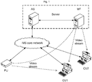
- the IMS video monitoring system includes:
- the monitoring client unit receives media stream (e.g. the video stream of the monitoring peripheral unit) through the network, decodes the video stream and displays video image.
- media stream e.g. the video stream of the monitoring peripheral unit
- the monitoring client unit as a kind of User Equipment (UE), is accessed to the IMS core network in a united manner, and the IMS core network performs security access authentication on the monitoring client unit uniformly.
- UE User Equipment
- the IMS core network implements routing and transmission of a signaling message, implements unified access and management of the UE, and can trigger different signaling to corresponding servers for process by setting a service triggering rule.
- the monitoring peripheral unit acquires and encodes analog video data, and sends the video stream through the network.
- the monitoring peripheral unit also as a kind of UE, is accessed to the IMS core network in a united manner, and the IMS core network performs security access authentication on the monitoring peripheral unit uniformly.
- the AS as a specific application server, takes charge of processing all services related to the video monitoring.
- the typical AS includes the following functional entities: Service Discovery Function (SDF), Service Selection Function (SSF), and Service Control Function (SCF).
- SDF Service Discovery Function
- SSF Service Selection Function
- SCF Service Control Function
- the implementation method for inside of the AS is not limited in this application.
- the MF implements media control, media delivery, media storage and other functions.
- the MF may either serve as a part of the AS, or directly use existing media control and delivery unit in the IMS core network.
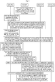
- an embodiment of the disclosure provides a method for realizing video browsing, applied to the IMS video monitoring system which includes the monitoring peripheral unit, the IMS core network and the server.
- the method includes the following steps.
- Step 21 the monitoring peripheral unit receives a first call request for browsing videos of the monitoring peripheral unit from a certain monitoring client unit, wherein the first call request is a call request directly routed to the monitoring peripheral unit by the IMS core network when no media session connection exists between the server and the monitoring peripheral unit.
- the IMS core network receives the first call request for browsing videos of the monitoring peripheral unit from the monitoring client unit.
- the IMS core network triggers the server connected with the IMS core network according to the first call request (specifically, sending the first call request to the server). If there is no media session connection established between the server and the monitoring peripheral unit, the server directly routes the first call request to the monitoring peripheral unit; or else, the server directly processes the first call request, and sends the video stream of the monitoring peripheral unit to the monitoring client unit.
- Step 22 it is determined whether the number of the media session connections directly established between the monitoring peripheral unit and other monitoring client units reaches the maximal connection number supported by the monitoring peripheral unit; if so, executing Step 23; or else, executing Step 24.
- Step 23 if the number of the media session connections directly established between the monitoring peripheral unit and other monitoring client units reaches the maximal connection number supported by the monitoring peripheral unit, the monitoring peripheral unit enables, according to the first call request, the monitoring client unit to browse the videos of the monitoring peripheral unit via the forwarding of the server.
- Step 24 if the number of the media session connections directly established between the monitoring peripheral unit and other monitoring client units does not reach the maximal connection number supported by the monitoring peripheral unit, a direct media session connection is established between the monitoring peripheral unit and the monitoring client unit so as to enable the monitoring client unit to browse the videos of the monitoring peripheral unit.
- the monitoring peripheral unit decides, according to the number of the media session connections already established, whether to establish a direct media session connection with the monitoring client unit or a media session connection via the forwarding of the server, so that the embodiment of the disclosure realizes the optimized resource configuration under all kinds of service models (e.g. the model of large concurrency of the monitoring client units or the model of small concurrency of the monitoring client units) for the video monitoring, and does not waste the server resource.
- the standard IMS call mode is adopted to establish a media session between the monitoring peripheral unit and the monitoring client unit and realize the switch between the direct connection and the way of forwarding-via-server, which does not influence the convergence between the video monitoring service and other various services in the whole IMS system.
- Step 23 the operation that, the monitoring peripheral unit enables, according to the first call request, the monitoring client unit to browse the videos of the monitoring peripheral unit via the forwarding of the server, specifically includes the following steps:
- the method may also include:
- Step 230 may specifically include:
- Step 230 may also specifically include:
- Step 230 the method may also include:
- the monitoring client unit is not limited to the dedicated video monitoring client unit; any standard client accessing to the IMS core network and supporting corresponding encoding format (e.g. a mobile phone with function of video call) can realize it.
- the monitoring client unit may not need to trigger the server and determine whether there is the media session connection between the server and the monitoring peripheral unit, it instead may directly route the call request to the monitoring peripheral unit in the normal way.
- the monitoring peripheral unit determines whether to forward the call request via a server according to the number of the currently established media session connections; if the monitoring peripheral unit determines that the number of the currently established media session connections reaches the maximal connection number supported by the monitoring peripheral unit, the current call request is processed by the server (i.e. the monitoring peripheral unit interacts with the application server, uploads its video steam to the media server, and guides the monitoring client unit to initiate the call request for browsing the videos to the server).
- Fig. 3 shows a specific implementation flowchart of the method shown in Fig. 2 , taking that two monitoring client units CU1 and CU2 request the monitoring Peripheral Unit (PU) for video browsing for example.
- PU Peripheral Unit
- Step 201 first, a service trigger rule is configured in the IMS core network, so that all the call requests to the monitoring peripheral unit are triggered to the AS for process, for example, by differentiating Public User Identities (PUI) of the monitoring peripheral unit.
- PUI Public User Identities
- Step 202 the monitoring peripheral unit presets the maximal number of media session connections that it can support (for example, 2 or 4 lines) according to its own hardware capability, bandwidth value and the like.
- the monitoring peripheral unit may reserve one line as the media session connection for uploading the video stream under the way of forwarding via a server.
- Step 203 the monitoring client unit CU1 initiates a call request to the monitoring peripheral unit.
- the AS determines whether the media session connection has been established between itself and the PU; if not, continues to route the call request to the PU for process.
- the PU determines whether the current connection number does not exceed the maximal connection number, if so, the PU accepts the call and establishes the direct media session connection between itself and the CU1.
- Step 204 after the direct media session connection between the PU and the CU1 is established successfully, the PU adds 1 to its connection number.
- Step 205 the monitoring client unit CU2 initiates the call request to the monitoring peripheral unit PU.
- the AS determines whether the media session connection has been established between itself and the PU; if not, continues to route the call request to the PU for process.
- Step 206 after receiving the call request of the CU2, the PU determines whether the current connection number exceeds the maximal connection number; if so, switches to the way of forwarding via a server.
- Step 207 the PU requests to upload the video stream and establishes the media session connection with the server (which may be an MF).
- the server which may be an MF.
- the PU calls the AS through SIP INVITE and establishes the media session connection; or the PU sends the SIP message to notify the AS, and then the AS initiatively calls the PU and establishes the media session connection.
- Step 208 the AS records that the media session connection has been successfully established with the PU.
- Step 209 for the call request initiated by the CU2, the PU cannot establish the direct connection media session; so the PU replies the redirection response defined by the standard in the call process, and guides the CU2 to initiate a call request again.
- Step 210 the CU2 initiates the call request to the PU again after receiving the redirection response.
- the AS determines that the media session connection between itself and the PU has been established, then the AS processes the call request, and establishes the media session connection between the CU2 and the AS (or MF).
- Step 211 for the situation that the PU does not reserve one line as the media session connection for uploading the video stream, the PU breaks one of the direct media session connections that have been established (i.e. breaks the direct media session connection that has been established between the PU and the CU1) and switches to use the way of forwarding via a server, at this point, the PU sends a notification message to notify the CU1 to initiatively update session information.
- Step 212 the CU1 receiving the notification initiatively updates the session parameters, and for example, uses re-INVITE to initiate a call.
- the AS processes the call and updates the session parameters therein (i.e. the IP address and port of the video stream sender), the CU1 establishes a forwarding media session with the AS (or MF), and obtains the video stream of the PU from the MF.
- the SIP/SDP protocol may be adopted as the interface protocol between the video monitoring AS and the IMS core network.
- the MF implements media control, media delivery, media storage and other functions, and may either use the existing media control and delivery unit in the IMS core network or the dedicated video monitoring service unit, which is not limited in this application.
- the MF may serve as a part of the AS; in the above flow of the disclosure, the AS and the MF are described as an entity (server).
- the interface between the MF and the AS can adopt either the standard SIP/SDP protocol, or a private protocol.
- Both the monitoring client unit and the monitoring peripheral unit serve as the UE in the IMS core network, and the interface protocol between them and the IMS core network adopts the SIP/SDP protocol. Both the monitoring client unit and the monitoring peripheral unit need to register in the IMS core network first of all.
- Media data of monitoring video stream may be transmitted between different UEs or between the UE and the MF.
- the SIP INVITE method is usually adopted to conduct call and establish the media session, and the media data of video stream is transmitted through the RTP/RTCP protocol.
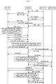
- Fig. 4 shows a flowchart of a specific application embodiment of the flow shown in Fig. 3 , and the method includes the following.
- Steps 301 to 307 describe the process of call and the media session connection establishment when the connection number of the monitoring peripheral unit does not exceed the maximal connection number.
- Step 301 the monitoring client unit CU1 requests to play real-time video of the monitoring peripheral unit.
- the CU1 initiates the SIP INVITE call to the PU; the message is sent through the IMS core network; and the IMS core network first triggers the call to a specific video monitoring AS according to a subscription data rule.
- Step 302 the video monitoring AS parses the SIP message, determines that no media session connection is established between the AS and the call target PU, and the AS does not perform further processing, but continues routing the call request to the PU.
- Step 303 the PU receives the call request from the CU1, determines that the current connection number does not exceed the maximal connection number, and then accepts the call request, and returns a 200 OK message.
- Step 304 the 200 OK message returned by the PU is returned back via the same route, and the CU1 receives the call accepting response from the PU.
- Step 305 - 306 the CU1 sends an acknowledgement message (ACK) to the PU.
- ACK acknowledgement message
- Step 307 the direct media session connection is established between the CU1 and the PU successfully.
- the PU starts to send the video stream to the CU1, wherein the transmission of the video stream usually adopts the RTP and RTCP protocol.
- the CU1 decodes and plays the received video stream, which means that requesting for browsing video is successful.
- the PU adds 1 to the current number of media session connections.
- Steps 308 to 319 describe the processing when the current connection number of the monitoring peripheral unit just reaches the maximal connection number.
- Step 308 another monitoring client unit CU2 in the system requests to play the videos of the PU.
- the CU2 initiates the SIP INVITE call to the PU; and the SIP message is first triggered to the AS when passing the IMS core network.
- Step 309 the AS determines that there is no media session connection between itself and the PU currently, and then the AS does not perform further processing, but continues routing the call request to the PU.
- Step 310 the PU receives the call request of the CU2, and checks the current number of media session connections; when the number reaches the preset maximal connection number, the subsequent media session needs to be established via the forwarding of a server.
- Step 311 the PU initiates the INVITE call to the AS to request to upload the video stream.
- Step 312 the AS accepts the call from the PU, and returns a 200 OK response.
- Step 313 after receiving the response from the AS, the PU sends an ACK to the AS.
- Step 314 after the call is established successfully, the media session connection is established between the PU and the AS.
- the PU sends the video stream to the AS, and the video stream is usually transmitted by using the RTP and RTCP protocol (in the embodiment, the MF is a part of the AS).
- Step 315 the AS records that the media session connection has been established between itself and the PU successfully, so that the AS can accepts a call when receiving the call to the PU from a certain CU again, and the forwarding media session is established between the AS and the CU.
- Steps 316 - 317 after the PU and the AS establish the media session connection of uploading the video stream successfully, for the call request from the CU2, the PU returns a 302 moved temporarily (redirection) response, wherein the address of redirection is still the address of the PU for guiding the CU2 to initiate a call request again.
- Steps 318 - 319 the CU2 sends an ACK message to the PU to confirm that the redirection response is received.
- Steps 320 to 324 describe the flow that the CU2 initiates the call to the PU again after receiving the redirection response.
- Step 320 the CU2 initiates an INVITE call to the PU again, and first triggers the call to the AS through the IMS core network.
- Step 321 the AS parses that the call target is the PU, and determines that the media session has been established between the AS and the target PU, at this point, the AS processes the call.
- Step 322 the AS sends the response (200 OK) representing acceptance of the call to the CU2;.
- Step 323 after receiving the call accepting response, the CU2 sends the ACK.
- Step 324 after receiving the ACK from the CU2, the AS starts to forward the video stream of the peripheral unit to the CU2, wherein the transmission of the video stream usually adopts the RTP and RTCP protocol; at this point, the forwarding media session is established between the CU2 and the AS successfully.
- Steps 325 to 331 describe the process of switching the direct connection media session between the PU and the CU1 to the forwarding media session.
- Step 325 the monitoring peripheral unit PU decides to switch the direct connection media session between itself and a certain client unit to the forwarding media session.
- the PU sends the SIP message to notify the CU1 to initiatively update session information; in the embodiment, the SIP INFO message may be adopted, but other SIP message, such as MESSAGE may also be adopted.
- the message may be sent via the existing SIP conversation between the PU and CU1, or may be sent outside the SIP conversation.
- Step 326 the CU1 returns the response (200 OK) after receiving the message.
- Step 327 the CU1 initiates a re-INVITE call, and the CU does not break the existing SIP call conversation, but only requests to update the session information.
- the CU1 initiates a re-INVITE call, and the CU does not break the existing SIP call conversation, but only requests to update the session information.
- only IP address and port of the media (video stream) sender are updated, and the message is first triggered to the AS through the IMS core network.
- Step 328 after receiving the call request, the AS determines that the media session has been established between itself and the PU.
- Steps 329 - 331 the AS processes the call request and returns an 200 OK message to the CU1, and the CU1 sends an ACK; so far the forwarding media session is established between the AS and the CU1 successfully, and the video stream of the PU is transmitted to the CU1.
- the method of the disclosure realizes the optimized resource configuration under all kinds of service models for the video monitoring, does not waste the server resources compared with the traditional video monitoring system which is not based on the IMS architecture. Besides, the method is implemented by adopting the standard call flow in the IMS system, which does not influence the convergence between the video monitoring service and other various services in the whole IMS system.
- the embodiment of the disclosure further provides an IMS video monitoring system, which includes the IMS core network, the monitoring peripheral unit and the server connected with the IMS core network; wherein the IMS core network is configured to receive a first call request for browsing videos of the monitoring peripheral unit from a certain monitoring client unit, and request to trigger the server according to the first call request; the server is configured, when no media session connection is established between itself and the monitoring peripheral unit, to notify the IMS core network to directly route the first call request to the monitoring peripheral unit; and the monitoring peripheral unit is configured to determine whether the number of the media session connections directly established between itself and other monitoring client units reaches the maximal connection number supported by itself according to the first call request, if so, enable the monitoring client unit to browse the videos of the monitoring peripheral unit via the forwarding of the server, otherwise, establish a direct media session connection between itself and the monitoring client unit so as to enable the monitoring client unit to browse the videos of the monitoring peripheral unit.
- the IMS core network is configured to receive a first call request for browsing videos of the monitoring peripheral unit from a certain monitoring client
- the embodiment of the disclosure further provides a monitoring peripheral unit, applied to the IMS video monitoring system which includes the IMS core network and the server; the monitoring peripheral unit includes:
- the processing module may include:
- the forwarding-via-server module may include:
- the monitoring peripheral unit may further include: a control module, which is configured, after the monitoring peripheral unit enables the monitoring client unit to browse the videos of the monitoring peripheral unit via the forwarding of the server according to the first call request, to convert the media session connections which have already been directly established between the monitoring peripheral unit and other monitoring client units such that the other monitoring client units browse the videos of the monitoring peripheral unit via the forwarding of the server.
- a control module which is configured, after the monitoring peripheral unit enables the monitoring client unit to browse the videos of the monitoring peripheral unit via the forwarding of the server according to the first call request, to convert the media session connections which have already been directly established between the monitoring peripheral unit and other monitoring client units such that the other monitoring client units browse the videos of the monitoring peripheral unit via the forwarding of the server.
- all the embodiments of the method are suitable for the embodiment of device; similarly, by establishing the media session connection between the monitoring peripheral unit and the monitoring client unit and implementing switching between direction connection and forwarding, and by the way that the monitoring peripheral unit decides whether to establish the direct connection media session or the forwarding media session according to its own connection number and implements the switching process without interrupting a call via updating the session parameters, the embodiment of device realizes the optimized resource configuration under all kinds of service models for the video monitoring, and does not waste the server resources compared with the traditional video monitoring system which is not based on the IMS architecture. Besides, the device is implemented by adopting the standard call flow in the IMS system, which does not influence the convergence between the video monitoring service and other various services in the whole IMS system.
Landscapes
- Engineering & Computer Science (AREA)
- Multimedia (AREA)
- Computer Networks & Wireless Communication (AREA)
- Signal Processing (AREA)
- Business, Economics & Management (AREA)
- General Business, Economics & Management (AREA)
- Telephonic Communication Services (AREA)
- Data Exchanges In Wide-Area Networks (AREA)
Claims (6)
- Ein Verfahren zur Durchführung von Videosuchen, angewandt auf ein IP-Multimedia-Subsystem-(IMS-)Videoüberwachungssystem, das eine periphere Überwachungseinheit, ein IMS-Kernnetzwerk und einen Server einschließt, wobei das Verfahren Folgendes umfasst:das Empfangen (21), durch die periphere Überwachungseinheit, einer ersten Verbindungsanforderung zum Durchsuchen von Videos der peripheren Überwachungseinheit von einer Client-Überwachungseinheit, wobei die erste Verbindungsanforderung eine Verbindungsanforderung ist, die von dem IMS-Kernnetzwerk direkt an die periphere Überwachungseinheit geleitet wird, wenn keine Mediensitzungsverbindung zwischen dem Server und der peripheren Überwachungseinheit vorhanden ist;Befähigen (22, 23), durch die periphere Überwachungseinheit entsprechend der ersten Verbindungsanforderung, der Client-Überwachungseinheit, die Videos der peripheren Überwachungseinheit zu durchsuchen, durch eine Weiterleitung durch den Server, wenn die Anzahl an Direktmediensitzungsverbindungen zwischen der peripheren Überwachungseinheit und anderen Client-Überwachungseinheiten eine maximale Verbindungsanzahl erreicht, die von der peripheren Überwachungseinheit unterstützt wird; ansonsten Herstellen (24) einer Direktmediensitzungsverbindung zwischen der peripheren Überwachungseinheit und der Client-Überwachungseinheit, um es der Client-Überwachungseinheit zu ermöglichen, die Videos der peripheren Überwachungseinheit zu durchsuchen, wobei das Verfahren weiter Folgendes umfasst: nach dem Prozess, den die periphere Überwachungseinheit ermöglicht, entsprechend der ersten Verbindungsanforderung, der Client-Überwachungseinheit, die Videos der peripheren Überwachungseinheit zu durchsuchen, durch das Weiterleiten durch den Server, wobei Mediensitzungsverbindungen umgewandelt werden, die bereits zwischen der peripheren Überwachungseinheit und anderen Client-Überwachungseinheiten hergestellt wurden, so dass die anderen Client-Überwachungseinheiten die Videos der peripheren Überwachungseinheit durchsuchen, durch die Weiterleitung durch den Server;wobei der Prozess, den die periphere Überwachungseinheit ermöglicht, entsprechend der ersten Verbindungsanforderung, der Client-Überwachungseinheit, die Videos der peripheren Überwachungseinheit zu durchsuchen, durch das Weiterleiten durch den Server, Folgendes umfasst:Interagieren, durch die periphere Überwachungseinheit, mit dem Server entsprechend der ersten Verbindungsanforderung, Führen der Client-Überwachungseinheit, um eine zweite Verbindungsanforderung zum Durchsuchen der Videos der peripheren Überwachungseinheit zu starten, um den Server zu veranlassen, einen Videostream der peripheren Überwachungseinheit an die Client-Überwachungseinheit entsprechend der zweiten Verbindungsanforderung zu senden;wobei der Prozess, dass die periphere Überwachungseinheit mit dem Server entsprechend der ersten Verbindungsanforderung interagiert und die Client-Überwachungseinheit führt, um eine zweite Verbindungsanforderung zum Durchsuchen der Videos der peripheren Überwachungseinheit zu starten, Folgendes umfasst:Heraufladen des Videostreams der peripheren Überwachungseinheit auf den Server durch die periphere Überwachungseinheit;Zurückliefern einer Umleitungsantwort an die Client-Überwachungseinheit durch die periphere Überwachungseinheit entsprechend der ersten Verbindungsanforderung, um die Client-Überwachungseinheit zu veranlassen, die zweite Verbindungsanforderung zum Durchsuchen der Videos der peripheren Überwachungseinheit entsprechend der Umleitungsantwort zu starten.
- Das Verfahren gemäß Anspruch 1, wobei der Prozess der Umwandlung der Mediensitzungsverbindungen, die bereits zwischen der peripheren Überwachungseinheit und anderen Client-Überwachungseinheiten hergestellt wurden, so dass die anderen Client-Überwachungseinheiten die Videos der peripheren Überwachungseinheit durchsuchen, durch das Weiterleiten durch den Server, Folgendes umfasst:wenn die periphere Überwachungseinheit eine Mediensitzungsverbindung freihält, die dafür reserviert ist, den Videostream auf den Server hochzuladen, das Senden einer Sitzungsaktualisierungsmeldung an die anderen Client-Überwachungseinheiten durch die periphere Überwachungseinheit, um die anderen Client-Überwachungseinheiten zu veranlassen, Sitzungsparameter entsprechend der Sitzungsaktualisierungsmeldung zu aktualisieren, und das Senden des Videostreams der peripheren Überwachungseinheit an die anderen Client-Überwachungseinheiten entsprechend den aktualisierten Sitzungsparametern durch den Server; oder,wenn die periphere Überwachungseinheit keine Mediensitzungsverbindung freihält, die dafür reserviert ist, den Videostream auf den Server hochzuladen, Unterbrechen, durch die periphere Überwachungseinheit, einer Mediensitzungsverbindung mit einer der anderen Client-Überwachungseinheiten und Wechseln, um die Weiterleitung durch den Server zu nutzen, Heraufladen des Videostreams auf den Server und Senden einer Sitzungsaktualisierungsmeldung an die Client-Überwachungseinheit, der die unterbrochene Mediensitzungsverbindung entspricht, um die entsprechende Client-Überwachungseinheit zu veranlassen, die Sitzungsparameter entsprechend der Sitzungsaktualisierungsmeldung zu aktualisieren, und Senden des Videostreams der peripheren Überwachungseinheit an die Client-Überwachungseinheit durch den Server entsprechend den aktualisierten Sitzungsparametern.
- Das Verfahren gemäß Anspruch 1 oder 2, das weiter Folgendes umfasst: nach dem Verfahren der Umwandlung von Mediensitzungsverbindungen, die bereits zwischen der peripheren Überwachungseinheit und anderen Client-Überwachungseinheiten hergestellt wurden, so dass die anderen Client-Überwachungseinheiten die Videos der peripheren Überwachungseinheit durch das Weiterleiten durch den Server durchsuchen, nachdem alle Client-Überwachungseinheiten mit Mediensitzungsverbindung mit dem Server aufgehört haben, den Videostream der peripheren Überwachungseinheit vom Server zu erhalten, Unterbrechen der Mediensitzungsverbindung mit der peripheren Überwachungseinheit durch den Server aus eigener Initiative.
- Eine periphere Überwachungseinheit, angewandt auf ein IMS-Videoüberwachungssystem, das ein IMS-Kernnetzwerk und einen Server umfasst, wobei die periphere Überwachungseinheit Folgendes umfasst:ein Empfangsmodul, konfiguriert, um eine erste Verbindungsanforderung zum Durchsuchen von Videos der peripheren Überwachungseinheit von einer Client-Überwachungseinheit zu empfangen, wobei die erste Verbindungsanforderung eine Verbindungsanforderung ist, die vom IMS-Kernnetzwerk direkt an die periphere Überwachungseinheit geleitet wird, wenn keine Mediensitzungsverbindung zwischen dem Server und der peripheren Überwachungseinheit existiert; undein Verarbeitungsmodul, konfiguriert, um, wenn die Anzahl der Mediensitzungsverbindungen, die direkt zwischen der peripheren Überwachungseinheit und anderen Client-Überwachungseinheiten hergestellt werden, die maximale Verbindungsanzahl erreicht, die von der peripheren Überwachungseinheit unterstützt wird, die Client-Überwachungseinheit zu befähigen, die Videos der peripheren Überwachungseinheit zu durchsuchen, durch eine Weiterleitung durch den Server entsprechend der ersten Verbindungsanforderung, ansonsten eine Direktmediensitzungsverbindung zwischen der peripheren Überwachungseinheit und der Client-Überwachungseinheit herzustellen, um es der Client-Überwachungseinheit zu ermöglichen, die Videos der peripheren Überwachungseinheit zu durchsuchen,wobei die periphere Überwachungseinheit Folgendes umfasst:ein Steuerungsmodul, konfiguriert, um, nachdem die periphere Überwachungseinheit es der Client-Überwachungseinheit ermöglicht hat, die Videos der peripheren Überwachungseinheit zu durchsuchen, durch die Weiterleitung durch den Server entsprechend der ersten Verbindungsanforderung, Mediensitzungsverbindungen, die direkt zwischen der peripheren Überwachungseinheit und anderen Client-Überwachungseinheiten erstellt wurden, umzuwandeln, so dass die anderen Client-Überwachungseinheiten die Videos der peripheren Überwachungseinheit durchsuchen, durch die Weiterleitung durch den Server;wobei das Verarbeitungsmodul Folgendes umfasst:ein Bestimmungsmodul, konfiguriert, um zu bestimmen, dass die Anzahl der Mediensitzungsverbindungen, die direkt zwischen der peripheren Überwachungseinheit und anderen Client-Überwachungseinheiten hergestellt werden, die maximale Verbindungsanzahl erreicht, die von der peripheren Überwachungseinheit unterstützt wird, und dann ein Weiterleitungs-über-den-Server-Modul auszulösen; unddas Weiterleitungs-über-den-Server-Modul, konfiguriert, um mit dem Server zu interagieren und die Client-Überwachungseinheit zu führen, um eine zweite Verbindungsanforderung zur Durchsuchung der Videos der peripheren Überwachungseinheit zu starten, um den Server zu veranlassen, einen Videostream der peripheren Überwachungseinheit an die Client-Überwachungseinheit entsprechend der zweiten Verbindungsanforderung zu senden;wobei das Weiterleitungs-über-den-Server-Modul Folgendes umfasst:ein Hochlademodul, konfiguriert, um den Videostream der peripheren Überwachungseinheit auf den Server heraufzuladen; undein Antwortmodul, konfiguriert, um eine Umleitungsantwort an die Client-Überwachungseinheit entsprechend der ersten Verbindungsanforderung zu senden, um die Client-überwachungseinheit zu veranlassen, die zweite Verbindungsanforderung zur Durchsuchung der Videos der peripheren Überwachungseinheit entsprechend der Umleitungsantwort zu starten und den Server zu veranlassen, den Videostream der peripheren Überwachungseinheit an die Client-Überwachungseinheit entsprechend der zweiten Verbindungsanforderung zu senden.
- Die periphere Überwachungseinheit gemäß Anspruch 4, wobei das Bestimmungsmodul konfiguriert ist, um zu bestimmen, wenn die Anzahl der Mediensitzungsverbindungen, die direkt zwischen der peripheren Überwachungseinheit und anderen Client-Überwachungseinheiten hergestellt werden, nicht die maximale Verbindungsanzahl erreicht, die von der peripheren Überwachungseinheit unterstützt wird, ein Direktsitzungsmodul auszulösen; und wobei das Direktsitzungsmodul konfiguriert ist, um die Direktmediensitzungsverbindung mit der Client-Überwachungseinheit herzustellen, um es so der Client-Überwachungseinheit zu ermöglichen, die Videos der peripheren Überwachungseinheit zu durchsuchen.
- Ein IMS-Videoüberwachungssystem, das ein IMS-Kernnetzwerk, die periphere Überwachungseinheit gemäß einem beliebigen der Ansprüche 4 oder 5 und einen Server umfasst, der mit dem IMS-Kernnetzwerk verbunden ist, wobei das IMS-Kernnetzwerk konfiguriert ist, um eine erste Verbindungsanforderung zum Durchsuchen von Videos der peripheren Überwachungseinheit von einer Client-Überwachungseinheit zu empfangen und um das Auslösen des Servers entsprechend der ersten Verbindungsanforderung anzufordern; und wobei der Server konfiguriert ist, um, wenn keine Mediensitzungsverbindung zwischen ihm und der peripheren Überwachungseinheit hergestellt ist, das IMS-Kernnetzwerk zu benachrichtigen, die erste Verbindungsanforderung direkt an die periphere Überwachungseinheit zu leiten.
Applications Claiming Priority (2)
| Application Number | Priority Date | Filing Date | Title |
|---|---|---|---|
| CN201010211873.9A CN101895569B (zh) | 2010-06-21 | 2010-06-21 | 视频浏览的实现方法、ims视频监控系统及监控前端 |
| PCT/CN2011/075812 WO2011160561A1 (zh) | 2010-06-21 | 2011-06-16 | 视频浏览的实现方法、ims视频监控系统及监控前端 |
Publications (3)
| Publication Number | Publication Date |
|---|---|
| EP2584760A1 EP2584760A1 (de) | 2013-04-24 |
| EP2584760A4 EP2584760A4 (de) | 2014-04-30 |
| EP2584760B1 true EP2584760B1 (de) | 2018-01-24 |
Family
ID=43104634
Family Applications (1)
| Application Number | Title | Priority Date | Filing Date |
|---|---|---|---|
| EP11797592.0A Not-in-force EP2584760B1 (de) | 2010-06-21 | 2011-06-16 | Verfahren zur durchführung von videosuchen, ip-multimedia-subsystem-videoüberwachungssystem und überwachungs-front-end |
Country Status (4)
| Country | Link |
|---|---|
| EP (1) | EP2584760B1 (de) |
| CN (1) | CN101895569B (de) |
| ES (1) | ES2665468T3 (de) |
| WO (1) | WO2011160561A1 (de) |
Families Citing this family (12)
| Publication number | Priority date | Publication date | Assignee | Title |
|---|---|---|---|---|
| CN101895569B (zh) * | 2010-06-21 | 2015-01-28 | 中兴通讯股份有限公司 | 视频浏览的实现方法、ims视频监控系统及监控前端 |
| CN102035840A (zh) * | 2010-12-15 | 2011-04-27 | 中兴通讯股份有限公司 | 双向语音对讲的实现方法及系统 |
| CN103384247B (zh) * | 2013-07-05 | 2016-03-30 | 福建星网锐捷通讯股份有限公司 | 一种基于sip监控系统的视频多播实现方法 |
| CN103702087B (zh) * | 2013-12-31 | 2017-02-01 | 浙江宇视科技有限公司 | 摄像机可支持的最大媒体流直连数获取方法及装置 |
| CN103763332B (zh) * | 2014-02-19 | 2017-07-28 | 广东天波信息技术股份有限公司 | 一种媒体流转发方式动态切换的方法和系统 |
| CN105025049B (zh) * | 2014-04-22 | 2019-03-22 | 深圳市尼得科技有限公司 | 一种媒体流存储方法、装置及服务器 |
| CN106358008B (zh) * | 2015-07-17 | 2020-09-29 | 三亚中兴软件有限责任公司 | 一种避免重复呼叫接入的方法及会议电视终端设备 |
| CN106604216A (zh) * | 2016-12-31 | 2017-04-26 | 广州博冠光电技术有限公司 | 一种双向语音与操作控制数据的传输控制方法及系统 |
| CN106791695A (zh) * | 2017-01-13 | 2017-05-31 | 邦彦技术股份有限公司 | 一种监控视频的分发方法及其装置 |
| CN109391606A (zh) * | 2017-08-14 | 2019-02-26 | 中兴通讯股份有限公司 | 一种通信方法、装置和移动终端 |
| CN117857518A (zh) * | 2022-12-30 | 2024-04-09 | 康丽红 | 基于通信传输的信息管理方法 |
| CN116886849A (zh) * | 2023-09-06 | 2023-10-13 | 中移(杭州)信息技术有限公司 | 双向音视频通话方法、装置、电子设备及存储介质 |
Family Cites Families (10)
| Publication number | Priority date | Publication date | Assignee | Title |
|---|---|---|---|---|
| CA2394250A1 (en) * | 2000-07-24 | 2002-01-31 | Sungjin C&C, Ltd. | Relaying system for broadcasting multi-channel internet television and networking method thereof |
| CN1913533B (zh) * | 2006-09-05 | 2011-01-12 | 北京天地互连信息技术有限公司 | 基于会话初始化协议的远程视频监控系统及其实现方法 |
| CN100566407C (zh) * | 2007-06-26 | 2009-12-02 | 南京联创网络科技有限公司 | 多种视频交换路由方式的瘦资源视频绑定策略方法 |
| CN101217648A (zh) * | 2008-01-08 | 2008-07-09 | 华为技术有限公司 | 视频监控信息的传递方法、装置及系统 |
| JP2011519498A (ja) * | 2008-03-18 | 2011-07-07 | アルカテル−ルーセント | Iptvシステムのユーザが監視システムからメディアストリームを取得できるようにするためのネットワーク要素、および対応する方法 |
| CN101355580A (zh) * | 2008-09-18 | 2009-01-28 | 北京中星微电子有限公司 | 具有p2p模式及转发模式的网络视频监控系统 |
| CN101409828A (zh) * | 2008-10-30 | 2009-04-15 | 中兴通讯股份有限公司 | 视频监控数据传输方法和系统、及视频监控中心服务器 |
| US8135840B2 (en) * | 2008-11-20 | 2012-03-13 | At&T Intellectual Property I, Lp | Systems and methods for directing content requests to servers |
| CN101448072A (zh) * | 2008-12-29 | 2009-06-03 | 北京中星微电子有限公司 | 网络视频监控系统的视频查看方法及系统 |
| CN101895569B (zh) * | 2010-06-21 | 2015-01-28 | 中兴通讯股份有限公司 | 视频浏览的实现方法、ims视频监控系统及监控前端 |
-
2010
- 2010-06-21 CN CN201010211873.9A patent/CN101895569B/zh not_active Expired - Fee Related
-
2011
- 2011-06-16 EP EP11797592.0A patent/EP2584760B1/de not_active Not-in-force
- 2011-06-16 ES ES11797592.0T patent/ES2665468T3/es active Active
- 2011-06-16 WO PCT/CN2011/075812 patent/WO2011160561A1/zh active Application Filing
Non-Patent Citations (1)
| Title |
|---|
| None * |
Also Published As
| Publication number | Publication date |
|---|---|
| EP2584760A1 (de) | 2013-04-24 |
| EP2584760A4 (de) | 2014-04-30 |
| WO2011160561A1 (zh) | 2011-12-29 |
| ES2665468T3 (es) | 2018-04-25 |
| CN101895569A (zh) | 2010-11-24 |
| CN101895569B (zh) | 2015-01-28 |
Similar Documents
| Publication | Publication Date | Title |
|---|---|---|
| EP2584760B1 (de) | Verfahren zur durchführung von videosuchen, ip-multimedia-subsystem-videoüberwachungssystem und überwachungs-front-end | |
| EP2236003B1 (de) | Ein verfahren und system zur sitzungskontrolle | |
| KR101049721B1 (ko) | 세션 설정 프로토콜 기반의 얼리 미디어 서비스 제공 방법 및 응용 서버 | |
| EP2640099B1 (de) | Verfahren, system und vorrichtung zur bereitstellung eines streaming-mediendienstes | |
| EP2672678B1 (de) | Verfahren, vorrichtung und endgerät zur gemeinsamen nutzung von iptv-inhalten | |
| KR101316020B1 (ko) | 통신 네트워크의 원격 사용자와의 멀티미디어 세션의 수립방법 | |
| KR101630653B1 (ko) | 홈 네트워크상에서 호 송수신을 위한 시스템 및 방법 | |
| US9363472B2 (en) | Video injection for video communication | |
| US20160028777A1 (en) | System And Method For Providing Multimedia Services | |
| US9686709B2 (en) | Method, apparatus and system for guaranteeing QoS of communication service in NAT scenario | |
| US20150022619A1 (en) | System and method for sharing multimedia content using a television receiver during a voice call | |
| US20180255182A1 (en) | Web Real-Time Client Communication Over a Stimulus Based Network | |
| EP2223520A1 (de) | Verfahren und vorrichtung zum umgang mit multimediarufen | |
| US8908853B2 (en) | Method and device for displaying information | |
| US20130051390A1 (en) | Method and apparatus for transmitting media resources | |
| WO2015058648A1 (zh) | 基于ip电话的留言业务处理方法及装置 | |
| KR102396634B1 (ko) | 무선 통신 시스템에서 메시지 수신 정보를 송신하기 위한 장치 및 방법 | |
| CN117062249A (zh) | 辅助提供实时通话能力的方法以及装置 | |
| EP2817961A1 (de) | System und verfahren zur gemeinsamen nutzung von multimedia-inhalten mit einem fernsehempfänger während eines sprachanrufs | |
| KR20090064523A (ko) | 얼리 세션을 이용한 세션 설정 프로토콜 기반의 얼리 미디어 서비스 제공 방법 및 응용 서버 | |
| WO2013048230A1 (en) | A system and method for session transfer from a public switched telephone network (pstn) device to a session initiation protocol (sip) device | |
| KR20090066265A (ko) | 세션 설정 프로토콜 기반의 얼리 미디어 서비스 제공 방법 및 응용 서버 |
Legal Events
| Date | Code | Title | Description |
|---|---|---|---|
| PUAI | Public reference made under article 153(3) epc to a published international application that has entered the european phase |
Free format text: ORIGINAL CODE: 0009012 |
|
| 17P | Request for examination filed |
Effective date: 20130118 |
|
| AK | Designated contracting states |
Kind code of ref document: A1 Designated state(s): AL AT BE BG CH CY CZ DE DK EE ES FI FR GB GR HR HU IE IS IT LI LT LU LV MC MK MT NL NO PL PT RO RS SE SI SK SM TR |
|
| DAX | Request for extension of the european patent (deleted) | ||
| REG | Reference to a national code |
Ref country code: DE Ref legal event code: R079 Ref document number: 602011045350 Country of ref document: DE Free format text: PREVIOUS MAIN CLASS: H04L0029080000 Ipc: H04L0029060000 |
|
| A4 | Supplementary search report drawn up and despatched |
Effective date: 20140402 |
|
| RIC1 | Information provided on ipc code assigned before grant |
Ipc: H04L 29/06 20060101AFI20140327BHEP Ipc: H04L 29/08 20060101ALI20140327BHEP |
|
| 17Q | First examination report despatched |
Effective date: 20161216 |
|
| GRAP | Despatch of communication of intention to grant a patent |
Free format text: ORIGINAL CODE: EPIDOSNIGR1 |
|
| INTG | Intention to grant announced |
Effective date: 20170915 |
|
| GRAS | Grant fee paid |
Free format text: ORIGINAL CODE: EPIDOSNIGR3 |
|
| GRAA | (expected) grant |
Free format text: ORIGINAL CODE: 0009210 |
|
| AK | Designated contracting states |
Kind code of ref document: B1 Designated state(s): AL AT BE BG CH CY CZ DE DK EE ES FI FR GB GR HR HU IE IS IT LI LT LU LV MC MK MT NL NO PL PT RO RS SE SI SK SM TR |
|
| REG | Reference to a national code |
Ref country code: GB Ref legal event code: FG4D |
|
| REG | Reference to a national code |
Ref country code: CH Ref legal event code: EP |
|
| REG | Reference to a national code |
Ref country code: AT Ref legal event code: REF Ref document number: 966372 Country of ref document: AT Kind code of ref document: T Effective date: 20180215 |
|
| REG | Reference to a national code |
Ref country code: IE Ref legal event code: FG4D |
|
| REG | Reference to a national code |
Ref country code: DE Ref legal event code: R096 Ref document number: 602011045350 Country of ref document: DE |
|
| REG | Reference to a national code |
Ref country code: ES Ref legal event code: FG2A Ref document number: 2665468 Country of ref document: ES Kind code of ref document: T3 Effective date: 20180425 |
|
| REG | Reference to a national code |
Ref country code: NL Ref legal event code: MP Effective date: 20180124 |
|
| REG | Reference to a national code |
Ref country code: LT Ref legal event code: MG4D |
|
| REG | Reference to a national code |
Ref country code: AT Ref legal event code: MK05 Ref document number: 966372 Country of ref document: AT Kind code of ref document: T Effective date: 20180124 |
|
| PG25 | Lapsed in a contracting state [announced via postgrant information from national office to epo] |
Ref country code: NL Free format text: LAPSE BECAUSE OF FAILURE TO SUBMIT A TRANSLATION OF THE DESCRIPTION OR TO PAY THE FEE WITHIN THE PRESCRIBED TIME-LIMIT Effective date: 20180124 |
|
| PG25 | Lapsed in a contracting state [announced via postgrant information from national office to epo] |
Ref country code: HR Free format text: LAPSE BECAUSE OF FAILURE TO SUBMIT A TRANSLATION OF THE DESCRIPTION OR TO PAY THE FEE WITHIN THE PRESCRIBED TIME-LIMIT Effective date: 20180124 Ref country code: CY Free format text: LAPSE BECAUSE OF FAILURE TO SUBMIT A TRANSLATION OF THE DESCRIPTION OR TO PAY THE FEE WITHIN THE PRESCRIBED TIME-LIMIT Effective date: 20180124 Ref country code: LT Free format text: LAPSE BECAUSE OF FAILURE TO SUBMIT A TRANSLATION OF THE DESCRIPTION OR TO PAY THE FEE WITHIN THE PRESCRIBED TIME-LIMIT Effective date: 20180124 Ref country code: NO Free format text: LAPSE BECAUSE OF FAILURE TO SUBMIT A TRANSLATION OF THE DESCRIPTION OR TO PAY THE FEE WITHIN THE PRESCRIBED TIME-LIMIT Effective date: 20180424 Ref country code: FI Free format text: LAPSE BECAUSE OF FAILURE TO SUBMIT A TRANSLATION OF THE DESCRIPTION OR TO PAY THE FEE WITHIN THE PRESCRIBED TIME-LIMIT Effective date: 20180124 |
|
| PG25 | Lapsed in a contracting state [announced via postgrant information from national office to epo] |
Ref country code: AT Free format text: LAPSE BECAUSE OF FAILURE TO SUBMIT A TRANSLATION OF THE DESCRIPTION OR TO PAY THE FEE WITHIN THE PRESCRIBED TIME-LIMIT Effective date: 20180124 Ref country code: LV Free format text: LAPSE BECAUSE OF FAILURE TO SUBMIT A TRANSLATION OF THE DESCRIPTION OR TO PAY THE FEE WITHIN THE PRESCRIBED TIME-LIMIT Effective date: 20180124 Ref country code: SE Free format text: LAPSE BECAUSE OF FAILURE TO SUBMIT A TRANSLATION OF THE DESCRIPTION OR TO PAY THE FEE WITHIN THE PRESCRIBED TIME-LIMIT Effective date: 20180124 Ref country code: PL Free format text: LAPSE BECAUSE OF FAILURE TO SUBMIT A TRANSLATION OF THE DESCRIPTION OR TO PAY THE FEE WITHIN THE PRESCRIBED TIME-LIMIT Effective date: 20180124 Ref country code: GR Free format text: LAPSE BECAUSE OF FAILURE TO SUBMIT A TRANSLATION OF THE DESCRIPTION OR TO PAY THE FEE WITHIN THE PRESCRIBED TIME-LIMIT Effective date: 20180425 Ref country code: IS Free format text: LAPSE BECAUSE OF FAILURE TO SUBMIT A TRANSLATION OF THE DESCRIPTION OR TO PAY THE FEE WITHIN THE PRESCRIBED TIME-LIMIT Effective date: 20180524 Ref country code: RS Free format text: LAPSE BECAUSE OF FAILURE TO SUBMIT A TRANSLATION OF THE DESCRIPTION OR TO PAY THE FEE WITHIN THE PRESCRIBED TIME-LIMIT Effective date: 20180124 Ref country code: BG Free format text: LAPSE BECAUSE OF FAILURE TO SUBMIT A TRANSLATION OF THE DESCRIPTION OR TO PAY THE FEE WITHIN THE PRESCRIBED TIME-LIMIT Effective date: 20180424 |
|
| REG | Reference to a national code |
Ref country code: DE Ref legal event code: R097 Ref document number: 602011045350 Country of ref document: DE |
|
| PG25 | Lapsed in a contracting state [announced via postgrant information from national office to epo] |
Ref country code: AL Free format text: LAPSE BECAUSE OF FAILURE TO SUBMIT A TRANSLATION OF THE DESCRIPTION OR TO PAY THE FEE WITHIN THE PRESCRIBED TIME-LIMIT Effective date: 20180124 Ref country code: EE Free format text: LAPSE BECAUSE OF FAILURE TO SUBMIT A TRANSLATION OF THE DESCRIPTION OR TO PAY THE FEE WITHIN THE PRESCRIBED TIME-LIMIT Effective date: 20180124 Ref country code: RO Free format text: LAPSE BECAUSE OF FAILURE TO SUBMIT A TRANSLATION OF THE DESCRIPTION OR TO PAY THE FEE WITHIN THE PRESCRIBED TIME-LIMIT Effective date: 20180124 Ref country code: IT Free format text: LAPSE BECAUSE OF FAILURE TO SUBMIT A TRANSLATION OF THE DESCRIPTION OR TO PAY THE FEE WITHIN THE PRESCRIBED TIME-LIMIT Effective date: 20180124 |
|
| PG25 | Lapsed in a contracting state [announced via postgrant information from national office to epo] |
Ref country code: SM Free format text: LAPSE BECAUSE OF FAILURE TO SUBMIT A TRANSLATION OF THE DESCRIPTION OR TO PAY THE FEE WITHIN THE PRESCRIBED TIME-LIMIT Effective date: 20180124 Ref country code: CZ Free format text: LAPSE BECAUSE OF FAILURE TO SUBMIT A TRANSLATION OF THE DESCRIPTION OR TO PAY THE FEE WITHIN THE PRESCRIBED TIME-LIMIT Effective date: 20180124 Ref country code: DK Free format text: LAPSE BECAUSE OF FAILURE TO SUBMIT A TRANSLATION OF THE DESCRIPTION OR TO PAY THE FEE WITHIN THE PRESCRIBED TIME-LIMIT Effective date: 20180124 Ref country code: SK Free format text: LAPSE BECAUSE OF FAILURE TO SUBMIT A TRANSLATION OF THE DESCRIPTION OR TO PAY THE FEE WITHIN THE PRESCRIBED TIME-LIMIT Effective date: 20180124 |
|
| PLBE | No opposition filed within time limit |
Free format text: ORIGINAL CODE: 0009261 |
|
| STAA | Information on the status of an ep patent application or granted ep patent |
Free format text: STATUS: NO OPPOSITION FILED WITHIN TIME LIMIT |
|
| REG | Reference to a national code |
Ref country code: DE Ref legal event code: R119 Ref document number: 602011045350 Country of ref document: DE |
|
| 26N | No opposition filed |
Effective date: 20181025 |
|
| REG | Reference to a national code |
Ref country code: CH Ref legal event code: PL |
|
| PG25 | Lapsed in a contracting state [announced via postgrant information from national office to epo] |
Ref country code: SI Free format text: LAPSE BECAUSE OF FAILURE TO SUBMIT A TRANSLATION OF THE DESCRIPTION OR TO PAY THE FEE WITHIN THE PRESCRIBED TIME-LIMIT Effective date: 20180124 |
|
| REG | Reference to a national code |
Ref country code: BE Ref legal event code: MM Effective date: 20180630 |
|
| REG | Reference to a national code |
Ref country code: IE Ref legal event code: MM4A |
|
| PG25 | Lapsed in a contracting state [announced via postgrant information from national office to epo] |
Ref country code: MC Free format text: LAPSE BECAUSE OF FAILURE TO SUBMIT A TRANSLATION OF THE DESCRIPTION OR TO PAY THE FEE WITHIN THE PRESCRIBED TIME-LIMIT Effective date: 20180124 Ref country code: LU Free format text: LAPSE BECAUSE OF NON-PAYMENT OF DUE FEES Effective date: 20180616 |
|
| PG25 | Lapsed in a contracting state [announced via postgrant information from national office to epo] |
Ref country code: LI Free format text: LAPSE BECAUSE OF NON-PAYMENT OF DUE FEES Effective date: 20180630 Ref country code: IE Free format text: LAPSE BECAUSE OF NON-PAYMENT OF DUE FEES Effective date: 20180616 Ref country code: CH Free format text: LAPSE BECAUSE OF NON-PAYMENT OF DUE FEES Effective date: 20180630 Ref country code: FR Free format text: LAPSE BECAUSE OF NON-PAYMENT OF DUE FEES Effective date: 20180630 Ref country code: DE Free format text: LAPSE BECAUSE OF NON-PAYMENT OF DUE FEES Effective date: 20190101 |
|
| PG25 | Lapsed in a contracting state [announced via postgrant information from national office to epo] |
Ref country code: BE Free format text: LAPSE BECAUSE OF NON-PAYMENT OF DUE FEES Effective date: 20180630 |
|
| PGFP | Annual fee paid to national office [announced via postgrant information from national office to epo] |
Ref country code: ES Payment date: 20190723 Year of fee payment: 9 Ref country code: GB Payment date: 20190628 Year of fee payment: 9 |
|
| PG25 | Lapsed in a contracting state [announced via postgrant information from national office to epo] |
Ref country code: MT Free format text: LAPSE BECAUSE OF NON-PAYMENT OF DUE FEES Effective date: 20180616 |
|
| PG25 | Lapsed in a contracting state [announced via postgrant information from national office to epo] |
Ref country code: TR Free format text: LAPSE BECAUSE OF FAILURE TO SUBMIT A TRANSLATION OF THE DESCRIPTION OR TO PAY THE FEE WITHIN THE PRESCRIBED TIME-LIMIT Effective date: 20180124 |
|
| PG25 | Lapsed in a contracting state [announced via postgrant information from national office to epo] |
Ref country code: HU Free format text: LAPSE BECAUSE OF FAILURE TO SUBMIT A TRANSLATION OF THE DESCRIPTION OR TO PAY THE FEE WITHIN THE PRESCRIBED TIME-LIMIT; INVALID AB INITIO Effective date: 20110616 Ref country code: PT Free format text: LAPSE BECAUSE OF FAILURE TO SUBMIT A TRANSLATION OF THE DESCRIPTION OR TO PAY THE FEE WITHIN THE PRESCRIBED TIME-LIMIT Effective date: 20180124 |
|
| PG25 | Lapsed in a contracting state [announced via postgrant information from national office to epo] |
Ref country code: MK Free format text: LAPSE BECAUSE OF NON-PAYMENT OF DUE FEES Effective date: 20180124 |
|
| GBPC | Gb: european patent ceased through non-payment of renewal fee |
Effective date: 20200616 |
|
| PG25 | Lapsed in a contracting state [announced via postgrant information from national office to epo] |
Ref country code: GB Free format text: LAPSE BECAUSE OF NON-PAYMENT OF DUE FEES Effective date: 20200616 |
|
| REG | Reference to a national code |
Ref country code: ES Ref legal event code: FD2A Effective date: 20211103 |
|
| PG25 | Lapsed in a contracting state [announced via postgrant information from national office to epo] |
Ref country code: ES Free format text: LAPSE BECAUSE OF NON-PAYMENT OF DUE FEES Effective date: 20200617 |