EP2584680A2 - Stator core for motor and manufacturing method thereof - Google Patents
Stator core for motor and manufacturing method thereof Download PDFInfo
- Publication number
- EP2584680A2 EP2584680A2 EP12179366.5A EP12179366A EP2584680A2 EP 2584680 A2 EP2584680 A2 EP 2584680A2 EP 12179366 A EP12179366 A EP 12179366A EP 2584680 A2 EP2584680 A2 EP 2584680A2
- Authority
- EP
- European Patent Office
- Prior art keywords
- stator core
- insulator
- core body
- teeth
- fixing
- Prior art date
- Legal status (The legal status is an assumption and is not a legal conclusion. Google has not performed a legal analysis and makes no representation as to the accuracy of the status listed.)
- Granted
Links
Images



Classifications
-
- H—ELECTRICITY
- H02—GENERATION; CONVERSION OR DISTRIBUTION OF ELECTRIC POWER
- H02K—DYNAMO-ELECTRIC MACHINES
- H02K15/00—Processes or apparatus specially adapted for manufacturing, assembling, maintaining or repairing of dynamo-electric machines
- H02K15/10—Applying solid insulation to windings, stators or rotors, e.g. applying insulating tapes
-
- H—ELECTRICITY
- H02—GENERATION; CONVERSION OR DISTRIBUTION OF ELECTRIC POWER
- H02K—DYNAMO-ELECTRIC MACHINES
- H02K15/00—Processes or apparatus specially adapted for manufacturing, assembling, maintaining or repairing of dynamo-electric machines
- H02K15/02—Processes or apparatus specially adapted for manufacturing, assembling, maintaining or repairing of dynamo-electric machines of stator or rotor bodies
- H02K15/021—Magnetic cores
- H02K15/022—Magnetic cores with salient poles
-
- H—ELECTRICITY
- H02—GENERATION; CONVERSION OR DISTRIBUTION OF ELECTRIC POWER
- H02K—DYNAMO-ELECTRIC MACHINES
- H02K1/00—Details of the magnetic circuit
- H02K1/06—Details of the magnetic circuit characterised by the shape, form or construction
- H02K1/12—Stationary parts of the magnetic circuit
- H02K1/14—Stator cores with salient poles
-
- H—ELECTRICITY
- H02—GENERATION; CONVERSION OR DISTRIBUTION OF ELECTRIC POWER
- H02K—DYNAMO-ELECTRIC MACHINES
- H02K1/00—Details of the magnetic circuit
- H02K1/06—Details of the magnetic circuit characterised by the shape, form or construction
- H02K1/12—Stationary parts of the magnetic circuit
- H02K1/14—Stator cores with salient poles
- H02K1/146—Stator cores with salient poles consisting of a generally annular yoke with salient poles
- H02K1/148—Sectional cores
-
- H—ELECTRICITY
- H02—GENERATION; CONVERSION OR DISTRIBUTION OF ELECTRIC POWER
- H02K—DYNAMO-ELECTRIC MACHINES
- H02K3/00—Details of windings
- H02K3/32—Windings characterised by the shape, form or construction of the insulation
- H02K3/34—Windings characterised by the shape, form or construction of the insulation between conductors or between conductor and core, e.g. slot insulation
-
- H—ELECTRICITY
- H02—GENERATION; CONVERSION OR DISTRIBUTION OF ELECTRIC POWER
- H02K—DYNAMO-ELECTRIC MACHINES
- H02K3/00—Details of windings
- H02K3/32—Windings characterised by the shape, form or construction of the insulation
- H02K3/34—Windings characterised by the shape, form or construction of the insulation between conductors or between conductor and core, e.g. slot insulation
- H02K3/345—Windings characterised by the shape, form or construction of the insulation between conductors or between conductor and core, e.g. slot insulation between conductor and core, e.g. slot insulation
Definitions
- the present invention relates stator core for motor and manufacturing method thereof
- stator core for motor is formed by coiling plural teeth protruded from an inner circumferential surface after a metal core body is configured as a cylindrical shape.
- stator core needs a miniaturization and weight lightening according to a miniaturization of motor, thus a forming the stator core by laminating a thin metal plate with constant thickness or forming the cylindrical shaped stator core by combining a roughly "T" shaped a split core having one teeth is more often used than a conventional forming method using the stator core of one body.
- stator core for the laminating stator core, there is a complication that plural metal plates undergo press working with the same configuration, and then the laminating process should be done separately. Further for the split core, there is a complication that stator core should be formed as a cylindrical shape by a fitting combination for the connecting part of split core using an extra adhesion or arranging a complementary shape due to an air gap in a assembly position for each split core during a combination process of a cylindrical shaped stator core by combination of each split core after each split core is formed by molding or sintering.
- an object of the present invention is to provide the stator core for motor, which has improved structure in order to compose a cylindrical stator core by rolling one integrally formed body, and firmly compose an assembly structure in the assembly units facing each other.
- the stator core for motor by the present invention comprises that more than one stator core body, which is formed as one body by mold for plural teeth to be formed protrusively at regular interval in the same direction, and is formed as cylindrical shape in which both ends are combined by bending process for a designed section of right and left around the teeth; a fixing unit, which is arranged at both ends of the stator core body and fixes the stator core body to be a cylindrical shape; a first insulator, which is integrally formed by mold in order to wrap a part of the stator core body and a side surface of plural teeth simultaneously; and a second insulator, which is arranged to have a form corresponding to the first insulator, and which is integrally formed by mold in order to wrap a part of the stator core body and a side surface of plural teeth simultaneously through the assembly with the first insulator, wherein the first simulator and the second simulator are separated from each other by the section wrapping the teeth during the bending process of the stator core body.
- the first insulator and the second insulator have the bottleneck having within 0.5mm thickness nearby the position of the bending section of the stator core body, and the bottleneck is fractured by fatigue during the bending process of the stator core body.
- the fixing unit comprises a fixing protrusion, which is protrusively formed at one side end of the stator core body; and a fixing groove, which is concavely formed as complementary shape to the fixing protrusion at the other end of the stator core body.
- the fixing unit comprises a pin groove, which is formed at both ends of the stator core body; and a fixing pin, which is fitted adjustably to the pin groove.
- the pin groove comprises more than two hitching units; and an opening unit connected with the hitching unit, and can prevents the fixing pin from being separated in the perpendicular direction to the direction of which the fixing pin is inserted and assembled in the pin groove, herein the pin groove is arranged as a "T" shape, and the fixing pin fixedly inserted in a pair of the pin groove is arranged as a "H" shape.
- each corner of the fixing pin and pin groove are rounded, and the fixing pin is arranged as same thickness with the stator core body.
- the stator core body has a hook unit having complementary shape around the protrusion of the adjacent teeth in order to maintain a cylindrical shape in the bending process.
- the hook unit has the rounded edge of which the concavo and convex structure interlocked with each other, and the gapped groove is formed at the position nearby the hook unit to reduce an interference effect during the bending of stator core body.
- the manufacturing method of stator core for motor comprises a stage of injection molding for more than one stator core body, which is formed as one body by mold for plural teeth to be formed protrusively at regular interval in the same direction, and is formed as cylindrical shape in which both ends are combined by bending process for a designed section of right and left around the teeth; a stage of injection molding for a first insulator, which is integrally formed by mold in order to wrap a part of the stator core body and a side surface of plural teeth simultaneously, and for a second insulator, which is arranged to have a form corresponding to the first insulator, and which is integrally formed by mold in order to wrap a part of the stator core body and a side surface of plural teeth simultaneously through the assembly with the first insulator; a stage of assembly for the molded stator core body, the first insulator, and the second insulator in a linear condition; a stage of coiling around the teeth insulated by the first insulator and the second
- the stage of bending further comprises a stage of fixing for every teeth by the section successively through the hook unit, which is configured nearby the stator core body, and has complementary shape around the protrusion of the adjacent teeth.
- the stage of coiling comprises a stage of coiling the teeth in order to maintain the constant distance between the coils wound around the teeth of stator core body having a cylindrical shape by the bending process.
- the manufacturing method of stator core for motor comprises a stage of forming a cylindrical shaped stator core by assembly with another stator core module formed from the equal process, if the stator core module formed by the assembly and bending of the stator core body, the first insulator, and the second insulator, has a semicircular shape.
- the advantage according to the present invention is that the fixing ability and assembly efficiency can be improved because the reliability of assembly part of stator core made by rolling one integrally formed body is improved.
- the combination and transportation for motor is easy and the loss of working following combination error of core unit can be reduced because the air gap of each split cores is minimized during the combination of stator core.
- stator core for motor and manufacturing method thereof will be described in detail with reference to the accompanying drawings.
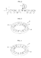
- FIG. 1 is an exploded perspective view illustrating the stator core, the first insulator and the second insulator, and the stator core is formed in a mold and assembled, further, has a state before bending
- FIG. 2 is an assembly view of FIG. 1
- FIG. 3 is a perspective view illustrating the stator core of FIG. 1 , which is bended and is cylindrically rolled, and as a fixing unit according to the first exemplary embodiment of the present disclosure
- FIG. 4 is a perspective view illustrating the stator core of FIG. 1 , which is bended and is cylindrically rolled, and as a fixing unit according to the second exemplary embodiment ofthe present disclosure
- FIG. 5 is a perspective view illustrating the stator core module of FIG. 1 , which is bended and is cylindrically rolled
- FIG. 6 is an enlarged view of the teeth for stator core module in FIG. 5 .
- the stator core of the present invention comprises the stator core module (1) composed of assembly with the stator core body (100), the first insulator (410), and the second insulator (420), and wound by the coil (C, referring FIG. 8 ), and further comprises the fixing units (200) (300) for fixing the bended stator core body (100) as a circular shape.
- the stator core body (100) is formed as one body by mold for plural teeth (110) to be formed protrusively at regular interval in the same direction.
- the stator core body (100) is formed as cylindrical shape in which both ends (101) (102) are combined by bending process for a designed section (A) of right and left around the teeth (110) as shown in FIG. 2 .
- the stator core body (100) has a hook unit (120) having complementary shape around the protrusion of the adjacent teeth (110) in order to maintain a cylindrical shape in the bending process.
- the hook unit (120) has a concavo and convex structure interlocked with each other.
- the hook protrusion (121) is formed at the one end, and the receptive groove (122) is formed at the other end of the hook unit (120).
- the edges of the hook protrusion (121) and the receptive groove (122) are rounded for smooth combination.
- the gapped groove (123) is formed at the position nearby the hook unit (12) to reduce an interference effect of each designed section (A) during the bending of stator core body (100).
- the gapped groove (123), as shown in FIG. 1 has a trench structure having a roughly circular cross section and one end is opened thus this opened end is connected with the hook unit (120).
- the fixing unit (200) is formed at the both ends of the stator core body (100) in order to fix the stator core body (100) as a cylindrical shape, and comprises the fixing protrusion (210) and the fixing groove (220).
- the fixing protrusion (210) is protrusively formed at the one end (101) of the stator core body (100), and is formed to have a roughly square cross section as shown, but it is not limited to the square cross section, further the cross section can have a circular or polygonal shape even though those are not shown.
- the fixing protrusion (210) can have whatever structures if the fixing protrusion (210) is hooked in the separation direction ofthe fixing groove (220).
- the fixing groove (220) is concavely formed as a complementary shape to the fixing protrusion (210) at the other end (102) of the stator core body (100).
- the fixing unit (200) configured in the same manner as above, is fixed by a sliding-fit assembly of the fixing protrusion (210) and the fixing groove (200), and the fixing unit (200) fixes the stator core body (100) as a cylindrical shape by press-in process of minimizing a tolerance between the fixing protrusion (210) and the fixing groove (200).
- the fixing unit (300) comprises, as shown in FIG. 4 and FIG. 5 , a pin groove (310) and a fixing pin (320).
- the pin groove (310) is formed at both ends of the stator core body (100), as shown, and comprises more than two hitching units (311) and an opening unit (312) connected with the hitching unit (311), and prevents the fixing pin (320) from being separated in the perpendicular direction to the direction (Arrow B direction in FIG. 5 ) of which the fixing pin (320) is inserted and assembled in the pin groove (310).
- the pin groove (310) is installed to have a mutually symmetrical shape at the both ends (101) (102) (Referring FIG. 1 ) ofthe stator core body (100).
- the fixing pin (320) has a complementary shape to a shape of the pin groove (310) to be inserted and assembled in the pin groove (310).
- the fixing pin (320) has a bilateral symmetrical shape because the pin groove (310) located at the both ends (101) (102) ofthe stator core body (100) has a mutually symmetrical shape.
- the fixing pin (320) is pressed and assembled in the parallel direction to the arrow B direction of FIG. 6 .
- the pin groove (310) is arranged as a "T” shape, and the fixing pin (320) fixedly inserted in a pair of the pin groove (310) is arranged as a "H" shape, but it is not limited to the described shapes, further the shapes can have whatever shapes if the shape can prevent the separation in the perpendicular direction to the described arrow B direction.
- each corner of the pin groove (310) and the fixing pin (320) are rounded, and are arranged as same thickness with the stator core body (100).
- the fixing unit (300) using the fixing pin (320) By means of the fixing unit (300) using the fixing pin (320), the combination and transportation for motor is easy and the loss of working following combination error of core unit can be reduced because the air gap of each split cores is minimized during the combination of stator core.
- the first insulator (410) and the second insulator (420), as shown in FIG. 1 , FIG. 2 , FIG. 7 , and FIG. 8 , are connected at the upper and the lower ofthe stator core body (100), and prevent a current flowing in the coil (C) wound in the teeth (110) from being transmitted to the stator core body (100).
- the first insulator (410) and the second insulator (420) are arranged as mutually complementary shapes, and assembled with the stator core body (100) at the same time.
- the first insulator (410) and the second insulator (420), as shown in FIG. 1 and FIG. 2 are formed as one body having a line shape by injection molding.
- the first simulator (410) and the second simulator (420) are arranged to be separated from each other by the section wrapping the teeth (110) during the bending process of the stator core body.
- the first insulator (410) and the second insulator (420), as shown in FIG. 1 and FIG. 2 have the bottleneck (411) (421) having within 0.5mm thickness nearby the position of the bending section of the stator core body (100), and the bottleneck (411) (421) is fractured by fatigue during the bending process of the stator core body (100).
- the first No.1 insulator (410a) and the second No.1 insulator (410b), which are attached each other when first created, can form neck unit (N) by separation as shown in FIG. 8 if the stator core module (1) is bended as cylindrical shape.
- stator core for motor for motor
- manufacturing method of stator core for motor will be described in detail according to an exemplary embodiment ofthe present disclosure.
- An object ofthe present invention is to form the stator core body (100), the first insulator (410), and the second insulator (420) as a line shape for the manufacturing of the stator core module (1), and is to form the temporarily assembled stator core module (1), as shown in FIG. 2 , by the combination of the stator core body (100), the first insulator (410), and the second insulator (420).
- one body by mold is formed for plural teeth protrusively at regular interval in the same direction.
- More than one stator core body preferably two stator core bodies (100) are formed by injection or sintering as cylindrical shape in which both ends are combined by bending process for a designed section of right and left around the teeth.
- the opposite surface of the teeth formed is configured to have a circular shape and have an arc shape by a constant interval (S10).
- the first insulator (410) and the second insulator (420) are integrally made by injection molding to have complementary shape to each other, and to wrap a part of stator core body (100) and one end surface of the plural teeth (110) simultaneously.
- the first insulator (410) and the second insulator (420) are made of synthetic resins often used as insulating material (S20).
- the line-shaped stator core module (1) is formed by the assembly with the stator core body (110), the first insulator (410), and the second insulator (420), which all are formed from the S10 stage and the S20 stage, in a line condition which is previous stage of bending.
- the coil (C, Referring FIG. 8 ) is wound on the teeth (110) insulated by the first insulator (410) and the second insulator (420) of the line-shaped stator core module (10) formed from the S30 stage.
- the described coiling more simple coiling can be done comparing to a coiling process that coils on the teeth of an integrated stator core of existing.
- the end of the teeth (110) has a small number of turns, and the other end has a large number of turns.
- stator core module (1) can be improved because it is possible to make a uniform distance (g) with the coil (C) on the adjacent teeth (110) after bending (S40).
- stator core module (1) coiled from the S40 stage, the stator core body (100), the first insulator (410), and the second insulator (420) is fixed by the fixing units (200) (300) arranged ate the both ends of the stator core body after bending the stator core body (100), the first insulator (410), and the second insulator (420) as a circular shape (S50).
- the stage of bending further comprises a stage (S51) of fixing for every teeth by the section successively through the hook unit (120), which is configured nearby the stator core body (100), and has complementary shape around the protrusion of the adjacent teeth, and a stage (S52) of forming the separated neck unit (N) (Referring FIG. 8 ) through the fatigue fracture, which is caused by bending, for the bottleneck (411) (421) of the first insulator (410) and the second insulator (420).
- the cylindrical-shaped stator core can be formed by combination with the another stator core module (1) made from the stage of S10 or S50.
- the cylindrical-shaped stator core body (100) is formed by the combination of the two semicircular-shaped stator core modules (1).
- the stator core body (100) is combined by using just one or two stator core module (1) because there is no difference with a conventional combination process using split core if the number of the stator core module (1) increases.
Landscapes
- Engineering & Computer Science (AREA)
- Power Engineering (AREA)
- Manufacturing & Machinery (AREA)
- Iron Core Of Rotating Electric Machines (AREA)
- Manufacture Of Motors, Generators (AREA)
Abstract
Description
- The present invention relates stator core for motor and manufacturing method thereof
- Generally, stator core for motor is formed by coiling plural teeth protruded from an inner circumferential surface after a metal core body is configured as a cylindrical shape.
- Recently the stator core needs a miniaturization and weight lightening according to a miniaturization of motor, thus a forming the stator core by laminating a thin metal plate with constant thickness or forming the cylindrical shaped stator core by combining a roughly "T" shaped a split core having one teeth is more often used than a conventional forming method using the stator core of one body.
- But for the laminating stator core, there is a complication that plural metal plates undergo press working with the same configuration, and then the laminating process should be done separately. Further for the split core, there is a complication that stator core should be formed as a cylindrical shape by a fitting combination for the connecting part of split core using an extra adhesion or arranging a complementary shape due to an air gap in a assembly position for each split core during a combination process of a cylindrical shaped stator core by combination of each split core after each split core is formed by molding or sintering.
- Recently for the solution of the described complication, the art which assembles more than one laminated unit core with completion of bending after laminating plural unit core and bending laminated unit core simultaneously, to be ring shaped stator core is stated in the Korean Patent No.
2008-0078944, released on August 29, 2008 - But according to this composition, product defects by the separation of core assembly are mostly likely to occur in a assembly process of stator core after bending, and also there is a problem that if the assembled parts are not firmly fixed, the efficiency for motor can fall or poor performance can occur.
- Accordingly, an object of the present invention is to provide the stator core for motor, which has improved structure in order to compose a cylindrical stator core by rolling one integrally formed body, and firmly compose an assembly structure in the assembly units facing each other.
- The stator core for motor by the present invention comprises that more than one stator core body, which is formed as one body by mold for plural teeth to be formed protrusively at regular interval in the same direction, and is formed as cylindrical shape in which both ends are combined by bending process for a designed section of right and left around the teeth; a fixing unit, which is arranged at both ends of the stator core body and fixes the stator core body to be a cylindrical shape; a first insulator, which is integrally formed by mold in order to wrap a part of the stator core body and a side surface of plural teeth simultaneously; and a second insulator, which is arranged to have a form corresponding to the first insulator, and which is integrally formed by mold in order to wrap a part of the stator core body and a side surface of plural teeth simultaneously through the assembly with the first insulator, wherein the first simulator and the second simulator are separated from each other by the section wrapping the teeth during the bending process of the stator core body.
- Preferably, but not necessarily, the first insulator and the second insulator have the bottleneck having within 0.5mm thickness nearby the position of the bending section of the stator core body, and the bottleneck is fractured by fatigue during the bending process of the stator core body.
- Preferably, but not necessarily, the fixing unit comprises a fixing protrusion, which is protrusively formed at one side end of the stator core body; and a fixing groove, which is concavely formed as complementary shape to the fixing protrusion at the other end of the stator core body.
- Further, the fixing unit comprises a pin groove, which is formed at both ends of the stator core body; and a fixing pin, which is fitted adjustably to the pin groove. The pin groove comprises more than two hitching units; and an opening unit connected with the hitching unit, and can prevents the fixing pin from being separated in the perpendicular direction to the direction of which the fixing pin is inserted and assembled in the pin groove, herein the pin groove is arranged as a "T" shape, and the fixing pin fixedly inserted in a pair of the pin groove is arranged as a "H" shape.
- Preferably, but not necessarily, each corner of the fixing pin and pin groove are rounded, and the fixing pin is arranged as same thickness with the stator core body.
- Preferably, but not necessarily, the stator core body has a hook unit having complementary shape around the protrusion of the adjacent teeth in order to maintain a cylindrical shape in the bending process.
- Preferably, but not necessarily, the hook unit has the rounded edge of which the concavo and convex structure interlocked with each other, and the gapped groove is formed at the position nearby the hook unit to reduce an interference effect during the bending of stator core body.
- According to an exemplary embodiment of the present disclosure, the manufacturing method of stator core for motor comprises a stage of injection molding for more than one stator core body, which is formed as one body by mold for plural teeth to be formed protrusively at regular interval in the same direction, and is formed as cylindrical shape in which both ends are combined by bending process for a designed section of right and left around the teeth; a stage of injection molding for a first insulator, which is integrally formed by mold in order to wrap a part of the stator core body and a side surface of plural teeth simultaneously, and for a second insulator, which is arranged to have a form corresponding to the first insulator, and which is integrally formed by mold in order to wrap a part of the stator core body and a side surface of plural teeth simultaneously through the assembly with the first insulator; a stage of assembly for the molded stator core body, the first insulator, and the second insulator in a linear condition; a stage of coiling around the teeth insulated by the first insulator and the second insulator; a stage of fixing the coiled stator core body, the first insulator, and the second insulator by using the fixing unit arranged at the both ends of the stator core body after bending the coiled stator core body, the first insulator, and the second insulator as a circular shape.
- The stage of bending further comprises a stage of fixing for every teeth by the section successively through the hook unit, which is configured nearby the stator core body, and has complementary shape around the protrusion of the adjacent teeth.
- The stage of coiling comprises a stage of coiling the teeth in order to maintain the constant distance between the coils wound around the teeth of stator core body having a cylindrical shape by the bending process.
- Preferably, but not necessarily, the manufacturing method of stator core for motor comprises a stage of forming a cylindrical shaped stator core by assembly with another stator core module formed from the equal process, if the stator core module formed by the assembly and bending of the stator core body, the first insulator, and the second insulator, has a semicircular shape.
- The advantage according to the present invention is that the fixing ability and assembly efficiency can be improved because the reliability of assembly part of stator core made by rolling one integrally formed body is improved.
- Further, the combination and transportation for motor is easy and the loss of working following combination error of core unit can be reduced because the air gap of each split cores is minimized during the combination of stator core.
-
-
FIG. 1 is an exploded perspective view illustrating the stator core, the first insulator and the second insulator. The stator core is formed in a mold and assembled, further, has a state before bending; -
FIG. 2 is an assembly view ofFIG. 1 ; -
FIG. 3 is a perspective view illustrating the stator core ofFIG. 1 , which is bended and is cylindrically rolled, and as a fixing unit according to the first exemplary embodiment of the present disclosure; -
FIG. 4 is a perspective view illustrating the stator core ofFIG. 1 , which is bended and is cylindrically rolled, and as a fixing unit according to the second exemplary embodiment of the present disclosure; -
FIG. 5 is a perspective view illustrating the stator core module ofFIG. 1 , which is bended and is cylindrically rolled; -
FIG. 6 is a perspective view of the stator core module according to an exemplary embodiment ofthe present disclosure; -
FIG. 7 is an exploded perspective view ofFIG. 6 ; -
FIG. 8 is a plan view ofthe stator core ofFIG. 6 and an enlarged view of the teeth; and -
FIG. 9 andFIG 10 are flow charts illustrating the manufacturing method of the stator core for the motor according to an exemplary embodiment ofthe present disclosure. - Hereinafter, the stator core for motor and manufacturing method thereof will be described in detail with reference to the accompanying drawings.
-
FIG. 1 is an exploded perspective view illustrating the stator core, the first insulator and the second insulator, and the stator core is formed in a mold and assembled, further, has a state before bending,FIG. 2 is an assembly view ofFIG. 1 ,FIG. 3 is a perspective view illustrating the stator core ofFIG. 1 , which is bended and is cylindrically rolled, and as a fixing unit according to the first exemplary embodiment of the present disclosure,FIG. 4 is a perspective view illustrating the stator core ofFIG. 1 , which is bended and is cylindrically rolled, and as a fixing unit according to the second exemplary embodiment ofthe present disclosure,FIG. 5 is a perspective view illustrating the stator core module ofFIG. 1 , which is bended and is cylindrically rolled, -
FIG. 6 is an enlarged view of the teeth for stator core module inFIG. 5 . - As shown in
FIG. 1 orFIG. 4 , the stator core of the present invention comprises the stator core module (1) composed of assembly with the stator core body (100), the first insulator (410), and the second insulator (420), and wound by the coil (C, referringFIG. 8 ), and further comprises the fixing units (200) (300) for fixing the bended stator core body (100) as a circular shape. - The stator core body (100) is formed as one body by mold for plural teeth (110) to be formed protrusively at regular interval in the same direction. Preferably, but not necessarily, the stator core body (100) is formed as cylindrical shape in which both ends (101) (102) are combined by bending process for a designed section (A) of right and left around the teeth (110) as shown in
FIG. 2 . - Preferably, but not necessarily, the stator core body (100) has a hook unit (120) having complementary shape around the protrusion of the adjacent teeth (110) in order to maintain a cylindrical shape in the bending process.
- The hook unit (120) has a concavo and convex structure interlocked with each other. The hook protrusion (121) is formed at the one end, and the receptive groove (122) is formed at the other end of the hook unit (120). Preferably, but not necessarily, the edges of the hook protrusion (121) and the receptive groove (122) are rounded for smooth combination.
- Further, the gapped groove (123) is formed at the position nearby the hook unit (12) to reduce an interference effect of each designed section (A) during the bending of stator core body (100). Preferably, but not necessarily, the gapped groove (123), as shown in
FIG. 1 , has a trench structure having a roughly circular cross section and one end is opened thus this opened end is connected with the hook unit (120). - According to the first exemplary embodiment of the present disclosure, the fixing unit (200), as shown in
FIG. 3 , is formed at the both ends of the stator core body (100) in order to fix the stator core body (100) as a cylindrical shape, and comprises the fixing protrusion (210) and the fixing groove (220). - The fixing protrusion (210) is protrusively formed at the one end (101) of the stator core body (100), and is formed to have a roughly square cross section as shown, but it is not limited to the square cross section, further the cross section can have a circular or polygonal shape even though those are not shown. The fixing protrusion (210) can have whatever structures if the fixing protrusion (210) is hooked in the separation direction ofthe fixing groove (220).
- The fixing groove (220) is concavely formed as a complementary shape to the fixing protrusion (210) at the other end (102) of the stator core body (100).
- According to the first exemplary embodiment of the present disclosure, the fixing unit (200) configured in the same manner as above, is fixed by a sliding-fit assembly of the fixing protrusion (210) and the fixing groove (200), and the fixing unit (200) fixes the stator core body (100) as a cylindrical shape by press-in process of minimizing a tolerance between the fixing protrusion (210) and the fixing groove (200).
- According to the second exemplary embodiment of the present disclosure, the fixing unit (300) comprises, as shown in
FIG. 4 andFIG. 5 , a pin groove (310) and a fixing pin (320). - The pin groove (310) is formed at both ends of the stator core body (100), as shown, and comprises more than two hitching units (311) and an opening unit (312) connected with the hitching unit (311), and prevents the fixing pin (320) from being separated in the perpendicular direction to the direction (Arrow B direction in
FIG. 5 ) of which the fixing pin (320) is inserted and assembled in the pin groove (310). - According to an exemplary embodiment of the present disclosure, preferably, but not necessarily, the pin groove (310) is installed to have a mutually symmetrical shape at the both ends (101) (102) (Referring
FIG. 1 ) ofthe stator core body (100). - The fixing pin (320) has a complementary shape to a shape of the pin groove (310) to be inserted and assembled in the pin groove (310). Preferably, but not necessarily, the fixing pin (320) has a bilateral symmetrical shape because the pin groove (310) located at the both ends (101) (102) ofthe stator core body (100) has a mutually symmetrical shape. The fixing pin (320) is pressed and assembled in the parallel direction to the arrow B direction of
FIG. 6 . - According to an exemplary embodiment of the present disclosure, the pin groove (310) is arranged as a "T" shape, and the fixing pin (320) fixedly inserted in a pair of the pin groove (310) is arranged as a "H" shape, but it is not limited to the described shapes, further the shapes can have whatever shapes if the shape can prevent the separation in the perpendicular direction to the described arrow B direction.
- Further preferably, but not necessarily, each corner of the pin groove (310) and the fixing pin (320) are rounded, and are arranged as same thickness with the stator core body (100).
- By means of the fixing unit (300) using the fixing pin (320), the combination and transportation for motor is easy and the loss of working following combination error of core unit can be reduced because the air gap of each split cores is minimized during the combination of stator core.
- The first insulator (410) and the second insulator (420), as shown in
FIG. 1 ,FIG. 2 ,FIG. 7 , andFIG. 8 , are connected at the upper and the lower ofthe stator core body (100), and prevent a current flowing in the coil (C) wound in the teeth (110) from being transmitted to the stator core body (100). - The first insulator (410) and the second insulator (420) are arranged as mutually complementary shapes, and assembled with the stator core body (100) at the same time. Preferably, but not necessarily, for the above described assembly, the first insulator (410) and the second insulator (420), as shown in
FIG. 1 andFIG. 2 , are formed as one body having a line shape by injection molding. - Preferably, but not necessarily, the first simulator (410) and the second simulator (420) are arranged to be separated from each other by the section wrapping the teeth (110) during the bending process of the stator core body.
- Preferably, but not necessarily, the first insulator (410) and the second insulator (420), as shown in
FIG. 1 andFIG. 2 , have the bottleneck (411) (421) having within 0.5mm thickness nearby the position of the bending section of the stator core body (100), and the bottleneck (411) (421) is fractured by fatigue during the bending process of the stator core body (100). - According to the described composition, the first No.1 insulator (410a) and the second No.1 insulator (410b), which are attached each other when first created, can form neck unit (N) by separation as shown in
FIG. 8 if the stator core module (1) is bended as cylindrical shape. - Hereinafter, the manufacturing method of stator core for motor will be described in detail according to an exemplary embodiment ofthe present disclosure.
- An object ofthe present invention is to form the stator core body (100), the first insulator (410), and the second insulator (420) as a line shape for the manufacturing of the stator core module (1), and is to form the temporarily assembled stator core module (1), as shown in
FIG. 2 , by the combination of the stator core body (100), the first insulator (410), and the second insulator (420). - First, one body by mold is formed for plural teeth protrusively at regular interval in the same direction. More than one stator core body, preferably two stator core bodies (100) are formed by injection or sintering as cylindrical shape in which both ends are combined by bending process for a designed section of right and left around the teeth. The opposite surface of the teeth formed is configured to have a circular shape and have an arc shape by a constant interval (S10).
- The first insulator (410) and the second insulator (420) are integrally made by injection molding to have complementary shape to each other, and to wrap a part of stator core body (100) and one end surface of the plural teeth (110) simultaneously. Preferably, but necessarily, the first insulator (410) and the second insulator (420) are made of synthetic resins often used as insulating material (S20).
- The line-shaped stator core module (1) is formed by the assembly with the stator core body (110), the first insulator (410), and the second insulator (420), which all are formed from the S10 stage and the S20 stage, in a line condition which is previous stage of bending.
- As a next stage, the coil (C, Referring
FIG. 8 ) is wound on the teeth (110) insulated by the first insulator (410) and the second insulator (420) of the line-shaped stator core module (10) formed from the S30 stage. Though the described coiling, more simple coiling can be done comparing to a coiling process that coils on the teeth of an integrated stator core of existing. In other words, in order to make a uniform distance (g) (ReferringFIG. 8 ) with the coil on the adjacent teeth (110) after bending, the end of the teeth (110) has a small number of turns, and the other end has a large number of turns. In the pas ways, it is difficult to wind a coil due to a small space between the teeth protruding toward the center because the stator core is already formed as a cylindrical shape. But it is easy to wind a coil as much as wanted by location, if a coil is wound in an unfolded condition as a line-shaped. Further, the space factor of stator core module (1) can be improved because it is possible to make a uniform distance (g) with the coil (C) on the adjacent teeth (110) after bending (S40). - For the stator core module (1) coiled from the S40 stage, the stator core body (100), the first insulator (410), and the second insulator (420) is fixed by the fixing units (200) (300) arranged ate the both ends of the stator core body after bending the stator core body (100), the first insulator (410), and the second insulator (420) as a circular shape (S50).
- The stage of bending further comprises a stage (S51) of fixing for every teeth by the section successively through the hook unit (120), which is configured nearby the stator core body (100), and has complementary shape around the protrusion of the adjacent teeth, and a stage (S52) of forming the separated neck unit (N) (Referring
FIG. 8 ) through the fatigue fracture, which is caused by bending, for the bottleneck (411) (421) of the first insulator (410) and the second insulator (420). - If the stator core module (1), which is formed by the assembly and bending of the stator core body (100), the first insulator (410), and the second insulator (420), is arranged as a semicircular shape, the cylindrical-shaped stator core can be formed by combination with the another stator core module (1) made from the stage of S10 or S50. According to an exemplary embodiment of the present disclosure, the cylindrical-shaped stator core body (100) is formed by the combination of the two semicircular-shaped stator core modules (1). But it is not limited to the above described, further it is possible to combine more than two stator core modules (1) as needed. Preferably, but not necessarily, the stator core body (100) is combined by using just one or two stator core module (1) because there is no difference with a conventional combination process using split core if the number of the stator core module (1) increases.
- Although the present disclosure has been described with reference to a number of illustrative embodiments thereof, it should be understood that numerous other modifications and embodiments can be devised by those skilled in the art that will fall within the spirit and scope of the principles ofthis disclosure.
- More particularly, various variations and modifications are possible in the component parts and/or arrangements of subject combination arrangement within the scope of the disclosure, the drawings and the appended claims. In addition to variations and modifications in the component parts and/or arrangements, alternative uses will also be apparent to those skilled in the art.
Claims (15)
- Stator core for motor and manufacturing method thereof, the stator core comprises:more than one stator core body, which is formed as one body by mold for plural teeth to be formed protrusively at regular interval in the same direction, and is formed as cylindrical shape in which both ends are combined by bending process for a designed section of right and left around the teeth.a fixing unit, which is arranged at both ends of the stator core body and fixes the stator core body to be a cylindrical shape;a first insulator, which is integrally formed by mold in order to wrap a part of the stator core body and a side surface ofplural teeth simultaneously; anda second insulator, which is arranged to have a form corresponding to the first insulator, and which is integrally formed by mold in order to wrap a part of the stator core body and a side surface of plural teeth simultaneously through the assembly with the first insulator, wherein the first simulator and the second simulator are separated from each other by the section wrapping the teeth during the bending process of the stator core body
- The stator core of claim 1, wherein the first insulator and the second insulator have the bottleneck having within 0.5mm thickness nearby the position of the bending section of the stator core body, and the bottleneck is fractured by fatigue during the bending process of the stator core body.
- The stator core of claim 1, wherein the fixing unit comprises:a fixing protrusion, which is protrusively formed at one side end ofthe stator core body;a fixing groove, which is concavely formed as complementary shape to the fixing protrusion at the other end ofthe stator core body.
- The stator core of claim 1, wherein the fixing unit comprises:a pin groove, which is formed at both ends of the stator core body;a fixing pin, which is fitted adjustably to the pin groove.
- The stator core of claim 4, wherein the pin groove prevents the fixing pin from being separated in the perpendicular direction to the direction of which the fixing pin is inserted and assembled in the pin groove, and comprises:more than two hitching units;an opening unit connected with the hitching unit.
- The stator core of claim 4, wherein the pin groove is arranged as a "T" shape, and the fixing pin fixedly inserted in a pair of the pin groove is arranged as a "H" shape.
- The stator core of claim 6, wherein each corner of the fixing pin and pin groove are rounded.
- The stator core of claim 4, wherein the fixing pin is arranged as same thickness with the stator core body.
- The stator core of claim 1, wherein the stator core body has a hook unit having complementary shape around the protrusion of the adjacent teeth in order to maintain a cylindrical shape in the bending process.
- The stator core of claim 9, wherein the hook unit has the rounded edge of which the concavo and convex structure interlocked with each other.
- The stator core of claim 9, wherein the gapped groove is formed at the position nearby the hook unit to reduce an interference effect during the bending of stator core body.
- Stator core for motor and manufacturing method thereof, the manufacturing method thereof comprises:a stage of injection molding for more than one stator core body, which is formed as one body by mold for plural teeth to be formed protrusively at regular interval in the same direction, and is formed as cylindrical shape in which both ends are combined by bending process for a designed section of right and left around the teeth.a stage of injection molding for a first insulator, which is integrally formed by mold in order to wrap a part of the stator core body and a side surface of plural teeth simultaneously, and for a second insulator, which is arranged to have a form corresponding to the first insulator, and which is integrally formed by mold in order to wrap a part of the stator core body and a side surface ofplural teeth simultaneously through the assembly with the first insulatora stage of assembly for the molded stator core body, the first insulator, and the second insulator in a linear condition.a stage of coiling around the teeth insulated by the first insulator and the second insulator.a stage of fixing the coiled stator core body, the first insulator, and the second insulator by using the fixing unit arranged at the both ends of the stator core body after bending the coiled stator core body, the first insulator, and the second insulator as a circular shape.
- The manufacturing method thereof of claim 12, wherein the stage of bending further comprises a stage of fixing for every teeth by the section successively through the hook unit, which is configured nearby the stator core body, and has complementary shape around the protrusion ofthe adjacent teeth.
- The manufacturing method thereof of claim 12, wherein the stage of coiling comprises a stage of coiling the teeth in order to maintain the constant distance between the coil wound around the teeth of stator core body having a cylindrical shape by the bending process.
- The manufacturing method thereof claim 12, it further comprises a stage of forming a cylindrical shaped stator core by assembly with another stator core module formed from the equal process, if the stator core module formed by the assembly and bending of the stator core body, the first insulator, and the second insulator, has a semicircular shape.
Priority Applications (1)
| Application Number | Priority Date | Filing Date | Title |
|---|---|---|---|
| EP20177269.6A EP3723250B1 (en) | 2011-10-20 | 2012-08-06 | Stator core for motor and manufacturing method thereof |
Applications Claiming Priority (1)
| Application Number | Priority Date | Filing Date | Title |
|---|---|---|---|
| KR1020110107389A KR101876226B1 (en) | 2011-10-20 | 2011-10-20 | Stator core for Motor and manufacturing method thereof |
Related Child Applications (2)
| Application Number | Title | Priority Date | Filing Date |
|---|---|---|---|
| EP20177269.6A Division EP3723250B1 (en) | 2011-10-20 | 2012-08-06 | Stator core for motor and manufacturing method thereof |
| EP20177269.6A Division-Into EP3723250B1 (en) | 2011-10-20 | 2012-08-06 | Stator core for motor and manufacturing method thereof |
Publications (3)
| Publication Number | Publication Date |
|---|---|
| EP2584680A2 true EP2584680A2 (en) | 2013-04-24 |
| EP2584680A3 EP2584680A3 (en) | 2017-06-28 |
| EP2584680B1 EP2584680B1 (en) | 2020-07-15 |
Family
ID=46679175
Family Applications (2)
| Application Number | Title | Priority Date | Filing Date |
|---|---|---|---|
| EP12179366.5A Active EP2584680B1 (en) | 2011-10-20 | 2012-08-06 | Stator core for motor and manufacturing method thereof |
| EP20177269.6A Active EP3723250B1 (en) | 2011-10-20 | 2012-08-06 | Stator core for motor and manufacturing method thereof |
Family Applications After (1)
| Application Number | Title | Priority Date | Filing Date |
|---|---|---|---|
| EP20177269.6A Active EP3723250B1 (en) | 2011-10-20 | 2012-08-06 | Stator core for motor and manufacturing method thereof |
Country Status (4)
| Country | Link |
|---|---|
| US (2) | US9473005B2 (en) |
| EP (2) | EP2584680B1 (en) |
| JP (1) | JP6166025B2 (en) |
| KR (1) | KR101876226B1 (en) |
Cited By (3)
| Publication number | Priority date | Publication date | Assignee | Title |
|---|---|---|---|---|
| CN104362810A (en) * | 2014-10-31 | 2015-02-18 | 广东威灵电机制造有限公司 | Manufacturing method of stator laminations |
| CN104578613A (en) * | 2014-12-25 | 2015-04-29 | 广东威灵电机制造有限公司 | Stator manufacturing method |
| EP3035491A4 (en) * | 2013-11-08 | 2018-05-30 | Samsung Electronics Co., Ltd. | Motor, manufacturing method thereof, and washing machine |
Families Citing this family (16)
| Publication number | Priority date | Publication date | Assignee | Title |
|---|---|---|---|---|
| DE102011085636A1 (en) * | 2011-11-02 | 2013-05-02 | Hamilton Bonaduz Ag | Linear motor with multiple sensor units and modular stator construction |
| US9143015B2 (en) | 2012-05-23 | 2015-09-22 | Black & Decker Inc. | Brush holder for a brush assembly for a power tool motor |
| WO2014203849A1 (en) * | 2013-06-21 | 2014-12-24 | 日本電産サーボ株式会社 | Rotating electric machine and rotating electric machine manufacturing method |
| JP5980185B2 (en) * | 2013-09-20 | 2016-08-31 | 日本電産テクノモータ株式会社 | Resin molded stator and manufacturing method thereof |
| DE112013007578T5 (en) * | 2013-11-08 | 2016-08-18 | Mitsubishi Electric Corporation | Stator of a rotating electric machine and rotary electric machine |
| KR102604381B1 (en) * | 2016-07-07 | 2023-11-21 | 엘지이노텍 주식회사 | Stator Unit, Stator and Motor having the same |
| FR3072517B1 (en) * | 2017-10-17 | 2020-12-18 | Moving Magnet Tech | TOROIDAL POLYPHASED ELECTRIC MACHINE |
| US11456629B2 (en) * | 2017-12-07 | 2022-09-27 | Kyocera Industrial Tools Corporation | Stator with divided cores connected circumferentially |
| CN108270330B (en) * | 2017-12-29 | 2024-10-22 | 日本电产芝浦(浙江)有限公司 | Stator core bending device, stator core bending method and stator core |
| EP3745559B1 (en) * | 2019-05-27 | 2022-03-09 | Magnax Bv | Stator for an axial flux machine |
| KR102784711B1 (en) * | 2020-05-21 | 2025-03-21 | 엘지전자 주식회사 | Electric motor and cleaner having the same, manufacturing method for electric motor |
| JP7637495B2 (en) * | 2020-11-20 | 2025-02-28 | ミネベアミツミ株式会社 | Motor |
| JP7705237B2 (en) * | 2020-11-20 | 2025-07-09 | ミネベアミツミ株式会社 | Motor |
| DE102021106186A1 (en) * | 2021-03-15 | 2022-09-15 | Ebm-Papst Mulfingen Gmbh & Co. Kg | Modular, segmented stator package |
| IT202200014590A1 (en) * | 2022-07-12 | 2024-01-12 | Marelli Europe Spa | STATOR WITH BAR WINDING AND FLUID COOLING FOR A ROTARY ELECTRIC MACHINE |
| JP7814336B2 (en) * | 2023-03-01 | 2026-02-16 | 三菱電機株式会社 | Stator manufacturing method, electric motor manufacturing method |
Citations (1)
| Publication number | Priority date | Publication date | Assignee | Title |
|---|---|---|---|---|
| KR20080078944A (en) | 2007-02-26 | 2008-08-29 | 엘지전자 주식회사 | Motor core and manufacturing method for the same |
Family Cites Families (20)
| Publication number | Priority date | Publication date | Assignee | Title |
|---|---|---|---|---|
| US2502185A (en) * | 1949-03-29 | 1950-03-28 | Gen Electric | Stator for universal electric motors |
| US4366198A (en) * | 1981-03-24 | 1982-12-28 | Rca Corporation | Sheet material separation construction |
| JPH0348343U (en) * | 1989-09-18 | 1991-05-09 | ||
| JPH069349U (en) * | 1991-09-05 | 1994-02-04 | 日本電産株式会社 | Electric motor stator core |
| JP2933807B2 (en) * | 1993-08-23 | 1999-08-16 | 株式会社三協精機製作所 | Core of rotating electric machine |
| JP3017085B2 (en) * | 1995-11-02 | 2000-03-06 | 三菱電機株式会社 | Rotating electric machine and method of manufacturing the same |
| JP3680482B2 (en) | 1997-03-28 | 2005-08-10 | 松下電器産業株式会社 | Electric motor stator constituent member, electric motor stator, electric motor manufacturing method |
| JP2000014057A (en) | 1998-06-18 | 2000-01-14 | Nippon Densan Corp | Armature structure of dynamo-electric machine, and its manufacture |
| JP3451263B2 (en) | 1998-08-28 | 2003-09-29 | 三菱電機株式会社 | Stator |
| JP2001045684A (en) | 1999-07-30 | 2001-02-16 | Hitachi Ltd | Manufacturing method of motor stator core |
| JP2001136700A (en) * | 1999-11-02 | 2001-05-18 | Mitsubishi Electric Corp | Stator and stator manufacturing method |
| JP2001211574A (en) | 2000-01-20 | 2001-08-03 | Techno Excel Co Ltd | Stator core for motor |
| JP3674599B2 (en) | 2002-05-02 | 2005-07-20 | 日本電産シバウラ株式会社 | Electric motor core, electric motor, and method for manufacturing electric motor core |
| KR100454556B1 (en) * | 2002-05-09 | 2004-11-05 | 주식회사 미크로닉 | Stator for BLDC Motor Using Segmental Stator Cores, Fabricating Method thereof and BLDC Motor Using the Same |
| US6919665B2 (en) * | 2003-09-30 | 2005-07-19 | Nidec Shibaura Corporation | Stator core, an electric motor in which it is utilized, and method of manufacturing a stator core |
| JP4150397B2 (en) | 2005-11-16 | 2008-09-17 | 株式会社三井ハイテック | Laminated iron core and method for manufacturing the same |
| JP2007151312A (en) | 2005-11-29 | 2007-06-14 | Fujitsu General Ltd | Induction motor |
| JP4711877B2 (en) * | 2006-04-13 | 2011-06-29 | 株式会社山田製作所 | Method for manufacturing sintered core connection structure and sintered core connection structure |
| JP4948474B2 (en) * | 2008-05-16 | 2012-06-06 | 株式会社富士通ゼネラル | Electric motor |
| JP5601799B2 (en) | 2009-07-10 | 2014-10-08 | パナソニック株式会社 | Stator and stator manufacturing method |
-
2011
- 2011-10-20 KR KR1020110107389A patent/KR101876226B1/en not_active Expired - Fee Related
-
2012
- 2012-08-06 US US13/567,835 patent/US9473005B2/en active Active
- 2012-08-06 EP EP12179366.5A patent/EP2584680B1/en active Active
- 2012-08-06 EP EP20177269.6A patent/EP3723250B1/en active Active
- 2012-08-31 JP JP2012190992A patent/JP6166025B2/en active Active
-
2016
- 2016-08-25 US US15/247,312 patent/US9755488B2/en active Active
Patent Citations (1)
| Publication number | Priority date | Publication date | Assignee | Title |
|---|---|---|---|---|
| KR20080078944A (en) | 2007-02-26 | 2008-08-29 | 엘지전자 주식회사 | Motor core and manufacturing method for the same |
Cited By (6)
| Publication number | Priority date | Publication date | Assignee | Title |
|---|---|---|---|---|
| EP3035491A4 (en) * | 2013-11-08 | 2018-05-30 | Samsung Electronics Co., Ltd. | Motor, manufacturing method thereof, and washing machine |
| US10673289B2 (en) | 2013-11-08 | 2020-06-02 | Samsung Electronics Co., Ltd. | Motor with stiffened stator core, manufacturing method thereof, and washing machine including the motor |
| CN104362810A (en) * | 2014-10-31 | 2015-02-18 | 广东威灵电机制造有限公司 | Manufacturing method of stator laminations |
| CN104362810B (en) * | 2014-10-31 | 2017-06-13 | 广东威灵电机制造有限公司 | The manufacture method of stator punching |
| CN104578613A (en) * | 2014-12-25 | 2015-04-29 | 广东威灵电机制造有限公司 | Stator manufacturing method |
| CN104578613B (en) * | 2014-12-25 | 2017-09-19 | 广东威灵电机制造有限公司 | The manufacture method of stator |
Also Published As
| Publication number | Publication date |
|---|---|
| US20130099604A1 (en) | 2013-04-25 |
| US9755488B2 (en) | 2017-09-05 |
| JP6166025B2 (en) | 2017-07-19 |
| KR20130043343A (en) | 2013-04-30 |
| KR101876226B1 (en) | 2018-07-09 |
| EP3723250B1 (en) | 2021-10-20 |
| US20160365778A1 (en) | 2016-12-15 |
| EP3723250A1 (en) | 2020-10-14 |
| US9473005B2 (en) | 2016-10-18 |
| JP2013090561A (en) | 2013-05-13 |
| EP2584680B1 (en) | 2020-07-15 |
| EP2584680A3 (en) | 2017-06-28 |
Similar Documents
| Publication | Publication Date | Title |
|---|---|---|
| EP2584680B1 (en) | Stator core for motor and manufacturing method thereof | |
| CN101621221B (en) | Motor and method of manufacturing same | |
| US9343221B2 (en) | Resin-mold core and reactor using the same | |
| US9705386B2 (en) | Laminated core for motor and method for manufacturing the same | |
| KR101345029B1 (en) | Method of manufacturing molded stator of dynamo electric machine | |
| JP2013197567A (en) | Reactor and manufacturing method of the same | |
| US20160036187A1 (en) | Manufacturing method of bus bar unit | |
| US10594174B2 (en) | Tool and method for use in assembling a stator assembly of an electric machine | |
| KR20140109997A (en) | Coil manufacturing method | |
| JP5505661B2 (en) | Manufacturing method of electric motor | |
| CN107710557A (en) | The stator of motor | |
| JP5212129B2 (en) | Manufacturing method of laminated core and manufacturing jig thereof | |
| CN103053099A (en) | Stator of an electrical machine | |
| KR101958648B1 (en) | Manufactruing method of plate secondary coil assembly for transformer | |
| WO2015087128A2 (en) | Insulator and stator | |
| EP2711948A2 (en) | Production method for a figure-of-eight-shaped laminated coil | |
| US20070194652A1 (en) | Dynamoelectric stator core and method for manufacture thereof | |
| JP5860767B2 (en) | Coil manufacturing method | |
| KR102173625B1 (en) | Motor core with three split stacked cores | |
| JP2021086953A (en) | Coil assembly and transformer with the same | |
| JP2007166759A (en) | Stator, manufacturing method thereof and electric motor using the stator | |
| JP6432431B2 (en) | Coil component and method for forming coil component | |
| JP2013251997A (en) | Method for manufacturing coil | |
| JP2021012953A (en) | Reactor bobbin, reactor, and manufacturing method of reactor | |
| CN112185669A (en) | Framework for reactor, reactor and manufacturing method of reactor |
Legal Events
| Date | Code | Title | Description |
|---|---|---|---|
| PUAI | Public reference made under article 153(3) epc to a published international application that has entered the european phase |
Free format text: ORIGINAL CODE: 0009012 |
|
| AK | Designated contracting states |
Kind code of ref document: A2 Designated state(s): AL AT BE BG CH CY CZ DE DK EE ES FI FR GB GR HR HU IE IS IT LI LT LU LV MC MK MT NL NO PL PT RO RS SE SI SK SM TR |
|
| AX | Request for extension of the european patent |
Extension state: BA ME |
|
| RAP1 | Party data changed (applicant data changed or rights of an application transferred) |
Owner name: LG INNOTEK CO., LTD. |
|
| PUAL | Search report despatched |
Free format text: ORIGINAL CODE: 0009013 |
|
| AK | Designated contracting states |
Kind code of ref document: A3 Designated state(s): AL AT BE BG CH CY CZ DE DK EE ES FI FR GB GR HR HU IE IS IT LI LT LU LV MC MK MT NL NO PL PT RO RS SE SI SK SM TR |
|
| AX | Request for extension of the european patent |
Extension state: BA ME |
|
| RIC1 | Information provided on ipc code assigned before grant |
Ipc: H02K 15/02 20060101AFI20170524BHEP Ipc: H02K 1/14 20060101ALI20170524BHEP Ipc: H02K 3/34 20060101ALI20170524BHEP |
|
| STAA | Information on the status of an ep patent application or granted ep patent |
Free format text: STATUS: REQUEST FOR EXAMINATION WAS MADE |
|
| 17P | Request for examination filed |
Effective date: 20171205 |
|
| RBV | Designated contracting states (corrected) |
Designated state(s): AL AT BE BG CH CY CZ DE DK EE ES FI FR GB GR HR HU IE IS IT LI LT LU LV MC MK MT NL NO PL PT RO RS SE SI SK SM TR |
|
| STAA | Information on the status of an ep patent application or granted ep patent |
Free format text: STATUS: EXAMINATION IS IN PROGRESS |
|
| 17Q | First examination report despatched |
Effective date: 20181122 |
|
| GRAP | Despatch of communication of intention to grant a patent |
Free format text: ORIGINAL CODE: EPIDOSNIGR1 |
|
| STAA | Information on the status of an ep patent application or granted ep patent |
Free format text: STATUS: GRANT OF PATENT IS INTENDED |
|
| INTG | Intention to grant announced |
Effective date: 20200128 |
|
| GRAS | Grant fee paid |
Free format text: ORIGINAL CODE: EPIDOSNIGR3 |
|
| GRAA | (expected) grant |
Free format text: ORIGINAL CODE: 0009210 |
|
| STAA | Information on the status of an ep patent application or granted ep patent |
Free format text: STATUS: THE PATENT HAS BEEN GRANTED |
|
| AK | Designated contracting states |
Kind code of ref document: B1 Designated state(s): AL AT BE BG CH CY CZ DE DK EE ES FI FR GB GR HR HU IE IS IT LI LT LU LV MC MK MT NL NO PL PT RO RS SE SI SK SM TR |
|
| REG | Reference to a national code |
Ref country code: CH Ref legal event code: EP Ref country code: GB Ref legal event code: FG4D |
|
| REG | Reference to a national code |
Ref country code: IE Ref legal event code: FG4D |
|
| REG | Reference to a national code |
Ref country code: DE Ref legal event code: R096 Ref document number: 602012071234 Country of ref document: DE |
|
| REG | Reference to a national code |
Ref country code: AT Ref legal event code: REF Ref document number: 1292076 Country of ref document: AT Kind code of ref document: T Effective date: 20200815 |
|
| REG | Reference to a national code |
Ref country code: LT Ref legal event code: MG4D |
|
| REG | Reference to a national code |
Ref country code: AT Ref legal event code: MK05 Ref document number: 1292076 Country of ref document: AT Kind code of ref document: T Effective date: 20200715 |
|
| REG | Reference to a national code |
Ref country code: NL Ref legal event code: MP Effective date: 20200715 |
|
| PG25 | Lapsed in a contracting state [announced via postgrant information from national office to epo] |
Ref country code: NO Free format text: LAPSE BECAUSE OF FAILURE TO SUBMIT A TRANSLATION OF THE DESCRIPTION OR TO PAY THE FEE WITHIN THE PRESCRIBED TIME-LIMIT Effective date: 20201015 Ref country code: GR Free format text: LAPSE BECAUSE OF FAILURE TO SUBMIT A TRANSLATION OF THE DESCRIPTION OR TO PAY THE FEE WITHIN THE PRESCRIBED TIME-LIMIT Effective date: 20201016 Ref country code: SE Free format text: LAPSE BECAUSE OF FAILURE TO SUBMIT A TRANSLATION OF THE DESCRIPTION OR TO PAY THE FEE WITHIN THE PRESCRIBED TIME-LIMIT Effective date: 20200715 Ref country code: BG Free format text: LAPSE BECAUSE OF FAILURE TO SUBMIT A TRANSLATION OF THE DESCRIPTION OR TO PAY THE FEE WITHIN THE PRESCRIBED TIME-LIMIT Effective date: 20201015 Ref country code: HR Free format text: LAPSE BECAUSE OF FAILURE TO SUBMIT A TRANSLATION OF THE DESCRIPTION OR TO PAY THE FEE WITHIN THE PRESCRIBED TIME-LIMIT Effective date: 20200715 Ref country code: AT Free format text: LAPSE BECAUSE OF FAILURE TO SUBMIT A TRANSLATION OF THE DESCRIPTION OR TO PAY THE FEE WITHIN THE PRESCRIBED TIME-LIMIT Effective date: 20200715 Ref country code: FI Free format text: LAPSE BECAUSE OF FAILURE TO SUBMIT A TRANSLATION OF THE DESCRIPTION OR TO PAY THE FEE WITHIN THE PRESCRIBED TIME-LIMIT Effective date: 20200715 Ref country code: LT Free format text: LAPSE BECAUSE OF FAILURE TO SUBMIT A TRANSLATION OF THE DESCRIPTION OR TO PAY THE FEE WITHIN THE PRESCRIBED TIME-LIMIT Effective date: 20200715 Ref country code: PT Free format text: LAPSE BECAUSE OF FAILURE TO SUBMIT A TRANSLATION OF THE DESCRIPTION OR TO PAY THE FEE WITHIN THE PRESCRIBED TIME-LIMIT Effective date: 20201116 Ref country code: ES Free format text: LAPSE BECAUSE OF FAILURE TO SUBMIT A TRANSLATION OF THE DESCRIPTION OR TO PAY THE FEE WITHIN THE PRESCRIBED TIME-LIMIT Effective date: 20200715 |
|
| PG25 | Lapsed in a contracting state [announced via postgrant information from national office to epo] |
Ref country code: LV Free format text: LAPSE BECAUSE OF FAILURE TO SUBMIT A TRANSLATION OF THE DESCRIPTION OR TO PAY THE FEE WITHIN THE PRESCRIBED TIME-LIMIT Effective date: 20200715 Ref country code: PL Free format text: LAPSE BECAUSE OF FAILURE TO SUBMIT A TRANSLATION OF THE DESCRIPTION OR TO PAY THE FEE WITHIN THE PRESCRIBED TIME-LIMIT Effective date: 20200715 Ref country code: RS Free format text: LAPSE BECAUSE OF FAILURE TO SUBMIT A TRANSLATION OF THE DESCRIPTION OR TO PAY THE FEE WITHIN THE PRESCRIBED TIME-LIMIT Effective date: 20200715 Ref country code: IS Free format text: LAPSE BECAUSE OF FAILURE TO SUBMIT A TRANSLATION OF THE DESCRIPTION OR TO PAY THE FEE WITHIN THE PRESCRIBED TIME-LIMIT Effective date: 20201115 |
|
| PG25 | Lapsed in a contracting state [announced via postgrant information from national office to epo] |
Ref country code: NL Free format text: LAPSE BECAUSE OF FAILURE TO SUBMIT A TRANSLATION OF THE DESCRIPTION OR TO PAY THE FEE WITHIN THE PRESCRIBED TIME-LIMIT Effective date: 20200715 |
|
| REG | Reference to a national code |
Ref country code: CH Ref legal event code: PL |
|
| REG | Reference to a national code |
Ref country code: DE Ref legal event code: R097 Ref document number: 602012071234 Country of ref document: DE |
|
| PG25 | Lapsed in a contracting state [announced via postgrant information from national office to epo] |
Ref country code: MC Free format text: LAPSE BECAUSE OF FAILURE TO SUBMIT A TRANSLATION OF THE DESCRIPTION OR TO PAY THE FEE WITHIN THE PRESCRIBED TIME-LIMIT Effective date: 20200715 Ref country code: LU Free format text: LAPSE BECAUSE OF NON-PAYMENT OF DUE FEES Effective date: 20200806 Ref country code: RO Free format text: LAPSE BECAUSE OF FAILURE TO SUBMIT A TRANSLATION OF THE DESCRIPTION OR TO PAY THE FEE WITHIN THE PRESCRIBED TIME-LIMIT Effective date: 20200715 Ref country code: SM Free format text: LAPSE BECAUSE OF FAILURE TO SUBMIT A TRANSLATION OF THE DESCRIPTION OR TO PAY THE FEE WITHIN THE PRESCRIBED TIME-LIMIT Effective date: 20200715 Ref country code: LI Free format text: LAPSE BECAUSE OF NON-PAYMENT OF DUE FEES Effective date: 20200831 Ref country code: IT Free format text: LAPSE BECAUSE OF FAILURE TO SUBMIT A TRANSLATION OF THE DESCRIPTION OR TO PAY THE FEE WITHIN THE PRESCRIBED TIME-LIMIT Effective date: 20200715 Ref country code: EE Free format text: LAPSE BECAUSE OF FAILURE TO SUBMIT A TRANSLATION OF THE DESCRIPTION OR TO PAY THE FEE WITHIN THE PRESCRIBED TIME-LIMIT Effective date: 20200715 Ref country code: CZ Free format text: LAPSE BECAUSE OF FAILURE TO SUBMIT A TRANSLATION OF THE DESCRIPTION OR TO PAY THE FEE WITHIN THE PRESCRIBED TIME-LIMIT Effective date: 20200715 Ref country code: CH Free format text: LAPSE BECAUSE OF NON-PAYMENT OF DUE FEES Effective date: 20200831 Ref country code: DK Free format text: LAPSE BECAUSE OF FAILURE TO SUBMIT A TRANSLATION OF THE DESCRIPTION OR TO PAY THE FEE WITHIN THE PRESCRIBED TIME-LIMIT Effective date: 20200715 |
|
| PLBE | No opposition filed within time limit |
Free format text: ORIGINAL CODE: 0009261 |
|
| STAA | Information on the status of an ep patent application or granted ep patent |
Free format text: STATUS: NO OPPOSITION FILED WITHIN TIME LIMIT |
|
| REG | Reference to a national code |
Ref country code: BE Ref legal event code: MM Effective date: 20200831 |
|
| PG25 | Lapsed in a contracting state [announced via postgrant information from national office to epo] |
Ref country code: AL Free format text: LAPSE BECAUSE OF FAILURE TO SUBMIT A TRANSLATION OF THE DESCRIPTION OR TO PAY THE FEE WITHIN THE PRESCRIBED TIME-LIMIT Effective date: 20200715 |
|
| 26N | No opposition filed |
Effective date: 20210416 |
|
| GBPC | Gb: european patent ceased through non-payment of renewal fee |
Effective date: 20201015 |
|
| PG25 | Lapsed in a contracting state [announced via postgrant information from national office to epo] |
Ref country code: SK Free format text: LAPSE BECAUSE OF FAILURE TO SUBMIT A TRANSLATION OF THE DESCRIPTION OR TO PAY THE FEE WITHIN THE PRESCRIBED TIME-LIMIT Effective date: 20200715 |
|
| PG25 | Lapsed in a contracting state [announced via postgrant information from national office to epo] |
Ref country code: BE Free format text: LAPSE BECAUSE OF NON-PAYMENT OF DUE FEES Effective date: 20200831 Ref country code: SI Free format text: LAPSE BECAUSE OF FAILURE TO SUBMIT A TRANSLATION OF THE DESCRIPTION OR TO PAY THE FEE WITHIN THE PRESCRIBED TIME-LIMIT Effective date: 20200715 Ref country code: GB Free format text: LAPSE BECAUSE OF NON-PAYMENT OF DUE FEES Effective date: 20201015 Ref country code: IE Free format text: LAPSE BECAUSE OF NON-PAYMENT OF DUE FEES Effective date: 20200806 |
|
| PG25 | Lapsed in a contracting state [announced via postgrant information from national office to epo] |
Ref country code: TR Free format text: LAPSE BECAUSE OF FAILURE TO SUBMIT A TRANSLATION OF THE DESCRIPTION OR TO PAY THE FEE WITHIN THE PRESCRIBED TIME-LIMIT Effective date: 20200715 Ref country code: MT Free format text: LAPSE BECAUSE OF FAILURE TO SUBMIT A TRANSLATION OF THE DESCRIPTION OR TO PAY THE FEE WITHIN THE PRESCRIBED TIME-LIMIT Effective date: 20200715 Ref country code: CY Free format text: LAPSE BECAUSE OF FAILURE TO SUBMIT A TRANSLATION OF THE DESCRIPTION OR TO PAY THE FEE WITHIN THE PRESCRIBED TIME-LIMIT Effective date: 20200715 |
|
| PG25 | Lapsed in a contracting state [announced via postgrant information from national office to epo] |
Ref country code: MK Free format text: LAPSE BECAUSE OF FAILURE TO SUBMIT A TRANSLATION OF THE DESCRIPTION OR TO PAY THE FEE WITHIN THE PRESCRIBED TIME-LIMIT Effective date: 20200715 |
|
| PGFP | Annual fee paid to national office [announced via postgrant information from national office to epo] |
Ref country code: DE Payment date: 20240722 Year of fee payment: 13 |
|
| PGFP | Annual fee paid to national office [announced via postgrant information from national office to epo] |
Ref country code: FR Payment date: 20240723 Year of fee payment: 13 |
|
| REG | Reference to a national code |
Ref country code: DE Ref legal event code: R119 Ref document number: 602012071234 Country of ref document: DE |