WO2014203849A1 - Rotating electric machine and rotating electric machine manufacturing method - Google Patents
Rotating electric machine and rotating electric machine manufacturing method Download PDFInfo
- Publication number
- WO2014203849A1 WO2014203849A1 PCT/JP2014/065882 JP2014065882W WO2014203849A1 WO 2014203849 A1 WO2014203849 A1 WO 2014203849A1 JP 2014065882 W JP2014065882 W JP 2014065882W WO 2014203849 A1 WO2014203849 A1 WO 2014203849A1
- Authority
- WO
- WIPO (PCT)
- Prior art keywords
- core
- case
- small
- stator
- teeth
- Prior art date
Links
Images


Classifications
-
- H—ELECTRICITY
- H02—GENERATION; CONVERSION OR DISTRIBUTION OF ELECTRIC POWER
- H02K—DYNAMO-ELECTRIC MACHINES
- H02K3/00—Details of windings
- H02K3/04—Windings characterised by the conductor shape, form or construction, e.g. with bar conductors
- H02K3/28—Layout of windings or of connections between windings
-
- H—ELECTRICITY
- H02—GENERATION; CONVERSION OR DISTRIBUTION OF ELECTRIC POWER
- H02K—DYNAMO-ELECTRIC MACHINES
- H02K1/00—Details of the magnetic circuit
- H02K1/06—Details of the magnetic circuit characterised by the shape, form or construction
- H02K1/12—Stationary parts of the magnetic circuit
- H02K1/14—Stator cores with salient poles
-
- H—ELECTRICITY
- H02—GENERATION; CONVERSION OR DISTRIBUTION OF ELECTRIC POWER
- H02K—DYNAMO-ELECTRIC MACHINES
- H02K1/00—Details of the magnetic circuit
- H02K1/06—Details of the magnetic circuit characterised by the shape, form or construction
- H02K1/12—Stationary parts of the magnetic circuit
- H02K1/18—Means for mounting or fastening magnetic stationary parts on to, or to, the stator structures
- H02K1/185—Means for mounting or fastening magnetic stationary parts on to, or to, the stator structures to outer stators
Definitions
- the present invention relates to various types of electric motors and generators using an inner rotor type and an outer rotor type (hereinafter, the electric motor and the generator are collectively referred to as a rotating electric machine).
- an inner rotor type brushless DC motor is formed by arranging a columnar rotor concentrically with respect to a stator inside a substantially cylindrical stator.
- a stator core is produced by connecting the bases of a plurality of teeth protruding on the inner peripheral side with a cylindrical core back, and a coil is wound around each tooth.
- FIG. 16 is a plan view showing a rotor and a stator in a conventional inner rotor type brushless DC motor.
- the rotor 2 is configured by arranging, for example, an annular magnet 3 magnetized so that different magnetic poles are alternately arranged in the circumferential direction, and a rotating shaft is provided at the center.
- the stator core 4 is disposed so as to surround the rotor 2, and a stator 7 is configured by winding coils 6 around a plurality of teeth 5 protruding inward.
- FIG. 16 shows an example of 3 phases and 12 slots, and the rotor 2 has 8 poles.
- Patent Document 1 proposes a method in which a coil is wound around a plurality of divided cores, and then these divided cores are integrated to produce a stator.
- Patent Documents 2 and 3 disclose a configuration in which the rotor is driven by a plurality of stator bodies.
- the present invention has been made in consideration of the above points, and an object of the present invention is to reduce the materials used in a rotating electrical machine as compared with the related art.
- the present inventor has intensively studied to solve the above-mentioned problems, and has led to the idea of providing a plurality of gap portions as a gap portion where a core back is not provided between adjacent teeth.
- the invention has been completed.
- the idea is to incorporate the stator into the case by integrating the small cores thus created with an insulating member, or by providing each small core with an insulating member, and fixing each small core to the case. As a result, the present invention has been completed.
- One of the rotating electrical machines according to the present invention is: In a rotating electrical machine in which a rotor and a stator are housed in a case, and the stator is formed by winding coils around a plurality of radially arranged teeth.
- the stator includes a plurality of small cores each having a predetermined number of teeth and a core back that connects the bases of the predetermined number of teeth, and the adjacent small cores are arranged at regular angular intervals in the circumferential direction.
- Each is provided by providing a gap portion
- the plurality of small cores are integrated by an annular insulating member in which a coil bobbin portion related to the teeth of each of the plurality of small cores is connected by a connecting portion, and each core back is fixed to the case by a fixing means. ing.
- the material related to the core can be reduced by the amount of the gap portion provided for the electric motor. Further, by integrating a plurality of small cores with the insulating member and incorporating them into the case, an increase in work man-hours can be prevented. Further, by fixing the core back to the case and storing the small core in the case, it is possible to sufficiently reduce the mounting error of the plurality of small cores.
- FIG. 3 Another one of the rotating electrical machines of the present invention is In a rotating electrical machine in which a rotor and a stator are housed in a case, and the stator is formed by winding coils around a plurality of radially arranged teeth.
- the stator In the stator, a plurality of small cores each including a predetermined number of teeth and a core back that connects the bases of the predetermined number of teeth are arranged in the circumferential direction at constant angular intervals, and adjacent small cores are arranged.
- the plurality of small cores are provided with an insulating member constituted by a coil bobbin portion related to each tooth and a connection portion connecting these coil bobbin portions, and the coil is wound around each tooth via the coil bobbin portion,
- the plurality of small cores are integrated with each other by fixing the respective core backs to the case by fixing means.
- the material related to the core can be reduced by the amount of the gap portion. Moreover, after providing an insulating member and a coil in each small core, and fixing to a case and integrating, the attachment error of a some small core can be made small enough by a case.
- the incorporation step is The core back of the small core is fixed to the case by a fixing means, and the plurality of small cores are sequentially arranged in the circumferential direction through gap portions, respectively, and the plurality of small cores are integrated.
- the stator is incorporated in the case.
- the material related to the core can be reduced by the amount of the gap portion. Moreover, after providing an insulating member and a coil in each small core, and fixing to a case and integrating, the attachment error of a some small core can be made small enough by a case.
- the present invention it is possible to reduce the amount of material used for the core, and it is also possible to reduce the material used by increasing the number of cores. In addition, an increase in the number of work steps can be prevented, and furthermore, attachment errors of a plurality of small cores can be sufficiently reduced.
- the upper side in the central axis direction of the motor is simply referred to as “upper side”, and the lower side is simply referred to as “lower side”.
- This vertical direction does not indicate the positional relationship or direction when incorporated in an actual device.
- a direction parallel to the central axis is referred to as an “axial direction”
- a radial direction centered on the central axis is simply referred to as “radial direction”
- a circumferential direction centered on the central axis is simply referred to as “circumferential direction”.
- FIG. 1 is a cross-sectional view showing an electric motor according to a first embodiment of the present invention.
- the electric motor 10 is an inner rotor type three-phase brushless DC electric motor.
- the first casing 11A and the second casing 11B are formed in a cup shape by aluminum die casting, and the first casing 11A and the second casing 11B are mutually connected.
- the case 11 is formed in a substantially cylindrical shape by being coupled with the openings facing each other.
- the electric motor 10 is configured by housing a rotor 14, a stator 15, and the like in the case 11.
- the rotor 14 is rotatably supported by ball bearings 12A and 12B whose rotation shaft 13 is held by the first casing 11A and the second casing 11B, respectively.
- a stator 15 is provided concentrically with the rotor 14 so as to surround the rotor 14 from the outer peripheral direction, and a wiring board 16 on which a drive circuit for exciting a coil in the stator 15 is mounted is disposed on the ball bearing 12B side of the stator 15. Be placed.
- the wiring board 16 is provided with a rotational position detection mechanism of the rotor 14 using a hall element or the like. The excitation state of the coil is controlled, and thereby the rotor 14 is rotated.
- the rotor 14 is formed by press-fitting the rotary shaft 13 into a rotor magnet 14A made of, for example, a ferrite plastic magnet.
- the rotor magnet 14 ⁇ / b> A has an outer peripheral portion facing the stator 15, and is provided with a magnet portion 23 in which a plurality of magnetic poles are formed circumferentially on the outer peripheral portion by magnetization, and the magnet portion 23 is provided on the stator 15. opposite.
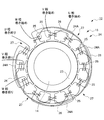
- FIG. 2 is a diagram showing a configuration of the magnet portion 23 of the rotor 14 and the stator core 24 of the stator 15.
- the magnet portion 23 of the rotor 14 is configured by eight magnetic poles.
- the stator 15 has a plurality (12) of teeth 25 formed so that the tip faces the rotor 14, and these teeth 25 are arranged radially and at regular angular intervals in the circumferential direction. Each coil is wound to form a magnetic pole.
- the stator core 24 is configured using a plurality of small cores 24A having a shape in which the outer peripheral sides of a predetermined number of teeth 25 are connected by a core back 26.
- the plurality of small cores 24A are arranged at regular intervals in the circumferential direction, and a portion (hereinafter referred to as a gap portion) 27 where the core back 26 does not exist between adjacent teeth 25 of the adjacent small cores 24A is provided.
- the stator core 24 of the annular stator 15 surrounding the rotor 14 is divided into small cores 24 ⁇ / b> A having a substantially arc shape (substantially fan shape) by the gap portion 27.
- the interval between the gap portions 27 is set so that the number of teeth 25 between adjacent gap portions 27 is M ⁇ n (n is an integer of 1 or more), where M is the number of phases of the electric motor 10. Is done.
- n is set to a value of 1
- the number of teeth 25 between adjacent gap portions 27 is set to three.
- the small core 24A is formed in a substantially arc shape (substantially fan shape) in which base portions of M ⁇ n teeth arranged radially at a constant angular interval are connected by a core back, and the four small cores 24A A stator core 24 is formed.
- Each small core 24A is manufactured by laminating electromagnetic steel sheets.
- the core back 26 between the teeth 25 in the small core 24A A magnetic closed circuit can be formed for each tooth of the small core 24A, thereby driving the rotor 14 in the same manner as in the case where the stator is formed by the annular core according to the conventional configuration described above with reference to FIG. be able to.
- the amount of the core material used can be reduced by the amount of the gap portion 27 as compared with the conventional case.
- the stator core 24 is manufactured by the four small cores 24A in this way, the number of the small cores 24A can be increased and the material used can be reduced. That is, for example, when a core is formed by stacking electromagnetic steel plates, as shown in FIG. 3, in the conventional annular shaped stator core 4, a rectangular region having a length H whose one side is longer than the diameter of the stator core 4. It is necessary to punch and laminate the electromagnetic steel sheet.
- eight small cores 24A can be produced from a rectangular region having a length H on one side. Can be increased to reduce the material associated with the core.
- the performance of the electric motor can be improved by effectively using the gap of the gap portion 27.
- the air gap of the gap portion 27 is set as a cooling gas flow path to improve the heat dissipation efficiency, thereby improving the performance.
- the radiating efficiency can be improved, thereby improving the performance.
- this gap can be used for the wiring space of the device in which the electric motor 10 is disposed and the space for arranging various members, thereby simplifying the configuration of the device.
- both end portions on the circumferential side of the small core 24A are formed so that the end portion of the core back 26 becomes the end portion of the tooth 25, and the core back 26 is formed with an arc shape on the outer peripheral side.
- the shape of the end portion and the shape of the outer peripheral side are appropriately modified according to the arrangement method and fixing method of the small core 24A described later.
- stator arrangement By the way, in the case of producing the stator core with the annular shape in FIG. 16 described above, the relative misalignment of the plurality of teeth can be sufficiently reduced by punching, and the stator core can be produced with high accuracy.
- the stator core 24 is produced by arranging the plurality of small cores 24A apart from each other by the gap portion 27 as in this embodiment, the production accuracy of the stator core 24 decreases, and as a result, the rotor 14 There is a risk that the magnetic poles of the stator 15 cannot be arranged close to each other.
- the positioning error between the small cores 24A is sufficiently reduced, and the accuracy of the stator core 24 is improved. I try to prevent the decline. Further, by effectively using the insulating member used for winding the coil, and holding the plurality of small cores 24A constituting the stator core 24 by the insulating member in the casing 11A, the stator core 24 is A reduction in the efficiency of the mounting work when the small core 24A is used is prevented.
- the coil 15 is wound around each tooth
- yen is arrange
- the coil can be wound by effectively utilizing the winding equipment applied to the stator core having the ring shape.
- FIG. 5 is a plan view (FIG. 5 (B)) showing a state where the stator 15 is arranged in the casing 11A, and a cross-sectional view (FIG. 5 (A)) taken along line AA.
- the insulator 28 is used as an insulating member for integrating the small cores 24A.
- the insulator 28 extends along the inner peripheral side of the core back 26 with the coil bobbin portion 29 provided for each tooth 25 of each small core 24A constituting the stator core 24 and the coil bobbin portion 29 of the tooth 25 in each small core 24A. It is formed in an annular shape by the connecting portion 30 that is connected in all shapes.
- the coil bobbin part 29 is comprised by the site
- the insulator 28 is a protective material for insulating the core and the magnet wire and preventing the magnet wire from being damaged during winding.
- a flame-retardant resin such as 66 nylon is injection-molded. Is produced.
- the insulator 28 includes an upper insulator 28A that covers each of the teeth 25 from above and a lower insulator 28B that covers each of the teeth 25 from below, and a small core is formed from both sides in the axial direction by the pair of insulators 28A and 28B.
- the four small cores 24A are integrated by sandwiching 24A.
- the coils 32 are wound around the teeth 25 to form the stator 15, and then incorporated into the casing 11A.
- both end portions of the core back 26 extend to the gap portion 27 side, and a through hole 33 is formed in the extended portion.
- the casing 11A is provided with a step 31 inside, and the stator 15 is positioned in the direction along the rotation axis by contacting the outer peripheral side portion of the core back 26 of each small core 24A with the step 31. .
- the casing 11 ⁇ / b> A is provided with a positioning hole 34 corresponding to the through-hole 33 at the level difference 31.
- the stator 15 can fix both ends of each small core 24 ⁇ / b> A in the circumferential direction to the case 11 by inserting the pin portion of the fixing pin 35 into the through hole 33 of the core back 26 and press-fitting into the positioning hole 34.
- the stator core 24 including the four small cores 24 ⁇ / b> A is supported by the case 11.
- the fixing pin 35 is formed in a U-shape, and the two pin portions of the fixing pin 35 are respectively inserted into the through holes 33 of the adjacent small cores 24A and press-fitted into the positioning holes. Adjacent ends of the core 24A are collectively fixed to the casing 11A to simplify the attaching operation of the stator 15.
- FIG. 6 is a diagram showing a manufacturing process of the stator 15 according to this embodiment.
- a small core 24A is produced by punching and laminating electromagnetic steel sheets (steps ST1-ST2).
- step ST3 After the four small cores 24A are integrated using the insulator 28 (step ST3), coils are wound around the teeth 25 of the small cores 24A to produce the stator 15 (steps ST4-ST5).
- the teeth 25 are arranged in an annular shape, so that the winding in the conventional annularly shaped stator core 4 (FIG. 16) is performed. It can be performed in the same manner as the process.
- the stator core 4 is divided into a plurality of small cores 24A as shown in FIG.
- the stator 15 can be configured by the windings.
- the amount of material used can be reduced with respect to the core.
- the material used can be reduced due to the increase in the number of parts.
- the plurality of small cores 24A with the insulating member, it is possible to prevent an increase in man-hours for winding work and the like.
- the mounting error of the plurality of small cores 24A can be sufficiently reduced.
- the insulating members are a pair of insulators 28A and 28B, and a plurality of small cores 24A are sandwiched and integrated from both sides in the axial direction by the pair of insulators 28A and 28B, thereby configuring the pair of insulators 28A and 28B.
- the small cores 24A can be integrated by effectively utilizing the above.
- each small core 24A can be accurately used by effectively utilizing the configuration of the case 11. Can be held.
- FIG. 7 shows an electric motor according to a second embodiment of the present invention.
- FIG. 7B is a plan view showing a state where the stator 45 is arranged on the casing 41A
- FIG. 7A is this plan view.
- FIG. 6 is a cross-sectional view taken along the line BB, and is used for explaining the stator 45 by comparison with FIG.
- This embodiment is configured in the same way as the first embodiment except that the configuration of the fixing means of each small core 44A applied to the stator 45 is different.
- the four small cores 44A constituting the stator core are provided with fan-shaped convex portions 46 on the back side of the core back 26.
- a recess 42 for press-fitting the protrusion 46 is formed corresponding to each small core 44A.
- the stator 45 is held by the first casing 41A by press-fitting the convex portions 46 of the small cores 44A into the concave portions 42 of the first casing 41A from the axial direction.
- each convex part 46 fits in each concave part 42 in a wedge shape, each small core 44A does not shift in the radial direction with respect to the first casing 41A.
- each small core 44A can be fixed by press-fitting to the first casing 41A, and each small core 24A can be accurately held using a case, which is the same as in the first embodiment. An effect can be obtained.
- FIG. 8 shows an electric motor according to a third embodiment of the present invention.
- FIG. 8B is a plan view showing a state in which the stator 55 is arranged in the casing 51A, and FIG. 8A is this plan view.
- FIG. 6 is a cross-sectional view taken along line CC, and is used for explaining the stator 55 in comparison with FIG.
- This embodiment is configured in the same way as the first embodiment except that the configuration of the fixing means of the small core 54A applied to the stator 55 is different.
- Through holes 53 are formed at both ends of the core back 26 in the four small cores 54A constituting the stator core.
- a screw hole 54 corresponding to the through hole 53 is provided at the position of the step 31.
- each small core 54A can be fixed to the first casing 51A with a screw 56, and each small core 54A can be accurately held using a case, as in the first embodiment. The effect of can be obtained.
- FIG. 9 shows an electric motor according to a fourth embodiment of the present invention.
- FIG. 9B is a plan view showing a state in which the stator 65 is arranged in the casing 61A, and FIG. 9A is this plan view.
- FIG. 6 is a cross-sectional view taken along line DD, and is used for explaining the stator 65 in comparison with FIG.
- This embodiment is configured in the same way as the first embodiment except that the configuration of the fixing means of the small core 64A applied to the stator 65 is different.
- narrow grooves 67 and 66 are formed at positions corresponding to both ends of the small core 64A and both ends of the small core 64A in the casing 61A so as to obliquely cross the boundary between the small core 64A and the casing 61A. Is done.
- the metal plate material 68 is press-fitted across the narrow grooves 67 and 66, the small core 64A is held in the case, and the stator core is held in the case.
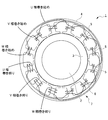
- FIG. 10 shows an electric motor according to a fifth embodiment of the present invention in comparison with FIG.
- the electric motor 70 according to this embodiment is configured in the same manner as the electric motor 10 of the first embodiment except that the configuration according to FIG. 10 and related configurations are different.
- the electric motor 70 is an outer rotor type three-phase brushless DC electric motor.
- a stator 75 is formed in a substantially cylindrical shape, and a rotor 74 is provided so as to surround the stator 75.
- the rotor 74 is provided with a magnet portion 73 having a large number of magnetic poles formed in the circumferential direction.
- a plurality of teeth 85 formed so that the tips thereof are opposed to the rotor 74 are arranged radially and at a constant angular interval in the circumferential direction, and a magnetic wire is wound around each of the teeth 85 to generate magnetic poles. It is formed.
- a predetermined number of adjacent teeth 85 are connected at their inner peripheral sides by a core back 86, and a magnetic closed circuit of the predetermined number of teeth 85 is formed.
- a predetermined number of teeth 85 are connected by a core back 86 to form a small core 84A.
- a plurality of such small cores 84A are arranged at regular intervals in the circumferential direction, and adjacent small cores 84A are mutually connected.
- a gap portion 87 where the core back 86 does not exist is provided between the adjacent teeth 85. That is, the stator 75 has a shape divided into small cores 84 ⁇ / b> A having a substantially arc shape (substantially fan shape) by the gap portion 87.
- the interval between the gap portions 87 is set so that the number of teeth 85 between the adjacent gap portions 87 is the number of phases M ⁇ n of the electric motor 70 (n is an integer of 1 or more). In this embodiment, n is set to a value of 1, and the number of teeth 85 between adjacent gap portions 87 is set to three.
- the stator 75 is fixed to the case by winding a coil after the small core 84A is integrated in the same manner as in the first to fourth embodiments. Even if this embodiment is applied to an outer rotor type electric motor, the same effects as those of the above-described embodiment can be obtained.
- FIG. 11 shows an electric motor according to a sixth embodiment of the present invention.
- FIG. 11 (B) is a plan view showing a state in which a stator 115 is arranged on a casing 111A
- FIG. 11 (A) is a plan view thereof.
- FIG. 6 is a cross-sectional view taken along line EE.
- 12A is an enlarged plan view showing the small core 124A in a state where the coil 132 is wound
- FIG. 12B is a cutaway view of FIG. 12A taken along line FF. It is sectional drawing.
- FIG. 12C is a plan view of the small core 124A.
- the insulator 128 is applied to an insulating member used for winding the coil 132.
- the insulator 128 is provided for each of the four small cores 124 ⁇ / b> A constituting the stator core 124, and the coil bobbin portion 129 that covers the three teeth 125 in the small core 124 ⁇ / b> A and the adjacent coil bobbin portion 129 are at least the inner periphery of the core back 126. It is formed by the connection part 130 connected by the shape along the side.
- the coil bobbin part 129 is comprised by the site
- the insulator 128 is a protective material for insulating the core and the magnet wire and further preventing the magnet wire from being damaged during winding.
- the insulator 128 is manufactured by injection molding a flame retardant resin such as 66 nylon. . 11 and 12, the insulator 128 includes an upper insulator 128A that covers each tooth 125 from above and a lower insulator 128B that covers each tooth 125 from below, and the pair of insulators 128A and 128B causes both sides in the axial direction.
- the small core 124A is sandwiched between and attached to the small core 124A.
- Each of the small cores 124A is disposed in the casing 111A after the coils 132 are wound around the teeth 125 via the coil bobbin portion 129, and the four small cores 124A are provided with gap portions 127 between the adjacent small cores 124A.
- the stator 115 is completed by being disposed in the casing 111A.
- both end portions of the core back 126 extend in a substantially rectangular shape in the outer peripheral direction, and a through hole 133 is formed in the extended portion.
- the casing 111A is provided with a step 131 on the inner side, and the step 131 abuts on the outer peripheral side portion of the core back 126 of the small core 124A, thereby positioning each small core 124A in the direction along the rotation axis.
- the casing 111 ⁇ / b> A is further provided with a screw hole at a position corresponding to the through hole 133.
- the small core 124A is supported by the case 111 by inserting screws 134 into the through holes 133 at both ends thereof and screwing them into the screw holes of the casing 111A.
- FIG. 13 is a diagram showing a manufacturing process of the stator 115 according to this embodiment.
- the small core 124A is manufactured by punching and laminating electromagnetic steel as described above (steps ST11 to ST12).
- the insulator 128 is disposed on the small core 124A (step ST13).
- a magnet wire is wound around each of the teeth 125 insulated by the insulator 128 (step ST14), whereby the coil 132 is wound around the small core 124A.
- each small core 124A is fixed to the case, and each small core 124A constituting the stator 115 is arranged in an annular shape and integrated. Further, a coil is connected for each phase, thereby producing a stator 115 (step ST15).
- the gap portion 127 where the core back is not provided between the adjacent teeth 125 it is possible to reduce the amount of material used for the core, and further, As a result of the increase, the material used can be reduced. Further, by providing an insulating member on each of the small cores 124A and winding the coils 132 so that the small cores 124A are integrally held by the case, an increase in work man-hours can be prevented, and moreover, The mounting error of the small core 124A can be sufficiently reduced depending on the case.
- stator 115 can be reliably held in the case with a simple configuration.
- FIG. 14 shows an electric motor according to a seventh embodiment of the present invention.
- FIG. 14 (B) is a plan view showing a state where the stator 145 is arranged on the casing 141A
- FIG. 14 (A) is this plan view.
- FIG. 6 is a cross-sectional view taken along line GG, and is used for explaining the stator 145 by comparison with FIG.
- This embodiment is configured in the same manner as the sixth embodiment except that the configuration of the fixing means of the small core 144A applied to the stator 145 is different.
- the small core 144A is provided with a fan-shaped convex portion 146 on the back side of the core back 126.
- the first casing 141A is formed with a concave portion 142 into which the convex portion 146 fits.
- the small core 144A is held by the first casing 141A by press-fitting the convex portion 146 into the concave portion 142 of the first casing 141A from the axial direction.
- a gap portion 127 is formed between the small cores 144A to form the stator 145, which is attached to the case.
- each small core 144A can be fixed to the first casing 141A by press-fitting, and the same effect as the above-described embodiment can be obtained.
- FIG. 15 is a diagram showing a small core 154A applied to the electric motor according to the eighth embodiment of the present invention.
- the small core 154A is formed by laminating a plurality of core sheets 151 produced by punching out electromagnetic steel sheets by pressing. During the lamination, the core sheets 151 are laminated so as to be displaced in the circumferential direction sequentially by a certain angle. As a result, in this embodiment, the small core 154A is formed so that the core sheet 151 gradually displaces in the circumferential direction including the portion of the tooth 125 that faces the rotor 114, thereby applying a skew.
- This embodiment is configured in the same manner as the sixth or seventh embodiment except that the skew is applied.
- the small core 154A is inclined so that the slots between the teeth 125 are oriented in the vertical direction.
- each can be wound through a magnet wire in a rectangular shape.
- the winding apparatus conventionally used.
- the insulator is omitted for the sake of explanation, but actually, the coil is wound after the insulator is mounted on the skewed small core 154A.
- a molding resin can be applied to the small core insulating member, and a plurality of small cores can be integrated by an insert mold using the molding resin.
- the same effect as the above-mentioned embodiment can be acquired by integrating a small core with the insert mold which uses mold resin.
- N may be set to a value of 2 to set the number of teeth between the gap portions to six.
- the number of teeth between the gap portions may be four or five larger than three, or may be a number other than the number of phases ⁇ n.
- the present invention is not limited to this, and motors having various numbers of phases such as two-phase, and various slots. It can be widely applied to electric motors.
- the present invention is not limited to the application to a brushless DC motor, but can be widely applied to various motors such as an inner rotor brush DC motor, an inner rotor AC motor, and an outer rotor AC motor.
- the present invention is not limited to this and can be widely applied to an inner rotor type and an outer rotor type generator.
- the rotating electrical machine according to the present invention can reduce the material used and reduce the cost as compared with the conventional one, and can be applied to various motors and generators of the inner rotor type and the outer rotor type.
Abstract
An M-phase rotating electric machine (10) is formed by housing a rotor (14) and a stator (15) in a case (11), said stator being formed by winding a coil around each of a plurality of teeth (25) disposed in a radial fashion. In the rotating electric machine, the stator has a plurality of small cores (24A) each equipped with a predetermined number of teeth and a core back (26) for coupling the base portions of these teeth and disposed in a circumferential direction at constant angle intervals and is provided with gap regions (27) between adjacent small cores. The small cores are integrated by a ring-shaped insulating member (28) that couples the coil bobbin portions (29) of the teeth through a connection portion (30). Alternatively, the small cores are integrated in such a way that the insulating member is provided that couples the coil bobbin portions of the teeth through the connection portion, the coil is wound around each of the teeth, and then the core back is fixed to the case by a fixing means (33, 34, 35).
Description
本発明は、インナーロータ型、アウターロータ型による各種電動機、発電機(以下、電動機及び発電機を総称して回転電機と呼ぶ)に関する。
The present invention relates to various types of electric motors and generators using an inner rotor type and an outer rotor type (hereinafter, the electric motor and the generator are collectively referred to as a rotating electric machine).
従来、インナーロータ型のブラシレス直流電動機は、略円筒形状のステータの内側に、円柱形状のロータをステータに対して同心状に配置して形成される。ステータは、内周側に突出する複数のティースの基部を円筒形状のコアバックにより連結することによりステータコアが作製され、各ティースにはコイルが巻装される。
Conventionally, an inner rotor type brushless DC motor is formed by arranging a columnar rotor concentrically with respect to a stator inside a substantially cylindrical stator. A stator core is produced by connecting the bases of a plurality of teeth protruding on the inner peripheral side with a cylindrical core back, and a coil is wound around each tooth.
すなわち、図16は、従来のインナーロータ型のブラシレス直流電動機におけるロータとステータとを示す平面図である。電動機1において、ロータ2は、例えば異なる磁極が周方向に交互に配列されるよう着磁された円環状の磁石3を配置して構成され、中心に回転軸が設けられる。ステータコア4は、このロータ2を囲むように配置され、内側に突出する複数のティース5にそれぞれコイル6を巻装してステータ7が構成される。なお、図16は3相12スロットの例であり、ロータ2が8極の例である。
That is, FIG. 16 is a plan view showing a rotor and a stator in a conventional inner rotor type brushless DC motor. In the electric motor 1, the rotor 2 is configured by arranging, for example, an annular magnet 3 magnetized so that different magnetic poles are alternately arranged in the circumferential direction, and a rotating shaft is provided at the center. The stator core 4 is disposed so as to surround the rotor 2, and a stator 7 is configured by winding coils 6 around a plurality of teeth 5 protruding inward. FIG. 16 shows an example of 3 phases and 12 slots, and the rotor 2 has 8 poles.
このような電動機に関して、特許文献1には、複数の分割コアにコイルを巻き線した後、これら分割コアを一体化してステータを作製する方法が提案されている。また特許文献2及び特許文献3には、複数の固定子体によりロータを駆動する構成が開示されている。
Regarding such an electric motor, Patent Document 1 proposes a method in which a coil is wound around a plurality of divided cores, and then these divided cores are integrated to produce a stator. Patent Documents 2 and 3 disclose a configuration in which the rotor is driven by a plurality of stator bodies.
ところで、回転電機では、使用材料を低減することが望まれている。
Incidentally, in rotating electrical machines, it is desired to reduce the materials used.
本発明は以上の点を考慮してなされたものであり、回転電機に関して、従来に比して使用材料を低減することを目的とする。
The present invention has been made in consideration of the above points, and an object of the present invention is to reduce the materials used in a rotating electrical machine as compared with the related art.
本発明者は、上記課題を解決するために鋭意研究を重ね、隣接するティース間でコアバックが設けられていない部位をギャップ部位として、このギャップ部位を複数個所に設けるとの着想に至り、本発明を完成するに至った。またこのようにして作成される小コアを絶縁部材により一体化して、或いは、小コアにそれぞれ絶縁部材を設けるようにして、各小コアのケースへの固定によりステータをケースに組み込むとの着想に至り、本発明を完成するに至った。
The present inventor has intensively studied to solve the above-mentioned problems, and has led to the idea of providing a plurality of gap portions as a gap portion where a core back is not provided between adjacent teeth. The invention has been completed. The idea is to incorporate the stator into the case by integrating the small cores thus created with an insulating member, or by providing each small core with an insulating member, and fixing each small core to the case. As a result, the present invention has been completed.
(1) 本発明による回転電機の一つは、
ケースにロータ及びステータを収納して形成され、放射状に配置された複数のティースにそれぞれコイルを巻装して前記ステータが形成されてなる回転電機において、
前記ステータは、所定数の前記ティースと前記所定数のティースの基部を連結するコアバックとをそれぞれ備えた複数の小コアを、円周方向に一定の角度間隔で配置すると共に、隣接する小コアの間にそれぞれギャップ部位を設けることにより構成され、
前記複数の小コアは、前記複数の小コアのそれぞれの前記ティースに係るコイルボビン部を接続部により連結した環状の絶縁部材により一体化されて、固定手段により前記各コアバックが前記ケースに固定されている。 (1) One of the rotating electrical machines according to the present invention is:
In a rotating electrical machine in which a rotor and a stator are housed in a case, and the stator is formed by winding coils around a plurality of radially arranged teeth.
The stator includes a plurality of small cores each having a predetermined number of teeth and a core back that connects the bases of the predetermined number of teeth, and the adjacent small cores are arranged at regular angular intervals in the circumferential direction. Each is provided by providing a gap portion,
The plurality of small cores are integrated by an annular insulating member in which a coil bobbin portion related to the teeth of each of the plurality of small cores is connected by a connecting portion, and each core back is fixed to the case by a fixing means. ing.
(1)の回転電機によれば、電動機に関して、ギャップ部位を設けた分、コアに係る材料を低減することができる。また絶縁部材により複数の小コアを一体化してケースに組み込むことにより、作業工数の増大を防止することができる。さらにコアバックをケースに固定して小コアをケースに収納することにより、複数の小コアの取り付け誤差をケースにより充分に小さくすることができる。
According to the rotating electrical machine of (1), the material related to the core can be reduced by the amount of the gap portion provided for the electric motor. Further, by integrating a plurality of small cores with the insulating member and incorporating them into the case, an increase in work man-hours can be prevented. Further, by fixing the core back to the case and storing the small core in the case, it is possible to sufficiently reduce the mounting error of the plurality of small cores.
(2) 本発明による回転電機の製造方法の一つは、
電磁鋼板の積層により、放射状に配置された所定数のティースの基部をコアバックで接続した形状による小コアを作成する小コア作成工程と、
複数の前記小コアを、各ティースに係るコイルボビン部を接続部により連結した環状の絶縁部材により一体化してステータコアを作成する一体化の工程と、
前記ステータコアの前記ティースに前記コイルボビン部を介しコイルを巻装してステータを作製する巻き線工程と、
前記ステータ及びロータをケースに組み込む組込工程とを備え、
前記組込工程は、
前記小コアのコアバックを、固定手段により前記ケースに固定して前記ステータを前記ケースに組み込む。 (2) One of the methods for manufacturing a rotating electrical machine according to the present invention is:
A small core creation step of creating a small core with a shape in which base portions of a predetermined number of teeth arranged radially are connected by a core back by lamination of electromagnetic steel sheets;
An integration step of creating a stator core by integrating a plurality of the small cores with an annular insulating member in which coil bobbin portions related to each tooth are connected by a connection portion;
A winding step of winding a coil on the teeth of the stator core via the coil bobbin portion to produce a stator;
An assembly step of incorporating the stator and the rotor into a case,
The incorporation step is
The core back of the small core is fixed to the case by a fixing means, and the stator is incorporated into the case.
(2)の回転電機の製造方法によれば、ギャップ部分によりコアの使用量を低減してなる回転電機の製造方法に関して、絶縁部材により複数の小コアを一体化して組み込むことにより、作業工数の増大を防止することができる。またコアバックをケースに固定して小コアをケースに収納することにより、複数の小コアの取り付け誤差をケースにより充分に小さくすることができる。
According to the method for manufacturing a rotating electrical machine of (2), with respect to the method for manufacturing a rotating electrical machine in which the amount of use of the core is reduced by the gap portion, by integrating a plurality of small cores with an insulating member, An increase can be prevented. Further, by fixing the core back to the case and storing the small core in the case, it is possible to sufficiently reduce the mounting error of the plurality of small cores.
(3) 本発明の回転電機の他の一つは、
ケースにロータ及びステータを収納して形成され、放射状に配置された複数のティースにそれぞれコイルを巻装して前記ステータが形成されてなる回転電機において、
前記ステータは、所定数の前記ティースと前記所定数のティースの基部を連結するコアバックとをそれぞれ備えた複数の小コアを、円周方向に、一定の角度間隔で配置すると共に、隣接する小コアの間にそれぞれギャップ部位を設けることにより構成され、
前記複数の小コアには、各ティースに係るコイルボビン部とこれらコイルボビン部を連結した接続部とにより構成した絶縁部材が設けられ、各ティースに前記コイルボビン部を介して前記コイルが巻装され、
前記複数の小コアは、それぞれのコアバックが固定手段により前記ケースに固定されて、前記ケースにより一体化される。 (3) Another one of the rotating electrical machines of the present invention is
In a rotating electrical machine in which a rotor and a stator are housed in a case, and the stator is formed by winding coils around a plurality of radially arranged teeth.
In the stator, a plurality of small cores each including a predetermined number of teeth and a core back that connects the bases of the predetermined number of teeth are arranged in the circumferential direction at constant angular intervals, and adjacent small cores are arranged. It is configured by providing gap portions between the cores,
The plurality of small cores are provided with an insulating member constituted by a coil bobbin portion related to each tooth and a connection portion connecting these coil bobbin portions, and the coil is wound around each tooth via the coil bobbin portion,
The plurality of small cores are integrated with each other by fixing the respective core backs to the case by fixing means.
(3)の回転電機によれば、ギャップ部位を設けた分、コアに係る材料を低減することができる。また各小コアに絶縁部材、コイルを設けた後、ケースに固定して一体化することにより、複数の小コアの取り付け誤差をケースにより充分に小さくすることができる。
According to the rotating electrical machine of (3), the material related to the core can be reduced by the amount of the gap portion. Moreover, after providing an insulating member and a coil in each small core, and fixing to a case and integrating, the attachment error of a some small core can be made small enough by a case.
(4) 本発明の回転電機の製造方法の他の一つは、
電磁鋼板の積層により、放射状に配置された所定数のティースの基部をコアバックで接続した形状による小コアを作成する小コア作成工程と、
前記小コア毎に絶縁部材を配置して各ティースにコイルを巻装する巻き線工程と、
前記コイルを巻装した複数の小コア、及びロータをケースに組み込む組込工程とを備え、
前記組込工程は、
前記小コアのコアバックを、固定手段により前記ケースに固定して、前記複数の小コアをそれぞれギャップ部位を介して円周方向に順次配置して前記複数の小コアを一体化することにより、前記ステータを前記ケースに組み込む。 (4) Another method for manufacturing a rotating electrical machine of the present invention is as follows:
A small core creation step of creating a small core with a shape in which base portions of a predetermined number of teeth arranged radially are connected by a core back by lamination of electromagnetic steel sheets;
A winding step of arranging an insulating member for each small core and winding a coil around each tooth;
A plurality of small cores wound with the coil, and an assembling step of incorporating the rotor into the case,
The incorporation step is
The core back of the small core is fixed to the case by a fixing means, and the plurality of small cores are sequentially arranged in the circumferential direction through gap portions, respectively, and the plurality of small cores are integrated. The stator is incorporated in the case.
(4)の回転電機の製造方法によれば、ギャップ部位を設けた分、コアに係る材料を低減することができる。また各小コアに絶縁部材、コイルを設けた後、ケースに固定して一体化することにより、複数の小コアの取り付け誤差をケースにより充分に小さくすることができる。
According to the method for manufacturing a rotating electrical machine of (4), the material related to the core can be reduced by the amount of the gap portion. Moreover, after providing an insulating member and a coil in each small core, and fixing to a case and integrating, the attachment error of a some small core can be made small enough by a case.
本発明によれば、コアに関して、使用材料量を低減することができ、さらには取り数の増大によっても、使用材料を低減することができる。また作業工数の増大を防止することができ、さらには複数の小コアの取り付け誤差を充分に小さくすることがでる。
According to the present invention, it is possible to reduce the amount of material used for the core, and it is also possible to reduce the material used by increasing the number of cores. In addition, an increase in the number of work steps can be prevented, and furthermore, attachment errors of a plurality of small cores can be sufficiently reduced.
以下、本発明の実施形態につき図面を参照して説明する。なお以下の説明において、モータの中心軸方向における上側を単に「上側」と呼び、下側を単に「下側」と呼ぶ。この上下方向は、実際の機器に組み込まれたときの位置関係や方向を示すものではない。また、中心軸に平行な方向を「軸方向」と呼び、中心軸を中心とする径方向を単に「径方向」と呼び、中心軸を中心とする周方向を単に「周方向」と呼ぶ。
Hereinafter, embodiments of the present invention will be described with reference to the drawings. In the following description, the upper side in the central axis direction of the motor is simply referred to as “upper side”, and the lower side is simply referred to as “lower side”. This vertical direction does not indicate the positional relationship or direction when incorporated in an actual device. A direction parallel to the central axis is referred to as an “axial direction”, a radial direction centered on the central axis is simply referred to as “radial direction”, and a circumferential direction centered on the central axis is simply referred to as “circumferential direction”.
〔第1実施形態〕
図1は、本発明の第1実施形態に係る電動機を示す断面図である。この電動機10は、インナーロータ型の3相ブラシレス直流電動機であり、例えばアルミダイカストにより第1ケーシング11A及び第2ケーシング11Bがカップ形状に形成され、これら第1ケーシング11A及び第2ケーシング11Bが互いの開口部を対向させた状態で結合されて略円柱形状にケース11が形成される。電動機10は、このケース11にロータ14、ステータ15等を収納して構成される。 [First Embodiment]
FIG. 1 is a cross-sectional view showing an electric motor according to a first embodiment of the present invention. Theelectric motor 10 is an inner rotor type three-phase brushless DC electric motor. For example, the first casing 11A and the second casing 11B are formed in a cup shape by aluminum die casting, and the first casing 11A and the second casing 11B are mutually connected. The case 11 is formed in a substantially cylindrical shape by being coupled with the openings facing each other. The electric motor 10 is configured by housing a rotor 14, a stator 15, and the like in the case 11.
図1は、本発明の第1実施形態に係る電動機を示す断面図である。この電動機10は、インナーロータ型の3相ブラシレス直流電動機であり、例えばアルミダイカストにより第1ケーシング11A及び第2ケーシング11Bがカップ形状に形成され、これら第1ケーシング11A及び第2ケーシング11Bが互いの開口部を対向させた状態で結合されて略円柱形状にケース11が形成される。電動機10は、このケース11にロータ14、ステータ15等を収納して構成される。 [First Embodiment]
FIG. 1 is a cross-sectional view showing an electric motor according to a first embodiment of the present invention. The
ロータ14は、その回転軸13が第1ケーシング11A及び第2ケーシング11Bにそれぞれ保持されたボールベアリング12A及び12Bにより回転自在に支持される。このロータ14を外周方向より囲むように、ロータ14に対して同心状にステータ15が設けられ、このステータ15におけるコイルを励磁する駆動回路を実装した配線基板16がステータ15のボールベアリング12B側に配置される。この配線基板16には、ホール素子等によるロータ14の回転位置検出機構が設けられ、電動機10は、この回転位置検出機構による回転位置検出結果に基づいて、配線基板16に設けられた駆動回路によりコイルの励磁状態を制御し、これによりロータ14を回転させる。
The rotor 14 is rotatably supported by ball bearings 12A and 12B whose rotation shaft 13 is held by the first casing 11A and the second casing 11B, respectively. A stator 15 is provided concentrically with the rotor 14 so as to surround the rotor 14 from the outer peripheral direction, and a wiring board 16 on which a drive circuit for exciting a coil in the stator 15 is mounted is disposed on the ball bearing 12B side of the stator 15. Be placed. The wiring board 16 is provided with a rotational position detection mechanism of the rotor 14 using a hall element or the like. The excitation state of the coil is controlled, and thereby the rotor 14 is rotated.
ここで、ロータ14は、例えばフェライトプラスチックマグネットによるロータマグネット14Aに回転軸13を圧入して形成される。ロータマグネット14Aには、ステータ15に対向する外周側部位が形成され、着磁によりこの外周側部位に周方向に複数の磁極を形成した磁石部23が設けられ、この磁石部23がステータ15に対向する。
Here, the rotor 14 is formed by press-fitting the rotary shaft 13 into a rotor magnet 14A made of, for example, a ferrite plastic magnet. The rotor magnet 14 </ b> A has an outer peripheral portion facing the stator 15, and is provided with a magnet portion 23 in which a plurality of magnetic poles are formed circumferentially on the outer peripheral portion by magnetization, and the magnet portion 23 is provided on the stator 15. opposite.
図2は、ロータ14の磁石部23と、ステータ15のステータコア24との構成を示す図である。この実施形態において、ロータ14の磁石部23が8極の磁極により構成される。ステータ15は、先端がロータ14と対向するように形成された複数(12個)のティース25を有し、これらティース25が放射状でかつ周方向に一定の角度間隔で配置され、各ティース25にそれぞれコイルが巻装されて磁極が形成される。
FIG. 2 is a diagram showing a configuration of the magnet portion 23 of the rotor 14 and the stator core 24 of the stator 15. In this embodiment, the magnet portion 23 of the rotor 14 is configured by eight magnetic poles. The stator 15 has a plurality (12) of teeth 25 formed so that the tip faces the rotor 14, and these teeth 25 are arranged radially and at regular angular intervals in the circumferential direction. Each coil is wound to form a magnetic pole.
この実施形態において、ステータコア24は、所定数のティース25の外周側をコアバック26により接続した形状の複数個の小コア24Aを用いて構成される。複数個の小コア24Aは、円周方向に一定の間隔で配列され、隣接する小コア24Aの隣り合うティース25間にコアバック26が存在しない部位(以下、ギャップ部位と呼ぶ)27が設けられる。換言すれば、ロータ14を囲む円環形状のステータ15のステータコア24が、このギャップ部位27により、略円弧形状(略扇形状)による小コア24Aに分割された形となる。
In this embodiment, the stator core 24 is configured using a plurality of small cores 24A having a shape in which the outer peripheral sides of a predetermined number of teeth 25 are connected by a core back 26. The plurality of small cores 24A are arranged at regular intervals in the circumferential direction, and a portion (hereinafter referred to as a gap portion) 27 where the core back 26 does not exist between adjacent teeth 25 of the adjacent small cores 24A is provided. . In other words, the stator core 24 of the annular stator 15 surrounding the rotor 14 is divided into small cores 24 </ b> A having a substantially arc shape (substantially fan shape) by the gap portion 27.
ここで、ギャップ部位27間の間隔は、電動機10の相数をMとした場合、隣接するギャップ部位27間におけるティース25の数がM×n(nは1以上の整数)であるように設定される。この実施形態では、nが値1に設定されて、隣接するギャップ部位27間におけるティース25の数が3個に設定される。これにより、小コア24Aは、一定の角度間隔により放射状に配置されたM×n個のティースの基部をコアバックにより接続した略円弧形状(略扇形状)により形成され、4つの小コア24Aによりステータコア24が形成される。なお各小コア24Aは、電磁鋼板の積層により作製される。
Here, the interval between the gap portions 27 is set so that the number of teeth 25 between adjacent gap portions 27 is M × n (n is an integer of 1 or more), where M is the number of phases of the electric motor 10. Is done. In this embodiment, n is set to a value of 1, and the number of teeth 25 between adjacent gap portions 27 is set to three. As a result, the small core 24A is formed in a substantially arc shape (substantially fan shape) in which base portions of M × n teeth arranged radially at a constant angular interval are connected by a core back, and the four small cores 24A A stator core 24 is formed. Each small core 24A is manufactured by laminating electromagnetic steel sheets.
このように、ギャップ部位27を設ける場合にあって、隣接するギャップ部位27間におけるティース25の数がM×nであるように設定すれば、小コア24Aにおけるティース25間のコアバック26により、小コア24Aの各ティースについて磁気的な閉回路を構成することができ、これにより図16について上述した従来構成に係る円環形状のコアによりステータを構成する場合と同様に、ロータ14を駆動することができる。
As described above, when the gap portion 27 is provided and the number of the teeth 25 between the adjacent gap portions 27 is set to be M × n, the core back 26 between the teeth 25 in the small core 24A A magnetic closed circuit can be formed for each tooth of the small core 24A, thereby driving the rotor 14 in the same manner as in the case where the stator is formed by the annular core according to the conventional configuration described above with reference to FIG. be able to.
そうしてギャップ部位27を設けたことにより、このギャップ部位27の分、従来に比較してコア材の使用量を低減することができる。またこのように4つの小コア24Aによりステータコア24が作製されることにより、この小コア24Aの取り数が増大することによっても、使用材料を低減することができる。すなわち例えば電磁鋼板の積層によりコアを構成する際、図3に示すように、従来形状による円環形状のステータコア4では、ステータコア4の直径より1辺の長さが長い長さHによる矩形の領域より電磁鋼板を打ち抜いて積層することが必要になる。これに対して図3との対比により図4に示すように、この実施形態では、1辺が長さHの矩形の領域より、小コア24Aを8個作製することができ、これにより取り数を増大してコアに係る材料を低減することができる。
Thus, by providing the gap portion 27, the amount of the core material used can be reduced by the amount of the gap portion 27 as compared with the conventional case. In addition, since the stator core 24 is manufactured by the four small cores 24A in this way, the number of the small cores 24A can be increased and the material used can be reduced. That is, for example, when a core is formed by stacking electromagnetic steel plates, as shown in FIG. 3, in the conventional annular shaped stator core 4, a rectangular region having a length H whose one side is longer than the diameter of the stator core 4. It is necessary to punch and laminate the electromagnetic steel sheet. On the other hand, as shown in FIG. 4 in comparison with FIG. 3, in this embodiment, eight small cores 24A can be produced from a rectangular region having a length H on one side. Can be increased to reduce the material associated with the core.
このようにして作製されるステータコア24においては、ギャップ部位27の空隙を有効に利用して電動機の性能を向上することができる。例えば、ギャップ部位27の空隙を冷却用の気体の流路に設定して放熱効率を向上し、これにより性能を向上することができる。またこの空隙に、放熱フィンに熱的に結合した金属片、ヒートパイプ等を設けることによっても、放熱効率を向上し、これにより性能を向上することができる。さらにこの空隙を、電動機10が配置される装置の配線スペース、各種部材の配置スペースに利用して、当該装置の構成を簡略化することができる。
In the stator core 24 manufactured in this way, the performance of the electric motor can be improved by effectively using the gap of the gap portion 27. For example, the air gap of the gap portion 27 is set as a cooling gas flow path to improve the heat dissipation efficiency, thereby improving the performance. Further, by providing a metal piece, a heat pipe, or the like that is thermally coupled to the radiating fins in the gap, the radiating efficiency can be improved, thereby improving the performance. Furthermore, this gap can be used for the wiring space of the device in which the electric motor 10 is disposed and the space for arranging various members, thereby simplifying the configuration of the device.
なお、図2及び図4において、小コア24Aの円周側両端部は、コアバック26の端部がティース25の端部となるよう形成され、またコアバック26は、外周側が円弧形状により作成され、図では簡略化して示されているが、これら端部の形状、外周側の形状は、後述する小コア24Aの配置方法や固定方法に応じて、適宜、変形した形状が採用される。
2 and 4, both end portions on the circumferential side of the small core 24A are formed so that the end portion of the core back 26 becomes the end portion of the tooth 25, and the core back 26 is formed with an arc shape on the outer peripheral side. Although simplified in the drawing, the shape of the end portion and the shape of the outer peripheral side are appropriately modified according to the arrangement method and fixing method of the small core 24A described later.
〔ステータの配置〕
ところで、前記した図16について、円環形状によりステータコアを作成する場合は、打ち抜きにより、複数のティースの相対的な位置ずれを充分に小さくして、高い精度によりステータコアを作成することができる。しかしながらこの実施形態のように、ギャップ部位27の分だけ複数の小コア24Aを離間した状態で配置してステータコア24を作成する場合は、ステータコア24の作製精度が低下し、その結果、ロータ14に近接してステータ15の磁極を配置できなくなる恐れがある。 [Stator arrangement]
By the way, in the case of producing the stator core with the annular shape in FIG. 16 described above, the relative misalignment of the plurality of teeth can be sufficiently reduced by punching, and the stator core can be produced with high accuracy. However, when thestator core 24 is produced by arranging the plurality of small cores 24A apart from each other by the gap portion 27 as in this embodiment, the production accuracy of the stator core 24 decreases, and as a result, the rotor 14 There is a risk that the magnetic poles of the stator 15 cannot be arranged close to each other.
ところで、前記した図16について、円環形状によりステータコアを作成する場合は、打ち抜きにより、複数のティースの相対的な位置ずれを充分に小さくして、高い精度によりステータコアを作成することができる。しかしながらこの実施形態のように、ギャップ部位27の分だけ複数の小コア24Aを離間した状態で配置してステータコア24を作成する場合は、ステータコア24の作製精度が低下し、その結果、ロータ14に近接してステータ15の磁極を配置できなくなる恐れがある。 [Stator arrangement]
By the way, in the case of producing the stator core with the annular shape in FIG. 16 described above, the relative misalignment of the plurality of teeth can be sufficiently reduced by punching, and the stator core can be produced with high accuracy. However, when the
そこで、この実施形態では、ケース11を構成するケーシング11Aにステータコア24を構成する複数の小コア24Aを保持することにより、各小コア24A間の位置決め誤差を充分に低減し、ステータコア24の精度の低下を防止するようにしている。またコイルの巻装に使用する絶縁部材を有効に利用して、この絶縁部材によりステータコア24を構成する複数の小コア24Aを一体化した状態でケーシング11Aに保持することにより、ステータコア24を4つの小コア24Aにより構成する場合における取り付け作業の効率低下を防止している。また、絶縁部材を用いて各小コア24Aを一体化した状態において、各ティース25にコイルを巻装してステータ15を作成し、その後、ステータ15をケーシング11Aに配置することにより、従来の円環形状によるステータコアに適用していた巻線設備を有効に利用してコイルを巻装することができる。
Therefore, in this embodiment, by holding the plurality of small cores 24A constituting the stator core 24 in the casing 11A constituting the case 11, the positioning error between the small cores 24A is sufficiently reduced, and the accuracy of the stator core 24 is improved. I try to prevent the decline. Further, by effectively using the insulating member used for winding the coil, and holding the plurality of small cores 24A constituting the stator core 24 by the insulating member in the casing 11A, the stator core 24 is A reduction in the efficiency of the mounting work when the small core 24A is used is prevented. Moreover, in the state which integrated each small core 24A using the insulation member, the coil 15 is wound around each tooth | gear 25, the stator 15 is created, and the stator 15 is arrange | positioned to casing 11A after that, The conventional circle | round | yen is arrange | positioned. The coil can be wound by effectively utilizing the winding equipment applied to the stator core having the ring shape.
図5は、ケーシング11Aにステータ15を配置した状態を示す平面図(図5(B))、この平面図をA-A線により切り取って示す断面図(図5(A))である。この実施形態では、各小コア24Aを一体化する絶縁部材としてインシュレータ28が用いられる。ここでインシュレータ28は、ステータコア24を構成する各小コア24Aの各ティース25毎に設けられたコイルボビン部29と、各小コア24Aにおけるティース25のコイルボビン部29をコアバック26の内周側に沿った形状により全て接続する接続部30とにより円環形状に形成される。なお、コイルボビン部29は、ティース25を覆う部位とつばの部位とにより構成される。
FIG. 5 is a plan view (FIG. 5 (B)) showing a state where the stator 15 is arranged in the casing 11A, and a cross-sectional view (FIG. 5 (A)) taken along line AA. In this embodiment, the insulator 28 is used as an insulating member for integrating the small cores 24A. Here, the insulator 28 extends along the inner peripheral side of the core back 26 with the coil bobbin portion 29 provided for each tooth 25 of each small core 24A constituting the stator core 24 and the coil bobbin portion 29 of the tooth 25 in each small core 24A. It is formed in an annular shape by the connecting portion 30 that is connected in all shapes. In addition, the coil bobbin part 29 is comprised by the site | part which covers the teeth 25, and the collar part.
ここでインシュレータ28は、コアとマグネットワイヤとの間を絶縁し、さらには巻き線時のマグネットワイヤの傷つきを防止するための保護材であり、例えば66ナイロン等の難燃グレードの樹脂を射出成型して作製される。インシュレータ28は、図5を参照して上方より各ティース25を覆う上側インシュレータ28Aと下方より各ティース25を覆う下側インシュレータ28Bとからなり、これら一対のインシュレータ28A及び28Bにより軸方向両側から小コア24Aを挟持して4つの小コア24Aを一体化する。
Here, the insulator 28 is a protective material for insulating the core and the magnet wire and preventing the magnet wire from being damaged during winding. For example, a flame-retardant resin such as 66 nylon is injection-molded. Is produced. The insulator 28 includes an upper insulator 28A that covers each of the teeth 25 from above and a lower insulator 28B that covers each of the teeth 25 from below, and a small core is formed from both sides in the axial direction by the pair of insulators 28A and 28B. The four small cores 24A are integrated by sandwiching 24A.
4つの小コア24Aをインシュレータ28で一体化した後、各ティース25にコイル32が巻装されてステータ15が形成され、その後、ケーシング11Aに組み込まれる。ここで各小コア24Aは、コアバック26の両端部が、ギャップ部位27側に延出し、この延出した部位に貫通孔33が形成されている。ケーシング11Aには、内側に段差31が設けられており、この段差31に各小コア24Aのコアバック26における外周側部位が当接することにより、回転軸に沿った方向にステータ15が位置決めされる。ケーシング11Aには、この段差31の部位に、貫通孔33に対応する位置決め孔34が設けられる。ステータ15は、コアバック26の貫通孔33に固定ピン35のピン部を挿入して位置決め孔34に圧入することにより、各小コア24Aの円周方向の両端をそれぞれケース11に固定することができ、これにより4つの小コア24Aからなるステータコア24がケース11に支持される。
After integrating the four small cores 24A with the insulator 28, the coils 32 are wound around the teeth 25 to form the stator 15, and then incorporated into the casing 11A. Here, in each small core 24A, both end portions of the core back 26 extend to the gap portion 27 side, and a through hole 33 is formed in the extended portion. The casing 11A is provided with a step 31 inside, and the stator 15 is positioned in the direction along the rotation axis by contacting the outer peripheral side portion of the core back 26 of each small core 24A with the step 31. . The casing 11 </ b> A is provided with a positioning hole 34 corresponding to the through-hole 33 at the level difference 31. The stator 15 can fix both ends of each small core 24 </ b> A in the circumferential direction to the case 11 by inserting the pin portion of the fixing pin 35 into the through hole 33 of the core back 26 and press-fitting into the positioning hole 34. Thus, the stator core 24 including the four small cores 24 </ b> A is supported by the case 11.
この実施形態において、固定ピン35はコの字形状により形成され、固定ピン35の2つのピン部を隣接する小コア24Aの貫通孔33にそれぞれ挿入して位置決め孔に圧入することにより、各小コア24Aの隣接する端部を纏めてケーシング11Aに固定し、ステータ15の取り付け作業を簡略化している。
In this embodiment, the fixing pin 35 is formed in a U-shape, and the two pin portions of the fixing pin 35 are respectively inserted into the through holes 33 of the adjacent small cores 24A and press-fitted into the positioning holes. Adjacent ends of the core 24A are collectively fixed to the casing 11A to simplify the attaching operation of the stator 15.
図6は、この実施形態に係るステータ15の製造工程を示す図である。この製造工程では、まず、電磁鋼板を打ち抜いて積層することにより小コア24Aを作製する(ステップST1-ST2)。続いてインシュレータ28を使用して4つの小コア24Aを一体化した後(ステップST3)、各小コア24Aのティース25にコイルを巻装してステータ15を作製する(ステップST4-ST5)。この場合、小コア24Aを一体化した後、巻き線の作業を実行する際、各ティース25は円環形状に配列されているため、従来の円環形状によるステータコア4(図16)における巻き線工程と同様に行うことができる。なおこのように従来の円環形状によるステータコアの巻き線工程を利用できることにより、図2に示すように、ステータコア4を複数の小コア24Aに分割したにもかかわらず、相毎の連続したマグネットワイヤの巻き線により、ステータ15を構成することができる。
FIG. 6 is a diagram showing a manufacturing process of the stator 15 according to this embodiment. In this manufacturing process, first, a small core 24A is produced by punching and laminating electromagnetic steel sheets (steps ST1-ST2). Subsequently, after the four small cores 24A are integrated using the insulator 28 (step ST3), coils are wound around the teeth 25 of the small cores 24A to produce the stator 15 (steps ST4-ST5). In this case, when the winding operation is performed after the small cores 24A are integrated, the teeth 25 are arranged in an annular shape, so that the winding in the conventional annularly shaped stator core 4 (FIG. 16) is performed. It can be performed in the same manner as the process. In addition, since the winding process of the stator ring by the conventional annular shape can be used in this way, the stator core 4 is divided into a plurality of small cores 24A as shown in FIG. The stator 15 can be configured by the windings.
以上説明した第1実施形態によれば、隣接するティース25間でコアバックが設けられていないギャップ部位27を設けるようにしたことにより、コアに関して、使用材料量を低減することができ、さらには取り数の増大により、使用材料を低減することができる。また絶縁部材により複数の小コア24Aを一体化して組み込むことにより、巻線作業等の作業工数が増大することを防止することができる。また複数の小コア24Aのコアバック26をケース11に固定してステータコア24をケース11に収納することにより、複数の小コア24Aの取り付け誤差を充分に小さくすることができる。
According to the first embodiment described above, by providing the gap portion 27 where the core back is not provided between the adjacent teeth 25, the amount of material used can be reduced with respect to the core. The material used can be reduced due to the increase in the number of parts. Further, by integrating the plurality of small cores 24A with the insulating member, it is possible to prevent an increase in man-hours for winding work and the like. Further, by fixing the core back 26 of the plurality of small cores 24A to the case 11 and storing the stator core 24 in the case 11, the mounting error of the plurality of small cores 24A can be sufficiently reduced.
また、絶縁部材が一対のインシュレータ28A,28Bであり、この一対のインシュレータ28A,28Bにより軸方向両側から複数の小コア24Aを挟持して一体化することにより、この一対のインシュレータ28A,28Bの構成を有効に利用して各小コア24Aを一体化することができる。
Further, the insulating members are a pair of insulators 28A and 28B, and a plurality of small cores 24A are sandwiched and integrated from both sides in the axial direction by the pair of insulators 28A and 28B, thereby configuring the pair of insulators 28A and 28B. The small cores 24A can be integrated by effectively utilizing the above.
さらに各小コア24Aのコアバック26に設けられた貫通孔33を利用して各小コア24Aをケース11に固定することにより、ケース11の構成を有効に利用して精度良く各小コア24Aを保持することができる。
Furthermore, by fixing each small core 24A to the case 11 using the through-hole 33 provided in the core back 26 of each small core 24A, each small core 24A can be accurately used by effectively utilizing the configuration of the case 11. Can be held.
〔第2実施形態〕
図7は、本発明の第2実施形態に係る電動機を示したものであり、図7(B)はケーシング41Aにステータ45を配置した状態を示す平面図、図7(A)はこの平面図をB-B線により切り取って示す断面図であり、前記の図5との対比によりステータ45の説明に供するものである。この実施形態は、このステータ45に適用される各小コア44Aの固定手段の構成が異なる点を除いて第1実施形態と同一に構成される。 [Second Embodiment]
FIG. 7 shows an electric motor according to a second embodiment of the present invention. FIG. 7B is a plan view showing a state where thestator 45 is arranged on the casing 41A, and FIG. 7A is this plan view. FIG. 6 is a cross-sectional view taken along the line BB, and is used for explaining the stator 45 by comparison with FIG. This embodiment is configured in the same way as the first embodiment except that the configuration of the fixing means of each small core 44A applied to the stator 45 is different.
図7は、本発明の第2実施形態に係る電動機を示したものであり、図7(B)はケーシング41Aにステータ45を配置した状態を示す平面図、図7(A)はこの平面図をB-B線により切り取って示す断面図であり、前記の図5との対比によりステータ45の説明に供するものである。この実施形態は、このステータ45に適用される各小コア44Aの固定手段の構成が異なる点を除いて第1実施形態と同一に構成される。 [Second Embodiment]
FIG. 7 shows an electric motor according to a second embodiment of the present invention. FIG. 7B is a plan view showing a state where the
ステータコアを構成する4つの小コア44Aには、コアバック26の背面側に、扇形状による凸部46が設けられる。また、これに対応して第1ケーシング41Aには、この凸部46を圧入させる凹部42が各小コア44Aにそれぞれ対応して形成される。ステータ45は、第1ケーシング41Aの各凹部42に各小コア44Aの凸部46を軸方向から圧入することにより、第1ケーシング41Aに保持される。このとき、各凸部46は各凹部42にくさび状に嵌り込むため、各小コア44Aが第1ケーシング41Aに対して径方向にずれることはない。
The four small cores 44A constituting the stator core are provided with fan-shaped convex portions 46 on the back side of the core back 26. Correspondingly, in the first casing 41A, a recess 42 for press-fitting the protrusion 46 is formed corresponding to each small core 44A. The stator 45 is held by the first casing 41A by press-fitting the convex portions 46 of the small cores 44A into the concave portions 42 of the first casing 41A from the axial direction. At this time, since each convex part 46 fits in each concave part 42 in a wedge shape, each small core 44A does not shift in the radial direction with respect to the first casing 41A.
この実施形態では、第1ケーシング41Aに対して各小コア44Aを圧入により固定することができ、ケースを利用して各小コア24Aを精度よく保持することができ、第1実施形態と同様の効果を得ることができる。
In this embodiment, each small core 44A can be fixed by press-fitting to the first casing 41A, and each small core 24A can be accurately held using a case, which is the same as in the first embodiment. An effect can be obtained.
〔第3実施形態〕
図8は、本発明の第3実施形態に係る電動機を示したものであり、図8(B)はケーシング51Aにステータ55を配置した状態を示す平面図、図8(A)はこの平面図をC-C線により切り取って示す断面図であり、前記の図5との対比によりステータ55の説明に供するものである。この実施形態は、このステータ55に適用される小コア54Aの固定手段の構成が異なる点を除いて第1実施形態と同一に構成される。 [Third Embodiment]
FIG. 8 shows an electric motor according to a third embodiment of the present invention. FIG. 8B is a plan view showing a state in which thestator 55 is arranged in the casing 51A, and FIG. 8A is this plan view. FIG. 6 is a cross-sectional view taken along line CC, and is used for explaining the stator 55 in comparison with FIG. This embodiment is configured in the same way as the first embodiment except that the configuration of the fixing means of the small core 54A applied to the stator 55 is different.
図8は、本発明の第3実施形態に係る電動機を示したものであり、図8(B)はケーシング51Aにステータ55を配置した状態を示す平面図、図8(A)はこの平面図をC-C線により切り取って示す断面図であり、前記の図5との対比によりステータ55の説明に供するものである。この実施形態は、このステータ55に適用される小コア54Aの固定手段の構成が異なる点を除いて第1実施形態と同一に構成される。 [Third Embodiment]
FIG. 8 shows an electric motor according to a third embodiment of the present invention. FIG. 8B is a plan view showing a state in which the
ステータコアを構成する4つの小コア54Aには、コアバック26の両端部に貫通孔53が形成される。ケーシング51Aには、段差31の部位に、貫通孔53に対応するねじ穴54が設けられる。ステータ55の取り付けに際して、小コア54Aの貫通孔53にねじ56を挿入してケーシング51Aのねじ穴54にねじ込むことにより、各小コア54Aの円周方向の両端がそれぞれケースに固定され、これによりステータコアがケースにより支持される。
Through holes 53 are formed at both ends of the core back 26 in the four small cores 54A constituting the stator core. In the casing 51 </ b> A, a screw hole 54 corresponding to the through hole 53 is provided at the position of the step 31. When attaching the stator 55, by inserting a screw 56 into the through hole 53 of the small core 54A and screwing it into the screw hole 54 of the casing 51A, both circumferential ends of each small core 54A are fixed to the case, respectively. The stator core is supported by the case.
この実施形態では、第1ケーシング51Aに対して各小コア54Aをねじ56により固定することができ、ケースを利用して各小コア54Aを精度よく保持することができ、第1実施形態と同様の効果を得ることができる。
In this embodiment, each small core 54A can be fixed to the first casing 51A with a screw 56, and each small core 54A can be accurately held using a case, as in the first embodiment. The effect of can be obtained.
〔第4実施形態〕
図9は、本発明の第4実施形態に係る電動機を示したものであり、図9(B)はケーシング61Aにステータ65を配置した状態を示す平面図、図9(A)はこの平面図をD-D線により切り取って示す断面図であり、前記の図5との対比によりステータ65の説明に供するものである。この実施形態は、このステータ65に適用される小コア64Aの固定手段の構成が異なる点を除いて第1実施形態と同一に構成される。 [Fourth Embodiment]
FIG. 9 shows an electric motor according to a fourth embodiment of the present invention. FIG. 9B is a plan view showing a state in which thestator 65 is arranged in the casing 61A, and FIG. 9A is this plan view. FIG. 6 is a cross-sectional view taken along line DD, and is used for explaining the stator 65 in comparison with FIG. This embodiment is configured in the same way as the first embodiment except that the configuration of the fixing means of the small core 64A applied to the stator 65 is different.
図9は、本発明の第4実施形態に係る電動機を示したものであり、図9(B)はケーシング61Aにステータ65を配置した状態を示す平面図、図9(A)はこの平面図をD-D線により切り取って示す断面図であり、前記の図5との対比によりステータ65の説明に供するものである。この実施形態は、このステータ65に適用される小コア64Aの固定手段の構成が異なる点を除いて第1実施形態と同一に構成される。 [Fourth Embodiment]
FIG. 9 shows an electric motor according to a fourth embodiment of the present invention. FIG. 9B is a plan view showing a state in which the
この実施形態では、小コア64Aの両端部及びケーシング61Aにおける小コア64Aの両端部に対応する位置に、それぞれ小コア64A及びケーシング61Aの境界を斜めに横切るように、細溝67、66が形成される。ステータ65の取り付けに際しては、この細溝67、66に跨って金属板材68が圧入されて小コア64Aがケースに保持され、ステータコアがケースに保持される。
In this embodiment, narrow grooves 67 and 66 are formed at positions corresponding to both ends of the small core 64A and both ends of the small core 64A in the casing 61A so as to obliquely cross the boundary between the small core 64A and the casing 61A. Is done. When the stator 65 is attached, the metal plate material 68 is press-fitted across the narrow grooves 67 and 66, the small core 64A is held in the case, and the stator core is held in the case.
この実施形態のように小コア64Aとケースとの境界を跨いで小コア64A及びケースに圧入される金属板材68により小コア64Aをケースに保持するようにしても、上述の実施形態と同様の効果を得ることができる。
Even if the small core 64A is held in the case by the small core 64A and the metal plate material 68 press-fitted into the case across the boundary between the small core 64A and the case as in this embodiment, the same as in the above embodiment An effect can be obtained.
〔第5実施形態〕
図10は、本発明の第5実施形態に係る電動機を、前記の図2との対比により示したものである。この実施形態に係る電動機70は、この図10に係る構成及び関連する構成が異なる点を除いて、第1実施形態の電動機10と同一に構成される。 [Fifth Embodiment]
FIG. 10 shows an electric motor according to a fifth embodiment of the present invention in comparison with FIG. Theelectric motor 70 according to this embodiment is configured in the same manner as the electric motor 10 of the first embodiment except that the configuration according to FIG. 10 and related configurations are different.
図10は、本発明の第5実施形態に係る電動機を、前記の図2との対比により示したものである。この実施形態に係る電動機70は、この図10に係る構成及び関連する構成が異なる点を除いて、第1実施形態の電動機10と同一に構成される。 [Fifth Embodiment]
FIG. 10 shows an electric motor according to a fifth embodiment of the present invention in comparison with FIG. The
電動機70は、アウターロータ型の3相ブラシレス直流電動機であり、略円柱形状によりステータ75が形成されて、このステータ75を囲むようにロータ74が設けられる。またロータ74には、円周方向に多数の磁極を形成した磁石部73が設けられる。
The electric motor 70 is an outer rotor type three-phase brushless DC electric motor. A stator 75 is formed in a substantially cylindrical shape, and a rotor 74 is provided so as to surround the stator 75. The rotor 74 is provided with a magnet portion 73 having a large number of magnetic poles formed in the circumferential direction.
ステータ75においては、ロータ74に先端が対向するように形成された複数のティース85が放射状でかつ周方向に一定の角度間隔で配置され、各ティース85にそれぞれマグネットワイヤが巻き線されて磁極が形成される。所定数の隣り合うティース85はその内周側がコアバック86により接続され、これら所定数のティース85の磁気的な閉回路が形成される。所定数のティース85をコアバック86により接続することにより小コア84Aが構成され、このような複数個の小コア84Aが円周方向に一定の間隔で配列されて、隣接する小コア84Aの互いに隣り合うティース85間にコアバック86が存在しないギャップ部位87が設けられる。つまりステータ75は、このギャップ部位87により略円弧形状(略扇形状)による小コア84Aに分割された形状となる。
In the stator 75, a plurality of teeth 85 formed so that the tips thereof are opposed to the rotor 74 are arranged radially and at a constant angular interval in the circumferential direction, and a magnetic wire is wound around each of the teeth 85 to generate magnetic poles. It is formed. A predetermined number of adjacent teeth 85 are connected at their inner peripheral sides by a core back 86, and a magnetic closed circuit of the predetermined number of teeth 85 is formed. A predetermined number of teeth 85 are connected by a core back 86 to form a small core 84A. A plurality of such small cores 84A are arranged at regular intervals in the circumferential direction, and adjacent small cores 84A are mutually connected. A gap portion 87 where the core back 86 does not exist is provided between the adjacent teeth 85. That is, the stator 75 has a shape divided into small cores 84 </ b> A having a substantially arc shape (substantially fan shape) by the gap portion 87.
このギャップ部位87間の間隔は、隣接するギャップ部位87間におけるティース85の数が、この電動機70の相数M×n(nは1以上の整数)であるように設定される。この実施形態では、nが値1に設定されて、隣接するギャップ部位87間におけるティース85の数が3個に設定される。
The interval between the gap portions 87 is set so that the number of teeth 85 between the adjacent gap portions 87 is the number of phases M × n of the electric motor 70 (n is an integer of 1 or more). In this embodiment, n is set to a value of 1, and the number of teeth 85 between adjacent gap portions 87 is set to three.
ステータ75は、小コア84Aが第1~第4の実施形態と同様にして一体化された後、コイルが巻装されてケースに固定される。この実施形態のように、アウターロータ型の電動機に適用しても、上述の実施形態と同様の効果を得ることができる。
The stator 75 is fixed to the case by winding a coil after the small core 84A is integrated in the same manner as in the first to fourth embodiments. Even if this embodiment is applied to an outer rotor type electric motor, the same effects as those of the above-described embodiment can be obtained.
〔第6実施形態〕
図11は、本発明の第6実施形態に係る電動機を示したものであり、図11(B)はケーシング111Aにステータ115を配置した状態を示す平面図、図11(A)はこの平面図をE-E線により切り取って示す断面図である。また、図12(A)はコイル132を巻装した状態の小コア124Aを拡大して示す平面図であり、図12(B)はこの図12(A)をF-F線により切り取って示す断面図である。また図12(C)は小コア124Aの平面図である。 [Sixth Embodiment]
FIG. 11 shows an electric motor according to a sixth embodiment of the present invention. FIG. 11 (B) is a plan view showing a state in which astator 115 is arranged on a casing 111A, and FIG. 11 (A) is a plan view thereof. FIG. 6 is a cross-sectional view taken along line EE. 12A is an enlarged plan view showing the small core 124A in a state where the coil 132 is wound, and FIG. 12B is a cutaway view of FIG. 12A taken along line FF. It is sectional drawing. FIG. 12C is a plan view of the small core 124A.
図11は、本発明の第6実施形態に係る電動機を示したものであり、図11(B)はケーシング111Aにステータ115を配置した状態を示す平面図、図11(A)はこの平面図をE-E線により切り取って示す断面図である。また、図12(A)はコイル132を巻装した状態の小コア124Aを拡大して示す平面図であり、図12(B)はこの図12(A)をF-F線により切り取って示す断面図である。また図12(C)は小コア124Aの平面図である。 [Sixth Embodiment]
FIG. 11 shows an electric motor according to a sixth embodiment of the present invention. FIG. 11 (B) is a plan view showing a state in which a
この実施形態では、コイル132の巻装に使用する絶縁部材にインシュレータ128が適用される。ここでインシュレータ128は、ステータコア124を構成する4つの小コア124A毎に設けられ、小コア124Aにおける3個のティース125を覆うコイルボビン部129と、隣接するコイルボビン部129を少なくともコアバック126の内周側に沿った形状により接続する接続部130とにより形成される。またコイルボビン部129は、ティース125を覆う部位とつばの部位とにより構成される。
In this embodiment, the insulator 128 is applied to an insulating member used for winding the coil 132. Here, the insulator 128 is provided for each of the four small cores 124 </ b> A constituting the stator core 124, and the coil bobbin portion 129 that covers the three teeth 125 in the small core 124 </ b> A and the adjacent coil bobbin portion 129 are at least the inner periphery of the core back 126. It is formed by the connection part 130 connected by the shape along the side. Moreover, the coil bobbin part 129 is comprised by the site | part which covers the teeth 125, and the collar part.
インシュレータ128は、コアとマグネットワイヤを絶縁し、さらには巻き線時のマグネットワイヤの傷つきを防止するための保護材であり、例えば66ナイロン等の難燃グレードの樹脂を射出成型して作製される。インシュレータ128は、図11及び図12の断面図において上方より各ティース125を覆う上側インシュレータ128Aと下方より各ティース125を覆う下側インシュレータ128Bとからなり、これら一対のインシュレータ128A及び128Bにより軸方向両側から小コア124Aを挟持して小コア124Aに装着される。
The insulator 128 is a protective material for insulating the core and the magnet wire and further preventing the magnet wire from being damaged during winding. The insulator 128 is manufactured by injection molding a flame retardant resin such as 66 nylon. . 11 and 12, the insulator 128 includes an upper insulator 128A that covers each tooth 125 from above and a lower insulator 128B that covers each tooth 125 from below, and the pair of insulators 128A and 128B causes both sides in the axial direction. The small core 124A is sandwiched between and attached to the small core 124A.
各小コア124Aは、各ティース125にコイルボビン部129を介してコイル132が巻装された後、ケーシング111Aに配置され、4つの小コア124Aが隣り合う小コア124A間にギャップ部位127を設けてケーシング111Aに配置されることによりステータ115が完成される。ここで各小コア124Aは、コアバック126の両端部が、外周方向に略矩形形状に延出し、この延出した部位に貫通孔133が形成される。ケーシング111Aには、内側に段差131が設けられ、この段差131が小コア124Aのコアバック126の外周側部位に当接することにより、回転軸に沿った方向に各小コア124Aを位置決めする。ケーシング111Aには、さらに貫通孔133に対応する位置にねじ穴が設けられている。小コア124Aは、その両端部の貫通孔133にそれぞれねじ134を挿入してこれをそれぞれケーシング111Aのねじ穴にねじ込むことにより、ケース111に支持される。
Each of the small cores 124A is disposed in the casing 111A after the coils 132 are wound around the teeth 125 via the coil bobbin portion 129, and the four small cores 124A are provided with gap portions 127 between the adjacent small cores 124A. The stator 115 is completed by being disposed in the casing 111A. Here, in each small core 124A, both end portions of the core back 126 extend in a substantially rectangular shape in the outer peripheral direction, and a through hole 133 is formed in the extended portion. The casing 111A is provided with a step 131 on the inner side, and the step 131 abuts on the outer peripheral side portion of the core back 126 of the small core 124A, thereby positioning each small core 124A in the direction along the rotation axis. The casing 111 </ b> A is further provided with a screw hole at a position corresponding to the through hole 133. The small core 124A is supported by the case 111 by inserting screws 134 into the through holes 133 at both ends thereof and screwing them into the screw holes of the casing 111A.
図13は、この実施形態に係るステータ115の製造工程を示す図である。この製造工程では、上述したように電磁鋼を打ち抜いて積層することにより小コア124Aを作製する(ステップST11-ST12)。続いて小コア124Aにインシュレータ128を配置する(ステップST13)。その後、インシュレータ128により絶縁された各ティース125にマグネットワイヤを巻き線し(ステップST14)、これにより小コア124Aにコイル132を巻装する。続いて各小コア124Aをそれぞれケースに固定し、ステータ115を構成する各小コア124Aを円環形状に配置して一体化する。さらにコイルを相毎に接続し、これによりステータ115を作製する(ステップST15)。
FIG. 13 is a diagram showing a manufacturing process of the stator 115 according to this embodiment. In this manufacturing process, the small core 124A is manufactured by punching and laminating electromagnetic steel as described above (steps ST11 to ST12). Subsequently, the insulator 128 is disposed on the small core 124A (step ST13). Thereafter, a magnet wire is wound around each of the teeth 125 insulated by the insulator 128 (step ST14), whereby the coil 132 is wound around the small core 124A. Subsequently, each small core 124A is fixed to the case, and each small core 124A constituting the stator 115 is arranged in an annular shape and integrated. Further, a coil is connected for each phase, thereby producing a stator 115 (step ST15).
この第6実施形態によれば、隣接するティース125間でコアバックが設けられていないギャップ部位127を設けるようにしたことにより、コアに関して、使用材料量を低減することができ、さらには取り数の増大により、使用材料を低減することができる。また絶縁部材をそれぞれ小コア124Aに設けてコイル132を巻装するようにして、ケースにより小コア124Aを一体化して保持することにより、作業工数の増大を防止することができ、さらには複数の小コア124Aの取り付け誤差をケースにより充分に小さくすることができる。
According to the sixth embodiment, by providing the gap portion 127 where the core back is not provided between the adjacent teeth 125, it is possible to reduce the amount of material used for the core, and further, As a result of the increase, the material used can be reduced. Further, by providing an insulating member on each of the small cores 124A and winding the coils 132 so that the small cores 124A are integrally held by the case, an increase in work man-hours can be prevented, and moreover, The mounting error of the small core 124A can be sufficiently reduced depending on the case.
また各小コア124Aのコアバック126をねじ134を用いてケースに固定することにより、簡易な構成により確実にケースにステータ115を保持することができる。
Further, by fixing the core back 126 of each small core 124A to the case using the screws 134, the stator 115 can be reliably held in the case with a simple configuration.
〔第7実施形態〕
図14は、本発明の第7実施形態に係る電動機を示したものであり、図14(B)はケーシング141Aにステータ145を配置した状態を示す平面図、図14(A)はこの平面図をG-G線により切り取って示す断面図であり、前記の図5との対比によりステータ145の説明に供するものである。この実施形態は、ステータ145に適用される小コア144Aの固定手段の構成が異なる点を除いて第6実施形態と同一に構成される。 [Seventh Embodiment]
FIG. 14 shows an electric motor according to a seventh embodiment of the present invention. FIG. 14 (B) is a plan view showing a state where thestator 145 is arranged on the casing 141A, and FIG. 14 (A) is this plan view. FIG. 6 is a cross-sectional view taken along line GG, and is used for explaining the stator 145 by comparison with FIG. This embodiment is configured in the same manner as the sixth embodiment except that the configuration of the fixing means of the small core 144A applied to the stator 145 is different.
図14は、本発明の第7実施形態に係る電動機を示したものであり、図14(B)はケーシング141Aにステータ145を配置した状態を示す平面図、図14(A)はこの平面図をG-G線により切り取って示す断面図であり、前記の図5との対比によりステータ145の説明に供するものである。この実施形態は、ステータ145に適用される小コア144Aの固定手段の構成が異なる点を除いて第6実施形態と同一に構成される。 [Seventh Embodiment]
FIG. 14 shows an electric motor according to a seventh embodiment of the present invention. FIG. 14 (B) is a plan view showing a state where the
ここで小コア144Aは、コアバック126の背面側に、扇形状による凸部146が設けられる。またこれに対応して第1ケーシング141Aには、この凸部146が嵌り合う凹部142が形成される。小コア144Aは、その凸部146を第1ケーシング141Aの凹部142へ軸方向から圧入することにより、第1ケーシング141Aに保持される。このようにして4つの小コア144Aが第1ケーシング141Aに保持されることにより、各小コア144A間にギャップ部位127が形成されてステータ145が構成され、これがケースに取り付けられることになる。
Here, the small core 144A is provided with a fan-shaped convex portion 146 on the back side of the core back 126. Correspondingly, the first casing 141A is formed with a concave portion 142 into which the convex portion 146 fits. The small core 144A is held by the first casing 141A by press-fitting the convex portion 146 into the concave portion 142 of the first casing 141A from the axial direction. By holding the four small cores 144A in the first casing 141A in this way, a gap portion 127 is formed between the small cores 144A to form the stator 145, which is attached to the case.
この実施形態では、第1ケーシング141Aに対して各小コア144Aを圧入により固定することができ、前述の実施形態と同様の効果を得ることができる。
In this embodiment, each small core 144A can be fixed to the first casing 141A by press-fitting, and the same effect as the above-described embodiment can be obtained.
〔第8実施形態〕
図15は、本発明の第8実施形態に係る電動機に適用される小コア154Aを示す図である。小コア154Aは、プレスにより電磁鋼板を打ち抜いて作製されたコアシート151を複数枚積層して作成される。この積層の際に、コアシート151は、一定の角度だけ順次円周方向に変位するようにして積層される。これによりこの実施形態では、ティース125のロータ114と対向する部位を含めて、徐々に円周方向にコアシート151が変位するように小コア154Aが形成され、これによりスキューが施される。この実施形態では、このようにスキューを施した点を除いて第6又は第7実施形態と同様に構成される。 [Eighth Embodiment]
FIG. 15 is a diagram showing asmall core 154A applied to the electric motor according to the eighth embodiment of the present invention. The small core 154A is formed by laminating a plurality of core sheets 151 produced by punching out electromagnetic steel sheets by pressing. During the lamination, the core sheets 151 are laminated so as to be displaced in the circumferential direction sequentially by a certain angle. As a result, in this embodiment, the small core 154A is formed so that the core sheet 151 gradually displaces in the circumferential direction including the portion of the tooth 125 that faces the rotor 114, thereby applying a skew. This embodiment is configured in the same manner as the sixth or seventh embodiment except that the skew is applied.
図15は、本発明の第8実施形態に係る電動機に適用される小コア154Aを示す図である。小コア154Aは、プレスにより電磁鋼板を打ち抜いて作製されたコアシート151を複数枚積層して作成される。この積層の際に、コアシート151は、一定の角度だけ順次円周方向に変位するようにして積層される。これによりこの実施形態では、ティース125のロータ114と対向する部位を含めて、徐々に円周方向にコアシート151が変位するように小コア154Aが形成され、これによりスキューが施される。この実施形態では、このようにスキューを施した点を除いて第6又は第7実施形態と同様に構成される。 [Eighth Embodiment]
FIG. 15 is a diagram showing a
このようにスキューを施す場合にあっては、コギングトルク、トルクリップルを充分に抑制することができる。このような小コア154Aを用いてステータを構成する場合には、小コア154Aに係るコアシートを順次変位させて積層させるだけの簡易な作業により高い精度でスキューを施すことができる。これによりこの実施形態では、従来に比して使用材料を低減するようにして、十分にコギングトルク、トルクリップルを低減する。
In this case, cogging torque and torque ripple can be sufficiently suppressed. When a stator is configured using such a small core 154A, skew can be applied with high accuracy by a simple operation in which the core sheets related to the small core 154A are sequentially displaced and stacked. Accordingly, in this embodiment, the material used is reduced as compared with the conventional case, and the cogging torque and the torque ripple are sufficiently reduced.
加えて、小コア154Aにスキューを施す構成の場合、図15(C)に示すように、各ティース125間のスロットが垂直方向に向くように小コア154Aを傾けて配置することにより、一点鎖線により示すように、それぞれ矩形形状によりマグネットワイヤを通して巻き線することができる。これにより従来より使用されている巻き線装置を利用して巻き線することが可能となる。なお、図15(C)では説明のためインシュレータを省略して示しているが、実際には、スキューを施した小コア154Aにインシュレータを装着した後、コイルが巻装される。
In addition, in the case of a configuration in which the small core 154A is skewed, as shown in FIG. 15C, the small core 154A is inclined so that the slots between the teeth 125 are oriented in the vertical direction. As shown by, each can be wound through a magnet wire in a rectangular shape. Thereby, it becomes possible to wind using the winding apparatus conventionally used. Note that in FIG. 15C, the insulator is omitted for the sake of explanation, but actually, the coil is wound after the insulator is mounted on the skewed small core 154A.
〔他の実施形態〕
以上、本発明の実施に好適な具体的な構成を詳述したが、本発明は、本発明の趣旨を逸脱しない範囲で種々変更することができ、上述した各実施形態の構成を種々に組み合わせることもできる。 [Other Embodiments]
The specific configuration suitable for the implementation of the present invention has been described in detail above, but the present invention can be variously modified without departing from the spirit of the present invention, and various configurations of the above-described embodiments are combined. You can also.
例えば、上述した各実施形態において、小コアの絶縁部材にモールド樹脂を適用して、このモールド樹脂を使用したインサートモールドにより複数の小コアを一体化する構成とすることができる。このようにモールド樹脂を使用したインサートモールドにより小コアを一体化して、上述の実施形態と同様の効果を得ることができる。
For example, in each of the above-described embodiments, a molding resin can be applied to the small core insulating member, and a plurality of small cores can be integrated by an insert mold using the molding resin. Thus, the same effect as the above-mentioned embodiment can be acquired by integrating a small core with the insert mold which uses mold resin.
また、上述の実施形態では、3相の電動機において、nを値1に設定し、これによりギャップ部位間におけるティースの数を3個に設定する場合について述べたが、本発明はこれに限らず、nを値2に設定することにより、ギャップ部位間におけるティースの数を6個に設定しても良い。またギャップ部位間におけるティースの数が3個の箇所と、ギャップ部位間におけるティースの数が6個の箇所とを設けるようにしてもよい。さらにギャップ部位間におけるティースの数を3個より大きな4個、5個としても良く、相数×n以外の数としてもよい。
Further, in the above-described embodiment, in the three-phase electric motor, the case where n is set to the value 1 and the number of teeth between the gap portions is set to three is described, but the present invention is not limited to this. , N may be set to a value of 2 to set the number of teeth between the gap portions to six. Moreover, you may make it provide the location where the number of the teeth between three gap parts is three, and the location where the number of the teeth between gap parts is six. Furthermore, the number of teeth between the gap portions may be four or five larger than three, or may be a number other than the number of phases × n.
また上述の実施形態では、3相12スロットの電動機に本発明を適用する場合について述べたが、本発明はこれに限らず、2相等の種々の相数の電動機、さらには種々のスロット数の電動機に広く適用することができる。加えて、本発明は、ブラシレス直流電動機に適用する場合に限らず、インナーロータ型ブラシ付き直流電動機、インナーロータ型交流電動機、アウターロータ型交流電動機等、種々の電動機に広く適用することができる。
In the above-described embodiment, the case where the present invention is applied to a three-phase, 12-slot motor has been described. However, the present invention is not limited to this, and motors having various numbers of phases such as two-phase, and various slots. It can be widely applied to electric motors. In addition, the present invention is not limited to the application to a brushless DC motor, but can be widely applied to various motors such as an inner rotor brush DC motor, an inner rotor AC motor, and an outer rotor AC motor.
また上述の実施形態では、本発明を電動機に適用する場合について述べたが、本発明はこれに限らず、インナーロータ型、アウターロータ型の発電機にも広く適用することができる。
In the above-described embodiment, the case where the present invention is applied to an electric motor has been described. However, the present invention is not limited to this and can be widely applied to an inner rotor type and an outer rotor type generator.
本発明による回転電機は、従来に比して使用材料を低減し、低コスト化を図ることができ、インナーロータ型、アウターロータ型による各種電動機、発電機に適用できるものである。
The rotating electrical machine according to the present invention can reduce the material used and reduce the cost as compared with the conventional one, and can be applied to various motors and generators of the inner rotor type and the outer rotor type.
10、70 電動機
11 ケース
11A、11B、41A、51A,61A、111A、141A ケーシング
13 回転軸
14、74、114 ロータ
15、45、55、65、75、115、145 ステータ
25、85、125 ティース
24A、44A、54A,64A、84A、124A、144A、154A 小コア
26、86、126 コアバック
27、87、127 ギャップ部位
28、28A、28B、128、128あ、128B インシュレータ
29、129 コイルボビン部
30、130 接続部
32、132 コイル
35 固定ピン
42、142 凹部
46、146 凸部
56、134 ねじ 10, 70Electric motor 11 Case 11A, 11B, 41A, 51A, 61A, 111A, 141A Casing 13 Rotating shaft 14, 74, 114 Rotor 15, 45, 55, 65, 75, 115, 145 Stator 25, 85, 125 Teeth 24A 44A, 54A, 64A, 84A, 124A, 144A, 154A Small core 26, 86, 126 Core back 27, 87, 127 Gap part 28, 28A, 28B, 128, 128, 128B Insulator 29, 129 Coil bobbin part 30, 130 Connection part 32, 132 Coil 35 Fixing pin 42, 142 Concave part 46, 146 Convex part 56, 134 Screw
11 ケース
11A、11B、41A、51A,61A、111A、141A ケーシング
13 回転軸
14、74、114 ロータ
15、45、55、65、75、115、145 ステータ
25、85、125 ティース
24A、44A、54A,64A、84A、124A、144A、154A 小コア
26、86、126 コアバック
27、87、127 ギャップ部位
28、28A、28B、128、128あ、128B インシュレータ
29、129 コイルボビン部
30、130 接続部
32、132 コイル
35 固定ピン
42、142 凹部
46、146 凸部
56、134 ねじ 10, 70
Claims (22)
- ケースにロータ及びステータを収納して形成され、放射状に配置された複数のティースにそれぞれコイルを巻装して前記ステータが形成されてなる回転電機において、
前記ステータは、所定数の前記ティースと前記所定数のティースの基部を連結するコアバックとをそれぞれ備えた複数の小コアを、円周方向に、一定の角度間隔で配置すると共に、隣接する小コアの間にそれぞれギャップ部位を設けることにより構成され、
前記複数の小コアは、前記複数の小コアの前記ティースに係るコイルボビン部を接続部により連結した環状の絶縁部材により一体化されて、固定手段により前記各コアバックが前記ケースに固定されている、回転電機。 In a rotating electrical machine in which a rotor and a stator are housed in a case, and the stator is formed by winding coils around a plurality of radially arranged teeth.
In the stator, a plurality of small cores each including a predetermined number of teeth and a core back that connects the bases of the predetermined number of teeth are arranged in the circumferential direction at constant angular intervals, and adjacent small cores are arranged. It is configured by providing gap portions between the cores,
The plurality of small cores are integrated by an annular insulating member in which coil bobbin portions related to the teeth of the plurality of small cores are connected by a connection portion, and the core backs are fixed to the case by fixing means. , Rotating electrical machinery. - 前記絶縁部材は、絶縁性樹脂を射出成型して形成された一対のインシュレータからなり、 前記一対のインシュレータは、軸方向両側から前記複数の小コアを挟持して前記複数の小コアを一体化する請求項1に記載の回転電機。 The insulating member includes a pair of insulators formed by injection molding an insulating resin, and the pair of insulators integrates the plurality of small cores by sandwiching the plurality of small cores from both sides in the axial direction. The rotating electrical machine according to claim 1.
- 前記絶縁部材は、モールド樹脂であり、
前記複数の小コアは、前記絶縁部材に係るモールド樹脂を使用したインサートモールドにより一体化されている請求項1に記載の回転電機。 The insulating member is a mold resin,
The rotating electrical machine according to claim 1, wherein the plurality of small cores are integrated by an insert mold using a mold resin for the insulating member. - 前記固定手段は、前記小コアのコアバックに設けられた貫通孔を通って前記ケースに固定されるピン又はねじである請求項1に記載の回転電機。 The rotating electrical machine according to claim 1, wherein the fixing means is a pin or a screw that is fixed to the case through a through hole provided in a core back of the small core.
- 前記小コアは、前記ケースへの圧入によりコアバックが前記ケースに固定される請求項1に記載の回転電機。 The rotating electrical machine according to claim 1, wherein the small core has a core back fixed to the case by press-fitting into the case.
- 前記固定手段が、前記小コアと前記ケースとの境界を跨いで前記小コア及び前記ケースに圧入される板材である請求項1に記載の回転電機。 The rotating electrical machine according to claim 1, wherein the fixing means is a plate member press-fitted into the small core and the case across a boundary between the small core and the case.
- 電磁鋼板の積層により、放射状に配置された所定数のティースの基部をコアバックで接続した形状による小コアを作成する小コア作成工程と、
複数の前記小コアを、各ティースに係るコイルボビン部を接続部により連結した環状の絶縁部材により一体化してステータコアを作成する一体化の工程と、
前記ステータコアの前記ティースに前記コイルボビン部を介しコイルを巻装してステータを作製する巻き線工程と、
前記ステータ及びロータをケースに組み込む組込工程とを備え、
前記組込工程は、
前記小コアのコアバックを、固定手段により前記ケースに固定して前記ステータを前記ケースに組み込むようにした回転電機の製造方法。 A small core creation step of creating a small core with a shape in which base portions of a predetermined number of teeth arranged radially are connected by a core back by lamination of electromagnetic steel sheets;
An integration step of creating a stator core by integrating a plurality of the small cores with an annular insulating member in which coil bobbin portions related to each tooth are connected by a connection portion;
A winding step of winding a coil on the teeth of the stator core via the coil bobbin portion to produce a stator;
An assembly step of incorporating the stator and the rotor into a case,
The incorporation step is
A method of manufacturing a rotating electrical machine, wherein a core back of the small core is fixed to the case by a fixing means, and the stator is incorporated into the case. - 前記絶縁部材が、絶縁性樹脂を射出成型して形成された一対のインシュレータからなり、
前記一体化の工程は、前記一対のインシュレータにより、前記複数の小コアを軸方向両側から挟持して前記複数の小コアを一体化する請求項7に記載の回転電機の製造方法。 The insulating member comprises a pair of insulators formed by injection molding an insulating resin,
The method of manufacturing a rotating electrical machine according to claim 7, wherein the integrating step integrates the plurality of small cores by sandwiching the plurality of small cores from both sides in the axial direction by the pair of insulators. - 前記絶縁部材は、モールド樹脂であり、
前記一体化の工程は、前記絶縁部材に係るモールド樹脂を使用したインサートモールドにより前記複数の小コアを一体化するようにした請求項7に記載の回転電機の製造方法。 The insulating member is a mold resin,
The method of manufacturing a rotating electrical machine according to claim 7, wherein in the integration step, the plurality of small cores are integrated by an insert mold using a mold resin for the insulating member. - 前記固定手段は、前記小コアのコアバックに設けられた貫通孔を通って前記ケースに固定されるピン又はねじであり、
前記組込工程は、前記貫通孔に前記ピン又はねじを挿通して前記ケースに固定することにより、前記小コアのコアバックを前記ケースに固定して前記ステータを前記ケースに組み込む請求項7に記載の回転電機の製造方法。 The fixing means is a pin or a screw fixed to the case through a through hole provided in a core back of the small core,
8. The assembly step according to claim 7, wherein the pin or screw is inserted into the through hole and fixed to the case, thereby fixing the core back of the small core to the case and incorporating the stator into the case. The manufacturing method of the rotary electric machine of description. - 前記組込工程は、前記小コアを前記ケースに圧入することにより、前記小コアのコアバックを前記ケースに固定して前記ステータを前記ケースに組み込む請求項7に記載の回転電機の製造方法。 The method of manufacturing a rotating electrical machine according to claim 7, wherein the assembling step includes pressing the small core into the case to fix the core back of the small core to the case and assembling the stator into the case.
- 前記組込工程は、前記小コアと前記ケースとの境界を跨いで、前記小コア及び前記ケースに板材を圧入することにより、前記小コアのコアバックを前記ケースに固定して前記ステータを前記ケースに組み込む請求項7に記載の回転電機の製造方法。 In the assembling process, a plate material is press-fitted into the small core and the case across the boundary between the small core and the case, thereby fixing the core back of the small core to the case and fixing the stator to the case. The manufacturing method of the rotary electric machine of Claim 7 integrated in a case.
- ケースにロータ及びステータを収納して形成され、放射状に配置された複数のティースにそれぞれコイルを巻装して前記ステータが形成されてなる回転電機において、
前記ステータは、所定数の前記ティースと前記所定数のティースの基部を連結するコアバックとをそれぞれ備えた複数の小コアを、円周方向に一定の角度間隔で配置すると共に、隣接する小コアの間にそれぞれギャップ部位を設けることにより構成され、
前記複数の小コアには、前記各ティースに係るコイルボビン部とこれらコイルボビン部を連結した接続部とにより構成した絶縁部材が前記小コア毎に設けられ、各ティースに前記コイルボビン部を介して前記コイルが巻装され、
前記複数の小コアは、それぞれのコアバックが固定手段により前記ケースに固定されて、前記ケースにより一体化されてなる回転電機。 In a rotating electrical machine in which a rotor and a stator are housed in a case, and the stator is formed by winding coils around a plurality of radially arranged teeth.
The stator includes a plurality of small cores each having a predetermined number of teeth and a core back that connects the bases of the predetermined number of teeth, and is arranged at constant angular intervals in the circumferential direction, and adjacent small cores. Each is provided by providing a gap portion,
Each of the plurality of small cores is provided with an insulating member formed by a coil bobbin portion relating to each of the teeth and a connection portion connecting the coil bobbin portions for each of the small cores. Is wound,
The plurality of small cores is a rotating electric machine in which each core back is fixed to the case by a fixing means and integrated by the case. - 前記絶縁部材が、絶縁性樹脂を射出成型して形成された一対のインシュレータからなり、
前記一対のインシュレータは、軸方向両側から前記小コアを挟持して前記小コアに設けられる請求項13に記載の回転電機。 The insulating member comprises a pair of insulators formed by injection molding an insulating resin,
The rotating electric machine according to claim 13, wherein the pair of insulators are provided on the small core by sandwiching the small core from both sides in the axial direction. - 前記絶縁部材は、モールド樹脂であり、
前記複数の小コアには、前記モールド樹脂を使用したインサートモールドにより前記絶縁部材が設けられる請求項13に記載の回転電機。 The insulating member is a mold resin,
The rotating electrical machine according to claim 13, wherein the insulating member is provided on the plurality of small cores by an insert mold using the mold resin. - 前記固定手段は、前記小コアのコアバックに設けられた貫通孔を通って前記ケースに固定されるピン又はねじである請求項13に記載の回転電機。 14. The rotating electrical machine according to claim 13, wherein the fixing means is a pin or a screw that is fixed to the case through a through hole provided in a core back of the small core.
- 前記小コアは、前記ケースへの圧入によりコアバックが前記ケースに固定される請求項13に記載の回転電機。 The rotating electrical machine according to claim 13, wherein the small core has a core back fixed to the case by press-fitting into the case.
- 電磁鋼板の積層により、放射状に配置された所定数のティースの基部をコアバックで接続した形状による小コアを作成する小コア作成工程と、
前記小コア毎に絶縁部材を配置して各ティースにコイルを巻装する巻き線工程と、
前記コイルを巻装した複数の小コア、及びロータをケースに組み込む組込工程とを備え、
前記組込工程は、前記小コアのコアバックを、固定手段により前記ケースに固定して、前記複数の小コアをそれぞれギャップ部位を介して円周方向に順次配置して前記複数の小コアを一体化することにより、ステータを前記ケースに組み込むようにした回転電機の製造方法。 A small core creation step of creating a small core with a shape in which base portions of a predetermined number of teeth arranged radially are connected by a core back by lamination of electromagnetic steel sheets;
A winding step of arranging an insulating member for each small core and winding a coil around each tooth;
A plurality of small cores wound with the coil, and an assembling step of incorporating the rotor into the case,
In the assembling step, a core back of the small core is fixed to the case by a fixing means, and the plurality of small cores are sequentially arranged in the circumferential direction via gap portions, respectively. A method of manufacturing a rotating electrical machine in which a stator is incorporated into the case by integrating. - 前記絶縁部材は、絶縁性樹脂を射出成型して形成された一対のインシュレータからなり、
前記巻き線工程は、前記一対のインシュレータにより、前記小コアを軸方向両側から挟持することにより、前記小コアに前記絶縁部材を配置する請求項18に記載の回転電機の製造方法。 The insulating member comprises a pair of insulators formed by injection molding an insulating resin,
The method of manufacturing a rotating electrical machine according to claim 18, wherein in the winding step, the insulating member is disposed on the small core by sandwiching the small core from both sides in the axial direction by the pair of insulators. - 前記絶縁部材が、モールド樹脂を使用したインサートモールドにより構成されている 請求項18に記載の回転電機の製造方法。 The method for manufacturing a rotating electrical machine according to claim 18, wherein the insulating member is configured by an insert mold using a mold resin.
- 前記固定手段は、前記小コアのコアバックに設けられた貫通孔を通って前記ケースに固定されるピン又はねじであり、
前記組込工程は、前記貫通孔に前記ピン又はねじを挿通して前記ケースに固定することにより、前記小コアのコアバックを前記ケースに固定して前記ステータを前記ケースに組み込む請求項18に記載の回転電機の製造方法。 The fixing means is a pin or a screw fixed to the case through a through hole provided in a core back of the small core,
19. The assembly step according to claim 18, wherein the pin or screw is inserted into the through hole and fixed to the case, thereby fixing the core back of the small core to the case and incorporating the stator into the case. The manufacturing method of the rotary electric machine of description. - 前記組込工程は、前記小コアを前記ケースに圧入することにより、前記小コアのコアバックを前記ケースに固定して前記ステータを前記ケースに組み込む請求項18に記載の回転電機の製造方法。 19. The method of manufacturing a rotating electrical machine according to claim 18, wherein the assembling step includes pressing the small core into the case to fix the core back of the small core to the case and assembling the stator into the case.
Applications Claiming Priority (4)
| Application Number | Priority Date | Filing Date | Title |
|---|---|---|---|
| JP2013-130133 | 2013-06-21 | ||
| JP2013130133A JP2015006069A (en) | 2013-06-21 | 2013-06-21 | Rotary electric machine, and manufacturing method of the rotary electric machine |
| JP2013155281A JP2015027175A (en) | 2013-07-26 | 2013-07-26 | Rotating electrical machine and method of manufacturing rotating electrical machine |
| JP2013-155281 | 2013-07-26 |
Publications (1)
| Publication Number | Publication Date |
|---|---|
| WO2014203849A1 true WO2014203849A1 (en) | 2014-12-24 |
Family
ID=52104583
Family Applications (1)
| Application Number | Title | Priority Date | Filing Date |
|---|---|---|---|
| PCT/JP2014/065882 WO2014203849A1 (en) | 2013-06-21 | 2014-06-16 | Rotating electric machine and rotating electric machine manufacturing method |
Country Status (1)
| Country | Link |
|---|---|
| WO (1) | WO2014203849A1 (en) |
Cited By (2)
| Publication number | Priority date | Publication date | Assignee | Title |
|---|---|---|---|---|
| CN107887998A (en) * | 2017-12-05 | 2018-04-06 | 广东美的环境电器制造有限公司 | Direct current generator and there is its fluid drive apparatus |
| CN107887998B (en) * | 2017-12-05 | 2024-04-19 | 广东美的环境电器制造有限公司 | DC motor and fluid driving device with same |
Citations (4)
| Publication number | Priority date | Publication date | Assignee | Title |
|---|---|---|---|---|
| JPH11341714A (en) * | 1998-05-28 | 1999-12-10 | Toshiba Corp | Stator of motor |
| JP2000188835A (en) * | 1998-12-22 | 2000-07-04 | Toshiba Corp | Motor and manufacturing method therefor |
| JP2002345224A (en) * | 2001-05-18 | 2002-11-29 | Yaskawa Electric Corp | Permanent-magnet synchronous motor |
| JP2013090561A (en) * | 2011-10-20 | 2013-05-13 | Lg Innotek Co Ltd | Stator core for motors and method of manufacturing the same |
-
2014
- 2014-06-16 WO PCT/JP2014/065882 patent/WO2014203849A1/en active Application Filing
Patent Citations (4)
| Publication number | Priority date | Publication date | Assignee | Title |
|---|---|---|---|---|
| JPH11341714A (en) * | 1998-05-28 | 1999-12-10 | Toshiba Corp | Stator of motor |
| JP2000188835A (en) * | 1998-12-22 | 2000-07-04 | Toshiba Corp | Motor and manufacturing method therefor |
| JP2002345224A (en) * | 2001-05-18 | 2002-11-29 | Yaskawa Electric Corp | Permanent-magnet synchronous motor |
| JP2013090561A (en) * | 2011-10-20 | 2013-05-13 | Lg Innotek Co Ltd | Stator core for motors and method of manufacturing the same |
Cited By (2)
| Publication number | Priority date | Publication date | Assignee | Title |
|---|---|---|---|---|
| CN107887998A (en) * | 2017-12-05 | 2018-04-06 | 广东美的环境电器制造有限公司 | Direct current generator and there is its fluid drive apparatus |
| CN107887998B (en) * | 2017-12-05 | 2024-04-19 | 广东美的环境电器制造有限公司 | DC motor and fluid driving device with same |
Similar Documents
| Publication | Publication Date | Title |
|---|---|---|
| US9343934B2 (en) | Electric motor | |
| JP5620759B2 (en) | Electric machine | |
| JP4586717B2 (en) | motor | |
| JP6434694B2 (en) | Rotating electrical machinery | |
| CN108463939B (en) | Brushless motor stator, brushless motor, and method for manufacturing brushless motor stator | |
| US20130026874A1 (en) | Rotary electric machine | |
| JPWO2016017342A1 (en) | Stator and rotating machine | |
| JP6545393B2 (en) | Conscious pole rotor, motor and air conditioner | |
| JP6025998B2 (en) | Magnetic inductor type electric motor | |
| JP2018068069A (en) | Stator, motor and method for manufacturing stator | |
| JP5248048B2 (en) | Rotating electric machine rotor and rotating electric machine | |
| JP2008193842A (en) | Axial gap type rotating electric machine | |
| US20190103781A1 (en) | Motor | |
| JP6310984B2 (en) | Brushless motor and stator winding method | |
| JP6824348B2 (en) | Manufacturing method of single-phase brushless motor, single-phase brushless motor, vacuum cleaner equipped with single-phase brushless motor, and manufacturing method of vacuum cleaner | |
| US8987971B2 (en) | Rotor core for an electric machine | |
| JP2015027175A (en) | Rotating electrical machine and method of manufacturing rotating electrical machine | |
| WO2016059944A1 (en) | Stator | |
| JP2009077491A (en) | Stator core laminated body and electric motor | |
| WO2018180344A1 (en) | Stator for electric motor, and electric motor | |
| WO2018180345A1 (en) | Electric motor stator and electric motor | |
| KR101079050B1 (en) | Stator having structure of division type skew core, BLDC motor using the same, and battery cooling apparatus | |
| JP2017225250A (en) | Three-phase brushless motor | |
| WO2014203849A1 (en) | Rotating electric machine and rotating electric machine manufacturing method | |
| WO2014192608A1 (en) | Inner rotor brushless motor |
Legal Events
| Date | Code | Title | Description |
|---|---|---|---|
| 121 | Ep: the epo has been informed by wipo that ep was designated in this application |
Ref document number: 14814358 Country of ref document: EP Kind code of ref document: A1 |
|
| NENP | Non-entry into the national phase |
Ref country code: DE |
|
| 122 | Ep: pct application non-entry in european phase |
Ref document number: 14814358 Country of ref document: EP Kind code of ref document: A1 |