EP2584608A2 - Coated nanoparticles and method of manufacturing the same - Google Patents
Coated nanoparticles and method of manufacturing the same Download PDFInfo
- Publication number
- EP2584608A2 EP2584608A2 EP12188399.5A EP12188399A EP2584608A2 EP 2584608 A2 EP2584608 A2 EP 2584608A2 EP 12188399 A EP12188399 A EP 12188399A EP 2584608 A2 EP2584608 A2 EP 2584608A2
- Authority
- EP
- European Patent Office
- Prior art keywords
- ligands
- organic
- solution
- nanoparticles
- hydrazine hydrate
- Prior art date
- Legal status (The legal status is an assumption and is not a legal conclusion. Google has not performed a legal analysis and makes no representation as to the accuracy of the status listed.)
- Withdrawn
Links
- 239000002105 nanoparticle Substances 0.000 title claims abstract description 248
- 238000004519 manufacturing process Methods 0.000 title claims abstract description 20
- IKDUDTNKRLTJSI-UHFFFAOYSA-N hydrazine monohydrate Substances O.NN IKDUDTNKRLTJSI-UHFFFAOYSA-N 0.000 claims abstract description 188
- 239000003446 ligand Substances 0.000 claims abstract description 133
- NWZSZGALRFJKBT-KNIFDHDWSA-N (2s)-2,6-diaminohexanoic acid;(2s)-2-hydroxybutanedioic acid Chemical compound OC(=O)[C@@H](O)CC(O)=O.NCCCC[C@H](N)C(O)=O NWZSZGALRFJKBT-KNIFDHDWSA-N 0.000 claims abstract description 113
- 239000013110 organic ligand Substances 0.000 claims abstract description 85
- 229910052751 metal Inorganic materials 0.000 claims abstract description 23
- 239000002184 metal Substances 0.000 claims abstract description 23
- 150000004770 chalcogenides Chemical class 0.000 claims abstract description 16
- 238000002156 mixing Methods 0.000 claims abstract description 8
- 239000002904 solvent Substances 0.000 claims description 70
- UHYPYGJEEGLRJD-UHFFFAOYSA-N cadmium(2+);selenium(2-) Chemical compound [Se-2].[Cd+2] UHYPYGJEEGLRJD-UHFFFAOYSA-N 0.000 claims description 63
- 238000000034 method Methods 0.000 claims description 42
- 239000003960 organic solvent Substances 0.000 claims description 29
- 239000004065 semiconductor Substances 0.000 claims description 27
- HZAXFHJVJLSVMW-UHFFFAOYSA-N 2-Aminoethan-1-ol Chemical compound NCCO HZAXFHJVJLSVMW-UHFFFAOYSA-N 0.000 claims description 24
- XDTMQSROBMDMFD-UHFFFAOYSA-N Cyclohexane Chemical compound C1CCCCC1 XDTMQSROBMDMFD-UHFFFAOYSA-N 0.000 claims description 17
- 238000003756 stirring Methods 0.000 claims description 16
- 239000002245 particle Substances 0.000 claims description 14
- ZMXDDKWLCZADIW-UHFFFAOYSA-N N,N-Dimethylformamide Chemical compound CN(C)C=O ZMXDDKWLCZADIW-UHFFFAOYSA-N 0.000 claims description 13
- DKIDEFUBRARXTE-UHFFFAOYSA-N 3-mercaptopropanoic acid Chemical compound OC(=O)CCS DKIDEFUBRARXTE-UHFFFAOYSA-N 0.000 claims description 11
- 239000000463 material Substances 0.000 claims description 10
- IAZDPXIOMUYVGZ-UHFFFAOYSA-N Dimethylsulphoxide Chemical compound CS(C)=O IAZDPXIOMUYVGZ-UHFFFAOYSA-N 0.000 claims description 9
- ZHNUHDYFZUAESO-UHFFFAOYSA-N Formamide Chemical compound NC=O ZHNUHDYFZUAESO-UHFFFAOYSA-N 0.000 claims description 8
- 229910007709 ZnTe Inorganic materials 0.000 claims description 8
- WEVYAHXRMPXWCK-UHFFFAOYSA-N Acetonitrile Chemical compound CC#N WEVYAHXRMPXWCK-UHFFFAOYSA-N 0.000 claims description 6
- HEDRZPFGACZZDS-UHFFFAOYSA-N Chloroform Chemical compound ClC(Cl)Cl HEDRZPFGACZZDS-UHFFFAOYSA-N 0.000 claims description 6
- YXFVVABEGXRONW-UHFFFAOYSA-N Toluene Chemical compound CC1=CC=CC=C1 YXFVVABEGXRONW-UHFFFAOYSA-N 0.000 claims description 6
- MVPPADPHJFYWMZ-UHFFFAOYSA-N chlorobenzene Chemical compound ClC1=CC=CC=C1 MVPPADPHJFYWMZ-UHFFFAOYSA-N 0.000 claims description 6
- VLKZOEOYAKHREP-UHFFFAOYSA-N n-Hexane Chemical compound CCCCCC VLKZOEOYAKHREP-UHFFFAOYSA-N 0.000 claims description 6
- 229910017629 Sb2Te3 Inorganic materials 0.000 claims description 5
- RMZAYIKUYWXQPB-UHFFFAOYSA-N trioctylphosphane Chemical compound CCCCCCCCP(CCCCCCCC)CCCCCCCC RMZAYIKUYWXQPB-UHFFFAOYSA-N 0.000 claims description 5
- ZMBHCYHQLYEYDV-UHFFFAOYSA-N trioctylphosphine oxide Chemical compound CCCCCCCCP(=O)(CCCCCCCC)CCCCCCCC ZMBHCYHQLYEYDV-UHFFFAOYSA-N 0.000 claims description 5
- CWERGRDVMFNCDR-UHFFFAOYSA-N thioglycolic acid Chemical compound OC(=O)CS CWERGRDVMFNCDR-UHFFFAOYSA-N 0.000 claims description 4
- YBNMDCCMCLUHBL-UHFFFAOYSA-N (2,5-dioxopyrrolidin-1-yl) 4-pyren-1-ylbutanoate Chemical compound C=1C=C(C2=C34)C=CC3=CC=CC4=CC=C2C=1CCCC(=O)ON1C(=O)CCC1=O YBNMDCCMCLUHBL-UHFFFAOYSA-N 0.000 claims description 3
- WRIDQFICGBMAFQ-UHFFFAOYSA-N (E)-8-Octadecenoic acid Natural products CCCCCCCCCC=CCCCCCCC(O)=O WRIDQFICGBMAFQ-UHFFFAOYSA-N 0.000 claims description 3
- LQJBNNIYVWPHFW-UHFFFAOYSA-N 20:1omega9c fatty acid Natural products CCCCCCCCCCC=CCCCCCCCC(O)=O LQJBNNIYVWPHFW-UHFFFAOYSA-N 0.000 claims description 3
- QSBYPNXLFMSGKH-UHFFFAOYSA-N 9-Heptadecensaeure Natural products CCCCCCCC=CCCCCCCCC(O)=O QSBYPNXLFMSGKH-UHFFFAOYSA-N 0.000 claims description 3
- 229910017083 AlN Inorganic materials 0.000 claims description 3
- 229910017115 AlSb Inorganic materials 0.000 claims description 3
- 229910004613 CdTe Inorganic materials 0.000 claims description 3
- 229910004611 CdZnTe Inorganic materials 0.000 claims description 3
- 229910002601 GaN Inorganic materials 0.000 claims description 3
- 229910005540 GaP Inorganic materials 0.000 claims description 3
- 229910005542 GaSb Inorganic materials 0.000 claims description 3
- 229910001218 Gallium arsenide Inorganic materials 0.000 claims description 3
- 229910004262 HgTe Inorganic materials 0.000 claims description 3
- 229910000673 Indium arsenide Inorganic materials 0.000 claims description 3
- GPXJNWSHGFTCBW-UHFFFAOYSA-N Indium phosphide Chemical compound [In]#P GPXJNWSHGFTCBW-UHFFFAOYSA-N 0.000 claims description 3
- 241000764773 Inna Species 0.000 claims description 3
- 229910000661 Mercury cadmium telluride Inorganic materials 0.000 claims description 3
- LRHPLDYGYMQRHN-UHFFFAOYSA-N N-Butanol Chemical compound CCCCO LRHPLDYGYMQRHN-UHFFFAOYSA-N 0.000 claims description 3
- ZQPPMHVWECSIRJ-UHFFFAOYSA-N Oleic acid Natural products CCCCCCCCC=CCCCCCCCC(O)=O ZQPPMHVWECSIRJ-UHFFFAOYSA-N 0.000 claims description 3
- 239000005642 Oleic acid Substances 0.000 claims description 3
- 229910002665 PbTe Inorganic materials 0.000 claims description 3
- 229910000577 Silicon-germanium Inorganic materials 0.000 claims description 3
- 229910005642 SnTe Inorganic materials 0.000 claims description 3
- 229910052732 germanium Inorganic materials 0.000 claims description 3
- GJWAEWLHSDGBGG-UHFFFAOYSA-N hexylphosphonic acid Chemical compound CCCCCCP(O)(O)=O GJWAEWLHSDGBGG-UHFFFAOYSA-N 0.000 claims description 3
- WPYVAWXEWQSOGY-UHFFFAOYSA-N indium antimonide Chemical compound [Sb]#[In] WPYVAWXEWQSOGY-UHFFFAOYSA-N 0.000 claims description 3
- RPQDHPTXJYYUPQ-UHFFFAOYSA-N indium arsenide Chemical compound [In]#[As] RPQDHPTXJYYUPQ-UHFFFAOYSA-N 0.000 claims description 3
- QXJSBBXBKPUZAA-UHFFFAOYSA-N isooleic acid Natural products CCCCCCCC=CCCCCCCCCC(O)=O QXJSBBXBKPUZAA-UHFFFAOYSA-N 0.000 claims description 3
- 239000000203 mixture Substances 0.000 claims description 3
- XTAZYLNFDRKIHJ-UHFFFAOYSA-N n,n-dioctyloctan-1-amine Chemical compound CCCCCCCCN(CCCCCCCC)CCCCCCCC XTAZYLNFDRKIHJ-UHFFFAOYSA-N 0.000 claims description 3
- NJGCRMAPOWGWMW-UHFFFAOYSA-N octylphosphonic acid Chemical compound CCCCCCCCP(O)(O)=O NJGCRMAPOWGWMW-UHFFFAOYSA-N 0.000 claims description 3
- ZQPPMHVWECSIRJ-KTKRTIGZSA-N oleic acid Chemical compound CCCCCCCC\C=C/CCCCCCCC(O)=O ZQPPMHVWECSIRJ-KTKRTIGZSA-N 0.000 claims description 3
- SBIBMFFZSBJNJF-UHFFFAOYSA-N selenium;zinc Chemical compound [Se]=[Zn] SBIBMFFZSBJNJF-UHFFFAOYSA-N 0.000 claims description 3
- 229910052710 silicon Inorganic materials 0.000 claims description 3
- OCGWQDWYSQAFTO-UHFFFAOYSA-N tellanylidenelead Chemical compound [Pb]=[Te] OCGWQDWYSQAFTO-UHFFFAOYSA-N 0.000 claims description 3
- BVQJQTMSTANITJ-UHFFFAOYSA-N tetradecylphosphonic acid Chemical compound CCCCCCCCCCCCCCP(O)(O)=O BVQJQTMSTANITJ-UHFFFAOYSA-N 0.000 claims description 3
- QGLWBTPVKHMVHM-KTKRTIGZSA-N (z)-octadec-9-en-1-amine Chemical compound CCCCCCCC\C=C/CCCCCCCCN QGLWBTPVKHMVHM-KTKRTIGZSA-N 0.000 claims description 2
- FJLUATLTXUNBOT-UHFFFAOYSA-N 1-Hexadecylamine Chemical compound CCCCCCCCCCCCCCCCN FJLUATLTXUNBOT-UHFFFAOYSA-N 0.000 claims description 2
- UFULAYFCSOUIOV-UHFFFAOYSA-N cysteamine Chemical compound NCCS UFULAYFCSOUIOV-UHFFFAOYSA-N 0.000 claims description 2
- WNAHIZMDSQCWRP-UHFFFAOYSA-N dodecane-1-thiol Chemical compound CCCCCCCCCCCCS WNAHIZMDSQCWRP-UHFFFAOYSA-N 0.000 claims description 2
- 229960003151 mercaptamine Drugs 0.000 claims description 2
- IOQPZZOEVPZRBK-UHFFFAOYSA-N octan-1-amine Chemical compound CCCCCCCCN IOQPZZOEVPZRBK-UHFFFAOYSA-N 0.000 claims description 2
- TVMXDCGIABBOFY-UHFFFAOYSA-N octane Chemical compound CCCCCCCC TVMXDCGIABBOFY-UHFFFAOYSA-N 0.000 claims description 2
- KZCOBXFFBQJQHH-UHFFFAOYSA-N octane-1-thiol Chemical compound CCCCCCCCS KZCOBXFFBQJQHH-UHFFFAOYSA-N 0.000 claims description 2
- 238000001704 evaporation Methods 0.000 claims 1
- 239000000243 solution Substances 0.000 abstract description 146
- 239000011259 mixed solution Substances 0.000 abstract description 5
- 229910052980 cadmium sulfide Inorganic materials 0.000 description 59
- 150000001875 compounds Chemical class 0.000 description 47
- 239000010410 layer Substances 0.000 description 34
- 239000011162 core material Substances 0.000 description 28
- OAKJQQAXSVQMHS-UHFFFAOYSA-N Hydrazine Chemical compound NN OAKJQQAXSVQMHS-UHFFFAOYSA-N 0.000 description 25
- 238000006467 substitution reaction Methods 0.000 description 22
- -1 CdS Chemical class 0.000 description 21
- 238000006243 chemical reaction Methods 0.000 description 18
- 239000011669 selenium Substances 0.000 description 16
- 238000001157 Fourier transform infrared spectrum Methods 0.000 description 14
- 239000012071 phase Substances 0.000 description 11
- 238000002360 preparation method Methods 0.000 description 11
- 238000010586 diagram Methods 0.000 description 8
- 230000008569 process Effects 0.000 description 8
- 239000006185 dispersion Substances 0.000 description 7
- 239000000843 powder Substances 0.000 description 7
- 230000009467 reduction Effects 0.000 description 7
- TWNFQGDUPXFSCV-UHFFFAOYSA-N 2-aminoethanol;hydrazine;hydrate Chemical compound O.NN.NCCO TWNFQGDUPXFSCV-UHFFFAOYSA-N 0.000 description 6
- 229910052798 chalcogen Inorganic materials 0.000 description 6
- 238000005424 photoluminescence Methods 0.000 description 6
- 238000006862 quantum yield reaction Methods 0.000 description 6
- 239000011258 core-shell material Substances 0.000 description 5
- 239000007791 liquid phase Substances 0.000 description 5
- 238000004020 luminiscence type Methods 0.000 description 5
- 239000000126 substance Substances 0.000 description 5
- 238000005033 Fourier transform infrared spectroscopy Methods 0.000 description 4
- 229910021480 group 4 element Inorganic materials 0.000 description 4
- 238000005191 phase separation Methods 0.000 description 4
- 239000003495 polar organic solvent Substances 0.000 description 4
- 238000001228 spectrum Methods 0.000 description 4
- LFQSCWFLJHTTHZ-UHFFFAOYSA-N Ethanol Chemical compound CCO LFQSCWFLJHTTHZ-UHFFFAOYSA-N 0.000 description 3
- OKKJLVBELUTLKV-UHFFFAOYSA-N Methanol Chemical compound OC OKKJLVBELUTLKV-UHFFFAOYSA-N 0.000 description 3
- FEQGZUZWJMSNBT-UHFFFAOYSA-N O.[S].NN Chemical compound O.[S].NN FEQGZUZWJMSNBT-UHFFFAOYSA-N 0.000 description 3
- NINIDFKCEFEMDL-UHFFFAOYSA-N Sulfur Chemical compound [S] NINIDFKCEFEMDL-UHFFFAOYSA-N 0.000 description 3
- 230000002776 aggregation Effects 0.000 description 3
- 238000005119 centrifugation Methods 0.000 description 3
- 150000001787 chalcogens Chemical class 0.000 description 3
- 239000003795 chemical substances by application Substances 0.000 description 3
- 230000007423 decrease Effects 0.000 description 3
- 230000007547 defect Effects 0.000 description 3
- AKUTVLVAFCFSGB-UHFFFAOYSA-N hydrazine trihydrate Chemical compound O.O.O.NN AKUTVLVAFCFSGB-UHFFFAOYSA-N 0.000 description 3
- JHCKVPVXWBVGDI-UHFFFAOYSA-N hydrazine;dihydrate Chemical compound O.O.NN JHCKVPVXWBVGDI-UHFFFAOYSA-N 0.000 description 3
- 239000012046 mixed solvent Substances 0.000 description 3
- 229910052718 tin Inorganic materials 0.000 description 3
- QEJMRYZEFICSPF-UHFFFAOYSA-N O.O.O.O.NN Chemical compound O.O.O.O.NN QEJMRYZEFICSPF-UHFFFAOYSA-N 0.000 description 2
- FCLDKFOUJBCHRV-UHFFFAOYSA-N O.O.O.O.O.NN Chemical compound O.O.O.O.O.NN FCLDKFOUJBCHRV-UHFFFAOYSA-N 0.000 description 2
- QIIHWPMJZUXECU-UHFFFAOYSA-N O.O.O.O.O.O.NN Chemical compound O.O.O.O.O.O.NN QIIHWPMJZUXECU-UHFFFAOYSA-N 0.000 description 2
- 238000004220 aggregation Methods 0.000 description 2
- 230000004888 barrier function Effects 0.000 description 2
- 230000015572 biosynthetic process Effects 0.000 description 2
- 239000006227 byproduct Substances 0.000 description 2
- 239000011247 coating layer Substances 0.000 description 2
- 239000010415 colloidal nanoparticle Substances 0.000 description 2
- 239000013078 crystal Substances 0.000 description 2
- 230000000694 effects Effects 0.000 description 2
- 229910052733 gallium Inorganic materials 0.000 description 2
- 239000012535 impurity Substances 0.000 description 2
- 239000011147 inorganic material Substances 0.000 description 2
- 231100001231 less toxic Toxicity 0.000 description 2
- 239000007788 liquid Substances 0.000 description 2
- 229910003465 moissanite Inorganic materials 0.000 description 2
- 239000011368 organic material Substances 0.000 description 2
- 238000000103 photoluminescence spectrum Methods 0.000 description 2
- 239000002244 precipitate Substances 0.000 description 2
- 239000002096 quantum dot Substances 0.000 description 2
- 229910052711 selenium Inorganic materials 0.000 description 2
- 229910010271 silicon carbide Inorganic materials 0.000 description 2
- 229910052717 sulfur Inorganic materials 0.000 description 2
- 238000003786 synthesis reaction Methods 0.000 description 2
- 229910052719 titanium Inorganic materials 0.000 description 2
- 238000006276 transfer reaction Methods 0.000 description 2
- BKBQJEGATMJTIY-UHFFFAOYSA-N 2-(bromomethyl)benzoyl bromide Chemical compound BrCC1=CC=CC=C1C(Br)=O BKBQJEGATMJTIY-UHFFFAOYSA-N 0.000 description 1
- WUPHOULIZUERAE-UHFFFAOYSA-N 3-(oxolan-2-yl)propanoic acid Chemical compound OC(=O)CCC1CCCO1 WUPHOULIZUERAE-UHFFFAOYSA-N 0.000 description 1
- IJGRMHOSHXDMSA-UHFFFAOYSA-N Atomic nitrogen Chemical compound N#N IJGRMHOSHXDMSA-UHFFFAOYSA-N 0.000 description 1
- BUGBHKTXTAQXES-UHFFFAOYSA-N Selenium Chemical compound [Se] BUGBHKTXTAQXES-UHFFFAOYSA-N 0.000 description 1
- ATJFFYVFTNAWJD-UHFFFAOYSA-N Tin Chemical compound [Sn] ATJFFYVFTNAWJD-UHFFFAOYSA-N 0.000 description 1
- YFHNDHXQDJQEEE-UHFFFAOYSA-N acetic acid;hydrazine Chemical compound NN.CC(O)=O YFHNDHXQDJQEEE-UHFFFAOYSA-N 0.000 description 1
- 238000005054 agglomeration Methods 0.000 description 1
- 238000013019 agitation Methods 0.000 description 1
- BIVUUOPIAYRCAP-UHFFFAOYSA-N aminoazanium;chloride Chemical compound Cl.NN BIVUUOPIAYRCAP-UHFFFAOYSA-N 0.000 description 1
- QVGXLLKOCUKJST-UHFFFAOYSA-N atomic oxygen Chemical compound [O] QVGXLLKOCUKJST-UHFFFAOYSA-N 0.000 description 1
- 238000005452 bending Methods 0.000 description 1
- 239000012620 biological material Substances 0.000 description 1
- 229910052797 bismuth Inorganic materials 0.000 description 1
- 238000007664 blowing Methods 0.000 description 1
- 229910052793 cadmium Inorganic materials 0.000 description 1
- 230000008859 change Effects 0.000 description 1
- 239000002800 charge carrier Substances 0.000 description 1
- 239000003638 chemical reducing agent Substances 0.000 description 1
- 229910052804 chromium Inorganic materials 0.000 description 1
- 239000011248 coating agent Substances 0.000 description 1
- 238000000576 coating method Methods 0.000 description 1
- 239000000084 colloidal system Substances 0.000 description 1
- 230000001276 controlling effect Effects 0.000 description 1
- 239000007771 core particle Substances 0.000 description 1
- 150000004683 dihydrates Chemical class 0.000 description 1
- 229910001873 dinitrogen Inorganic materials 0.000 description 1
- 238000005516 engineering process Methods 0.000 description 1
- 239000002360 explosive Substances 0.000 description 1
- 238000001914 filtration Methods 0.000 description 1
- 230000004927 fusion Effects 0.000 description 1
- 239000007789 gas Substances 0.000 description 1
- 229910052737 gold Inorganic materials 0.000 description 1
- 229910052735 hafnium Inorganic materials 0.000 description 1
- 150000004687 hexahydrates Chemical class 0.000 description 1
- LIAWOTKNAVAKCX-UHFFFAOYSA-N hydrazine;dihydrochloride Chemical compound Cl.Cl.NN LIAWOTKNAVAKCX-UHFFFAOYSA-N 0.000 description 1
- 229910052738 indium Inorganic materials 0.000 description 1
- 239000011261 inert gas Substances 0.000 description 1
- 229910010272 inorganic material Inorganic materials 0.000 description 1
- 229910052741 iridium Inorganic materials 0.000 description 1
- 229910052742 iron Inorganic materials 0.000 description 1
- 229910052745 lead Inorganic materials 0.000 description 1
- 150000002736 metal compounds Chemical class 0.000 description 1
- 150000002739 metals Chemical class 0.000 description 1
- 229910052750 molybdenum Inorganic materials 0.000 description 1
- 150000004682 monohydrates Chemical class 0.000 description 1
- 239000002159 nanocrystal Substances 0.000 description 1
- 229910052759 nickel Inorganic materials 0.000 description 1
- 229910052758 niobium Inorganic materials 0.000 description 1
- 230000003287 optical effect Effects 0.000 description 1
- 125000000962 organic group Chemical group 0.000 description 1
- 229910052760 oxygen Inorganic materials 0.000 description 1
- 239000001301 oxygen Substances 0.000 description 1
- 229910052763 palladium Inorganic materials 0.000 description 1
- 150000004686 pentahydrates Chemical class 0.000 description 1
- 230000000737 periodic effect Effects 0.000 description 1
- 229910052697 platinum Inorganic materials 0.000 description 1
- 229910052699 polonium Inorganic materials 0.000 description 1
- HZEBHPIOVYHPMT-UHFFFAOYSA-N polonium atom Chemical compound [Po] HZEBHPIOVYHPMT-UHFFFAOYSA-N 0.000 description 1
- 239000011541 reaction mixture Substances 0.000 description 1
- 238000005215 recombination Methods 0.000 description 1
- 230000006798 recombination Effects 0.000 description 1
- 238000002407 reforming Methods 0.000 description 1
- 229910052702 rhenium Inorganic materials 0.000 description 1
- 229910052703 rhodium Inorganic materials 0.000 description 1
- 229910052707 ruthenium Inorganic materials 0.000 description 1
- 229910052706 scandium Inorganic materials 0.000 description 1
- 229910052709 silver Inorganic materials 0.000 description 1
- 239000002356 single layer Substances 0.000 description 1
- 239000012453 solvate Substances 0.000 description 1
- 238000000638 solvent extraction Methods 0.000 description 1
- 239000011550 stock solution Substances 0.000 description 1
- 239000011593 sulfur Substances 0.000 description 1
- 229910052715 tantalum Inorganic materials 0.000 description 1
- 229910052713 technetium Inorganic materials 0.000 description 1
- 229910052714 tellurium Inorganic materials 0.000 description 1
- PORWMNRCUJJQNO-UHFFFAOYSA-N tellurium atom Chemical compound [Te] PORWMNRCUJJQNO-UHFFFAOYSA-N 0.000 description 1
- 150000004685 tetrahydrates Chemical class 0.000 description 1
- 231100000331 toxic Toxicity 0.000 description 1
- 230000002588 toxic effect Effects 0.000 description 1
- 231100000419 toxicity Toxicity 0.000 description 1
- 230000001988 toxicity Effects 0.000 description 1
- 150000004684 trihydrates Chemical class 0.000 description 1
- 229910052721 tungsten Inorganic materials 0.000 description 1
- 229910052720 vanadium Inorganic materials 0.000 description 1
- 229910052725 zinc Inorganic materials 0.000 description 1
- 229910052726 zirconium Inorganic materials 0.000 description 1
Images


Classifications
-
- C—CHEMISTRY; METALLURGY
- C09—DYES; PAINTS; POLISHES; NATURAL RESINS; ADHESIVES; COMPOSITIONS NOT OTHERWISE PROVIDED FOR; APPLICATIONS OF MATERIALS NOT OTHERWISE PROVIDED FOR
- C09K—MATERIALS FOR MISCELLANEOUS APPLICATIONS, NOT PROVIDED FOR ELSEWHERE
- C09K11/00—Luminescent, e.g. electroluminescent, chemiluminescent materials
- C09K11/08—Luminescent, e.g. electroluminescent, chemiluminescent materials containing inorganic luminescent materials
-
- H—ELECTRICITY
- H01—ELECTRIC ELEMENTS
- H01L—SEMICONDUCTOR DEVICES NOT COVERED BY CLASS H10
- H01L29/00—Semiconductor devices specially adapted for rectifying, amplifying, oscillating or switching and having potential barriers; Capacitors or resistors having potential barriers, e.g. a PN-junction depletion layer or carrier concentration layer; Details of semiconductor bodies or of electrodes thereof ; Multistep manufacturing processes therefor
- H01L29/02—Semiconductor bodies ; Multistep manufacturing processes therefor
- H01L29/06—Semiconductor bodies ; Multistep manufacturing processes therefor characterised by their shape; characterised by the shapes, relative sizes, or dispositions of the semiconductor regions ; characterised by the concentration or distribution of impurities within semiconductor regions
- H01L29/0657—Semiconductor bodies ; Multistep manufacturing processes therefor characterised by their shape; characterised by the shapes, relative sizes, or dispositions of the semiconductor regions ; characterised by the concentration or distribution of impurities within semiconductor regions characterised by the shape of the body
- H01L29/0665—Semiconductor bodies ; Multistep manufacturing processes therefor characterised by their shape; characterised by the shapes, relative sizes, or dispositions of the semiconductor regions ; characterised by the concentration or distribution of impurities within semiconductor regions characterised by the shape of the body the shape of the body defining a nanostructure
-
- B—PERFORMING OPERATIONS; TRANSPORTING
- B82—NANOTECHNOLOGY
- B82B—NANOSTRUCTURES FORMED BY MANIPULATION OF INDIVIDUAL ATOMS, MOLECULES, OR LIMITED COLLECTIONS OF ATOMS OR MOLECULES AS DISCRETE UNITS; MANUFACTURE OR TREATMENT THEREOF
- B82B3/00—Manufacture or treatment of nanostructures by manipulation of individual atoms or molecules, or limited collections of atoms or molecules as discrete units
-
- B—PERFORMING OPERATIONS; TRANSPORTING
- B82—NANOTECHNOLOGY
- B82Y—SPECIFIC USES OR APPLICATIONS OF NANOSTRUCTURES; MEASUREMENT OR ANALYSIS OF NANOSTRUCTURES; MANUFACTURE OR TREATMENT OF NANOSTRUCTURES
- B82Y10/00—Nanotechnology for information processing, storage or transmission, e.g. quantum computing or single electron logic
-
- B—PERFORMING OPERATIONS; TRANSPORTING
- B82—NANOTECHNOLOGY
- B82Y—SPECIFIC USES OR APPLICATIONS OF NANOSTRUCTURES; MEASUREMENT OR ANALYSIS OF NANOSTRUCTURES; MANUFACTURE OR TREATMENT OF NANOSTRUCTURES
- B82Y30/00—Nanotechnology for materials or surface science, e.g. nanocomposites
-
- B—PERFORMING OPERATIONS; TRANSPORTING
- B82—NANOTECHNOLOGY
- B82Y—SPECIFIC USES OR APPLICATIONS OF NANOSTRUCTURES; MEASUREMENT OR ANALYSIS OF NANOSTRUCTURES; MANUFACTURE OR TREATMENT OF NANOSTRUCTURES
- B82Y40/00—Manufacture or treatment of nanostructures
-
- C—CHEMISTRY; METALLURGY
- C01—INORGANIC CHEMISTRY
- C01B—NON-METALLIC ELEMENTS; COMPOUNDS THEREOF; METALLOIDS OR COMPOUNDS THEREOF NOT COVERED BY SUBCLASS C01C
- C01B19/00—Selenium; Tellurium; Compounds thereof
- C01B19/002—Compounds containing, besides selenium or tellurium, more than one other element, with -O- and -OH not being considered as anions
-
- C—CHEMISTRY; METALLURGY
- C01—INORGANIC CHEMISTRY
- C01B—NON-METALLIC ELEMENTS; COMPOUNDS THEREOF; METALLOIDS OR COMPOUNDS THEREOF NOT COVERED BY SUBCLASS C01C
- C01B19/00—Selenium; Tellurium; Compounds thereof
- C01B19/007—Tellurides or selenides of metals
-
- C—CHEMISTRY; METALLURGY
- C09—DYES; PAINTS; POLISHES; NATURAL RESINS; ADHESIVES; COMPOSITIONS NOT OTHERWISE PROVIDED FOR; APPLICATIONS OF MATERIALS NOT OTHERWISE PROVIDED FOR
- C09K—MATERIALS FOR MISCELLANEOUS APPLICATIONS, NOT PROVIDED FOR ELSEWHERE
- C09K11/00—Luminescent, e.g. electroluminescent, chemiluminescent materials
- C09K11/08—Luminescent, e.g. electroluminescent, chemiluminescent materials containing inorganic luminescent materials
- C09K11/62—Luminescent, e.g. electroluminescent, chemiluminescent materials containing inorganic luminescent materials containing gallium, indium or thallium
-
- C—CHEMISTRY; METALLURGY
- C09—DYES; PAINTS; POLISHES; NATURAL RESINS; ADHESIVES; COMPOSITIONS NOT OTHERWISE PROVIDED FOR; APPLICATIONS OF MATERIALS NOT OTHERWISE PROVIDED FOR
- C09K—MATERIALS FOR MISCELLANEOUS APPLICATIONS, NOT PROVIDED FOR ELSEWHERE
- C09K11/00—Luminescent, e.g. electroluminescent, chemiluminescent materials
- C09K11/08—Luminescent, e.g. electroluminescent, chemiluminescent materials containing inorganic luminescent materials
- C09K11/66—Luminescent, e.g. electroluminescent, chemiluminescent materials containing inorganic luminescent materials containing germanium, tin or lead
-
- H—ELECTRICITY
- H01—ELECTRIC ELEMENTS
- H01L—SEMICONDUCTOR DEVICES NOT COVERED BY CLASS H10
- H01L29/00—Semiconductor devices specially adapted for rectifying, amplifying, oscillating or switching and having potential barriers; Capacitors or resistors having potential barriers, e.g. a PN-junction depletion layer or carrier concentration layer; Details of semiconductor bodies or of electrodes thereof ; Multistep manufacturing processes therefor
- H01L29/02—Semiconductor bodies ; Multistep manufacturing processes therefor
- H01L29/12—Semiconductor bodies ; Multistep manufacturing processes therefor characterised by the materials of which they are formed
- H01L29/122—Single quantum well structures
- H01L29/127—Quantum box structures
-
- H—ELECTRICITY
- H01—ELECTRIC ELEMENTS
- H01L—SEMICONDUCTOR DEVICES NOT COVERED BY CLASS H10
- H01L29/00—Semiconductor devices specially adapted for rectifying, amplifying, oscillating or switching and having potential barriers; Capacitors or resistors having potential barriers, e.g. a PN-junction depletion layer or carrier concentration layer; Details of semiconductor bodies or of electrodes thereof ; Multistep manufacturing processes therefor
- H01L29/02—Semiconductor bodies ; Multistep manufacturing processes therefor
- H01L29/12—Semiconductor bodies ; Multistep manufacturing processes therefor characterised by the materials of which they are formed
- H01L29/20—Semiconductor bodies ; Multistep manufacturing processes therefor characterised by the materials of which they are formed including, apart from doping materials or other impurities, only AIIIBV compounds
-
- H—ELECTRICITY
- H01—ELECTRIC ELEMENTS
- H01L—SEMICONDUCTOR DEVICES NOT COVERED BY CLASS H10
- H01L29/00—Semiconductor devices specially adapted for rectifying, amplifying, oscillating or switching and having potential barriers; Capacitors or resistors having potential barriers, e.g. a PN-junction depletion layer or carrier concentration layer; Details of semiconductor bodies or of electrodes thereof ; Multistep manufacturing processes therefor
- H01L29/02—Semiconductor bodies ; Multistep manufacturing processes therefor
- H01L29/12—Semiconductor bodies ; Multistep manufacturing processes therefor characterised by the materials of which they are formed
- H01L29/22—Semiconductor bodies ; Multistep manufacturing processes therefor characterised by the materials of which they are formed including, apart from doping materials or other impurities, only AIIBVI compounds
-
- C—CHEMISTRY; METALLURGY
- C01—INORGANIC CHEMISTRY
- C01P—INDEXING SCHEME RELATING TO STRUCTURAL AND PHYSICAL ASPECTS OF SOLID INORGANIC COMPOUNDS
- C01P2002/00—Crystal-structural characteristics
- C01P2002/80—Crystal-structural characteristics defined by measured data other than those specified in group C01P2002/70
- C01P2002/82—Crystal-structural characteristics defined by measured data other than those specified in group C01P2002/70 by IR- or Raman-data
-
- C—CHEMISTRY; METALLURGY
- C01—INORGANIC CHEMISTRY
- C01P—INDEXING SCHEME RELATING TO STRUCTURAL AND PHYSICAL ASPECTS OF SOLID INORGANIC COMPOUNDS
- C01P2006/00—Physical properties of inorganic compounds
- C01P2006/40—Electric properties
-
- H—ELECTRICITY
- H01—ELECTRIC ELEMENTS
- H01L—SEMICONDUCTOR DEVICES NOT COVERED BY CLASS H10
- H01L29/00—Semiconductor devices specially adapted for rectifying, amplifying, oscillating or switching and having potential barriers; Capacitors or resistors having potential barriers, e.g. a PN-junction depletion layer or carrier concentration layer; Details of semiconductor bodies or of electrodes thereof ; Multistep manufacturing processes therefor
- H01L29/66—Types of semiconductor device ; Multistep manufacturing processes therefor
- H01L29/68—Types of semiconductor device ; Multistep manufacturing processes therefor controllable by only the electric current supplied, or only the electric potential applied, to an electrode which does not carry the current to be rectified, amplified or switched
- H01L29/76—Unipolar devices, e.g. field effect transistors
- H01L29/7613—Single electron transistors; Coulomb blockade devices
Definitions
- the present disclosure relates to nanoparticles and methods of manufacturing the same, and more particularly, to nanoparticles comprising an inorganic capping agent and methods of manufacturing the same.
- a quantum dot (sometimes abbreviated as "QD" throughout the application) or a nanocrystal is a crystal structure of a dimension from a few to several ten nanometers, of which properties vary depending on its size.
- QD quantum dot
- a semiconductor QD demonstrates properties between those of bulk semiconductors of the same material and those of discontinuous molecules. Since its physical, chemical, and electrical properties may be controlled by changing the size of the same material due to quantum confinement effects and large surface to volume ratios, a nanoparticle has received great interest for a new method of controlling properties of a material and a new material.
- a typical nanoparticle of which dimension varies from several to several hundred nanometers, may be comprised of two or three main parts: the middle core part which is a single crystal, of which the diameter may be about one to several ten nanometers, a shell or multiple shells, and a coating region or a coating layer of ligands formed on a surface of the core or the shell.
- the middle core part which is a single crystal, of which the diameter may be about one to several ten nanometers
- a shell or multiple shells and a coating region or a coating layer of ligands formed on a surface of the core or the shell.
- a wet-chemical synthesis method which makes colloidal nanoparticle core, may produce a mass amount of uniformly nanosized particles at a low cost.
- Single-core semiconductor nanoparticles which contain a single semiconductor material along with an outer organic passivating (or capping) layer, may have relatively low quantum efficiencies due to electron-hole recombination occurring at defects and dangling bonds situated on the nanoparticle surface.
- One method to eliminate defects and dangling bonds is to grow a second inorganic material, having a wider band-gap and smaller lattice mismatch to that of the core material, epitaxially on the surface of the core particle to produce a "core-shell" particle.
- a second inorganic material having a wider band-gap and smaller lattice mismatch to that of the core material, epitaxially on the surface of the core particle to produce a "core-shell" particle.
- ZnS grown on the surface of a CdSe core to provide a CdSe/ZnS nanoparticle.
- Another approach is to prepare a core/multi-shell structure where the "electron-hole" pair is confined to a single shell layer such as the quantum dot-quantum well structure.
- a core/shell/shell structured nanoparticle is CdS/HgS/CdS.
- the coordination about the final inorganic surface atoms in core, core/shell or core/multi shell nanoparticle is generally incomplete, with highly reactive atoms that are not fully coordinated leaving "dangling bonds" on the surface of the particle, which may lead to particle agglomeration.
- the core, core/shell or core/multishell is passivated (capped) with protecting organic groups.
- the outermost layer (or capping agent) of organic material helps to inhibit particle aggregation and also further protects the nanoparticle from its surrounding chemical environment. It also provides chemical linkage to other inorganic, organic or biological material.
- the organic passivating layer (or capping layer) coated on a surface of the core or the shell of the nanoparticle act as an insulating barrier layer, causing a decrease in electric conductivity of the nanoparticle, which limits actual industrial applications of the semiconductor nanoparticles to various electronic devices such as a light-emitting diode, a solar cell, a transistor, and the like.
- a luminous efficiency of the nanoparticles may decline due to effects of dangling bonds, surface defects, etc. on the surface of the nanoparticle, or optical and electrical properties may decline due to charge carriers trapped on the surface of the nanoparticle.
- removing the organic capping layer causes aggregation or fusion of nanoparticles and destabilizes the nanoparticles.
- MCC metal chalcogenide complexes
- nanoparticles with an inorganic capping layer which have a good electrical conductivity and stability.
- nanoparticles with an inorganic capping layer which have a good electrical conductivity and stability in a less toxic and safe way.
- a method for producing nanoparticles comprising inorganic ligands, the method including replacing organic ligands coupled to a surface of nanoparticles with the inorganic ligands to give the nanoparticles containing the inorganic ligands coupled to a surface of the nanoparticles, wherein the replacement is performed in a solvent containing the inorganic ligands and the nanoparticles coupled with the organic ligands, and wherein the inorganic ligands are a hydrazine hydrate of metal chalcogenide complex.
- the solvent may be a mixed solvent of a first solvent which contains the metal chalcogenide complex hydrazine hydrate dissolved therein and a second solvent which contains the nanoparticles coupled with the organic ligands dissolved therein.
- the replacement is performed by stirring the mixed solvent.
- the first solvent may be different from the second solvent, or may be the same as the second solvent.
- the first solvent may be a hydrazine hydrate and the second solvent may be an organic solvent.
- the first solvent may be a polar organic solvent and the second solvent may be a non-polar organic solvent.
- the first solvent and the second solvent may be the same and may include a polar organic solvent.
- the polar organic solvent may be one which dissolves or disperses the metal chalcogenide complex hydrazine hydrate and the nanoparticles coupled with the organic ligands.
- nanoparticles each may include a nanoparticle core of a semiconductor material; and an inorganic capping layer including hydrazine hydrate on a surface of the nanoparticle core.
- a method for producing nanoparticles comprising inorganic ligands comprising replacing organic ligands coupled to a surface of nanoparticles with the inorganic ligands to give the nanoparticles comprising the inorganic ligands coupled to a surface of the nanoparticles, wherein the replacement is performed in a solvent system comprising the inorganic ligands and the nanoparticles coupled with the organic ligands, and wherein the inorganic ligands are a metal chalcogenide complex hydrazine hydrate.
- the method further comprises providing a first solution comprising a metal chalcogenide complex (MCC) hydrazine hydrate in a first solvent; providing a first organic solution of nanoparticles capped with first organic ligands in a first organic solvent; and mixing the MCC hydrazine hydrate solution and the first organic solution of the first organic ligands-capped nanoparticles to form the solvent system.
- MCC metal chalcogenide complex
- solution comprising a metal chalcogenide complexes (MCC) hydrazine hydrate comprises an organic solvent.
- the method further comprising providing a first further organic solution of nanoparticles capped with first further organic ligands; stirring the first further organic solution with a second further organic solution comprising an excess amount of the first organic ligands dispersed or dissolved therein, thereby forming nanoparticles capped with the first organic ligands by replacing the first further organic ligands with the first organic ligands; separating the nanoparticles capped with the first organic ligands from the second further organic solution; and dispersing or dissolving the nanoparticles capped with the first organic ligands in the first organic solvent to form the first organic solution.
- organic ligands of organic ligands-capped nanoparticles with inorganic ligands such as MCC hydrazine hydrate, electrical properties of the nanoparticles may be improved, and the use of a solvent other than hydrazine allows manufacturing inorganic ligand-capped nanoparticles, in a less toxic and safe way.
- ligand capped nanoparticle(s),” “ligand coated nanoparticle(s),” ligand passivated nanoparticle(s),” “nanoparticle(s) coated with a ligand,” “nanoparticle(s) passivated with a ligand,” “nanoparticle(s) capped with a ligand,” and “nanoparticle(s) coupled with a ligand” are interchangeably used to mean that ligands are coupled or bound to a surface of nanoparticles. Therefore, it is understood that the ligand coat, ligand capping, or ligand passivating layer does not need to be continuous.
- solution and “dispersion” are sometimes interchangeably used to indicate a liquid made of a solute (here, for example, MCC hydrazine hydrate or organic ligand-capped nanoparticles) and a solvent which dissolves or disperses the solute.
- a solute here, for example, MCC hydrazine hydrate or organic ligand-capped nanoparticles
- solvent which dissolves or disperses the solute.
- the word “stirring” is used to include, but is not limited to, stirring, agitating or vortex a mixed solvent by a various means known in the art so that the desired replacement of ligands on the surface of the nanoparticles may occur.
- Nanoparticles in the present invention refer to nano-sized particles containing an elemental semiconductor or a compound semiconductor composed of particles of a size in a range of up to several ten nanometers.
- the nanoparticle may be quantum dot of about 1 nm - about 10 nm.
- the nanoparticles in the present invention may have a core-shell structure, and each of a core and a shell may be formed of one or more layers.
- the nanoparticles may have a core-shell or a core-shell-shell structure.
- Phase transfer in the present invention means a phenomenon: when an interface is formed between two liquid phases as in solvent extraction, nanoparticles having first ligands in first liquid phase exchange the first ligands with second ligands in second liquid phase at a liquid interface and transfer to the second liquid phase.
- the nanoparticles after phase transfer are present in the second liquid phase and have the second ligands.
- the ligands of the nanoparticles in the present invention may be single compounds or may be formed of 2 or more types of compounds.
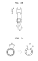
- FIG. 1 is a schematic diagram illustrating a nanoparticle with inorganic ligands (hereinafter, sometimes referred to as “inorganic ligand coated nanoparticle” or “inorganic ligand capped nanoparticle”) 30, according to an embodiment.
- the inorganic ligand coated nanoparticle 30 includes a nanoparticle core 10 which is formed of a semiconductor material; and an inorganic ligand (sometimes referred to as "inorganic coat”) 23 passivated on a surface of the nanoparticle core 10, in which the ligands are a metal chalcogenide complexes (MCC) hydrazine hydrate.
- MCC metal chalcogenide complexes
- the semiconductor material of the nanoparticle core 10 may be formed of, for example, a Group II-VI semiconductor compound, a Group III-V semiconductor compound, a Group IV-VI semiconductor compound, a Group IV element or compound, or a combination thereof.
- the Group II-VI semiconductor compound may be, for example: a binary compound such as CdS, CdSe, CdTe, ZnS, ZnSe, ZnTe, ZnO, HgS, HgSe, HgTe or a combination thereof; a ternary compound such as CdSeS, CdSeTe, CdSTe, ZnSeS, ZnSeTe, ZnSTe, HgSeS, HgSeTe, HgSTe, CdZnS, CdZnSe, CdZnTe, CdHgS, CdHgSe, CdHgTe, HgZnS, HgZnSe or a combination thereof; or a
- the Group III-V semiconductor compound may be: for example, a binary compound such as GaN, GaP, GaAs, GaSb, AlN, AlP, AlAs, AlSb, InN, InP, InAs, InSb or a combination thereof; a ternary compound such as GaNP, GaNAs, GaNSb, GaPAs, GaPSb, AlNP, AlNAs, AlNSb, AlPAs, AlPSb, InNP, InNAs, InNSb, InPAs, InPSb or a combination thereof; or a quaternary compound such as GaAlNAs, GaAlNSb, GaAlPAs, GaAlPSb, GaInNP, GaInNAs, GaInNSb, GaInPAs, GaInPSb, InAlNP, InAlNAs, InAlNSb, InAlPAs, InAlPSb or a combination thereof.
- the Group IV-VI semiconductor compound may be: for example, a binary compound such as SnS, SnSe, SnTe, PbS, PbSe, PbTe or a combination thereof; a ternary compound such as SnSeS, SnSeTe, SnSTe, PbSeS, PbSeTe, PbSTe, SnPbS, SnPbSe, SnPbTe or a combination thereof; or a quaternary compound such as SnPbSSe, SnPbSeTe, SnPbSTe or a combination thereof.
- the Group IV element or compound may be, for example, Si, Ge, SiC, SiGe, or a combination thereof.
- the nanoparticle 10 may have a core-shell structure.
- Each of the core 11 and the shell 12 may be formed of a single layer or of two or more layers.
- nanoparticle 10 may be formed of CdSe/ZnS or CdSe/CdS/ZnS.
- the MCC hydrazine hydrate is coordinatively bonded to the surface of the nanoparticle 10 to form a coat 23.
- the metal chalcogenides complex or MCC of the MCC hydrazine hydrate, suitable as an inorganic ligand are compounds consisting of a metal and an element which is a member of the chalcogen column of the periodic table. While oxygen is a member of the chalcogens, the term metal chalcogenide used in the instant application with regard to an inorganic ligand refers to compounds of a metal with sulfur, selenium, tellurium, or polonium.
- Exemplary metals include Ga, In, Ti, Sn, Pb, Bi, Zn, Cd, Hg, Cu, Ag, Au, Ni, Pd, Pt, Co, Rh, Ir, Fe, Ru, Os, Mn, Tc, Re, Cr, Mo, W,V, Nb, Ta, Ti, Zr, Hf, Sc, and Y.
- Metal chalcogenides may include a semiconductor cadmium sulfide, cadmium selenide, Sn 2 S 6 , Sn 2 Se 6 , In 2 Se 4 , In 2 Te 3 , Ga 2 Se 3 , CuInSe 2 , Cu 7 S 4 , Hg 3 Se 4 , Sb 2 Te 3 , or ZnTe.
- Sn 2 S 6 , Sn 2 Se 6 , In 2 Se 4 , In 2 Te 3 , Ga 2 Se 3 , CuInSe 2 , Cu 7 S 4 , Hg 3 Se 4 , Sb 2 Te 3 , or ZnTe may be usefully employed in embodiments of the invention.
- the MCC as an inorganic ligand to be bound by a coordinate bond to the surface of the core or the shell of a core-shell or core-shell-shell nanoparticle is different from the semiconducting metal chalcogenide forming the core or the shell.
- Exemplary hydrazine hydrates may include, but are not limited to, monohydrate, dihydrate, trihydrate, tetrahydrate, pentahydrate, or hexahydrate of hydrazine.
- Exemplary hydrazine solvates may include, but are not limited to, hydrazine dihydrochloride (N 2 H 4 -2HCI), hydrazine monohydrochloride, hydrazine monohydrobromide or hydrazine acetate.
- a nanoparticle solution may be provided by dissolving the nanoparticles 30 described above in an organic solvent such as ethanolamine, dimethyl sulfoxide (DMSO), dimethylformamide (DMF), or formamide solvent.
- organic solvent such as ethanolamine, dimethyl sulfoxide (DMSO), dimethylformamide (DMF), or formamide solvent.
- FIG. 2A is an energy diagram illustrating electronic energy of an organic ligand coated nanoparticle 20
- FIG. 2B is an energy diagram illustrating electronic energy of an inorganic ligand coated nanoparticle 30.
- energy levels of organic ligand coat 21 of the organic ligand coated nanoparticle 20, which is composed of a nanoparticle 10 formed of a core 11 and a shell 12 and the organic ligands 21 on the surface of the nanoparticle 10 are relatively higher than energy levels of the core 11 and the shell 12.
- FIG. 2A energy levels of organic ligand coat 21 of the organic ligand coated nanoparticle 20, which is composed of a nanoparticle 10 formed of a core 11 and a shell 12 and the organic ligands 21 on the surface of the nanoparticle 10.
- the nanoparticle with the inorganic ligands 30, which is composed of a nanoparticle 10 formed of a core 11 and a shell 12 and the inorganic ligands 23 on the surface of the nanoparticle 10, has lower energy levels of the inorganic ligands 23 than energy levels of the shell 12. Therefore, inorganic ligands-coated nanoparticles do not have a high energy barrier caused by organic ligands 21 of organic ligands-passivated nanoparticle 20, and thus can have an improved conductivity.
- FIG. 3 is a diagram conceptually illustrating a method of manufacturing nanoparticles coated with inorganic ligands, according to an embodiment.
- a nanoparticle coated with inorganic ligands 30 may be prepared by providing organic ligands-passivated nanoparticles, and replacing organic ligands 21 of the organic ligands-passivated nanoparticle 10 with inorganic ligands 23.
- the inorganic ligands 23 may be an MCC hydrazine hydrate.
- the substitution of organic ligands with inorganic ligands may be done via phase transfer between a first solution or dispersion comprising inorganic ligand compounds and a second solution or dispersion comprising nanoparticles coated with organic ligands of a solvent system.
- the substitution of ligands may be done in a solvent system comprising a single solvent where nanoparticles coated with organic ligands and an excess amount of inorganic ligand compounds are present.
- FIG. 4 is a flowchart for describing a method of manufacturing nanoparticles coated with MCC hydrazine hydrate ligands, according to an embodiment.
- an MCC hydrazine hydrate solution (solution A) is prepared (S110).
- the MCC hydrazine hydrate is a compound comprised of an MCC and hydrazine hydrate, which are bound to each other.
- the MCC hydrazine hydrate may be dissolved or dispersed into an appropriate solvent to give an MCC hydrazine hydrate solution.
- a chalcogen hydrazine hydrate solution or chalcogen hydrazine hydrate dispersion is prepared by dissolving or dispersing chalcogen powder (nonlimiting examples include S, Se, or Te) in hydrazine hydrate (N 2 H 4 ⁇ nH 2 O).
- sulfur powder may be dissolved in a hydrazine hydrate solution to prepare a sulfur hydrazine monohydrate solution.
- hydrazine monohydrate may contain about 60-70, or about 64-65 wt% hydrazine.
- hydrazine hydrates may contain about 50-60 wt%, or about 55% hydrazine. It can be used as a diluted solution or a stock solution.
- a hydrazine hydrate solution containing hydrazine up to 65 wt% may be diluted to 1 M solution.
- the metal may include a metal element or a metal compound.
- the metal may include Sn, Ga, Cu 2 S, GeS, Sb 2 Se 3 , Sb 2 Te 3 , In 2 Se 3 , ZnTe, In 2 Te 3 , etc.
- An additional hydrazine hydrate solution along with the metal powder may be added.
- the reaction temperature may be in a range from room temperature to about 200°C. Since hydrazine hydrate is a strong reducing agent, MCC may be synthesized in the hydrazine hydrate solution.
- the MCC may bind to the hydrazine hydrate in the hydrazine hydrate solution to form MCC hydrazine hydrate.
- the MCC hydrazine hydrate may be an MCC hydrazine monohydrate, MCC hydrazine dihydrate, MCC hydrazine trihydrate, MCC hydrazine tetrahydrate, MCC hydrazine pentahydrate, MCC hydrazine hexahydrate, or a combination thereof.
- the hydrazine hydrate solution may be safely used in MCC synthesis due to its less toxicity than hydrazine and non-explosiveness.
- the MCC hydrazine hydrate solution (“solution A”) may be prepared by removing precipitates from the reaction mixture using, for example, centrifugation or filtration after the reaction.
- hydrazine hydrate is employed as a solvent for the MCC hydrazine hydrate solution.
- a hydrazine monohydrate solution of Sn 2 S 6 , Sn 2 Se 6 , In 2 Se 4 , In 2 Te 3 , Ga 2 Se 3 , CuInSe 2 , Cu 7 S 4 , Hg 3 Se 4 , Sb 2 Te 3 , or ZnTe may be prepared.
- a first organic solution or dispersion containing first organic ligand-capped nanoparticle (“solution B") is prepared (S120).
- the solution B is a solution in which nanoparticles capped with first organic ligands are dissolved or dispersed in a first organic solvent.
- a nanoparticle may be formed of, for example, a Group II-VI semiconductor compound, a Group III-V semiconductor compound, a Group IV-VI semiconductor compound, a Group IV element or compound, or a combination thereof.
- the Group II-VI semiconductor compound may be: for example a binary compound such as CdS, CdSe, CdTe, ZnS, ZnSe, ZnTe, ZnO, HgS, HgSe, HgTe, or a combination thereof; a ternary compound such as CdSeS, CdSeTe, CdSTe, ZnSeS, ZnSeTe, ZnSTe, HgSeS, HgSeTe, HgSTe, CdZnS, CdZnSe, CdZnTe, CdHgS, CdHgSe, CdHgTe, HgZnS, HgZnSe, or a combination thereof; or a quaternary compound such as CdHgZnTe, CdZnSeS, CdZnSeTe, CdZnSTe, CdHgSeS, CdHgSeTe, CdH
- the Group III-V semiconductor compound may be, for example: a binary compound such as GaN, GaP, GaAs, GaSb, AlN, AlP, AlAs, AlSb, InN, InP, InAs, InSb, or a combination thereof; a ternary compound such as GaNP, GaNAs, GaNSb, GaPAs, GaPSb, AlNP, AlNAs, AlNSb, AlPAs, AlPSb, InNP, InNAs, InNSb, InPAs, InPSb, GaAlNP, or a combination thereof; or a quaternary compound such as GaAlNAs, GaAlNSb, GaAlPAs, GaAlPSb, GaInNP, GaInNAs, GaInNSb, GaInPAs, GaInPSb, InAlNP, InAlNAs, InAlNSb, InAlPAs, InAlPSb, or a combination thereof.
- the Group IV-VI semiconductor compound may be: for example, a binary compound such as SnS, SnSe, SnTe, PbS, PbSe, PbTe, or a combination thereof; a ternary compound such as SnSeS, SnSeTe, SnSTe, PbSeS, PbSeTe, PbSTe, SnPbS, SnPbSe, SnPbTe, or a combination thereof; a quaternary compound such as SnPbSSe, SnPbSeTe, SnPbSTe, or a combination thereof.
- the Group IV element or compound may be, for example, Si, Ge, SiC, SiGe, or a combination thereof.
- the nanoparticle may have a structure of core/shell/shell of CdSe/CdS/ZnS.
- the nanoparticles are dispersed in the form of colloid in the first organic solution, and the first organic ligands are coordinately bonded on surfaces of the nanoparticles. That is, each of the nanoparticles is passivated with the first organic ligands.
- the first organic ligands may include trioctylphosphine (TOP), trioctylphosphine oxide (TOPO), oleic acid, oleylamine, octylamine, trioctylamine, hexadecylamine, octanethiol, dodecanethiol, hexylphosphonic acid (HPA), tetradecylphosphonic acid (TDPA), octylphosphonic acid (OPA) or a combination thereof.
- TOP trioctylphosphine
- TOPO trioctylphosphine oxide
- the first solvent may include, but is not limited thereto, cyclohexane, hexane, chloroform, toluene, octane, chlorobenzene or a combination thereof.
- the first solvent may be the same compound as the first organic ligands.
- the first organic ligands of the nanoparticles may be replaced with the MCC hydrazine hydrate ligands by a phase transfer reaction, for example by mixing the solution B with solution A (S130).
- the phase transfer may be performed by mixing solution B and solution A with stirring, vortex, agitation, or combinations thereof.
- the phase transfer may be promoted by adding hydrazine hydrate solution to the mixture.
- solution A may be added to a hydrazine hydrate solution, followed by the addition of the first organic solution of the first organic ligand-capped nanoparticles.
- Thy hydrazine hydrate solution may be hydrazine monohydrate, hydrazine dihydrate, hydrazine trihydrate, hydrazine tetrahydrate, hydrazine pentahydrate, hydrazine hexahydrate, or a combination thereof.
- the solvent (i.e., hydrazine hydrate) of the MCC hydrazine hydrate solution (or dispersion) is immiscible with the solvent for the first organic ligand capped nanoparticle solution, when two solutions are combined, it is separated into two layers (or phases): a first organic solution layer of an upper portion and a hydrazine hydrate layer of a lower portion.
- the first organic solution layer of the upper portion may include the first organic ligands-capped nanoparticles, and the hydrazine hydrate layer of the lower portion may include an excess amount of MCC.
- the organic ligands capped nanoparticles in the first organic solution layer move to the hydrazine hydrate layer, and the organic ligands passivating the nanoparticles may be replaced with the MCC hydrazine hydrate ligands.
- the stirring temperature may be in a range from room temperature to 200°C.
- nanoparticles By allowing the nanoparticles to move between two phases of immiscible solvents of a solvent system, substitution of ligands which are bound to the surface of the nanoparticles occurs, giving nanoparticles of a semiconductor compound passivated with MCC hydrazine hydrate ligands.
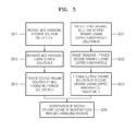
- FIG. 5 is a flowchart schematically describing a method of manufacturing nanoparticles capped with MCC hydrazine hydrate ligands, according to another embodiment.
- the current embodiment is different from the embodiment of FIG. 4 in the sense of replacing the solvent of the first MCC hydrazine hydrate solution, exchanging organic ligands of a nanoparticle to new organic ligands, followed by converting the solvent of the nanoparticle solution.
- an MCC hydrazine hydrate solution (solution A) is prepared (S211).
- the process is as same as the preparation process S110 of the MCC hydrazine hydrate solution described in regard to the embodiment of FIG 4 .
- the MCC hydrazine hydrate is separated from the solution A (S212).
- the MCC hydrazine hydrate is a compound composed of MCC and hydrazine hydrate.
- the MCC hydrazine hydrate may be separated from hydrazine hydrate solvent by blowing an inert gas such as nitrogen gas to the solution A to evaporate hydrazine hydrate solvent.
- an excessive amount of a solvent which does not dissolve MCC may be added to solution A , and then solution A may be centrifuged to separate the MCC hydrazine hydrate.
- the solvent which does not dissolve MCC methanol, ethanol, butanol, or acetonitrile may be exemplified.
- a second solution (or dispersion) of MCC hydrazine hydrate may be prepared by dispersing the separated MCC hydrazine hydrate in a second solvent, which may be an organic solvent (S213).
- the solvent may be an organic solvent that may dissolves (disperses) both MCC and nanoparticles.
- the second solvent may be an organic solvent with a polarity, such as ethanolamine, DMSO (dimethylsulfoxide), DMF(dimethylformamide), formamide, etc.
- a first solution of the first organic ligand-capped nanoparticle (solution B) is prepared (S221).
- the process is as same as the preparation process S121 of the solution B described in regard to the embodiment of FIG 4 .
- first organic ligands are replaced with second organic ligands via phase transfer of the nanoparticles (S222).
- the solution B may be added and stirred in a third organic solution including an excess amount of the second organic ligands.
- the second organic ligands are ligands that may be dissolved or dispersed in a second organic solvent which may dissolve (or disperse) MCC hydrazine hydrate.
- the second organic ligands may be ligands with a polarity such as mercaptopropionic acid (MPA), cysteamine, mercaptoacetic acid, etc.
- the third organic solvent may be, for example, chloroform, chlorobenzene, etc.
- the first organic ligands of the nanoparticles are replaced with the second organic ligands due to an equilibrium reaction in the third organic solution including an excess amount of the second organic ligands.
- the second organic ligands may be dissolved in both the second organic solvent and the third organic solvent. Since the second organic ligands may be dissolved in the second organic solvent in which MCC hydrazine hydrate is dissolved, the substitution of ligands of nanoparticles in the same type of solvent is enabled.
- Nanoparticles capped with the second ligands are dispersed in a second organic solvent to prepare a second organic solution of the second organic ligand-capped nanoparticles (solution D) (S223).
- solution D a second organic solution of the second organic ligand-capped nanoparticles
- the nanoparticles capped with the second organic ligands are separated from the third organic solution.
- the third organic solution including the nanoparticles capped with the second organic ligands is centrifuged to precipitate and separate the nanoparticles.
- the solution D may be prepared by dispersing the separated nanoparticles in an organic solvent which is the same as the second organic solvent in which MCC hydrazine hydrate are dissolved (or dispersed) in (S213).
- the second organic ligands of the nanoparticles are replaced with the MCC hydrazine hydrate ligand by forming a solvent system by mixing the solution D into the solution C (S230). Mixing the solution C and the solution D does not cause a phase separation because the solvents of the solutions are the same. Since a phase separation does not occur, byproducts at the interface between the hydrazine hydrate solution and the first organic solution are not produced, and thus, damage on surfaces of the nanoparticles due to the byproducts which may be produced during the replacement of ligands of the nanoparticles may be prevented.
- hydrazine hydrate as a solvent which by itself may reduce a luminescence efficiency of nanoparticles is not present during the formation of MCC hydrazine hydrate-capped nanoparticles, a reduction in luminescence efficiency may be inhibited.
- the second organic ligands passivating the nanoparticle may be replaced with the MCC hydrazine hydrate ligands by stirring, vortex, or agitating the mixed solution.
- the stirring temperature may be in a range between room temperature to 200°C.
- the second organic ligands passivating the nanoparticles in the second organic solution may be replaced with the MCC hydrazine hydrate ligands in the same solvent. Therefore, a nanoparticle of a semiconductor compound passivated with the MCC hydrazine hydrate ligands may be manufactured by the ligands replacement in a single solvent.
- the current embodiment uses the same organic solvents for solution C containing MCC hydrazine hydrate ligands and for solution D containing organic ligands-capped nanoparticles, a sub-reaction at an interface between different solvents does not occur. Also, the current embodiment may have a broader applicability because various factors limiting the applicability of phase transfer reaction, including for example, selecting a degree of polarity of each solvent and portions of the solvents are not applied to this method.
- FIG. 6 is a flowchart for describing a method of manufacturing nanoparticles capped with MCC hydrazine hydrate ligands, according to another embodiment.
- the present embodiment is different from the embodiment of FIG. 4 in the sense that the solvent of an MCC hydrazine hydrate solution is replaced with a second organic solvent.
- the current embodiment is different from the embodiment of FIG. 5 in the sense of not performing a surface reforming of a nanoparticle (S222) and a solvent replacement of a nanoparticle solution (S223).
- an MCC hydrazine hydrate solution (solution A) is prepared (S311).
- MCC hydrazine hydrate is isolated from the solution A (S312).
- a second organic solution of MCC hydrazine hydrate (solution C) is prepared by dispersing the separated MCC hydrazine hydrate in a second organic solvent (S313).
- S311, S312, and S313 is same as each procedure of S211, S212, and S213 explained in regard to the embodiment of FIG. 5 , except that the second organic solvent is not required to dissolve both of MCC hydrazine hydrate and first organic ligands-capped nanoparticles.
- An organic solvent which dissolves both of MCC hydrazine hydrate and nanoparticles of which surfaces are reformed with MCC hydrazine hydrate may also be used.
- a first organic solution of the first organic ligand-capped nanoparticles (solution B) is prepared (S321).
- the procedure is the same as the preparation procedure S121 of the solution B explained in regards to the embodiment of FIG. 4 .
- the current embodiment does not perform the procedures of substituting the first organic ligands with second organic ligands and replacing a solvent of a nanoparticle solution.
- the first organic ligands of the nanoparticle are substituted with the ligands of the MCC hydrazine hydrate by forming a solvent system by mixing the solution B into the solution C (S330). Phase separation may occur due to different solvents of the solution C and the solution B. For example, phase separation may occur when the solution C is polar, while the solution B is non-polar.
- the first organic ligands passivating the nanoparticle may be replaced with the MCC hydrazine hydrate ligands by stirring, vortex, agitating the combined solution.
- the nanoparticle in a first organic solution layer moves to a second organic solution layer, thus the first organic ligands passivating the nanoparticle may be replaced with the MCC hydrazine hydrate ligands.
- the stirring temperature may be in the range between room temperature to 200°C. Therefore, the nanoparticles of a semiconductor compound passivated with the MCC hydrazine hydrate may be prepared by ligands exchange in the different solvents.
- impurities may be formed at the interface between the two different solvents due to a remnant of the first organic ligands and an imperfect ligands exchange reaction.
- the amount of the impurities formed is less than the amount of sub-reaction substance produced at the interface between the hydrazine hydrate solvent and the first organic solvent. It is speculated that the strong reducing power of hydrazine hydrate as a solvent may affect the surface of the nanoparticles. In the current embodiment, a reduction in the luminous efficiency of the nanoparticles due to the hydrazine hydrate solvent may be inhibited.
- the omission of the substitution of first organic ligands with second organic ligands of nanoparticles according to the current embodiment is expected to minimize any reduction in luminous efficiency which could occur due to a ligands substitution reaction, and the number of an entire reaction process is reduced, thus the overall ligand substitution may be fast and convenient.
- 1 M of sulfur hydrazine monohydrate solution was prepared by dissolving 0.32 g (10 mmol) of sulfur powder in 10 mlof hydrazine monohydrate solution (hydrazine content 64-65 wt%). 120 mg (1 mmol) of tin (Sn) powder was added to a mixed solution of 3 ml of the 1 M of sulfur hydrazine monohydrate solution and 1 ml of the hydrazine monohydrate and the mixture was allowed to react. The reaction took place at room temperature and the solution was stirred for about an hour. At the end of the reaction, a Sn 2 S 6 hydrazine monohydrate solution was obtained by centrifugation to remove remaining precipitates from the reaction solution. The Sn 2 S 6 hydrazine monohydrate solution contained Sn 2 S 6 hydrazine monohydrate of which Sn 2 S 6 and hydrazine monohydrate are bound to each other.
- a CdSe/CdS/ZnS nanoparticle cyclohexane solution with concentration of 5 mg/ml was prepared by dissolving (or dispersing) CdSe/CdS/ZnS nanoparticles in a cyclohexane solution by following a known method, for example the process reported in Advanced Materials, 2007, 19, 1927-1932 .
- the CdSe/CdS/ZnS nanoparticle has a structure of CdSe core/ CdS inner shell/ ZnS outer shell.
- the CdSe/CdS/ZnS nanoparticles are capped with mixed organic ligands of oleic acid, trioctylphosphine ("TOP”), trioctylphosphine oxide (“TOPO”), trioctylamine, etc.
- TOP trioctylphosphine
- TOPO trioctylphosphine oxide
- trioctylamine etc.
- the phase-separated mixed solution was stirred for 72 hours at room temperature. After the stirring, the CdSe/CdS/ZnS nanoparticles were moved from the upper portion of the cyclohexane layer to the lower portion of the hydrazine monohydrate layer. While CdSe/CdS/ZnS nanoparticles were moving from the cyclohexane layer to the hydrazine monohydrate layer, the mixed organic ligands on the surface of CdSe/CdS/ZnS nanoparticles were exchanged with the Sn 2 S 6 hydrazine monohydrate ligands.
- FIG. 7 is a Fourier transform infrared spectroscopy (FTIR) spectrum of the CdSe/CdS/ZnS nanoparticles before and after ligands exchange of Example 1.
- the nanoparticles before ligands exchange were the CdSe/CdS/ZnS nanoparticles containing the mixed organic ligands
- the nanoparticles after the ligands substitution were the CdSe/CdS/ZnS nanoparticles after the reaction exchanging to the Sn 2 S 6 hydrazine monohydrate ligand.
- the FTIR spectrum regarding each powder of nanoparticles was measured.
- a luminous efficiency of the CdSe/CdS/ZnS nanoparticles after ligands substitution of Example 1 was reduced to a level of about 25 % of the CdSe/CdS/ZnS nanoparticles before ligands substitution.
- Such a reduction in the luminous efficiency of the CdSe/CdS/ZnS nanoparticles is speculated to be caused by damage on the surfaces of nanoparticles when the nanoparticles ligands were substituted as subreaction substances at an interface between the hydrazine monohydrate layer and the cyclohexane layer were produced.
- a possibility that the hydrazine monohydrate itself may reduce the luminous efficiency of the nanoparticles may not be excluded.
- a Sn 2 S 6 hydrazine monohydrate solution was prepared with the same procedures in Example 1.
- the Sn 2 S 6 hydrazine monohydrate solution was dried with N 2 gas to remove hydrazine monohydrate solvent to leave Sn 2 S 6 hydrazine monohydrate.
- the separated Sn 2 S 6 hydrazine monohydrate was dissolved in ethanolamine to give an ethanolamine solution of Sn 2 S 6 hydrazine monohydrate at a concentration of 16 mg/ml.
- a CdSe/CdS/ZnS nanoparticle cyclohexane solution with a concentration of 10 mg/ml was prepared by following the procedures of Example 1. 2 ml of the CdSe/CdS/ZnS nanoparticle cyclohexane solution was added to 18 ml of 2M mercapto propionic acid (MPA) solution and stirred at 80°C for 3 hours. Due to the reaction, mixed organic ligands of the surface of the CdSe/CdS/ZnS nanoparticles were replaced with MPA ligands.
- MPA 2M mercapto propionic acid
- CdSe/CdS/ZnS nanoparticles exchanged with MPA ligands were precipitated by centrifugation.
- the precipitated CdSe/CdS/ZnS nanoparticles were re-dispersed(re-dissolved) in an ethanolamine to prepare a CdSe/CdS/ZnS nanoparticle ethanolamine solution with a concentration of 10 mg/ml.
- FIG. 8 is an FTIR spectrum of CdSe/CdS/ZnS nanoparticles before and after a ligands substitution reaction of Example 2.
- the nanoparticles before the ligands substitution were CdSe/CdS/ZnS nanoparticles with MPA ligands, and the nanoparticles after the ligands substitution were CdSe/CdS/ZnS nanoparticles after the replacement reaction with Sn 2 S 6 hydrazine monohydrate ligands.
- the FTIR spectrum regarding each powder of nanoparticles was measured.
- a luminous efficiency of the CdSe/CdS/ZnS nanoparticles after ligands exchange of Example 2 was reduced to a level of about 60% of the CdSe/CdS/ZnS nanoparticles with the mixed organic ligands.
- Such reduction in the luminous efficiency of the CdSe/CdS/ZnS nanoparticles is speculated to be caused by a reduction in a luminescence quantum yield during the substitution process of the ligands of the CdSe/CdS/ZnS nanoparticles with the MPA and the substitution process of the MPA with the ligands of the Sn 2 S 6 hydrazine monohydrate.
- a Sn 2 S 6 hydrazine monohydrate ethanolamine solution with a concentration of 16 mg/ml was prepared with the same procedures in Example 2.
- a CdSe/CdS/ZnS nanoparticle cyclohexane solution with a concentration of 10 mg/ml was prepared with the same procedures of Example 1.
- 0.2 ml of the Sn 2 S 6 hydrazine monohydrate ethanolamine solution prepared in (a) was added to 2 ml of ethanolamine.
- 0.2 ml of the CdSe/CdS/ZnS nanoparticle cyclohexane solution prepared in (b) was added to 2 ml of cyclohexane, then mixed with the Sn 2 S 6 hydrazine monohydrate ethanolamine solution and reacted for ligands exchange while stirring for 8 hours at room temperature.
- FIG. 9 is an FTIR spectrum of CdSe/CdS/ZnS nanoparticles before and after a ligands exchange reaction of Example 3.
- the nanoparticles before the ligands exchange were the CdSe/CdS/ZnS nanoparticles with the mixed organic ligands
- the nanoparticles after the ligands exchange were the CdSe/CdS/ZnS nanoparticles after an exchange reaction to the Sn 2 S 6 hydrazine monohydrate ligands.
- the FTIR spectrum regarding each powder of nanoparticles was measured.
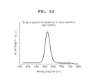
- FIG. 10 is a photoluminescence (PL) spectrum of the CdSe/CdS/ZnS nanoparticles of Example 3 after ligands substitution. After the ligand substitution, the PL spectrum was measured for the CdSe/CdS/ZnS nanoparticles with the Sn 2 S 6 hydrazine hydrate ligands dissolved (dispersed) in ethanolamine. Also, referring to FIG. 10 , a luminescence quantum yield (QY) of the Sn 2 S 6 hydrazine hydrate ligand-capped CdSe/CdS/ZnS nanoparticles after ligands substitution was 68 %.
- QY luminescence quantum yield
- Inorganic ligands-capped CdSe/ZnS nanoparticles prepared using a hydrazine showed reduction to a level of about 40-50 % of photoluminescence intensity, compared to the same nanoparticles, and a luminescence (QY) was 35-41 %. (refer to J. Am. Chem. Soc., 2010, 132 (29), pp 10085-10092 ).
- the QY of the CdSe/CdS/ZnS nanoparticles capped with the Sn 2 S 6 hydrazine hydrate ligands of Example 3 was higher than that of the inorganic ligand-capped CdSe/ZnS nanoparticles of the above article.
- Such an increase in the QY of MCC hydrazine hydrate-capped nanoparticles obtained by the processes described in various embodiments may be attributed to the feature of the processes that the hydrazine hydrate solvent does not directly affect the preparation of nanoparticles capped with MCC hydrazine hydrate which increases a photoluminescence efficiency.
- the FTIR spectra were recorded on a Varian 670-IR spectrophotometer from Varian Inc., and the photoluminescence spectra were recorded on a F-7000 fluorescence spectrophotometer from Hitachi High-Technologies.
Landscapes
- Engineering & Computer Science (AREA)
- Chemical & Material Sciences (AREA)
- Power Engineering (AREA)
- Microelectronics & Electronic Packaging (AREA)
- Nanotechnology (AREA)
- Physics & Mathematics (AREA)
- Condensed Matter Physics & Semiconductors (AREA)
- General Physics & Mathematics (AREA)
- Organic Chemistry (AREA)
- Crystallography & Structural Chemistry (AREA)
- Ceramic Engineering (AREA)
- Computer Hardware Design (AREA)
- Inorganic Chemistry (AREA)
- Materials Engineering (AREA)
- Manufacturing & Machinery (AREA)
- Mathematical Physics (AREA)
- Theoretical Computer Science (AREA)
- Composite Materials (AREA)
- Luminescent Compositions (AREA)
- Powder Metallurgy (AREA)
- Manufacturing Of Micro-Capsules (AREA)
Abstract
Description
- The present disclosure relates to nanoparticles and methods of manufacturing the same, and more particularly, to nanoparticles comprising an inorganic capping agent and methods of manufacturing the same.
- A quantum dot (sometimes abbreviated as "QD" throughout the application) or a nanocrystal is a crystal structure of a dimension from a few to several ten nanometers, of which properties vary depending on its size. A semiconductor QD demonstrates properties between those of bulk semiconductors of the same material and those of discontinuous molecules. Since its physical, chemical, and electrical properties may be controlled by changing the size of the same material due to quantum confinement effects and large surface to volume ratios, a nanoparticle has received great interest for a new method of controlling properties of a material and a new material.
- A typical nanoparticle, of which dimension varies from several to several hundred nanometers, may be comprised of two or three main parts: the middle core part which is a single crystal, of which the diameter may be about one to several ten nanometers, a shell or multiple shells, and a coating region or a coating layer of ligands formed on a surface of the core or the shell. Among preparation methods of nanoparticles, a wet-chemical synthesis method, which makes colloidal nanoparticle core, may produce a mass amount of uniformly nanosized particles at a low cost.
- Single-core semiconductor nanoparticles, which contain a single semiconductor material along with an outer organic passivating (or capping) layer, may have relatively low quantum efficiencies due to electron-hole recombination occurring at defects and dangling bonds situated on the nanoparticle surface.
- One method to eliminate defects and dangling bonds is to grow a second inorganic material, having a wider band-gap and smaller lattice mismatch to that of the core material, epitaxially on the surface of the core particle to produce a "core-shell" particle. One example is ZnS grown on the surface of a CdSe core to provide a CdSe/ZnS nanoparticle.
- Another approach is to prepare a core/multi-shell structure where the "electron-hole" pair is confined to a single shell layer such as the quantum dot-quantum well structure. One example of such core/shell/shell structured nanoparticle is CdS/HgS/CdS.
- The coordination about the final inorganic surface atoms in core, core/shell or core/multi shell nanoparticle is generally incomplete, with highly reactive atoms that are not fully coordinated leaving "dangling bonds" on the surface of the particle, which may lead to particle agglomeration. To overcome this problem, the core, core/shell or core/multishell is passivated (capped) with protecting organic groups. The outermost layer (or capping agent) of organic material helps to inhibit particle aggregation and also further protects the nanoparticle from its surrounding chemical environment. It also provides chemical linkage to other inorganic, organic or biological material.
- However, the organic passivating layer (or capping layer) coated on a surface of the core or the shell of the nanoparticle act as an insulating barrier layer, causing a decrease in electric conductivity of the nanoparticle, which limits actual industrial applications of the semiconductor nanoparticles to various electronic devices such as a light-emitting diode, a solar cell, a transistor, and the like. If the organic capping layer is removed, a luminous efficiency of the nanoparticles may decline due to effects of dangling bonds, surface defects, etc. on the surface of the nanoparticle, or optical and electrical properties may decline due to charge carriers trapped on the surface of the nanoparticle. Also, removing the organic capping layer causes aggregation or fusion of nanoparticles and destabilizes the nanoparticles.
- Recently, Science 2009, 324, 1417-1420 reported a research about replacing organic ligands of nanoparticles with metal chalcogenide complexes ("MCC"). The MCC have an electrical charge, and like the organic ligands, they function as a capping agent to form a coating layer on the surface of the nanoparticles in a solution and stabilize the colloidal nanoparticles in the solution. However, the research uses a hydrazine solvent which is highly toxic and highly explosive when exposed to air, which makes it difficult to apply the method to industrial fabrication process.
- Therefore, there is a need for a safe and efficient fabrication method of nanoparticles with an inorganic capping layer.
- Provided is nanoparticles with an inorganic capping layer which have a good electrical conductivity and stability.
- Provided is a method of manufacturing nanoparticles with an inorganic capping layer which have a good electrical conductivity and stability in a less toxic and safe way.
- Additional aspects will be set forth in part in the description which follows and, in part, will be apparent from the description, or may be learned by practice of the presented embodiments.
- According to an embodiment, there is provided a method for producing nanoparticles comprising inorganic ligands, the method including replacing organic ligands coupled to a surface of nanoparticles with the inorganic ligands to give the nanoparticles containing the inorganic ligands coupled to a surface of the nanoparticles, wherein the replacement is performed in a solvent containing the inorganic ligands and the nanoparticles coupled with the organic ligands, and wherein the inorganic ligands are a hydrazine hydrate of metal chalcogenide complex.
- The solvent may be a mixed solvent of a first solvent which contains the metal chalcogenide complex hydrazine hydrate dissolved therein and a second solvent which contains the nanoparticles coupled with the organic ligands dissolved therein. The replacement is performed by stirring the mixed solvent. According to the current embodiment, the first solvent may be different from the second solvent, or may be the same as the second solvent. For example, the first solvent may be a hydrazine hydrate and the second solvent may be an organic solvent. In another exemplary embodiment, the first solvent may be a polar organic solvent and the second solvent may be a non-polar organic solvent. The first solvent and the second solvent may be the same and may include a polar organic solvent. The polar organic solvent may be one which dissolves or disperses the metal chalcogenide complex hydrazine hydrate and the nanoparticles coupled with the organic ligands. According to another aspect of the present invention, nanoparticles each may include a nanoparticle core of a semiconductor material; and an inorganic capping layer including hydrazine hydrate on a surface of the nanoparticle core.
- According to another aspect of the present invention, there is provided a method for producing nanoparticles comprising inorganic ligands, the method comprising replacing organic ligands coupled to a surface of nanoparticles with the inorganic ligands to give the nanoparticles comprising the inorganic ligands coupled to a surface of the nanoparticles, wherein the replacement is performed in a solvent system comprising the inorganic ligands and the nanoparticles coupled with the organic ligands, and wherein the inorganic ligands are a metal chalcogenide complex hydrazine hydrate.
- In an embodiment, the method further comprises providing a first solution comprising a metal chalcogenide complex (MCC) hydrazine hydrate in a first solvent; providing a first organic solution of nanoparticles capped with first organic ligands in a first organic solvent; and mixing the MCC hydrazine hydrate solution and the first organic solution of the first organic ligands-capped nanoparticles to form the solvent system.
- In another embodiment, solution comprising a metal chalcogenide complexes (MCC) hydrazine hydrate comprises an organic solvent.
- In yet another embodiment, the method further comprising providing a first further organic solution of nanoparticles capped with first further organic ligands; stirring the first further organic solution with a second further organic solution comprising an excess amount of the first organic ligands dispersed or dissolved therein, thereby forming nanoparticles capped with the first organic ligands by replacing the first further organic ligands with the first organic ligands; separating the nanoparticles capped with the first organic ligands from the second further organic solution; and dispersing or dissolving the nanoparticles capped with the first organic ligands in the first organic solvent to form the first organic solution.
- By substituting organic ligands of organic ligands-capped nanoparticles with inorganic ligands such as MCC hydrazine hydrate, electrical properties of the nanoparticles may be improved, and the use of a solvent other than hydrazine allows manufacturing inorganic ligand-capped nanoparticles, in a less toxic and safe way.
- These and/or other aspects will become apparent and more readily appreciated from the following description of the embodiments, taken in conjunction with the accompanying drawings of which:
-
FIG. 1 is a schematic diagram illustrating an inorganic ligand-capped nanoparticle, according to an embodiment; -
FIG. 2A is an energy diagram illustrating electronic energy of an organic ligand-capped nanoparticle; -
FIG. 2B is an energy diagram illustrating electronic energy of an inorganic ligand-capped nanoparticle, according to an embodiment; -
FIG. 3 is a diagram conceptually illustrating a method of manufacturing an inorganic ligand-capped nanoparticle, according to an embodiment; -
FIG. 4 is a flowchart for describing a method of manufacturing an MCC hydrazine hydrate ligand-capped nanoparticle, according to an embodiment; -
FIG. 5 is a flowchart for describing a method of manufacturing an MCC hydrazine hydrate ligand-capped nanoparticle, according to another embodiment; -
FIG. 6 is a flowchart for describing a method of manufacturing an MCC hydrazine hydrate ligand-capped nanoparticle, according to another embodiment; -
FIG. 7 is a Fourier transform infrared spectroscopy (FTIR) spectrum of the CdSe/CdS/ZnS nanoparticle before and after ligands exchange explained in Example 1; -
FIG. 8 is an FTIR spectrum of CdSe/CdS/ZnS nanoparticles before and after a ligands exchange reaction explained in Example 2; -
FIG. 9 is an FTIR spectrum of CdSe/CdS/ZnS nanoparticles before and after a ligands exchange reaction explained in Example 3; and -
FIG. 10 is a photoluminescence (PL) spectrum of the CdSe/CdS/ZnS nanoparticles of Example 3 after ligands exchange. - Reference will now be made in detail to embodiments, examples of which are illustrated in the accompanying drawings, wherein like reference numerals refer to the like elements throughout. In this regard, the present embodiments may have different forms and should not be construed as being limited to the descriptions set forth herein. Accordingly, the embodiments are merely described below, by referring to the figures, to explain aspects of the present description.
- In the present application, the terms "ligand capped nanoparticle(s)," "ligand coated nanoparticle(s)," ligand passivated nanoparticle(s)," "nanoparticle(s) coated with a ligand," "nanoparticle(s) passivated with a ligand," "nanoparticle(s) capped with a ligand," and "nanoparticle(s) coupled with a ligand" are interchangeably used to mean that ligands are coupled or bound to a surface of nanoparticles. Therefore, it is understood that the ligand coat, ligand capping, or ligand passivating layer does not need to be continuous.
- In the present application, the words "solution" and "dispersion" are sometimes interchangeably used to indicate a liquid made of a solute (here, for example, MCC hydrazine hydrate or organic ligand-capped nanoparticles) and a solvent which dissolves or disperses the solute.
- In the present application, the word "stirring" is used to include, but is not limited to, stirring, agitating or vortex a mixed solvent by a various means known in the art so that the desired replacement of ligands on the surface of the nanoparticles may occur.
- Nanoparticles in the present invention refer to nano-sized particles containing an elemental semiconductor or a compound semiconductor composed of particles of a size in a range of up to several ten nanometers. In an embodiment, the nanoparticle may be quantum dot of about 1 nm - about 10 nm. The nanoparticles in the present invention may have a core-shell structure, and each of a core and a shell may be formed of one or more layers. For example, the nanoparticles may have a core-shell or a core-shell-shell structure.
- Phase transfer in the present invention means a phenomenon: when an interface is formed between two liquid phases as in solvent extraction, nanoparticles having first ligands in first liquid phase exchange the first ligands with second ligands in second liquid phase at a liquid interface and transfer to the second liquid phase. Thus, the nanoparticles after phase transfer are present in the second liquid phase and have the second ligands.
- The ligands of the nanoparticles in the present invention may be single compounds or may be formed of 2 or more types of compounds.
- Hereinafter, an inorganic ligand-capped nanoparticles according to an embodiment will be explained in detail.
-
FIG. 1 is a schematic diagram illustrating a nanoparticle with inorganic ligands (hereinafter, sometimes referred to as "inorganic ligand coated nanoparticle" or "inorganic ligand capped nanoparticle") 30, according to an embodiment. Referring toFIG. 1 , the inorganic ligand coatednanoparticle 30 includes ananoparticle core 10 which is formed of a semiconductor material; and an inorganic ligand (sometimes referred to as "inorganic coat") 23 passivated on a surface of thenanoparticle core 10, in which the ligands are a metal chalcogenide complexes (MCC) hydrazine hydrate. - The semiconductor material of the
nanoparticle core 10 may be formed of, for example, a Group II-VI semiconductor compound, a Group III-V semiconductor compound, a Group IV-VI semiconductor compound, a Group IV element or compound, or a combination thereof. The Group II-VI semiconductor compound may be, for example: a binary compound such as CdS, CdSe, CdTe, ZnS, ZnSe, ZnTe, ZnO, HgS, HgSe, HgTe or a combination thereof; a ternary compound such as CdSeS, CdSeTe, CdSTe, ZnSeS, ZnSeTe, ZnSTe, HgSeS, HgSeTe, HgSTe, CdZnS, CdZnSe, CdZnTe, CdHgS, CdHgSe, CdHgTe, HgZnS, HgZnSe or a combination thereof; or a quaternary compound such as CdHgZnTe, CdZnSeS, CdZnSeTe, CdZnSTe, CdHgSeS, CdHgSeTe, CdHgSTe, HgZnSeS, HgZnSeTe, HgZnSTe or a combination thereof. The Group III-V semiconductor compound may be: for example, a binary compound such as GaN, GaP, GaAs, GaSb, AlN, AlP, AlAs, AlSb, InN, InP, InAs, InSb or a combination thereof; a ternary compound such as GaNP, GaNAs, GaNSb, GaPAs, GaPSb, AlNP, AlNAs, AlNSb, AlPAs, AlPSb, InNP, InNAs, InNSb, InPAs, InPSb or a combination thereof; or a quaternary compound such as GaAlNAs, GaAlNSb, GaAlPAs, GaAlPSb, GaInNP, GaInNAs, GaInNSb, GaInPAs, GaInPSb, InAlNP, InAlNAs, InAlNSb, InAlPAs, InAlPSb or a combination thereof. The Group IV-VI semiconductor compound may be: for example, a binary compound such as SnS, SnSe, SnTe, PbS, PbSe, PbTe or a combination thereof; a ternary compound such as SnSeS, SnSeTe, SnSTe, PbSeS, PbSeTe, PbSTe, SnPbS, SnPbSe, SnPbTe or a combination thereof; or a quaternary compound such as SnPbSSe, SnPbSeTe, SnPbSTe or a combination thereof. The Group IV element or compound may be, for example, Si, Ge, SiC, SiGe, or a combination thereof. Thenanoparticle 10 may have a core-shell structure. Each of thecore 11 and the shell 12 (seeFIG. 1 ) may be formed of a single layer or of two or more layers. For example,nanoparticle 10 may be formed of CdSe/ZnS or CdSe/CdS/ZnS. - The MCC hydrazine hydrate is coordinatively bonded to the surface of the
nanoparticle 10 to form acoat 23. The metal chalcogenides complex or MCC of the MCC hydrazine hydrate, suitable as an inorganic ligand, are compounds consisting of a metal and an element which is a member of the chalcogen column of the periodic table. While oxygen is a member of the chalcogens, the term metal chalcogenide used in the instant application with regard to an inorganic ligand refers to compounds of a metal with sulfur, selenium, tellurium, or polonium. Exemplary metals include Ga, In, Ti, Sn, Pb, Bi, Zn, Cd, Hg, Cu, Ag, Au, Ni, Pd, Pt, Co, Rh, Ir, Fe, Ru, Os, Mn, Tc, Re, Cr, Mo, W,V, Nb, Ta, Ti, Zr, Hf, Sc, and Y. Metal chalcogenides may include a semiconductor cadmium sulfide, cadmium selenide, Sn2S6, Sn2Se6, In2Se4, In2Te3, Ga2Se3, CuInSe2, Cu7S4, Hg3Se4, Sb2Te3, or ZnTe. Among these, Sn2S6, Sn2Se6, In2Se4, In2Te3, Ga2Se3, CuInSe2, Cu7S4, Hg3Se4, Sb2Te3, or ZnTe may be usefully employed in embodiments of the invention. The MCC as an inorganic ligand to be bound by a coordinate bond to the surface of the core or the shell of a core-shell or core-shell-shell nanoparticle is different from the semiconducting metal chalcogenide forming the core or the shell. Exemplary hydrazine hydrates may include, but are not limited to, monohydrate, dihydrate, trihydrate, tetrahydrate, pentahydrate, or hexahydrate of hydrazine. Exemplary hydrazine solvates may include, but are not limited to, hydrazine dihydrochloride (N2H4-2HCI), hydrazine monohydrochloride, hydrazine monohydrobromide or hydrazine acetate. - According to another embodiment, a nanoparticle solution may be provided by dissolving the
nanoparticles 30 described above in an organic solvent such as ethanolamine, dimethyl sulfoxide (DMSO), dimethylformamide (DMF), or formamide solvent. -
FIG. 2A is an energy diagram illustrating electronic energy of an organic ligand coatednanoparticle 20, andFIG. 2B is an energy diagram illustrating electronic energy of an inorganic ligand coatednanoparticle 30. Referring toFIG. 2A , energy levels oforganic ligand coat 21 of the organic ligand coatednanoparticle 20, which is composed of ananoparticle 10 formed of acore 11 and ashell 12 and theorganic ligands 21 on the surface of thenanoparticle 10, are relatively higher than energy levels of thecore 11 and theshell 12. On the other hand, referring toFIG. 2B , the nanoparticle with theinorganic ligands 30, which is composed of ananoparticle 10 formed of acore 11 and ashell 12 and theinorganic ligands 23 on the surface of thenanoparticle 10, has lower energy levels of theinorganic ligands 23 than energy levels of theshell 12. Therefore, inorganic ligands-coated nanoparticles do not have a high energy barrier caused byorganic ligands 21 of organic ligands-passivatednanoparticle 20, and thus can have an improved conductivity. - Hereinafter, methods of manufacturing inorganic ligand-coated nanoparticles according to embodiments, will be explained in detail.
-
FIG. 3 is a diagram conceptually illustrating a method of manufacturing nanoparticles coated with inorganic ligands, according to an embodiment. Referring toFIG. 3 , a nanoparticle coated withinorganic ligands 30 may be prepared by providing organic ligands-passivated nanoparticles, and replacingorganic ligands 21 of the organic ligands-passivatednanoparticle 10 withinorganic ligands 23. Theinorganic ligands 23 may be an MCC hydrazine hydrate. In an embodiment, the substitution of organic ligands with inorganic ligands may be done via phase transfer between a first solution or dispersion comprising inorganic ligand compounds and a second solution or dispersion comprising nanoparticles coated with organic ligands of a solvent system. According to other embodiment, the substitution of ligands may be done in a solvent system comprising a single solvent where nanoparticles coated with organic ligands and an excess amount of inorganic ligand compounds are present. -
FIG. 4 is a flowchart for describing a method of manufacturing nanoparticles coated with MCC hydrazine hydrate ligands, according to an embodiment. - Referring to
FIG. 4 , an MCC hydrazine hydrate solution (solution A) is prepared (S110). The MCC hydrazine hydrate is a compound comprised of an MCC and hydrazine hydrate, which are bound to each other. The MCC hydrazine hydrate may be dissolved or dispersed into an appropriate solvent to give an MCC hydrazine hydrate solution. For this, first, a chalcogen hydrazine hydrate solution or chalcogen hydrazine hydrate dispersion is prepared by dissolving or dispersing chalcogen powder (nonlimiting examples include S, Se, or Te) in hydrazine hydrate (N2H4·nH2O). For example, sulfur powder may be dissolved in a hydrazine hydrate solution to prepare a sulfur hydrazine monohydrate solution. In an embodiment, hydrazine monohydrate may contain about 60-70, or about 64-65 wt% hydrazine. In another embodiment, hydrazine hydrates may contain about 50-60 wt%, or about 55% hydrazine. It can be used as a diluted solution or a stock solution. For example, a hydrazine hydrate solution containing hydrazine up to 65 wt% may be diluted to 1 M solution. - Next, metal powder is added to the chalcogen hydrazine hydrate solution to be reacted. The metal may include a metal element or a metal compound. For example, the metal may include Sn, Ga, Cu2S, GeS, Sb2Se3, Sb2Te3, In2Se3, ZnTe, In2Te3, etc. An additional hydrazine hydrate solution along with the metal powder may be added. The reaction temperature may be in a range from room temperature to about 200°C. Since hydrazine hydrate is a strong reducing agent, MCC may be synthesized in the hydrazine hydrate solution. Also, the MCC may bind to the hydrazine hydrate in the hydrazine hydrate solution to form MCC hydrazine hydrate. The MCC hydrazine hydrate may be an MCC hydrazine monohydrate, MCC hydrazine dihydrate, MCC hydrazine trihydrate, MCC hydrazine tetrahydrate, MCC hydrazine pentahydrate, MCC hydrazine hexahydrate, or a combination thereof. The hydrazine hydrate solution may be safely used in MCC synthesis due to its less toxicity than hydrazine and non-explosiveness.
- The MCC hydrazine hydrate solution ("solution A") may be prepared by removing precipitates from the reaction mixture using, for example, centrifugation or filtration after the reaction. In this exemplary embodiment, hydrazine hydrate is employed as a solvent for the MCC hydrazine hydrate solution. For example, a hydrazine monohydrate solution of Sn2S6, Sn2Se6, In2Se4, In2Te3, Ga2Se3, CuInSe2, Cu7S4, Hg3Se4, Sb2Te3, or ZnTe may be prepared.
- A first organic solution or dispersion containing first organic ligand-capped nanoparticle ("solution B") is prepared (S120). The solution B is a solution in which nanoparticles capped with first organic ligands are dissolved or dispersed in a first organic solvent. A nanoparticle may be formed of, for example, a Group II-VI semiconductor compound, a Group III-V semiconductor compound, a Group IV-VI semiconductor compound, a Group IV element or compound, or a combination thereof. The Group II-VI semiconductor compound may be: for example a binary compound such as CdS, CdSe, CdTe, ZnS, ZnSe, ZnTe, ZnO, HgS, HgSe, HgTe, or a combination thereof; a ternary compound such as CdSeS, CdSeTe, CdSTe, ZnSeS, ZnSeTe, ZnSTe, HgSeS, HgSeTe, HgSTe, CdZnS, CdZnSe, CdZnTe, CdHgS, CdHgSe, CdHgTe, HgZnS, HgZnSe, or a combination thereof;or a quaternary compound such as CdHgZnTe, CdZnSeS, CdZnSeTe, CdZnSTe, CdHgSeS, CdHgSeTe, CdHgSTe, HgZnSeS, HgZnSeTe, HgZnSTe, or a combination thereof. The Group III-V semiconductor compound may be, for example: a binary compound such as GaN, GaP, GaAs, GaSb, AlN, AlP, AlAs, AlSb, InN, InP, InAs, InSb, or a combination thereof; a ternary compound such as GaNP, GaNAs, GaNSb, GaPAs, GaPSb, AlNP, AlNAs, AlNSb, AlPAs, AlPSb, InNP, InNAs, InNSb, InPAs, InPSb, GaAlNP, or a combination thereof; or a quaternary compound such as GaAlNAs, GaAlNSb, GaAlPAs, GaAlPSb, GaInNP, GaInNAs, GaInNSb, GaInPAs, GaInPSb, InAlNP, InAlNAs, InAlNSb, InAlPAs, InAlPSb, or a combination thereof. The Group IV-VI semiconductor compound may be: for example, a binary compound such as SnS, SnSe, SnTe, PbS, PbSe, PbTe, or a combination thereof; a ternary compound such as SnSeS, SnSeTe, SnSTe, PbSeS, PbSeTe, PbSTe, SnPbS, SnPbSe, SnPbTe, or a combination thereof; a quaternary compound such as SnPbSSe, SnPbSeTe, SnPbSTe, or a combination thereof. The Group IV element or compound may be, for example, Si, Ge, SiC, SiGe, or a combination thereof. For example, in an exemplary embodiment, the nanoparticle may have a structure of core/shell/shell of CdSe/CdS/ZnS.
- The nanoparticles are dispersed in the form of colloid in the first organic solution, and the first organic ligands are coordinately bonded on surfaces of the nanoparticles. That is, each of the nanoparticles is passivated with the first organic ligands. The first organic ligands, for example, but are not limited thereto, may include trioctylphosphine (TOP), trioctylphosphine oxide (TOPO), oleic acid, oleylamine, octylamine, trioctylamine, hexadecylamine, octanethiol, dodecanethiol, hexylphosphonic acid (HPA), tetradecylphosphonic acid (TDPA), octylphosphonic acid (OPA) or a combination thereof. The first solvent of the first organic solution is immiscible with solution A containing the MCC hydrazine hydrate. The first solvent may include, but is not limited thereto, cyclohexane, hexane, chloroform, toluene, octane, chlorobenzene or a combination thereof. The first solvent may be the same compound as the first organic ligands.
- The first organic ligands of the nanoparticles may be replaced with the MCC hydrazine hydrate ligands by a phase transfer reaction, for example by mixing the solution B with solution A (S130). The phase transfer may be performed by mixing solution B and solution A with stirring, vortex, agitation, or combinations thereof. The phase transfer may be promoted by adding hydrazine hydrate solution to the mixture. For example, solution A may be added to a hydrazine hydrate solution, followed by the addition of the first organic solution of the first organic ligand-capped nanoparticles. Thy hydrazine hydrate solution may be hydrazine monohydrate, hydrazine dihydrate, hydrazine trihydrate, hydrazine tetrahydrate, hydrazine pentahydrate, hydrazine hexahydrate, or a combination thereof. As the solvent (i.e., hydrazine hydrate) of the MCC hydrazine hydrate solution (or dispersion) is immiscible with the solvent for the first organic ligand capped nanoparticle solution, when two solutions are combined, it is separated into two layers (or phases): a first organic solution layer of an upper portion and a hydrazine hydrate layer of a lower portion. The first organic solution layer of the upper portion may include the first organic ligands-capped nanoparticles, and the hydrazine hydrate layer of the lower portion may include an excess amount of MCC. By stirring the combined solutions, the organic ligands capped nanoparticles in the first organic solution layer move to the hydrazine hydrate layer, and the organic ligands passivating the nanoparticles may be replaced with the MCC hydrazine hydrate ligands. The stirring temperature may be in a range from room temperature to 200°C. Therefore, by allowing the nanoparticles to move between two phases of immiscible solvents of a solvent system, substitution of ligands which are bound to the surface of the nanoparticles occurs, giving nanoparticles of a semiconductor compound passivated with MCC hydrazine hydrate ligands.
-
FIG. 5 is a flowchart schematically describing a method of manufacturing nanoparticles capped with MCC hydrazine hydrate ligands, according to another embodiment. The current embodiment is different from the embodiment ofFIG. 4 in the sense of replacing the solvent of the first MCC hydrazine hydrate solution, exchanging organic ligands of a nanoparticle to new organic ligands, followed by converting the solvent of the nanoparticle solution. - Referring to
FIG. 5 , an MCC hydrazine hydrate solution (solution A) is prepared (S211). The process is as same as the preparation process S110 of the MCC hydrazine hydrate solution described in regard to the embodiment ofFIG 4 . - Subsequently, the MCC hydrazine hydrate is separated from the solution A (S212). As described above, the MCC hydrazine hydrate is a compound composed of MCC and hydrazine hydrate. For example, the MCC hydrazine hydrate may be separated from hydrazine hydrate solvent by blowing an inert gas such as nitrogen gas to the solution A to evaporate hydrazine hydrate solvent. Or, for example, an excessive amount of a solvent which does not dissolve MCC may be added to solution A , and then solution A may be centrifuged to separate the MCC hydrazine hydrate. As the solvent which does not dissolve MCC, methanol, ethanol, butanol, or acetonitrile may be exemplified.
- A second solution (or dispersion) of MCC hydrazine hydrate (solution C) may be prepared by dispersing the separated MCC hydrazine hydrate in a second solvent, which may be an organic solvent (S213). The solvent may be an organic solvent that may dissolves (disperses) both MCC and nanoparticles. The second solvent may be an organic solvent with a polarity, such as ethanolamine, DMSO (dimethylsulfoxide), DMF(dimethylformamide), formamide, etc.
- A first solution of the first organic ligand-capped nanoparticle (solution B) is prepared (S221). The process is as same as the preparation process S121 of the solution B described in regard to the embodiment of
FIG 4 . - Subsequently, first organic ligands are replaced with second organic ligands via phase transfer of the nanoparticles (S222). For the ligands exchange, the solution B may be added and stirred in a third organic solution including an excess amount of the second organic ligands. The second organic ligands are ligands that may be dissolved or dispersed in a second organic solvent which may dissolve (or disperse) MCC hydrazine hydrate. The second organic ligands may be ligands with a polarity such as mercaptopropionic acid (MPA), cysteamine, mercaptoacetic acid, etc. The third organic solvent may be, for example, chloroform, chlorobenzene, etc. The first organic ligands of the nanoparticles are replaced with the second organic ligands due to an equilibrium reaction in the third organic solution including an excess amount of the second organic ligands. The second organic ligands may be dissolved in both the second organic solvent and the third organic solvent. Since the second organic ligands may be dissolved in the second organic solvent in which MCC hydrazine hydrate is dissolved, the substitution of ligands of nanoparticles in the same type of solvent is enabled.
- Nanoparticles capped with the second ligands are dispersed in a second organic solvent to prepare a second organic solution of the second organic ligand-capped nanoparticles (solution D) (S223). For this, first, the nanoparticles capped with the second organic ligands are separated from the third organic solution. For example, the third organic solution including the nanoparticles capped with the second organic ligands is centrifuged to precipitate and separate the nanoparticles. Also, the solution D may be prepared by dispersing the separated nanoparticles in an organic solvent which is the same as the second organic solvent in which MCC hydrazine hydrate are dissolved (or dispersed) in (S213).
- The second organic ligands of the nanoparticles are replaced with the MCC hydrazine hydrate ligand by forming a solvent system by mixing the solution D into the solution C (S230). Mixing the solution C and the solution D does not cause a phase separation because the solvents of the solutions are the same. Since a phase separation does not occur, byproducts at the interface between the hydrazine hydrate solution and the first organic solution are not produced, and thus, damage on surfaces of the nanoparticles due to the byproducts which may be produced during the replacement of ligands of the nanoparticles may be prevented. Moreover, since hydrazine hydrate as a solvent which by itself may reduce a luminescence efficiency of nanoparticles is not present during the formation of MCC hydrazine hydrate-capped nanoparticles, a reduction in luminescence efficiency may be inhibited.
- The second organic ligands passivating the nanoparticle may be replaced with the MCC hydrazine hydrate ligands by stirring, vortex, or agitating the mixed solution. The stirring temperature may be in a range between room temperature to 200°C. When the combined solution is stirred, the second organic ligands passivating the nanoparticles in the second organic solution may be replaced with the MCC hydrazine hydrate ligands in the same solvent. Therefore, a nanoparticle of a semiconductor compound passivated with the MCC hydrazine hydrate ligands may be manufactured by the ligands replacement in a single solvent.
- Since the current embodiment uses the same organic solvents for solution C containing MCC hydrazine hydrate ligands and for solution D containing organic ligands-capped nanoparticles, a sub-reaction at an interface between different solvents does not occur. Also, the current embodiment may have a broader applicability because various factors limiting the applicability of phase transfer reaction, including for example, selecting a degree of polarity of each solvent and portions of the solvents are not applied to this method.
-
FIG. 6 is a flowchart for describing a method of manufacturing nanoparticles capped with MCC hydrazine hydrate ligands, according to another embodiment. The present embodiment is different from the embodiment ofFIG. 4 in the sense that the solvent of an MCC hydrazine hydrate solution is replaced with a second organic solvent. The current embodiment is different from the embodiment ofFIG. 5 in the sense of not performing a surface reforming of a nanoparticle (S222) and a solvent replacement of a nanoparticle solution (S223). - Referring to
FIG. 6 , an MCC hydrazine hydrate solution (solution A) is prepared (S311). Next, MCC hydrazine hydrate is isolated from the solution A (S312). Then, a second organic solution of MCC hydrazine hydrate (solution C) is prepared by dispersing the separated MCC hydrazine hydrate in a second organic solvent (S313). Each procedure of S311, S312, and S313 is same as each procedure of S211, S212, and S213 explained in regard to the embodiment ofFIG. 5 , except that the second organic solvent is not required to dissolve both of MCC hydrazine hydrate and first organic ligands-capped nanoparticles. An organic solvent which dissolves both of MCC hydrazine hydrate and nanoparticles of which surfaces are reformed with MCC hydrazine hydrate may also be used. - A first organic solution of the first organic ligand-capped nanoparticles (solution B) is prepared (S321). The procedure is the same as the preparation procedure S121 of the solution B explained in regards to the embodiment of
FIG. 4 . Unlike the embodiment ofFIG. 5 , the current embodiment does not perform the procedures of substituting the first organic ligands with second organic ligands and replacing a solvent of a nanoparticle solution. - The first organic ligands of the nanoparticle are substituted with the ligands of the MCC hydrazine hydrate by forming a solvent system by mixing the solution B into the solution C (S330). Phase separation may occur due to different solvents of the solution C and the solution B. For example, phase separation may occur when the solution C is polar, while the solution B is non-polar. The first organic ligands passivating the nanoparticle may be replaced with the MCC hydrazine hydrate ligands by stirring, vortex, agitating the combined solution. By the stirring, the nanoparticle in a first organic solution layer moves to a second organic solution layer, thus the first organic ligands passivating the nanoparticle may be replaced with the MCC hydrazine hydrate ligands. The stirring temperature may be in the range between room temperature to 200°C. Therefore, the nanoparticles of a semiconductor compound passivated with the MCC hydrazine hydrate may be prepared by ligands exchange in the different solvents.
- In the current embodiment, impurities may be formed at the interface between the two different solvents due to a remnant of the first organic ligands and an imperfect ligands exchange reaction. However, the amount of the impurities formed is less than the amount of sub-reaction substance produced at the interface between the hydrazine hydrate solvent and the first organic solvent. It is speculated that the strong reducing power of hydrazine hydrate as a solvent may affect the surface of the nanoparticles. In the current embodiment, a reduction in the luminous efficiency of the nanoparticles due to the hydrazine hydrate solvent may be inhibited. The omission of the substitution of first organic ligands with second organic ligands of nanoparticles according to the current embodiment is expected to minimize any reduction in luminous efficiency which could occur due to a ligands substitution reaction, and the number of an entire reaction process is reduced, thus the overall ligand substitution may be fast and convenient.
- 1 M of sulfur hydrazine monohydrate solution was prepared by dissolving 0.32 g (10 mmol) of sulfur powder in 10 mlof hydrazine monohydrate solution (hydrazine content 64-65 wt%). 120 mg (1 mmol) of tin (Sn) powder was added to a mixed solution of 3 ml of the 1 M of sulfur hydrazine monohydrate solution and 1 ml of the hydrazine monohydrate and the mixture was allowed to react. The reaction took place at room temperature and the solution was stirred for about an hour. At the end of the reaction, a Sn2S6 hydrazine monohydrate solution was obtained by centrifugation to remove remaining precipitates from the reaction solution. The Sn2S6 hydrazine monohydrate solution contained Sn2S6 hydrazine monohydrate of which Sn2S6 and hydrazine monohydrate are bound to each other.
- A CdSe/CdS/ZnS nanoparticle cyclohexane solution with concentration of 5 mg/ml was prepared by dissolving (or dispersing) CdSe/CdS/ZnS nanoparticles in a cyclohexane solution by following a known method, for example the process reported in Advanced Materials, 2007, 19, 1927-1932. The CdSe/CdS/ZnS nanoparticle has a structure of CdSe core/ CdS inner shell/ ZnS outer shell. The CdSe/CdS/ZnS nanoparticles are capped with mixed organic ligands of oleic acid, trioctylphosphine ("TOP"), trioctylphosphine oxide ("TOPO"), trioctylamine, etc.
- 25 µl of the Sn2S6 hydrazine monohydrate solution of (a) was added to 2 ml of hydrazine monohydrate solution, then 2 ml of a cyclohexane solution containing CdSe/CdS/ZnS nanoparticles was added. The resulting mixed solution was separated into two phases: an upper portion of a cyclohexane layer and a lower portion of a hydrazine mono hydrate layer. The cyclohexane layer contained organic ligands-capped CdSe/CdS/ZnS nanoparticles, and the hydrazine monohydrate layer contained Sn2S6 hydrazine monohydrate ligands.
- The phase-separated mixed solution was stirred for 72 hours at room temperature. After the stirring, the CdSe/CdS/ZnS nanoparticles were moved from the upper portion of the cyclohexane layer to the lower portion of the hydrazine monohydrate layer. While CdSe/CdS/ZnS nanoparticles were moving from the cyclohexane layer to the hydrazine monohydrate layer, the mixed organic ligands on the surface of CdSe/CdS/ZnS nanoparticles were exchanged with the Sn2S6 hydrazine monohydrate ligands.
-
FIG. 7 is a Fourier transform infrared spectroscopy (FTIR) spectrum of the CdSe/CdS/ZnS nanoparticles before and after ligands exchange of Example 1. InFIG. 7 , the nanoparticles before ligands exchange were the CdSe/CdS/ZnS nanoparticles containing the mixed organic ligands, and the nanoparticles after the ligands substitution were the CdSe/CdS/ZnS nanoparticles after the reaction exchanging to the Sn2S6 hydrazine monohydrate ligand. The FTIR spectrum regarding each powder of nanoparticles was measured. - Referring to
FIG. 7 , a peak at around 3000 cm-1 corresponding to C-H stretching, and peaks at around 1500 cm-1 corresponding to C=O stretching and corresponding to C-H bending were present in the FTIR spectrum before ligands substitution. From these peaks, it was confirmed that the nanoparticles before ligands substitution were the nanoparticles with organic ligands. However, the peaks disappeared in the FTIR spectrum after ligands change. Therefore, it may be known that the organic ligands of the CdSe/CdS/ZnS nanoparticles were replaced with the Sn2S6 hydrazine monohydrate ligands. - A luminous efficiency of the CdSe/CdS/ZnS nanoparticles after ligands substitution of Example 1 was reduced to a level of about 25 % of the CdSe/CdS/ZnS nanoparticles before ligands substitution. Such a reduction in the luminous efficiency of the CdSe/CdS/ZnS nanoparticles is speculated to be caused by damage on the surfaces of nanoparticles when the nanoparticles ligands were substituted as subreaction substances at an interface between the hydrazine monohydrate layer and the cyclohexane layer were produced. Also, a possibility that the hydrazine monohydrate itself may reduce the luminous efficiency of the nanoparticles may not be excluded.
- A Sn2S6 hydrazine monohydrate solution was prepared with the same procedures in Example 1. The Sn2S6 hydrazine monohydrate solution was dried with N2 gas to remove hydrazine monohydrate solvent to leave Sn2S6 hydrazine monohydrate. The separated Sn2S6 hydrazine monohydrate was dissolved in ethanolamine to give an ethanolamine solution of Sn2S6 hydrazine monohydrate at a concentration of 16 mg/ml.
- A CdSe/CdS/ZnS nanoparticle cyclohexane solution with a concentration of 10 mg/ml was prepared by following the procedures of Example 1. 2 ml of the CdSe/CdS/ZnS nanoparticle cyclohexane solution was added to 18 ml of 2M mercapto propionic acid (MPA) solution and stirred at 80°C for 3 hours. Due to the reaction, mixed organic ligands of the surface of the CdSe/CdS/ZnS nanoparticles were replaced with MPA ligands.
- Subsequently, the CdSe/CdS/ZnS nanoparticles exchanged with MPA ligands were precipitated by centrifugation. The precipitated CdSe/CdS/ZnS nanoparticles were re-dispersed(re-dissolved) in an ethanolamine to prepare a CdSe/CdS/ZnS nanoparticle ethanolamine solution with a concentration of 10 mg/ml.
- 0.2 ml of the Sn2S6 hydrazine monohydrate ethanolamine solution prepared in (a) was added to 2 ml of the CdSe/CdS/ZnS nanoparticle ethanolamine solution prepared in (b) and reacted by stirring for 8 hours at room temperature.
-
FIG. 8 is an FTIR spectrum of CdSe/CdS/ZnS nanoparticles before and after a ligands substitution reaction of Example 2. The nanoparticles before the ligands substitution were CdSe/CdS/ZnS nanoparticles with MPA ligands, and the nanoparticles after the ligands substitution were CdSe/CdS/ZnS nanoparticles after the replacement reaction with Sn2S6 hydrazine monohydrate ligands. The FTIR spectrum regarding each powder of nanoparticles was measured. - Referring to the graph of
FIG. 8 , a peak at around 3000 cm-1 corresponding to C-H stretching and a peak at around 1500 cm-1 corresponding to C=O stretching were present in the FTIR spectrum before ligands exchange. However, the peaks disappeared in the FTIR spectrum after ligands exchange. Therefore, it may be known that the MPA ligands of the CdSe/CdS/ZnS nanoparticles were exchanged with the Sn2S6 hydrazine monohydrate ligands. - A luminous efficiency of the CdSe/CdS/ZnS nanoparticles after ligands exchange of Example 2 was reduced to a level of about 60% of the CdSe/CdS/ZnS nanoparticles with the mixed organic ligands. Such reduction in the luminous efficiency of the CdSe/CdS/ZnS nanoparticles is speculated to be caused by a reduction in a luminescence quantum yield during the substitution process of the ligands of the CdSe/CdS/ZnS nanoparticles with the MPA and the substitution process of the MPA with the ligands of the Sn2S6 hydrazine monohydrate.
- A Sn2S6 hydrazine monohydrate ethanolamine solution with a concentration of 16 mg/ml was prepared with the same procedures in Example 2.
- A CdSe/CdS/ZnS nanoparticle cyclohexane solution with a concentration of 10 mg/ml was prepared with the same procedures of Example 1.
- 0.2 ml of the Sn2S6 hydrazine monohydrate ethanolamine solution prepared in (a) was added to 2 ml of ethanolamine. 0.2 ml of the CdSe/CdS/ZnS nanoparticle cyclohexane solution prepared in (b) was added to 2 ml of cyclohexane, then mixed with the Sn2S6 hydrazine monohydrate ethanolamine solution and reacted for ligands exchange while stirring for 8 hours at room temperature.
-
FIG. 9 is an FTIR spectrum of CdSe/CdS/ZnS nanoparticles before and after a ligands exchange reaction of Example 3. The nanoparticles before the ligands exchange were the CdSe/CdS/ZnS nanoparticles with the mixed organic ligands, and the nanoparticles after the ligands exchange were the CdSe/CdS/ZnS nanoparticles after an exchange reaction to the Sn2S6 hydrazine monohydrate ligands. The FTIR spectrum regarding each powder of nanoparticles was measured. - Referring to
FIG. 9 , a peak at around 3000 cm-1 corresponding to C-H stretching and a peak at around 1500 cm-1 corresponding to C=O stretching were present in the FTIR spectrum before ligands exchange. However, the peaks were present very weakly in the FTIR spectrum after ligands exchange. Therefore, it may be known that the mixed organic ligands of the CdSe/CdS/ZnS nanoparticles were exchanged with the Sn2S6 hydrazine monohydrate ligands. - The examples were able to have the same reaction even when another hydrazine hydrate, such as hydrazine dihydrate, hydrazine trihydrate, or the like, were used instead of the hydrazine monohydrate.
-
FIG. 10 is a photoluminescence (PL) spectrum of the CdSe/CdS/ZnS nanoparticles of Example 3 after ligands substitution. After the ligand substitution, the PL spectrum was measured for the CdSe/CdS/ZnS nanoparticles with the Sn2S6 hydrazine hydrate ligands dissolved (dispersed) in ethanolamine. Also, referring toFIG. 10 , a luminescence quantum yield (QY) of the Sn2S6 hydrazine hydrate ligand-capped CdSe/CdS/ZnS nanoparticles after ligands substitution was 68 %. Inorganic ligands-capped CdSe/ZnS nanoparticles prepared using a hydrazine showed reduction to a level of about 40-50 % of photoluminescence intensity, compared to the same nanoparticles, and a luminescence (QY) was 35-41 %. (refer to J. Am. Chem. Soc., 2010, 132 (29), pp 10085-10092). The QY of the CdSe/CdS/ZnS nanoparticles capped with the Sn2S6 hydrazine hydrate ligands of Example 3 was higher than that of the inorganic ligand-capped CdSe/ZnS nanoparticles of the above article. Such an increase in the QY of MCC hydrazine hydrate-capped nanoparticles obtained by the processes described in various embodiments may be attributed to the feature of the processes that the hydrazine hydrate solvent does not directly affect the preparation of nanoparticles capped with MCC hydrazine hydrate which increases a photoluminescence efficiency. - In the above examples, the FTIR spectra were recorded on a Varian 670-IR spectrophotometer from Varian Inc., and the photoluminescence spectra were recorded on a F-7000 fluorescence spectrophotometer from Hitachi High-Technologies.
- It should be understood that the exemplary embodiments described therein should be considered in a descriptive sense only and not for purposes of limitation. Descriptions of features or aspects within each embodiment should typically be considered as available for other similar features or aspects in other embodiments.
Claims (15)
- A particle comprising:a nanoparticle comprising a semiconductor material and having a dimension of less than 100 nm; andinorganic ligands coupled to a surface of the nanoparticle, said inorganic ligands comprising hydrazine hydrate.
- The particle of claim 1, wherein the inorganic ligands are metal chalcogenide complexes comprising a hydrazine hydrate of Sn2S6, Sn2Se6, In2Se4, In2Te3, Ga2Se3, CuInSe2, Cu7S4, Hg3Se4, Sb2Te3, or ZnTe.
- The particle of claim 1 or 2, wherein the nanoparticle comprises CdS, CdSe, CdTe, ZnS, ZnSe, ZnTe, ZnO, HgS, HgSe, HgTe, CdSeS, CdSeTe, CdSTe, ZnSeS, ZnSeTe, ZnSTe, HgSeS, HgSeTe, HgSTe, CdZnS, CdZnSe, CdZnTe, CdHgS, CdHgSe, CdHgTe, HgZnS, HgZnSe, CdHgZnTe, CdZnSeS, CdZnSeTe, CdZnSTe, CdHgSeS, CdHgSeTe, CdHgSTe, HgZnSeS, HgZnSeTe, or HgZnSTe; GaN, GaP, GaAs, GaSb, AlN, AlP, AlAs, AlSb, InN, InP, InAs, InSb, GaNP, GaNAs, GaNSb, GaPAs, GaPSb, AlNP, AlNAs, AlNSb, AlPAs, AlPSb, InNP, InNAs, InNSb, InPAs, InPSb, GaAlNP, GaAlNAs, GaAlNSb, GaAlPAs, GaAlPSb, GaInNP, GaInNAs, GaInNSb, GaInPAs, GaInPSb, InAlNP, InAlNAs, InAlNSb, InAlPAs, or InAlPSb; SnS, SnSe, SnTe, PbS, PbSe, PbTe, SnSeS, SnSeTe, SnSTe, PbSeS, PbSeTe, PbSTe, SnPbS, SnPbSe, SnPbTe, SnPbSSe, SnPbSeTe, or SnPbSTe; Si, Ge, SiC, SiGe, or a combination of two or more of them.
- A solution of particles comprising:the particles of any of claims 1-3; anda solvent dissolving or dispersing the particles,wherein the solvent comprises ethanolamine, dimethyl sulfoxide, dimethylformamide, or formamide.
- A method for producing the particles of any of claims 1-3, the method comprising:replacing organic ligands coupled to a surface of nanoparticles with the inorganic ligands to give the nanoparticles comprising the inorganic ligands coupled to a surface of the nanoparticles,wherein the replacement is performed in a solvent system comprising the inorganic ligands and the nanoparticles coupled with the organic ligands, andwherein the inorganic ligands are a metal chalcogenide complex hydrazine hydrate.
- The method of claim 5, further comprising:providing a first solution comprising a metal chalcogenide complex (MCC) hydrazine hydrate in a first solvent;providing a first organic solution of nanoparticles capped with first organic ligands in a first organic solvent;mixing the MCC hydrazine hydrate solution and the first organic solution of the first organic ligands-capped nanoparticles to form the solvent system.
- The method of claim 6, wherein the first organic solvent comprises cyclohexane, hexane, chloroform, toluene, octane, chlorobenzene, or a mixture thereof.
- The method of claim 6 or 7, wherein the first organic ligands comprise trioctylphosphine, trioctylphosphine oxide, oleic acid, oleylamine, octylamine, trioctylamine, hexadecylamine, octanethiol, dodecanethiol, hexylphosphonic acid, tetradecylphosphonic acid, octylphosphonic acid, or a combination thereof.
- The method of any of claims 6-8, wherein the solvent system is phase-separated into a layer of the first organic solution of the nanoparticles with the first organic ligands and a layer of the MCC hydrazine hydrate solution.
- The method of claim 6 or 7, wherein the first solvent is an organic solvent preferably comprising ethanolamine, dimethyl sulfoxide, dimethylformamide, or formamide.
- The method of claim 10, wherein providing the first solution of MCC hydrazine hydrate comprises:providing a further MCC hydrazine hydrate solution;separating the MCC hydrazine hydrate from the further MCC hydrazine hydrate solution; anddispersing the separated MCC hydrazine hydrate in the organic solvent.
- The method of claim 11, wherein the separating the MCC hydrazine hydrate from the further MCC hydrazine hydrate solution comprises evaporating the further MCC hydrazine hydrate solution or centrifuging the further MCC hydrazine hydrate solution, wherein said centrifuging step optionally further comprises adding BuOH or acetonitrile.
- The method of any of claims 10-12, wherein the first organic ligands comprise mercaptopropionic acid, cysteamine, or mercaptoacetic acid.
- The method of any of claims 10-13, further comprising:providing a first further organic solution of nanoparticles capped with first further organic ligands;stirring the first further organic solution with a second further organic solution comprising an excess amount of the first organic ligands dispersed or dissolved therein, thereby forming nanoparticles capped with the first organic ligands by replacing the first further organic ligands with the first organic ligands;separating the nanoparticles capped with the first organic ligands from the second further organic solution; anddispersing or dissolving the nanoparticles capped with the first organic ligands in the first organic solvent to form the first organic solution.
- The method of any of claims 7-14, wherein the first solvent and the first organic solvent are the same.
Applications Claiming Priority (1)
| Application Number | Priority Date | Filing Date | Title |
|---|---|---|---|
| KR1020110106637A KR101874413B1 (en) | 2011-10-18 | 2011-10-18 | Method for producing quantum dot |
Publications (2)
| Publication Number | Publication Date |
|---|---|
| EP2584608A2 true EP2584608A2 (en) | 2013-04-24 |
| EP2584608A3 EP2584608A3 (en) | 2014-05-28 |
Family
ID=47022556
Family Applications (1)
| Application Number | Title | Priority Date | Filing Date |
|---|---|---|---|
| EP12188399.5A Withdrawn EP2584608A3 (en) | 2011-10-18 | 2012-10-12 | Coated nanoparticles and method of manufacturing the same |
Country Status (5)
| Country | Link |
|---|---|
| US (1) | US9385194B2 (en) |
| EP (1) | EP2584608A3 (en) |
| JP (1) | JP6084804B2 (en) |
| KR (1) | KR101874413B1 (en) |
| CN (1) | CN103059868B (en) |
Families Citing this family (46)
| Publication number | Priority date | Publication date | Assignee | Title |
|---|---|---|---|---|
| JP6007669B2 (en) * | 2012-08-20 | 2016-10-12 | 東ソー株式会社 | Metal oxide fine particle dispersion and transparent conductive film using the same |
| KR101941173B1 (en) | 2012-12-04 | 2019-01-22 | 삼성전자주식회사 | Nanoparticle passivated with a cationic metal-chalcogenide compound |
| KR101619933B1 (en) * | 2013-08-01 | 2016-05-11 | 주식회사 엘지화학 | Three-Layer Core-Shell Nano Particle for Manufacturing Light Absorbing Layer of Solar Cell and Manufacturing Method thereof |
| CN104513664A (en) * | 2013-09-27 | 2015-04-15 | 深圳先进技术研究院 | Near-infrared silver-indium-selenium quantum dot and preparation method thereof |
| CN104513663A (en) * | 2013-09-27 | 2015-04-15 | 深圳先进技术研究院 | Near-infrared copper-indium-selenium quantum dot and preparation method thereof |
| US20150162468A1 (en) * | 2013-12-06 | 2015-06-11 | Nanoco Technologies Ltd. | Core-Shell Nanoparticles for Photovoltaic Absorber Films |
| JP6454717B2 (en) * | 2014-02-04 | 2019-01-16 | コーニンクレッカ フィリップス エヌ ヴェKoninklijke Philips N.V. | Complex inorganic ligands based on oxo and hydroxyl groups of quantum dots |
| KR102299162B1 (en) | 2014-02-04 | 2021-09-08 | 루미리즈 홀딩 비.브이. | Quantum dots with inorganic ligands in an inorganic matrix |
| KR102214829B1 (en) * | 2014-02-27 | 2021-02-10 | 삼성전자주식회사 | A multilayer film of nanoparticles |
| CN104952626B (en) * | 2015-05-19 | 2017-12-01 | 温州大学 | It is a kind of nanocrystalline to electrode and preparation method thereof |
| FR3039531A1 (en) * | 2015-07-28 | 2017-02-03 | Nexdot | |
| US11749797B2 (en) | 2016-12-15 | 2023-09-05 | Honda Motor Co., Ltd. | Nanostructural designs for electrode materials of fluoride ion batteries |
| US11581582B2 (en) | 2015-08-04 | 2023-02-14 | Honda Motor Co., Ltd. | Liquid-type room-temperature fluoride ion batteries |
| US11177512B2 (en) | 2016-12-15 | 2021-11-16 | Honda Motor Co., Ltd. | Barium-doped composite electrode materials for fluoride-ion electrochemical cells |
| KR20170044791A (en) * | 2015-10-15 | 2017-04-26 | 희성전자 주식회사 | Quantum dot, resine, quantum dot sheet and back light unit using the same |
| KR20180067628A (en) | 2015-11-12 | 2018-06-20 | 후지필름 가부시키가이샤 | Core shell particle, method for producing core shell particle and film |
| CN105522168B (en) * | 2016-01-08 | 2017-05-10 | 浙江大学 | Preparing method of cube platinum ruthenium core-shell nanocrystalline and product of preparing method |
| CN106854224B (en) * | 2016-11-11 | 2019-03-12 | 苏州大学 | A kind of the mercury tellurium compound and its hydrazine assistant preparation method of the complex ion containing transition metal |
| KR102565564B1 (en) | 2016-12-15 | 2023-08-10 | 혼다 기켄 고교 가부시키가이샤 | Composite Electrode Materials for Fluoride Ion Electrochemical Cells |
| KR101975989B1 (en) * | 2017-03-09 | 2019-08-28 | 주식회사 지엘비젼 | Quantum Dot, Film and Lighting device |
| CN108630814B (en) * | 2017-03-15 | 2020-08-18 | Tcl科技集团股份有限公司 | Core-shell structure colloid nanosheet, QLED device and preparation method |
| KR101982011B1 (en) * | 2017-07-17 | 2019-05-27 | 주식회사 지엘비젼 | Quantumdot film and optical memberusing the same |
| US11737301B2 (en) | 2018-03-19 | 2023-08-22 | Samsung Electronics Co., Ltd. | Electroluminescent device, and display device comprising thereof |
| US11005060B2 (en) | 2018-03-19 | 2021-05-11 | Samsung Electronics Co., Ltd. | Electroluminescent device, and display device comprising thereof |
| KR20190123694A (en) * | 2018-04-24 | 2019-11-01 | 삼성전자주식회사 | Light-emitting film, production method thereof, and a light emitting device including the same |
| US11228026B2 (en) | 2018-06-20 | 2022-01-18 | Honda Motor Co., Ltd. | Two phase shell formation on metal nanostructures |
| EP4043533A1 (en) * | 2018-08-24 | 2022-08-17 | Samsung Electronics Co., Ltd. | Light emitting device and display device including the same |
| US20210234056A1 (en) * | 2018-09-12 | 2021-07-29 | Ns Materials Inc. | Infrared sensor and manufacturing method for the same |
| CN112111277A (en) * | 2018-10-18 | 2020-12-22 | 浙江大学 | Single photon source and QLED |
| CN111384269B (en) | 2018-12-29 | 2021-08-03 | Tcl科技集团股份有限公司 | Quantum dot light-emitting diode and preparation method thereof |
| JP7520287B2 (en) | 2019-03-20 | 2024-07-23 | 昭栄化学工業株式会社 | Nanostructures with inorganic ligands for electroluminescent devices |
| KR20210018567A (en) | 2019-08-05 | 2021-02-18 | 삼성디스플레이 주식회사 | Quantum dot composition, light emitting diode and display device including the same |
| CN112397671B (en) * | 2019-08-19 | 2022-08-23 | Tcl科技集团股份有限公司 | Modified zinc sulfide, preparation method thereof and quantum dot light-emitting diode |
| US20220285644A1 (en) * | 2019-09-02 | 2022-09-08 | Sharp Kabushiki Kaisha | Light-emitting element and display device |
| CN113046064A (en) * | 2019-12-28 | 2021-06-29 | Tcl集团股份有限公司 | Quantum dot material and preparation method thereof, quantum dot light-emitting diode and light-emitting device |
| CN113121382B (en) * | 2019-12-30 | 2023-08-25 | Tcl科技集团股份有限公司 | Metal compound material and preparation method thereof, quantum dot light emitting diode and light emitting device |
| EP3872146A1 (en) * | 2020-02-25 | 2021-09-01 | Rijksuniversiteit Groningen | Colloidal nanoparticle inks for printing of active layers in an optoelectronic device |
| WO2021171605A1 (en) * | 2020-02-28 | 2021-09-02 | シャープ株式会社 | Method for producing quantum dot dispersion, method for producing quantum dots |
| KR20220043997A (en) | 2020-09-28 | 2022-04-06 | 삼성디스플레이 주식회사 | Quantum dot composition and method for manufacturing light-emitting device using the same |
| KR102578817B1 (en) * | 2020-12-02 | 2023-09-15 | 재단법인대구경북과학기술원 | Transfer printing method for polar ligand treated quantum dot, polar ligand treated quantum dot layer prepared by the method and electronic device |
| KR102587824B1 (en) * | 2020-12-02 | 2023-10-10 | 재단법인대구경북과학기술원 | Stack transfer printing method for quantum dot multilayer and quantum dot multilayer manufactured by the method |
| CN113120872B (en) * | 2021-04-19 | 2022-11-29 | 哈尔滨科友半导体产业装备与技术研究院有限公司 | Pretreatment method of aluminum nitride powder used in PVT method |
| WO2022244187A1 (en) * | 2021-05-20 | 2022-11-24 | シャープ株式会社 | Quantum-dot-containing film, light-emitting element, quantum dot composition and method for producing same, and method for producing quantum-dot-containing film |
| KR20230077358A (en) * | 2021-11-25 | 2023-06-01 | 울산과학기술원 | Manufacturing method of photosensitive all-inorganic nanoparticle ink and 3D structure printing method using the same |
| WO2023152969A1 (en) * | 2022-02-14 | 2023-08-17 | シャープディスプレイテクノロジー株式会社 | Light-emitting element, quantum dot dispersion solution, display device, method for manufacturing light-emitting element, and method for manufacturing quantum dot dispersion solution |
| WO2024166951A1 (en) * | 2023-02-08 | 2024-08-15 | 学校法人立命館 | Nanoparticles for hydrated electron generation, for halogen-containing organic material decomposition, and for photochromic materials |
Family Cites Families (9)
| Publication number | Priority date | Publication date | Assignee | Title |
|---|---|---|---|---|
| US7534488B2 (en) * | 2003-09-10 | 2009-05-19 | The Regents Of The University Of California | Graded core/shell semiconductor nanorods and nanorod barcodes |
| US6875661B2 (en) | 2003-07-10 | 2005-04-05 | International Business Machines Corporation | Solution deposition of chalcogenide films |
| CN100490205C (en) | 2003-07-10 | 2009-05-20 | 国际商业机器公司 | Method for depositing metal sulfur family film and method for preparing field effect transistor |
| US7405129B2 (en) | 2004-11-18 | 2008-07-29 | International Business Machines Corporation | Device comprising doped nano-component and method of forming the device |
| JP4565153B2 (en) | 2004-11-19 | 2010-10-20 | 独立行政法人産業技術総合研究所 | Low temperature synthesis of nanoparticles |
| GB0522027D0 (en) | 2005-10-28 | 2005-12-07 | Nanoco Technologies Ltd | Controlled preparation of nanoparticle materials |
| US7517718B2 (en) | 2006-01-12 | 2009-04-14 | International Business Machines Corporation | Method for fabricating an inorganic nanocomposite |
| JPWO2007125812A1 (en) * | 2006-04-28 | 2009-09-10 | コニカミノルタエムジー株式会社 | INORGANIC NANOPARTICLE, PROCESS FOR PRODUCING THE SAME, AND BIOLOGICAL LABELING AGENT CONTAINING INORGANIC NANOPARTICLE |
| US8067259B2 (en) | 2009-05-12 | 2011-11-29 | Evident Technologies | Method of producing high performance photovoltaic and thermoelectric nanostructured bulk and thin films |
-
2011
- 2011-10-18 KR KR1020110106637A patent/KR101874413B1/en active IP Right Grant
-
2012
- 2012-05-23 US US13/478,961 patent/US9385194B2/en not_active Expired - Fee Related
- 2012-10-12 EP EP12188399.5A patent/EP2584608A3/en not_active Withdrawn
- 2012-10-16 JP JP2012229160A patent/JP6084804B2/en not_active Expired - Fee Related
- 2012-10-18 CN CN201210397296.6A patent/CN103059868B/en not_active Expired - Fee Related
Non-Patent Citations (3)
| Title |
|---|
| ADVANCED MATERIALS, vol. 19, 2007, pages 1927 - 1932 |
| J. AM. CHEM. SOC., vol. 132, no. 29, 2010, pages 10085 - 10092 |
| SCIENCE, vol. 324, 2009, pages 1417 - 1420 |
Also Published As
| Publication number | Publication date |
|---|---|
| CN103059868B (en) | 2016-04-13 |
| KR20130042372A (en) | 2013-04-26 |
| US9385194B2 (en) | 2016-07-05 |
| CN103059868A (en) | 2013-04-24 |
| KR101874413B1 (en) | 2018-07-05 |
| JP2013089969A (en) | 2013-05-13 |
| US20130092885A1 (en) | 2013-04-18 |
| EP2584608A3 (en) | 2014-05-28 |
| JP6084804B2 (en) | 2017-02-22 |
Similar Documents
| Publication | Publication Date | Title |
|---|---|---|
| US9385194B2 (en) | Nanoparticles and methods of manufacturing the same | |
| US10562770B2 (en) | Nanoparticles passivated with cationic metal-chalcogenide compound | |
| US9334440B2 (en) | Processes for synthesizing nanocrystals and nanocrystal compositions | |
| CN107949618B (en) | Quantum dot and preparation method thereof | |
| CN109072067B (en) | Quantum dot and preparation method thereof | |
| CN104818019B (en) | Nano crystal particles, its synthetic method and the device including it | |
| KR101963224B1 (en) | Nanoparticle and method of preparing the same, solution including the nanoparticle, and nanoparticle film and method of preparing the film | |
| US10121565B2 (en) | Nanoparticle multilayer film | |
| US20130146834A1 (en) | Quantum dot-matrix thin film and method of producing the same | |
| US9902900B2 (en) | Nanoparticle polymer and method of preparing a nanoparticle polymer | |
| KR101971586B1 (en) | Single electron occupied quantum dot and magnetic control method thereof | |
| KR101719574B1 (en) | Passivated quantum dot and method for manufacturing the same | |
| EP2905321B1 (en) | Semiconductor nanocrystal particles and processes for synthesizing the same | |
| KR20150016436A (en) | PROCESSES FOR SYNTHESIZING Mg-Se NANOCRYSTALS | |
| US9925568B2 (en) | Semiconductor device | |
| US9764320B2 (en) | Anion exchange methods using anion exchange precursor |
Legal Events
| Date | Code | Title | Description |
|---|---|---|---|
| PUAI | Public reference made under article 153(3) epc to a published international application that has entered the european phase |
Free format text: ORIGINAL CODE: 0009012 |
|
| AK | Designated contracting states |
Kind code of ref document: A2 Designated state(s): AL AT BE BG CH CY CZ DE DK EE ES FI FR GB GR HR HU IE IS IT LI LT LU LV MC MK MT NL NO PL PT RO RS SE SI SK SM TR |
|
| AX | Request for extension of the european patent |
Extension state: BA ME |
|
| PUAL | Search report despatched |
Free format text: ORIGINAL CODE: 0009013 |
|
| AK | Designated contracting states |
Kind code of ref document: A3 Designated state(s): AL AT BE BG CH CY CZ DE DK EE ES FI FR GB GR HR HU IE IS IT LI LT LU LV MC MK MT NL NO PL PT RO RS SE SI SK SM TR |
|
| AX | Request for extension of the european patent |
Extension state: BA ME |
|
| RIC1 | Information provided on ipc code assigned before grant |
Ipc: H01L 29/06 20060101ALI20140423BHEP Ipc: B82Y 40/00 20110101ALI20140423BHEP Ipc: G03C 1/06 20060101ALI20140423BHEP Ipc: H01L 29/20 20060101ALI20140423BHEP Ipc: H01L 29/22 20060101ALI20140423BHEP Ipc: H01L 29/76 20060101ALN20140423BHEP Ipc: B82Y 30/00 20110101ALI20140423BHEP Ipc: C01B 19/00 20060101ALI20140423BHEP Ipc: H01L 29/12 20060101AFI20140423BHEP |
|
| 17P | Request for examination filed |
Effective date: 20141128 |
|
| RBV | Designated contracting states (corrected) |
Designated state(s): AL AT BE BG CH CY CZ DE DK EE ES FI FR GB GR HR HU IE IS IT LI LT LU LV MC MK MT NL NO PL PT RO RS SE SI SK SM TR |
|
| RIC1 | Information provided on ipc code assigned before grant |
Ipc: H01L 29/20 20060101ALI20190626BHEP Ipc: H01L 29/06 20060101ALI20190626BHEP Ipc: B82Y 30/00 20110101ALI20190626BHEP Ipc: H01L 29/22 20060101ALI20190626BHEP Ipc: G03C 1/06 20060101ALI20190626BHEP Ipc: C01B 19/00 20060101ALI20190626BHEP Ipc: H01L 29/12 20060101AFI20190626BHEP Ipc: B82Y 40/00 20110101ALI20190626BHEP |
|
| RIC1 | Information provided on ipc code assigned before grant |
Ipc: B82Y 30/00 20110101ALI20190711BHEP Ipc: H01L 29/06 20060101ALI20190711BHEP Ipc: H01L 29/20 20060101ALI20190711BHEP Ipc: B82Y 40/00 20110101ALI20190711BHEP Ipc: H01L 29/12 20060101AFI20190711BHEP Ipc: G03C 1/06 20060101ALI20190711BHEP Ipc: B82Y 10/00 20110101ALI20190711BHEP Ipc: H01L 29/22 20060101ALI20190711BHEP Ipc: C01B 19/00 20060101ALI20190711BHEP |
|
| GRAP | Despatch of communication of intention to grant a patent |
Free format text: ORIGINAL CODE: EPIDOSNIGR1 |
|
| INTG | Intention to grant announced |
Effective date: 20190919 |
|
| STAA | Information on the status of an ep patent application or granted ep patent |
Free format text: STATUS: THE APPLICATION IS DEEMED TO BE WITHDRAWN |
|
| 18D | Application deemed to be withdrawn |
Effective date: 20200130 |