EP2584319A1 - Graphic meter device - Google Patents
Graphic meter device Download PDFInfo
- Publication number
- EP2584319A1 EP2584319A1 EP11795453.7A EP11795453A EP2584319A1 EP 2584319 A1 EP2584319 A1 EP 2584319A1 EP 11795453 A EP11795453 A EP 11795453A EP 2584319 A1 EP2584319 A1 EP 2584319A1
- Authority
- EP
- European Patent Office
- Prior art keywords
- needle
- display
- indicator
- region
- dial
- Prior art date
- Legal status (The legal status is an assumption and is not a legal conclusion. Google has not performed a legal analysis and makes no representation as to the accuracy of the status listed.)
- Granted
Links
- 239000003086 colorant Substances 0.000 claims description 6
- 239000011159 matrix material Substances 0.000 abstract description 16
- 239000000446 fuel Substances 0.000 description 28
- 239000004973 liquid crystal related substance Substances 0.000 description 4
- 230000001360 synchronised effect Effects 0.000 description 4
- 238000000034 method Methods 0.000 description 2
- 238000010586 diagram Methods 0.000 description 1
- 230000000694 effects Effects 0.000 description 1
- 238000005401 electroluminescence Methods 0.000 description 1
- 230000006870 function Effects 0.000 description 1
Images


Classifications
-
- G—PHYSICS
- G09—EDUCATION; CRYPTOGRAPHY; DISPLAY; ADVERTISING; SEALS
- G09G—ARRANGEMENTS OR CIRCUITS FOR CONTROL OF INDICATING DEVICES USING STATIC MEANS TO PRESENT VARIABLE INFORMATION
- G09G5/00—Control arrangements or circuits for visual indicators common to cathode-ray tube indicators and other visual indicators
- G09G5/20—Function-generator circuits, e.g. circle generators line or curve smoothing circuits
-
- B—PERFORMING OPERATIONS; TRANSPORTING
- B60—VEHICLES IN GENERAL
- B60K—ARRANGEMENT OR MOUNTING OF PROPULSION UNITS OR OF TRANSMISSIONS IN VEHICLES; ARRANGEMENT OR MOUNTING OF PLURAL DIVERSE PRIME-MOVERS IN VEHICLES; AUXILIARY DRIVES FOR VEHICLES; INSTRUMENTATION OR DASHBOARDS FOR VEHICLES; ARRANGEMENTS IN CONNECTION WITH COOLING, AIR INTAKE, GAS EXHAUST OR FUEL SUPPLY OF PROPULSION UNITS IN VEHICLES
- B60K35/00—Arrangement of adaptations of instruments
-
- B60K35/213—
-
- B60K35/215—
-
- B60K35/22—
-
- B60K35/28—
-
- B60K35/29—
-
- B60K35/60—
-
- G—PHYSICS
- G01—MEASURING; TESTING
- G01D—MEASURING NOT SPECIALLY ADAPTED FOR A SPECIFIC VARIABLE; ARRANGEMENTS FOR MEASURING TWO OR MORE VARIABLES NOT COVERED IN A SINGLE OTHER SUBCLASS; TARIFF METERING APPARATUS; MEASURING OR TESTING NOT OTHERWISE PROVIDED FOR
- G01D11/00—Component parts of measuring arrangements not specially adapted for a specific variable
- G01D11/28—Structurally-combined illuminating devices
-
- G—PHYSICS
- G01—MEASURING; TESTING
- G01D—MEASURING NOT SPECIALLY ADAPTED FOR A SPECIFIC VARIABLE; ARRANGEMENTS FOR MEASURING TWO OR MORE VARIABLES NOT COVERED IN A SINGLE OTHER SUBCLASS; TARIFF METERING APPARATUS; MEASURING OR TESTING NOT OTHERWISE PROVIDED FOR
- G01D7/00—Indicating measured values
- G01D7/02—Indicating value of two or more variables simultaneously
- G01D7/04—Indicating value of two or more variables simultaneously using a separate indicating element for each variable
- G01D7/06—Luminous indications projected on a common screen
-
- B60K2360/188—
-
- B60K2360/698—
-
- G—PHYSICS
- G02—OPTICS
- G02B—OPTICAL ELEMENTS, SYSTEMS OR APPARATUS
- G02B26/00—Optical devices or arrangements for the control of light using movable or deformable optical elements
-
- G—PHYSICS
- G09—EDUCATION; CRYPTOGRAPHY; DISPLAY; ADVERTISING; SEALS
- G09G—ARRANGEMENTS OR CIRCUITS FOR CONTROL OF INDICATING DEVICES USING STATIC MEANS TO PRESENT VARIABLE INFORMATION
- G09G5/00—Control arrangements or circuits for visual indicators common to cathode-ray tube indicators and other visual indicators
- G09G5/14—Display of multiple viewports
-
- G—PHYSICS
- G12—INSTRUMENT DETAILS
- G12B—CONSTRUCTIONAL DETAILS OF INSTRUMENTS, OR COMPARABLE DETAILS OF OTHER APPARATUS, NOT OTHERWISE PROVIDED FOR
- G12B11/00—Indicating elements; Illumination thereof
- G12B11/04—Pointers; Setting-mechanisms therefor
Abstract
Description
- The present invention relates to a graphic meter device for displaying on a display device such as a liquid crystal display a needle indicator image having a dial and a needle.
- Conventionally, for a vehicle indicator, it is popular to use an analog indicator provided with a dial and a needle and such. However, a conventional mechanical indicator has problems such as an increase in depth size and an increase in number of parts. Contrary, there is a meter (i.e. a graphic meter device) in which an analog indicator is graphically displayed on a display surface of a liquid crystal panel such as an electronic meter for vehicle disclosed in
Patent Document 1. According to such electronic meter for vehicle, the depth size can be reduced as well as number of parts can be reduced. - Patent Document 1: Japanese Patent Application Publication No.
2000-221915 - The above-described graphic meter device has a problem that, since a needle and a dial are drawn as images on the same display, it is difficult to discriminate scales and scale markings of the from the needle.
- Furthermore, there is proposed a graphic meter device in which a plurality of indicators such as a fuel indicator and a revolution indicator can be switched in accordance with a driving condition and a setting and such. In this case, however, there is a problem that it is difficult for a driver to instantly determine which indicator is being displayed.
- In view of the above-described problems, an object of the present invention is to provide a graphic meter device which improves visibility of a needle and which allows for easy determination of the kind of indicator.
- In order to achieve the above-described object, the present invention provides, according to a first aspect, a graphic meter device including: a display unit for displaying a needle indicator image provided with a dial and a needle pointing to the dial in accordance with a measured quantity; and a display control unit for controlling a display state of the display unit, wherein the display control unit is arranged to display a fixed region located around the needle in the dial such that the fixed region is colored different from the rest of the region in the dial.
- The present invention provides, according to a second aspect, the graphic meter device according to the first aspect in which the display control unit is arranged to display the fixed region such that the color of the fixed region gradually becomes lighter with increasing distance from the needle.
- The present invention provides, according to a third aspect, the graphic meter device according to the first or the second aspect in which the display control unit is capable of switching between a plurality of kinds of needle indicator images displayed on the display unit, and the display control unit is arranged to display the fixed regions of the plurality of kinds of needle indicator images using different with respect to each other.
- According to the first aspect of the invention described above, the display control unit colors the fixed region located around the needle in the dial using a color different from the rest of the region. Consequently, the location of the needle can be discriminated easily, hereby improving the visibility of the needle.
- According to the second aspect of the present invention described above, the display control unit is arranged to display the fixed region such that the color of the fixed region gradually becomes lighter with increasing distance from the needle. Thus, the location with the darkest color corresponds to the location of the needle, so the location of the needle can be discriminated even more easily.
- According to the third aspect of the present invention described above, the display control unit is arranged to display the fixed regions of the plurality of kinds of needle indicator images using different colors with respect to each other. Thus, it is easy to determine which kind of needle indicator image is being displayed, allowing for easy distinction between the kinds of indicator.
-
-
Fig. 1 is a block diagram of a graphic meter according to one embodiment of the present invention; -
Fig. 2 is an illustration showing a needle indicator image displayed on the graphic meter ofFig. 1 ; -
Fig. 3 is an illustration showing a needle indicator image displayed on the graphic meter ofFig. 1 ; and -
Fig. 4 is a flow chart showing a color-changing operation of the graphic meter shown inFig. 1 . - In the following, embodiment of the present invention is explained in reference with
Fig. 1 through Fig. 4 . As shown inFig. 1 , a graphic meter according to one embodiment of the present invention includes aCPU 1, an I/O CPU power source 4, an EEPROM 5, agraphic controller 6, aLCD power source 7 and adot matrix display 8. - The
dot matrix display 8 as a display unit is composed of a TFT-LCD (liquid crystal display), for example. Thedot matrix display 8 functions as a full-graphic meter capable of color display and displays on a display panel images of a speedometer indicative of running speed, a revolution indicator indicative of number of revolutions of engine and a fuel indicator indicative of fuel level and such in accordance with various detected signals obtained from a vehicle. In the present invention, thedot matrix display 8 is not limited to a TFT-LCD (liquid crystal display), but it may be other display devices capable of color display such as an EL (electroluminescence) display. - The
CPU 1 as a display control unit receives, at a CAN communication unit, various detected signals related to detected running condition of the vehicle, such as a running speed signal (SPEED), from a vehicle-side node via the data I/O 3. The CAN communication unit uses CAN (Controller Area Network) as a communication protocol. TheCPU 1 processes the received detected signal such as the running speed signal (SPEED) to produce image data having a plurality of image layer structures and supplies that image data to thegraphic controller 6. - The process for generating image data is synchronized with a later-described vertical synchronizing signal from the
graphic controller 6. That is, thegraphic controller 6 outputs the vertical synchronizing signal to aY driver 82 of thedot matrix display 8 and to theCPU 1. Then, theCPU 1 is synchronized with this vertical synchronizing signal to produce image data for one screen and temporally stores the produced image data to a RAM not shown. When the next vertical synchronizing signal is detected, the CPU1 outputs the image data for one screen to the graphic controlled 6. - The
graphic controller 6 outputs the vertical synchronizing signal to theY driver 82 of thedot matrix display 8 and outputs a horizontal synchronizing signal to aX driver 81 of thedot matrix display 8 together with image data for one scan line. TheY driver 82 sequentially-outputs display signals corresponding to each scan line during one period of the vertical synchronizing signal, and theX driver 81 sequentially-outputs display signals corresponding to each pixel of one scan line during one period of the vertical synchronizing signal. - In other words, in the
graphic controller 6, the display signal which is converted into RGB signal, gradation signal or the like is synchronized with the horizontal synchronizing signal via theX driver 81 and transferred to each pixel of thedot matrix display 8. Meantime, the display signal is synchronized with the vertical synchronizing signal at theY driver 82 and transferred to each pixel, thus a pixel at an intersection point of the indication signals of theX driver 81 and theY driver 82 becomes at an indication state. Furthermore, by scanning theX driver 81 and theY driver 82 at a constant time, an image for one screen is formed entirely on a display screen of thedot matrix display 8. In other words, this is a raster-scan display. - The
CPU power source 4 supplies power to theCPU 1. TheLCD power source 7 supplies power to thedot matrix display 8. The EEPROM 5 is a non-volatile memory in which control program operated by theCPU 1 and image data to be displayed on thedot matrix display 8 and such are pre-stored. - Referring to
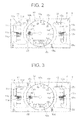
Figs. 2 and 3 , there is shown an exemplaryneedle indicator image 9 displayed on thedot matrix display 8. Theneedle indicator image 9 includes aspeedometer display region 10 for displaying a running speed arranged at a central portion and a firstindicator display region 11 arranged on the left side of thespeedometer display region 10 and which can display, in a switching fashion, an average fuel consumption indicator indicative of average fuel consumption of vehicle and an instant fuel consumption indicator indicative of instant fuel consumption. Theneedle indicator image 9 further includes a secondindicator display region 12 arranged on the right side of thespeedometer display region 10 and which can display, in a switching fashion, a fuel indicator indicative of fuel level of vehicle and a revolution indicator indicative of the number of revolutions of engine. - The
speedometer display region 10 is displayed so as to represent a meter design having a substantially-circular dial 10a indicative of measured amount of the running condition of vehicle. In thespeedometer display region 10, there are displayed aneedle 10b extending from a support point located at a center of the substantially-circular dial 10a. ascale 10c extending in a radial direction of the substantially-circular dial 10a and ascale mark 10d showing a scale value of thescale 10c. For thespeedometer display region 10, thescales 10c and theneedle 10b together constitute an analog speedometer. That is, theneedle 10b is displayed capable of rotating around the support point so that a tip end of theneedle 10b points to the above-described scale to indicate the running speed value of the vehicle. - Furthermore, there is provided an odometer or a trip
meter display region 10e located at a lower portion of thedial 10a to indicate an odometer or a trip meter of the vehicle. - The
speedometer display region 10 includes acolored region 10f which is a predetermined fixed region arranged around a location at which the tip end of theneedle 10b of thedial 10a is located. Thiscolored region 10f is colored with a color different from the rest of the region in thedial 10a. Thecolored region 10f is colored such that a portion at which theneedle 10b is located has a darkest color and the color gradually becomes lighter with increasing distance from the tip end of theneedle 10b (i.e. colored in a gradational fashion). Of course, thiscolored region 10f moves together with the movement of theneedle 10b. - As shown in
Figs. 2 and 3 , the tip end of theneedle 10b is also colored. The color of the tip end of theneedle 10b may be similar to the color of thecolored region 10f and may have the same color strength as the darkest-colored portion of thecolored region 10f. Alternatively, the color of the tip end of theneedle 10b may be different from thecolored region 10f. - In the first
indicator display region 11, there is displayed a meter design having a substantially-rectangular dial 11a and arranged capable of displaying, in a switching fashion, the average fuel consumption indicator and the instant fuel consumption indicator. Furthermore, in the firstindicator display region 11, there are also displayed aneedle 11b extending in a lateral direction of thedial 11a so as to extend over a below-describedscale 11d and being movable along an up-and-down direction of thedial 11a, ascale 11c extending in the lateral direction of thedial 11a and thescale mark 11d indicating a scale value of thescale 11c. - In case of
Fig. 2 , the firstindicator display region 11 is arranged as a meter (i.e. an indicator) which indicates the average fuel consumption value using thescale 11c and theneedle 11b. That is, theneedle 11b is displayed so as to move in the up-and-down direction so theneedle 11b points to thescale 11c to indicate the average fuel consumption value of the vehicle. In case ofFig. 3 , the firstindicator display region 11 is arranged as a meter (i.e. an indicator) which indicates the instant fuel consumption value using the scale I I c and theneedle 11b. That is, theneedle 11b is displayed so as to move in the up-and-down direction so theneedle 11b points to thescale 11c to indicate the instant fuel consumption value of the vehicle. - The first
indicator display region 11 is colored such that acolored region 11e corresponding to a predetermined fixed region located at a lower side of theneedle 11b of thedial 11a is colored with a color different from the rest of the region of thedial 11a. Thecolored region 11e is colored such that a portion at which theneedle 11b is located has a darkest color and the color gradually becomes lighter with increasing distance from theneedle 11b (i.e. colored in a gradational fashion). Of course, thiscolored region 11e moves together with the movement of theneedle 11b. - In addition, in
Figs. 2 and 3 , theneedle 11b is also colored. The color of theneedle 11b may be similar to the color of thecolored region 11e and may have the same color strength as the darkest-colored portion of thecolored region 11e. Alternatively, the color of theneedle 11b may be different from thecolored region 11e. - In the second
indicator display region 12, there is displayed a meter design having a substantially-rectangular dial 12a which is capable of displaying, in a switching fashion, the fuel indicator and the revolution indicator. Furthermore, in the secondindicator display region 12, there are also displayed aneedle 12b extending in a lateral direction of thedial 12a so as to extend over a below-describedscale 12d and being movable along an up-and-down direction of thedial 12a, ascale 12c extending in the lateral direction of thedial 12a and thescale mark 12d indicating a scale value of thescale 12c. - In case of
Fig. 2 , the secondindicator display region 12 is arranged as a meter (i.e. an indicator) which indicates the fuel level value using thescale 12c and theneedle 12b. That is, theneedle 12b is displayed so as to move in the up-and-down direction so theneedle 12b points to thescale 12c to indicate the fuel level value of the vehicle. In case ofFig. 3 , the secondindicator display region 12 is arranged as a meter (i.e. an indicator) which indicates the number of revolutions of engine with thescale 12c and theneedle 12b. That is, theneedle 12b is displayed so as to move in the up-and-down direction so theneedle 12b points to thescale 12c to indicate the number of revolutions of engine of the vehicle. - The second
indicator display region 12 is colored such that acolored region 12e corresponding to a predetermined fixed region located at the lower side of theneedle 12b of thedial 12a is colored with a color different from the rest of the region of thedial 12a. Thecolored region 12e is colored such that a portion at which theneedle 12b is located has a darkest color while the color gradually becomes lighter with increasing distance from theneedle 12b (i.e. colored in a gradational fashion). Of course, thiscolored region 12e moves together with the movement of theneedle 12b. - In addition, in
Figs. 2 and 3 . theneedle 12b is also colored. The color of theneedle 12b may be similar to the color of thecolored region 12e and may have the same color strength as the darkest-colored portion of thecolored region 12e. Alternatively, the color of theneedle 12b may be different from thecolored region 12e. - As described above, the first
indicator display region 11 and the secondindicator display region 12 are arranged in a manner capable of displaying the two kinds of meters by switching the two kinds of meters, i.e. the state shown inFig. 2 and the state shown inFig. 3 . Therefore, thecolored region Fig. 2 and the state shown inFig. 3 . - Next, color change operation of the graphic meter having the above-described arrangement is explained in reference with a flow chart shown in
Fig. 4 . The flow chart shown inFig. 4 is performed by theCPU 1. - Firstly, in step S1, display setting data is obtained and the step proceeds to step S2. The display setting data is information indicative of whether the second
indicator display region 12 is displaying the fuel indicator or the revolution indicator. This information is obtained from information stored in the memory in theCPU 1 or from a signal from an operation switch not shown for manually performing the switching. - Next, in step S2, it is determined whether the display setting is FUEL (i.e. the fuel indicator) or not, and if it is determined as the fuel indicator (i.e. if Y), then the step proceeds to step S3, or if it is determined as not the fuel indicator (i.e. if N), then the step proceeds to step S4.
- Next, in step S3, according to the display setting indicating the fuel indicator, the color setting for the
colored region - In contrast, in step S4, according to the display setting indicating not the fuel indicator, i.e. indicating the revolution indicator, the color setting for the
colored region - In addition, in the flow chart shown in
Fig. 4 , step 52 may perform the determination using information indicating whether the firstindicator display region 11 is displaying the average fuel indicator or the instant fuel indicator, instead of the information indicating whether the secondindicator display region 12 is displaying the fuel indicator or the revolution indicator. Furthermore, the color of the colored region is not limited to blue and orange; however it is preferable to employ the color which allows for clear recognition of the change in the kind of meter displayed in the first indicator display region 11and in the secondindicator display region 12. - According to this embodiment, for the needle indicator image displayed on the
dot matrix display 8 of the graphic meter, there is provided thecolored region needle dial dial 10a. 11a, 12a. Furthermore, thecolored region needle needle needle - Moreover, the color for the
colored regions indicator display region 11 and the secondindicator display region 12. Consequently, the contents of the meter can be determined easily based on the color, allowing it easy to determine the kinds of meters. - In the above-described embodiment, the first
indicator display region 11 and the secondindicator display region 12 include thecolored region needle needle needle lowermost scale colored region colored region needle - Furthermore, the above-described embodiment is arranged so as to switch the two kinds of meters; however there may be three kinds of meters. In this case, obviously the colors used for the
colored region - The embodiments described herein are only representative embodiments of the present invention, and the present invention is not limited to these embodiments. That is, the shown embodiments can be modified or changed in various ways without departing from the scope of the present invention.
-
1 CPU (display control unit) 8 dot matrix display (display unit) 9 needle indicator image 10a dial 10b needle 10f colored region (fixed region located around needle) 11a dial 11b needle 11f colored region (fixed region located around needle) 12a dial 12b needle 12f colored region (fixed region located around needle)
Claims (3)
- A graphic meter device comprising:a display unit for displaying a needle indicator image provided with a dial and a needle pointing to the dial in accordance with a measured quantity; anda display control unit for controlling a display state of the display unit,wherein the display control unit is arranged to display a fixed region located around the needle in the dial such that the fixed region is colored different from the rest of the region in the dial.
- The graphic meter device according to claim 1, wherein the display control unit is arranged to display the fixed region such that the color gradually becomes lighter with increasing distance from the needle.
- The graphic meter device according to claim 1 or 2, wherein the display control unit is capable of switching between a plurality of kinds of needle indicator images displayed on the display unit, and wherein the display control unit is arranged to display the fixed regions of the plurality of kinds of needle indicator images using different colors with respect to each other.
Applications Claiming Priority (2)
| Application Number | Priority Date | Filing Date | Title |
|---|---|---|---|
| JP2010137043A JP5443281B2 (en) | 2010-06-16 | 2010-06-16 | Graphic meter device |
| PCT/JP2011/059059 WO2011158545A1 (en) | 2010-06-16 | 2011-04-12 | Graphic meter device |
Publications (3)
| Publication Number | Publication Date |
|---|---|
| EP2584319A1 true EP2584319A1 (en) | 2013-04-24 |
| EP2584319A4 EP2584319A4 (en) | 2017-05-31 |
| EP2584319B1 EP2584319B1 (en) | 2018-08-22 |
Family
ID=45347957
Family Applications (1)
| Application Number | Title | Priority Date | Filing Date |
|---|---|---|---|
| EP11795453.7A Active EP2584319B1 (en) | 2010-06-16 | 2011-04-12 | Graphic meter device |
Country Status (4)
| Country | Link |
|---|---|
| US (1) | US9466264B2 (en) |
| EP (1) | EP2584319B1 (en) |
| JP (1) | JP5443281B2 (en) |
| WO (1) | WO2011158545A1 (en) |
Families Citing this family (7)
| Publication number | Priority date | Publication date | Assignee | Title |
|---|---|---|---|---|
| JP6109536B2 (en) * | 2012-11-13 | 2017-04-05 | 株式会社ミツトヨ | indicator |
| JP6214508B2 (en) * | 2014-10-10 | 2017-10-18 | 矢崎総業株式会社 | Vehicle display device |
| US9746355B2 (en) * | 2014-11-20 | 2017-08-29 | Leonid Despotuli | Systems and methods for selective contextual illumination of digital information display devices and other information indication devices |
| JP6621998B2 (en) | 2015-04-22 | 2019-12-18 | 矢崎総業株式会社 | Vehicle display device |
| JP2017146167A (en) * | 2016-02-16 | 2017-08-24 | パナソニックIpマネジメント株式会社 | Display device, display method, and display program |
| US11150259B2 (en) * | 2019-12-13 | 2021-10-19 | Honda Motor Co., Ltd. | System and method for display control of gauge graphic |
| US11667195B2 (en) | 2019-12-13 | 2023-06-06 | Honda Motor Co., Ltd. | Display system for a vehicle |
Family Cites Families (9)
| Publication number | Priority date | Publication date | Assignee | Title |
|---|---|---|---|---|
| US4408198A (en) * | 1981-09-14 | 1983-10-04 | Shintron Company, Inc. | Video character generator |
| US4808198A (en) * | 1988-02-01 | 1989-02-28 | Texaco Inc. | Environmentally safe method for disposing of asbestos containing materials |
| JP2000221915A (en) | 1999-01-28 | 2000-08-11 | Kansei Corp | Image displaying method and image displaying device using the method |
| JP3541780B2 (en) * | 2000-04-26 | 2004-07-14 | 株式会社デンソー | Instrument |
| US6718906B2 (en) * | 2002-06-03 | 2004-04-13 | Volvo Trucks North America, Inc. | Dual scale vehicle gauge |
| JP4096910B2 (en) * | 2004-04-20 | 2008-06-04 | 株式会社デンソー | Vehicle instrument |
| US7940604B2 (en) * | 2006-12-21 | 2011-05-10 | Seiko Epson Corporation | Dial indicator display device |
| US20080211652A1 (en) * | 2007-03-02 | 2008-09-04 | Nanolumens Acquisition, Inc. | Dynamic Vehicle Display System |
| JP4293257B2 (en) * | 2007-03-27 | 2009-07-08 | 株式会社デンソー | Display device |
-
2010
- 2010-06-16 JP JP2010137043A patent/JP5443281B2/en active Active
-
2011
- 2011-04-12 WO PCT/JP2011/059059 patent/WO2011158545A1/en active Application Filing
- 2011-04-12 EP EP11795453.7A patent/EP2584319B1/en active Active
- 2011-04-12 US US13/703,976 patent/US9466264B2/en active Active
Non-Patent Citations (1)
| Title |
|---|
| See references of WO2011158545A1 * |
Also Published As
| Publication number | Publication date |
|---|---|
| US9466264B2 (en) | 2016-10-11 |
| WO2011158545A1 (en) | 2011-12-22 |
| JP5443281B2 (en) | 2014-03-19 |
| EP2584319B1 (en) | 2018-08-22 |
| JP2012002629A (en) | 2012-01-05 |
| EP2584319A4 (en) | 2017-05-31 |
| US20130100164A1 (en) | 2013-04-25 |
Similar Documents
| Publication | Publication Date | Title |
|---|---|---|
| US9466264B2 (en) | Graphic meter device | |
| US9463693B2 (en) | Display device | |
| US8339400B2 (en) | Graphic display meter | |
| US8830260B2 (en) | Drawing device of move-target image and display system for vehicle | |
| US10252616B2 (en) | Display device | |
| JP5455828B2 (en) | Instrument graphic display apparatus and method | |
| EP2592377B1 (en) | Measuring instrument | |
| CN103764429A (en) | Image displaying speedometer | |
| US9770948B2 (en) | Display device | |
| JP5185642B2 (en) | Vehicle display device | |
| US10714052B2 (en) | Display device | |
| US10110886B2 (en) | Display device | |
| JP5934485B2 (en) | Meter display device | |
| JP5479051B2 (en) | Vehicle display device | |
| US10181209B2 (en) | Display device for vehicle | |
| JP2011112889A (en) | Display device for vehicle | |
| JP2011059029A (en) | Indicator for vehicle | |
| JP2014119301A (en) | Display device | |
| JP2015141039A (en) | Pointer-indicated value calculating method | |
| JP2012111355A (en) | Display device for vehicle | |
| JP6220151B2 (en) | Display device | |
| JP2009018642A (en) | Display device for vehicle | |
| JP2011195003A (en) | Display device for vehicle | |
| JP2011112888A (en) | Display device for vehicle |
Legal Events
| Date | Code | Title | Description |
|---|---|---|---|
| PUAI | Public reference made under article 153(3) epc to a published international application that has entered the european phase |
Free format text: ORIGINAL CODE: 0009012 |
|
| 17P | Request for examination filed |
Effective date: 20130116 |
|
| AK | Designated contracting states |
Kind code of ref document: A1 Designated state(s): AL AT BE BG CH CY CZ DE DK EE ES FI FR GB GR HR HU IE IS IT LI LT LU LV MC MK MT NL NO PL PT RO RS SE SI SK SM TR |
|
| DAX | Request for extension of the european patent (deleted) | ||
| RA4 | Supplementary search report drawn up and despatched (corrected) |
Effective date: 20170502 |
|
| RIC1 | Information provided on ipc code assigned before grant |
Ipc: G09F 9/00 20060101ALI20170424BHEP Ipc: G01D 7/00 20060101AFI20170424BHEP Ipc: B60K 35/00 20060101ALI20170424BHEP |
|
| GRAP | Despatch of communication of intention to grant a patent |
Free format text: ORIGINAL CODE: EPIDOSNIGR1 |
|
| STAA | Information on the status of an ep patent application or granted ep patent |
Free format text: STATUS: GRANT OF PATENT IS INTENDED |
|
| INTG | Intention to grant announced |
Effective date: 20180517 |
|
| GRAS | Grant fee paid |
Free format text: ORIGINAL CODE: EPIDOSNIGR3 |
|
| GRAA | (expected) grant |
Free format text: ORIGINAL CODE: 0009210 |
|
| STAA | Information on the status of an ep patent application or granted ep patent |
Free format text: STATUS: THE PATENT HAS BEEN GRANTED |
|
| AK | Designated contracting states |
Kind code of ref document: B1 Designated state(s): AL AT BE BG CH CY CZ DE DK EE ES FI FR GB GR HR HU IE IS IT LI LT LU LV MC MK MT NL NO PL PT RO RS SE SI SK SM TR |
|
| REG | Reference to a national code |
Ref country code: GB Ref legal event code: FG4D |
|
| REG | Reference to a national code |
Ref country code: CH Ref legal event code: EP |
|
| REG | Reference to a national code |
Ref country code: DE Ref legal event code: R096 Ref document number: 602011051355 Country of ref document: DE |
|
| REG | Reference to a national code |
Ref country code: AT Ref legal event code: REF Ref document number: 1033037 Country of ref document: AT Kind code of ref document: T Effective date: 20180915 |
|
| REG | Reference to a national code |
Ref country code: IE Ref legal event code: FG4D |
|
| REG | Reference to a national code |
Ref country code: NL Ref legal event code: MP Effective date: 20180822 |
|
| REG | Reference to a national code |
Ref country code: LT Ref legal event code: MG4D |
|
| PG25 | Lapsed in a contracting state [announced via postgrant information from national office to epo] |
Ref country code: LT Free format text: LAPSE BECAUSE OF FAILURE TO SUBMIT A TRANSLATION OF THE DESCRIPTION OR TO PAY THE FEE WITHIN THE PRESCRIBED TIME-LIMIT Effective date: 20180822 Ref country code: RS Free format text: LAPSE BECAUSE OF FAILURE TO SUBMIT A TRANSLATION OF THE DESCRIPTION OR TO PAY THE FEE WITHIN THE PRESCRIBED TIME-LIMIT Effective date: 20180822 Ref country code: IS Free format text: LAPSE BECAUSE OF FAILURE TO SUBMIT A TRANSLATION OF THE DESCRIPTION OR TO PAY THE FEE WITHIN THE PRESCRIBED TIME-LIMIT Effective date: 20181222 Ref country code: GR Free format text: LAPSE BECAUSE OF FAILURE TO SUBMIT A TRANSLATION OF THE DESCRIPTION OR TO PAY THE FEE WITHIN THE PRESCRIBED TIME-LIMIT Effective date: 20181123 Ref country code: NO Free format text: LAPSE BECAUSE OF FAILURE TO SUBMIT A TRANSLATION OF THE DESCRIPTION OR TO PAY THE FEE WITHIN THE PRESCRIBED TIME-LIMIT Effective date: 20181122 Ref country code: SE Free format text: LAPSE BECAUSE OF FAILURE TO SUBMIT A TRANSLATION OF THE DESCRIPTION OR TO PAY THE FEE WITHIN THE PRESCRIBED TIME-LIMIT Effective date: 20180822 Ref country code: FI Free format text: LAPSE BECAUSE OF FAILURE TO SUBMIT A TRANSLATION OF THE DESCRIPTION OR TO PAY THE FEE WITHIN THE PRESCRIBED TIME-LIMIT Effective date: 20180822 Ref country code: BG Free format text: LAPSE BECAUSE OF FAILURE TO SUBMIT A TRANSLATION OF THE DESCRIPTION OR TO PAY THE FEE WITHIN THE PRESCRIBED TIME-LIMIT Effective date: 20181122 Ref country code: NL Free format text: LAPSE BECAUSE OF FAILURE TO SUBMIT A TRANSLATION OF THE DESCRIPTION OR TO PAY THE FEE WITHIN THE PRESCRIBED TIME-LIMIT Effective date: 20180822 |
|
| REG | Reference to a national code |
Ref country code: AT Ref legal event code: MK05 Ref document number: 1033037 Country of ref document: AT Kind code of ref document: T Effective date: 20180822 |
|
| PG25 | Lapsed in a contracting state [announced via postgrant information from national office to epo] |
Ref country code: HR Free format text: LAPSE BECAUSE OF FAILURE TO SUBMIT A TRANSLATION OF THE DESCRIPTION OR TO PAY THE FEE WITHIN THE PRESCRIBED TIME-LIMIT Effective date: 20180822 Ref country code: AL Free format text: LAPSE BECAUSE OF FAILURE TO SUBMIT A TRANSLATION OF THE DESCRIPTION OR TO PAY THE FEE WITHIN THE PRESCRIBED TIME-LIMIT Effective date: 20180822 Ref country code: LV Free format text: LAPSE BECAUSE OF FAILURE TO SUBMIT A TRANSLATION OF THE DESCRIPTION OR TO PAY THE FEE WITHIN THE PRESCRIBED TIME-LIMIT Effective date: 20180822 |
|
| PG25 | Lapsed in a contracting state [announced via postgrant information from national office to epo] |
Ref country code: CZ Free format text: LAPSE BECAUSE OF FAILURE TO SUBMIT A TRANSLATION OF THE DESCRIPTION OR TO PAY THE FEE WITHIN THE PRESCRIBED TIME-LIMIT Effective date: 20180822 Ref country code: RO Free format text: LAPSE BECAUSE OF FAILURE TO SUBMIT A TRANSLATION OF THE DESCRIPTION OR TO PAY THE FEE WITHIN THE PRESCRIBED TIME-LIMIT Effective date: 20180822 Ref country code: IT Free format text: LAPSE BECAUSE OF FAILURE TO SUBMIT A TRANSLATION OF THE DESCRIPTION OR TO PAY THE FEE WITHIN THE PRESCRIBED TIME-LIMIT Effective date: 20180822 Ref country code: PL Free format text: LAPSE BECAUSE OF FAILURE TO SUBMIT A TRANSLATION OF THE DESCRIPTION OR TO PAY THE FEE WITHIN THE PRESCRIBED TIME-LIMIT Effective date: 20180822 Ref country code: ES Free format text: LAPSE BECAUSE OF FAILURE TO SUBMIT A TRANSLATION OF THE DESCRIPTION OR TO PAY THE FEE WITHIN THE PRESCRIBED TIME-LIMIT Effective date: 20180822 Ref country code: AT Free format text: LAPSE BECAUSE OF FAILURE TO SUBMIT A TRANSLATION OF THE DESCRIPTION OR TO PAY THE FEE WITHIN THE PRESCRIBED TIME-LIMIT Effective date: 20180822 Ref country code: EE Free format text: LAPSE BECAUSE OF FAILURE TO SUBMIT A TRANSLATION OF THE DESCRIPTION OR TO PAY THE FEE WITHIN THE PRESCRIBED TIME-LIMIT Effective date: 20180822 |
|
| REG | Reference to a national code |
Ref country code: DE Ref legal event code: R097 Ref document number: 602011051355 Country of ref document: DE |
|
| PG25 | Lapsed in a contracting state [announced via postgrant information from national office to epo] |
Ref country code: DK Free format text: LAPSE BECAUSE OF FAILURE TO SUBMIT A TRANSLATION OF THE DESCRIPTION OR TO PAY THE FEE WITHIN THE PRESCRIBED TIME-LIMIT Effective date: 20180822 Ref country code: SM Free format text: LAPSE BECAUSE OF FAILURE TO SUBMIT A TRANSLATION OF THE DESCRIPTION OR TO PAY THE FEE WITHIN THE PRESCRIBED TIME-LIMIT Effective date: 20180822 Ref country code: SK Free format text: LAPSE BECAUSE OF FAILURE TO SUBMIT A TRANSLATION OF THE DESCRIPTION OR TO PAY THE FEE WITHIN THE PRESCRIBED TIME-LIMIT Effective date: 20180822 |
|
| PLBE | No opposition filed within time limit |
Free format text: ORIGINAL CODE: 0009261 |
|
| STAA | Information on the status of an ep patent application or granted ep patent |
Free format text: STATUS: NO OPPOSITION FILED WITHIN TIME LIMIT |
|
| 26N | No opposition filed |
Effective date: 20190523 |
|
| PG25 | Lapsed in a contracting state [announced via postgrant information from national office to epo] |
Ref country code: SI Free format text: LAPSE BECAUSE OF FAILURE TO SUBMIT A TRANSLATION OF THE DESCRIPTION OR TO PAY THE FEE WITHIN THE PRESCRIBED TIME-LIMIT Effective date: 20180822 |
|
| REG | Reference to a national code |
Ref country code: CH Ref legal event code: PL |
|
| REG | Reference to a national code |
Ref country code: BE Ref legal event code: MM Effective date: 20190430 |
|
| GBPC | Gb: european patent ceased through non-payment of renewal fee |
Effective date: 20190412 |
|
| PG25 | Lapsed in a contracting state [announced via postgrant information from national office to epo] |
Ref country code: LU Free format text: LAPSE BECAUSE OF NON-PAYMENT OF DUE FEES Effective date: 20190412 Ref country code: MC Free format text: LAPSE BECAUSE OF FAILURE TO SUBMIT A TRANSLATION OF THE DESCRIPTION OR TO PAY THE FEE WITHIN THE PRESCRIBED TIME-LIMIT Effective date: 20180822 |
|
| PG25 | Lapsed in a contracting state [announced via postgrant information from national office to epo] |
Ref country code: LI Free format text: LAPSE BECAUSE OF NON-PAYMENT OF DUE FEES Effective date: 20190430 Ref country code: CH Free format text: LAPSE BECAUSE OF NON-PAYMENT OF DUE FEES Effective date: 20190430 Ref country code: GB Free format text: LAPSE BECAUSE OF NON-PAYMENT OF DUE FEES Effective date: 20190412 |
|
| PG25 | Lapsed in a contracting state [announced via postgrant information from national office to epo] |
Ref country code: BE Free format text: LAPSE BECAUSE OF NON-PAYMENT OF DUE FEES Effective date: 20190430 |
|
| PG25 | Lapsed in a contracting state [announced via postgrant information from national office to epo] |
Ref country code: TR Free format text: LAPSE BECAUSE OF FAILURE TO SUBMIT A TRANSLATION OF THE DESCRIPTION OR TO PAY THE FEE WITHIN THE PRESCRIBED TIME-LIMIT Effective date: 20180822 |
|
| PG25 | Lapsed in a contracting state [announced via postgrant information from national office to epo] |
Ref country code: IE Free format text: LAPSE BECAUSE OF NON-PAYMENT OF DUE FEES Effective date: 20190412 |
|
| PG25 | Lapsed in a contracting state [announced via postgrant information from national office to epo] |
Ref country code: FR Free format text: LAPSE BECAUSE OF NON-PAYMENT OF DUE FEES Effective date: 20190430 Ref country code: PT Free format text: LAPSE BECAUSE OF FAILURE TO SUBMIT A TRANSLATION OF THE DESCRIPTION OR TO PAY THE FEE WITHIN THE PRESCRIBED TIME-LIMIT Effective date: 20181222 |
|
| PG25 | Lapsed in a contracting state [announced via postgrant information from national office to epo] |
Ref country code: CY Free format text: LAPSE BECAUSE OF FAILURE TO SUBMIT A TRANSLATION OF THE DESCRIPTION OR TO PAY THE FEE WITHIN THE PRESCRIBED TIME-LIMIT Effective date: 20180822 |
|
| PG25 | Lapsed in a contracting state [announced via postgrant information from national office to epo] |
Ref country code: MT Free format text: LAPSE BECAUSE OF FAILURE TO SUBMIT A TRANSLATION OF THE DESCRIPTION OR TO PAY THE FEE WITHIN THE PRESCRIBED TIME-LIMIT Effective date: 20180822 Ref country code: HU Free format text: LAPSE BECAUSE OF FAILURE TO SUBMIT A TRANSLATION OF THE DESCRIPTION OR TO PAY THE FEE WITHIN THE PRESCRIBED TIME-LIMIT; INVALID AB INITIO Effective date: 20110412 |
|
| PG25 | Lapsed in a contracting state [announced via postgrant information from national office to epo] |
Ref country code: MK Free format text: LAPSE BECAUSE OF FAILURE TO SUBMIT A TRANSLATION OF THE DESCRIPTION OR TO PAY THE FEE WITHIN THE PRESCRIBED TIME-LIMIT Effective date: 20180822 |
|
| PGFP | Annual fee paid to national office [announced via postgrant information from national office to epo] |
Ref country code: DE Payment date: 20230228 Year of fee payment: 13 |