EP2584276A2 - Outdoor unit of air-conditioning apparatus - Google Patents
Outdoor unit of air-conditioning apparatus Download PDFInfo
- Publication number
- EP2584276A2 EP2584276A2 EP12182869.3A EP12182869A EP2584276A2 EP 2584276 A2 EP2584276 A2 EP 2584276A2 EP 12182869 A EP12182869 A EP 12182869A EP 2584276 A2 EP2584276 A2 EP 2584276A2
- Authority
- EP
- European Patent Office
- Prior art keywords
- housing
- end portion
- panel
- heat exchanger
- side panel
- Prior art date
- Legal status (The legal status is an assumption and is not a legal conclusion. Google has not performed a legal analysis and makes no representation as to the accuracy of the status listed.)
- Granted
Links
Images



Classifications
-
- F—MECHANICAL ENGINEERING; LIGHTING; HEATING; WEAPONS; BLASTING
- F24—HEATING; RANGES; VENTILATING
- F24F—AIR-CONDITIONING; AIR-HUMIDIFICATION; VENTILATION; USE OF AIR CURRENTS FOR SCREENING
- F24F1/00—Room units for air-conditioning, e.g. separate or self-contained units or units receiving primary air from a central station
- F24F1/06—Separate outdoor units, e.g. outdoor unit to be linked to a separate room comprising a compressor and a heat exchanger
- F24F1/14—Heat exchangers specially adapted for separate outdoor units
- F24F1/16—Arrangement or mounting thereof
-
- F—MECHANICAL ENGINEERING; LIGHTING; HEATING; WEAPONS; BLASTING
- F24—HEATING; RANGES; VENTILATING
- F24F—AIR-CONDITIONING; AIR-HUMIDIFICATION; VENTILATION; USE OF AIR CURRENTS FOR SCREENING
- F24F1/00—Room units for air-conditioning, e.g. separate or self-contained units or units receiving primary air from a central station
- F24F1/06—Separate outdoor units, e.g. outdoor unit to be linked to a separate room comprising a compressor and a heat exchanger
- F24F1/46—Component arrangements in separate outdoor units
-
- F—MECHANICAL ENGINEERING; LIGHTING; HEATING; WEAPONS; BLASTING
- F24—HEATING; RANGES; VENTILATING
- F24F—AIR-CONDITIONING; AIR-HUMIDIFICATION; VENTILATION; USE OF AIR CURRENTS FOR SCREENING
- F24F1/00—Room units for air-conditioning, e.g. separate or self-contained units or units receiving primary air from a central station
- F24F1/06—Separate outdoor units, e.g. outdoor unit to be linked to a separate room comprising a compressor and a heat exchanger
- F24F1/56—Casing or covers of separate outdoor units, e.g. fan guards
Definitions
- the present invention relates to an outdoor unit of an air-conditioning apparatus.
- an outdoor unit of such a separate-type air-conditioning apparatus includes a heat exchanger formed into an L-shape to fit the housing.
- a heat exchanger formed into an L-shape to fit the housing.
- a raised piece on the left side of the housing of the outdoor unit is engaged with a notch in an end plate at the front of an L-shaped heat exchanger, and thus the heat exchanger is secured on the left side of the housing (see, e.g., Patent Literature 1).
- An outdoor unit described in Patent Literature 1 has a configuration in which a raised piece on the left side of the housing of the outdoor unit is engaged with a notch in an end plate at the front of an L-shaped heat exchanger, and thus the heat exchanger is secured on the left side of the housing.
- the left side of the housing needs to have, for example, a circular hole for securing the end plate of the heat exchanger. Since this requires an area for forming the circular hole on the left side of the housing, it is difficult to provide ventilation slots in the vicinity of this area. In the entire area of the left side of the housing, an area available for forming ventilation slots (air inlets) is limited. This results in degradation of heat exchange efficiency.
- An object of the present invention is to provide an outdoor unit of an air-conditioning apparatus, which includes a heat exchanger having high heat exchange efficiency.
- An outdoor unit of an air-conditioning apparatus includes a housing having a substantially rectangular parallelepiped shape; at least one heat exchanger formed into a substantially L-shape, the heat exchanger being disposed along the inside of one side of the housing and along the inside of the rear of the housing; and a securing member configured to secure the heat exchanger to the housing.
- the housing includes a side panel configured to form the one side of the housing and to partially extend to the front of the housing, and a front panel configured to form the front of the housing together with the part of the side panel. An end portion of the front panel is connected, at the front of the housing, to an end portion of the side panel.
- the side panel is provided with a plurality of air inlets in an area that forms the one side of the housing.
- the securing member is interposed between a front end portion of the heat exchanger and the connection between the end portion of the front panel and the end portion of the side panel, and thereby secures the heat exchanger to the front panel.
- an end portion of the front panel is connected, at the front of the housing, to an end portion of the side panel.
- the securing member is interposed between a front end portion of the heat exchanger and the connection between the end portion of the front panel and the end portion of the side panel, and thereby secures the heat exchanger to the front panel. Therefore, it is possible to provide a larger area for air inlets in the side panel and achieve higher heat exchange efficiency than before.
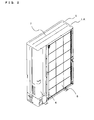
- Fig. 1 is a perspective view of an outdoor unit of an air-conditioning apparatus according to Embodiment 1 of the present invention, as viewed from the front left of the outdoor unit.
- Fig. 2 is a perspective view of the outdoor unit of the air-conditioning apparatus according to Embodiment 1 of the present invention, as viewed from the rear left of the outdoor unit.
- a housing 1A of an outdoor unit 1 includes a front left panel 2, a front right panel 3, a left side panel 4, a rear left panel 5, a rear right panel 6, a top panel 7, and a bottom panel (not shown).
- the left side panel 4 forms a left side of the housing 1A and extends partially to the front of the housing 1A.
- the front left panel 2 forms the front of the housing 1A together with the part of the left side panel 4. An end portion of the front left panel 2 is connected, at the front of the housing 1A, to an end portion of the left side panel 4 (described in detail below with reference to Fig. 3 ).
- the left side panel 4 is provided with a plurality of air inlets 11a in an area that forms the left side of the housing 1A.
- the rear left panel 5 and the rear right panel 6 form the rear of the housing 1A.
- the rear right panel 6 forms a part of the rear of the housing 1A and a right side of the housing 1A.
- Fig. 3 is a plan view of a housing according to Embodiment 1 of the present invention, with a top panel of the housing removed.
- the housing 1A includes a heat exchanger 12a and a heat exchanger 12b.
- the heat exchangers 12a and 12b are formed into a substantially L-shape and disposed along the rear and the left side of the housing 1A.
- the heat exchangers 12a and 12b are secured to each other, for example, with a band.
- An end portion of the heat exchanger 12b (adjacent to the front of the housing 1A) is located closer to the front of the housing 1A than an end portion of the heat exchanger 12a (adjacent to the front of the housing 1A) is.
- the heat exchanger 12b is secured to the front left panel 2, with a metal sheet 13 interposed therebetween.
- the metal sheet 13 has a first end portion 13a adjacent to the front of the housing 1A, and a second end portion 13b adjacent to the rear of the housing 1A.
- the first end portion 13a is secured at the front of the housing 1A.
- the second end portion 13b is secured at the end portion of the heat exchanger 12b (adjacent to the front of the housing 1A).
- a first position 15 is a position at which the end portion of the left side panel 4 (i.e., the end portion forming a part of the front of the housing 1A) is connected to the end portion of the front left panel 2 (i.e., the end portion adjacent to the left side of the housing 1A).
- a second position 16 is a position at which the first end portion 13a is secured at the front of the housing 1A.
- the first position 15 and the second position 16 substantially coincide in plan view but differ in height. Note that the end portion of the left side panel 4 and the end portion of the front left panel 2 overlap and are connected to each other in their overlapping region.
- Fig. 4 is a plan view of a housing according to a modification of Embodiment 1 of the present invention illustrated in Fig. 3 , with a top panel of the housing removed.
- a heat exchanger 12c is added to the heat exchangers 12a and 12b illustrated in Fig. 3 .
- the heat exchanger 12c is disposed inside the heat exchanger 12b.
- An end portion of the heat exchanger 12c (adjacent to the front of the housing 1A) is closer to the front of the housing 1A than the end portion of the heat exchanger 12b (adjacent to the front of the housing 1A) is.
- Fig. 4 is a plan view of a housing according to a modification of Embodiment 1 of the present invention illustrated in Fig. 3 , with a top panel of the housing removed.
- a heat exchanger 12c is added to the heat exchangers 12a and 12b illustrated in Fig. 3 .
- the heat exchanger 12c is disposed inside the heat exchanger 12b
- a metal sheet 14 for securing the heat exchanger 12c differs in shape from the metal sheet 13 illustrated in Fig. 3 .
- the heat exchanger 12b is secured to the second end portion 13b of the metal sheet 13 in Fig. 3
- the heat exchanger 12c is secured to a second end portion 14b of the metal sheet 14 in Fig. 4 .
- a first end portion 14a of the metal sheet 14 in Fig. 4 is secured at the second position 16, that is, at the same position as the first end portion 13a of the metal sheet 13 in Fig. 3 .
- the front left panel 2 is connected to the left side panel 4 at the first position 15 at the front of the housing 1A.
- the first end portion 13a (or first end portion 14a) secures the heat exchanger 12b (or heat exchanger 12c) to the front left panel 2 at the second position 16 that coincides with the first position 15 in plan view. That is, the heat exchanger 12b (or heat exchanger 12c) is secured, not on the left side of the housing 1A, but at the point of connection at the front of the housing 1A. Thus, since there are no components etc.
- the heat exchanger 12b (or heat exchanger 12c) is configured to be secured at the front of the housing 1A, it is possible to extend the heat exchanger 12b (or heat exchanger 12c) to the front of the outdoor unit 1 and increase the efficiency of heat exchange of the heat exchangers 12a, 12b, and 12c with air drawn through the air inlets 11a in the left side panel 4 into the housing 1A.
- any number of heat exchangers can be secured at the same position at the front of the housing 1A by varying the shape of the metal sheet 13 (or metal sheet 14). That is, the housing 1A with the same shape can be used regardless of the number of heat exchangers included in the housing 1A.
- the housing 1A includes two or three heat exchangers in Embodiment 1 of the present invention, the number of heat exchangers is not limited to this.
- Embodiment 1 of the present invention describes the metal sheet 13 (or metal sheet 14) as a securing member of the present invention, the shape of the securing member is not limited to this, and may be modified as necessary.
- the left side panel 4 forms the left side of the housing 1A and partially extends to the front of the housing 1A.
- the present invention is not limited to this.
- the left side panel 4 may be formed into a substantially U-shape such that it forms the left side of the housing 1A, partially extends to the front of the housing 1A, and forms at least a part of the rear of the housing 1A. This can reduce the number of components and simplify the assembly process.
- the air inlets 11a have the shape illustrated in Fig. 1 .
- the shape of the air inlets 11a is not limited to this and may be determined appropriately.
- the front end portions of air inlets 11a closest to the front of the housing 1A may be closer to the front of the housing 1A, in side view, than the end portion of the heat exchanger 12b (or heat exchanger 12c) adjacent to the front of the housing 1A is. With this configuration, it is possible to further increase the heat exchange efficiency of the heat exchangers 12a, 12b, and 12c.
- Fig. 5 is a perspective view of an outdoor unit of an air-conditioning apparatus according to Embodiment 2 of the present invention, as viewed from the front left of the outdoor unit.
- Embodiment 2 unlike in Embodiment 1, there are a left-side front panel 8 and a left-side rear panel 9 spaced apart on the left side of the housing 1A.
- the left-side front panel 8 corresponds to a first side panel of the present invention
- the left-side rear panel 9 corresponds to a second side panel of the present invention.
- the left-side front panel 8 forms a part of the left side of the housing 1A and partially extends to the front of the housing 1A.
- the left-side rear panel 9 is disposed closer to the rear of the housing 1A than the left-side front panel 8 is, and forms a part of the left side of the housing 1A.
- the end portion of the front left panel 2 is connected at the front of the housing 1A to an end portion of the left-side front panel 8, in the same manner as that in the example illustrated in Fig. 4 .
- Each of the left-side front panel 8 and the left-side rear panel 9 is provided with a plurality of air inlets 11a. There is an opening between the left-side front panel 8 and the left-side rear panel 9. This opening serves as an air inlet 11b.
- Fig. 6 is a plan view of the outdoor unit 1 of Fig. 5 , with a top panel removed.
- the left side of the housing 1A in Fig. 4 is formed by the left side panel 4
- the left side of the housing 1A in Fig. 6 is formed by two components, the left-side front panel 8 and the left-side rear panel 9.
- the other configurations illustrated in Fig. 6 are the same as those illustrated in Fig. 4 .
- the left-side front panel 8 and the left-side rear panel 9 are disposed on the left side of the housing 1A.
- Each of the left-side front panel 8 and the left-side rear panel 9 is provided with air inlets 11a.
- 1 outdoor unit
- 1A housing
- 2 front left panel
- 3 front right panel
- 4 left side panel
- 5 rear left panel
- 6 rear right panel
- 7 top panel
- 8 left-side front panel
- 9 left-side rear panel
- 11a, 11b air inlet
- 12a, 12b, 12c heat exchanger
- 13a, 14a metal sheet
- 13a, 14a first end portion
- 13b, 14b second end portion
- 16 second position
Landscapes
- Engineering & Computer Science (AREA)
- Chemical & Material Sciences (AREA)
- Combustion & Propulsion (AREA)
- Mechanical Engineering (AREA)
- General Engineering & Computer Science (AREA)
- Other Air-Conditioning Systems (AREA)
- Air Filters, Heat-Exchange Apparatuses, And Housings Of Air-Conditioning Units (AREA)
Abstract
Description
- The present invention relates to an outdoor unit of an air-conditioning apparatus.
- In recent years, high-performance and high-capacity separate-type air-conditioning apparatuses have become widespread significantly. For effective use of installation space, an outdoor unit of such a separate-type air-conditioning apparatus includes a heat exchanger formed into an L-shape to fit the housing.
Conventionally, in an outdoor unit of this type, for example, a raised piece on the left side of the housing of the outdoor unit is engaged with a notch in an end plate at the front of an L-shaped heat exchanger, and thus the heat exchanger is secured on the left side of the housing (see, e.g., Patent Literature 1). -
- [Patent Literature 1] Japanese Unexamined Utility Model Registration Application Publication No.
5-3822 Fig. 2 ) - An outdoor unit described in
Patent Literature 1 has a configuration in which a raised piece on the left side of the housing of the outdoor unit is engaged with a notch in an end plate at the front of an L-shaped heat exchanger, and thus the heat exchanger is secured on the left side of the housing. In this configuration, the left side of the housing needs to have, for example, a circular hole for securing the end plate of the heat exchanger. Since this requires an area for forming the circular hole on the left side of the housing, it is difficult to provide ventilation slots in the vicinity of this area. In the entire area of the left side of the housing, an area available for forming ventilation slots (air inlets) is limited. This results in degradation of heat exchange efficiency. - The present invention has been made to solve the problems describe above. An object of the present invention is to provide an outdoor unit of an air-conditioning apparatus, which includes a heat exchanger having high heat exchange efficiency.
- An outdoor unit of an air-conditioning apparatus according to the present invention includes a housing having a substantially rectangular parallelepiped shape; at least one heat exchanger formed into a substantially L-shape, the heat exchanger being disposed along the inside of one side of the housing and along the inside of the rear of the housing; and a securing member configured to secure the heat exchanger to the housing. The housing includes a side panel configured to form the one side of the housing and to partially extend to the front of the housing, and a front panel configured to form the front of the housing together with the part of the side panel. An end portion of the front panel is connected, at the front of the housing, to an end portion of the side panel. The side panel is provided with a plurality of air inlets in an area that forms the one side of the housing. The securing member is interposed between a front end portion of the heat exchanger and the connection between the end portion of the front panel and the end portion of the side panel, and thereby secures the heat exchanger to the front panel.
- In the outdoor unit of the air-conditioning apparatus according to the present invention, an end portion of the front panel is connected, at the front of the housing, to an end portion of the side panel. The securing member is interposed between a front end portion of the heat exchanger and the connection between the end portion of the front panel and the end portion of the side panel, and thereby secures the heat exchanger to the front panel. Therefore, it is possible to provide a larger area for air inlets in the side panel and achieve higher heat exchange efficiency than before.
-
- [
Fig. 1] Fig. 1 is a perspective view of an outdoor unit of an air-conditioning apparatus according toEmbodiment 1 of the present invention, as viewed from the front left of the outdoor unit. - [
Fig. 2] Fig. 2 is a perspective view of the outdoor unit of the air-conditioning apparatus according toEmbodiment 1 of the present invention, as viewed from the rear left of the outdoor unit. - [
Fig. 3] Fig. 3 is a plan view of a housing according toEmbodiment 1 of the present invention, with a top panel of the housing removed. - [
Fig. 4] Fig. 4 is a plan view of a housing according to a modification ofEmbodiment 1 of the present invention illustrated inFig. 3 , with a top panel of the housing removed. - [
Fig. 5] Fig. 5 is a perspective view of an outdoor unit of an air-conditioning apparatus according toEmbodiment 2 of the present invention, as viewed from the front left of the outdoor unit. - [
Fig. 6] Fig. 6 is a plan view of a housing according toEmbodiment 2 of the present invention, with a top panel of the housing removed. -
Fig. 1 is a perspective view of an outdoor unit of an air-conditioning apparatus according toEmbodiment 1 of the present invention, as viewed from the front left of the outdoor unit.Fig. 2 is a perspective view of the outdoor unit of the air-conditioning apparatus according toEmbodiment 1 of the present invention, as viewed from the rear left of the outdoor unit.
As illustrated inFig. 1 andFig. 2 , a housing 1A of anoutdoor unit 1 includes a frontleft panel 2, a frontright panel 3, aleft side panel 4, a rearleft panel 5, a rearright panel 6, atop panel 7, and a bottom panel (not shown).
Theleft side panel 4 forms a left side of the housing 1A and extends partially to the front of the housing 1A. The frontleft panel 2 forms the front of the housing 1A together with the part of theleft side panel 4. An end portion of the frontleft panel 2 is connected, at the front of the housing 1A, to an end portion of the left side panel 4 (described in detail below with reference toFig. 3 ). Theleft side panel 4 is provided with a plurality of air inlets 11a in an area that forms the left side of the housing 1A. The rearleft panel 5 and the rearright panel 6 form the rear of the housing 1A. The rearright panel 6 forms a part of the rear of the housing 1A and a right side of the housing 1A. -
Fig. 3 is a plan view of a housing according to Embodiment 1 of the present invention, with a top panel of the housing removed.
As illustrated inFig. 3 , the housing 1A includes aheat exchanger 12a and aheat exchanger 12b. Theheat exchangers heat exchangers heat exchanger 12b (adjacent to the front of the housing 1A) is located closer to the front of the housing 1A than an end portion of theheat exchanger 12a (adjacent to the front of the housing 1A) is.
Theheat exchanger 12b is secured to the frontleft panel 2, with a metal sheet 13 interposed therebetween. The metal sheet 13 has a first end portion 13a adjacent to the front of the housing 1A, and asecond end portion 13b adjacent to the rear of the housing 1A. The first end portion 13a is secured at the front of the housing 1A. Thesecond end portion 13b is secured at the end portion of theheat exchanger 12b (adjacent to the front of the housing 1A).
A first position 15 is a position at which the end portion of the left side panel 4 (i.e., the end portion forming a part of the front of the housing 1A) is connected to the end portion of the front left panel 2 (i.e., the end portion adjacent to the left side of the housing 1A). A second position 16 is a position at which the first end portion 13a is secured at the front of the housing 1A. The first position 15 and the second position 16 substantially coincide in plan view but differ in height. Note that the end portion of theleft side panel 4 and the end portion of the frontleft panel 2 overlap and are connected to each other in their overlapping region. -
Fig. 4 is a plan view of a housing according to a modification ofEmbodiment 1 of the present invention illustrated inFig. 3 , with a top panel of the housing removed.
In the housing 1A illustrated inFig. 4 , aheat exchanger 12c is added to theheat exchangers Fig. 3 . As illustrated, theheat exchanger 12c is disposed inside theheat exchanger 12b. An end portion of theheat exchanger 12c (adjacent to the front of the housing 1A) is closer to the front of the housing 1A than the end portion of theheat exchanger 12b (adjacent to the front of the housing 1A) is.
As illustrated inFig. 4 , ametal sheet 14 for securing theheat exchanger 12c differs in shape from the metal sheet 13 illustrated inFig. 3 . Theheat exchanger 12b is secured to thesecond end portion 13b of the metal sheet 13 inFig. 3 , whereas theheat exchanger 12c is secured to a second end portion 14b of themetal sheet 14 inFig. 4 . A first end portion 14a of themetal sheet 14 inFig. 4 is secured at the second position 16, that is, at the same position as the first end portion 13a of the metal sheet 13 inFig. 3 . - As described above, in the
outdoor unit 1 of the air-conditioning apparatus according toEmbodiment 1, the frontleft panel 2 is connected to theleft side panel 4 at the first position 15 at the front of the housing 1A. The first end portion 13a (or first end portion 14a) secures theheat exchanger 12b (orheat exchanger 12c) to the frontleft panel 2 at the second position 16 that coincides with the first position 15 in plan view. That is, theheat exchanger 12b (orheat exchanger 12c) is secured, not on the left side of the housing 1A, but at the point of connection at the front of the housing 1A. Thus, since there are no components etc. that may prevent formation of the air inlets 11a in theleft side panel 4, it is possible to provide a larger area for forming air inlets and achieve higher heat exchange efficiency than before. Additionally, since theheat exchanger 12b (orheat exchanger 12c) is configured to be secured at the front of the housing 1A, it is possible to extend theheat exchanger 12b (orheat exchanger 12c) to the front of theoutdoor unit 1 and increase the efficiency of heat exchange of theheat exchangers left side panel 4 into the housing 1A. - In the
outdoor unit 1 of the air-conditioning apparatus according toEmbodiment 1 of the present invention, any number of heat exchangers can be secured at the same position at the front of the housing 1A by varying the shape of the metal sheet 13 (or metal sheet 14). That is, the housing 1A with the same shape can be used regardless of the number of heat exchangers included in the housing 1A. - Although the housing 1A includes two or three heat exchangers in
Embodiment 1 of the present invention, the number of heat exchangers is not limited to this. - Although
Embodiment 1 of the present invention describes the metal sheet 13 (or metal sheet 14) as a securing member of the present invention, the shape of the securing member is not limited to this, and may be modified as necessary. - In
Embodiment 1 of the present invention, theleft side panel 4 forms the left side of the housing 1A and partially extends to the front of the housing 1A. However, the present invention is not limited to this. For example, theleft side panel 4 may be formed into a substantially U-shape such that it forms the left side of the housing 1A, partially extends to the front of the housing 1A, and forms at least a part of the rear of the housing 1A. This can reduce the number of components and simplify the assembly process. - In
Embodiment 1 of the present invention, the air inlets 11a have the shape illustrated inFig. 1 . However, the shape of the air inlets 11a is not limited to this and may be determined appropriately. - In
Embodiment 1 of the present invention, the front end portions of air inlets 11a closest to the front of the housing 1A may be closer to the front of the housing 1A, in side view, than the end portion of theheat exchanger 12b (orheat exchanger 12c) adjacent to the front of the housing 1A is. With this configuration, it is possible to further increase the heat exchange efficiency of theheat exchangers -
Fig. 5 is a perspective view of an outdoor unit of an air-conditioning apparatus according toEmbodiment 2 of the present invention, as viewed from the front left of the outdoor unit. InEmbodiment 2, unlike inEmbodiment 1, there are a left-side front panel 8 and a left-siderear panel 9 spaced apart on the left side of the housing 1A. The left-side front panel 8 corresponds to a first side panel of the present invention, and the left-siderear panel 9 corresponds to a second side panel of the present invention.
The left-side front panel 8 forms a part of the left side of the housing 1A and partially extends to the front of the housing 1A. The left-siderear panel 9 is disposed closer to the rear of the housing 1A than the left-side front panel 8 is, and forms a part of the left side of the housing 1A.
The end portion of the frontleft panel 2 is connected at the front of the housing 1A to an end portion of the left-side front panel 8, in the same manner as that in the example illustrated inFig. 4 . Each of the left-side front panel 8 and the left-siderear panel 9 is provided with a plurality of air inlets 11a. There is an opening between the left-side front panel 8 and the left-siderear panel 9. This opening serves as an air inlet 11b. -
Fig. 6 is a plan view of theoutdoor unit 1 ofFig. 5 , with a top panel removed. Although the left side of the housing 1A inFig. 4 is formed by theleft side panel 4, the left side of the housing 1A inFig. 6 is formed by two components, the left-side front panel 8 and the left-siderear panel 9. The other configurations illustrated inFig. 6 are the same as those illustrated inFig. 4 . - As described above, in the
outdoor unit 1 of the air-conditioning apparatus according toEmbodiment 2, the left-side front panel 8 and the left-siderear panel 9 are disposed on the left side of the housing 1A. Each of the left-side front panel 8 and the left-siderear panel 9 is provided with air inlets 11a. There is the air inlet 11b between the left-side front panel 8 and the left-siderear panel 9. Therefore, in theoutdoor unit 1 of the air-conditioning apparatus according toEmbodiment 2, as compared to theoutdoor unit 1 of the air-conditioning apparatus according toEmbodiment 1, a larger amount of air flows into the housing 1A from the left side of the housing 1A and higher heat exchange efficiency can be achieved. - 1: outdoor unit, 1A: housing, 2: front left panel, 3: front right panel, 4: left side panel, 5: rear left panel, 6: rear right panel, 7: top panel, 8: left-side front panel, 9: left-side rear panel, 11a, 11b: air inlet, 12a, 12b, 12c: heat exchanger, 13, 14: metal sheet, 13a, 14a: first end portion, 13b, 14b: second end portion, 15: first position, 16: second position
Claims (7)
- An outdoor unit (1) of an air-conditioning apparatus, comprising:a housing (1A) having a substantially rectangular parallelepiped shape;at least one heat exchanger (12) formed into a substantially L-shape, the heat exchanger (12) being disposed along the inside of one side of the housing (1A) and along the inside of the rear of the housing (1A); anda securing member (13, 14) configured to secure the heat exchanger (12) to the housing (1A),wherein the housing (1A) includesa side panel configured to form the one side of the housing (1A) and to partially extend to the front of the housing (1A), anda front panel configured to form the front of the housing (1A) together with the part of the side panel;an end portion (13a, 14a) of the front panel is connected, at the front of the housing (1A), to an end portion (13a, 14a) of the side panel;the side panel is provided with a plurality of air inlets (11) in an area that forms the one side of the housing (1A); andthe securing member (13, 14) is interposed between a front end portion (13b, 14b) of the heat exchanger (12) and the connection between the end portion (13a, 14a) of the front panel and the end portion (13a, 14a) of the side panel, and thereby secures the heat exchanger (12) to the front panel.
- The outdoor unit (1) of the air-conditioning apparatus of claim 1, wherein the end portion (13a, 14a) of the front panel is connected to the end portion (13a, 14a) of the side panel, with the end portion (13a, 14a) of the front panel overlapping with the end portion (13a, 14a) of the side panel; and
the securing member (13, 14) secures the heat exchanger (12) to the front panel at substantially the same position, in plan view, as the position of the connection between the end portion (13a, 14a) of the front panel and the end portion (13a, 14a) of the side panel. - An outdoor unit (1) of an air-conditioning apparatus, comprising:a housing (1A) having a substantially rectangular parallelepiped shape;at least one heat exchanger (12) formed into a substantially L-shape, the heat exchanger (12) being disposed along the inside of one side of the housing (1A) and along the inside of the rear of the housing (1A); anda securing member (13, 14) configured to secure the heat exchanger (12) to the housing (1A),wherein the housing (1A) includesa first side panel (8) configured to form a part of the one side of the housing (1A) and to partially extend to the front of the housing (1A),a second side panel (9) disposed closer to the rear of the housing (1A) than the first side panel (8) is, the second side panel (9) being configured to form at least a part of the one side of the housing (1A), anda front panel configured to form the front of the housing (1A) together with the part of the first side panel (8);an end portion (14a) of the front panel is connected, at the front of the housing (1A), to an end portion (14a) of the first side panel (8);an air inlet (11) is formed between the first side panel (8) and the second side panel (9); andthe securing member (13, 14) is interposed between a front end portion (14b) of the heat exchanger (12) and the connection between the end portion (14a) of the front panel and the end portion (14a) of the first side panel (8), and thereby secures the heat exchanger (12) to the front panel.
- The outdoor unit (1) of the air-conditioning apparatus of claim 3, wherein the end portion (14a) of the front panel is connected to the end portion (14a) of the first side panel (8), with the end portion (14a) of the front panel overlapping with the end portion (14a) of the first side panel (8); and
the securing member (13, 14) secures the heat exchanger (12) to the front panel at substantially the same position, in plan view, as the position of the connection between the end portion (14a) of the front panel and the end portion (14a) of the first side panel (8). - The outdoor unit (1) of the air-conditioning apparatus of any one of claims 1 to 4, wherein the heat exchanger (12) is provided in plurality;
the plurality of heat exchangers (12) are arranged side by side;
the securing member (13, 14) is interposed between the end portion (13a, 14a) of the front panel and a front end portion (13b, 14b) of the heat exchanger (12) closest to the front of the housing (1A), and thereby secures the heat exchanger (12) to the front panel; and
the position at which the heat exchanger (12) is secured by the securing member (13, 14) at the front of the housing (1A) is the same regardless of the number of heat exchangers (12). - The outdoor unit (1) of the air-conditioning apparatus of any one of claims 1, 2, and 5 when dependent on claim 1 or 2, wherein the side panel is provided with a plurality of air inlets (11); and
a front end portion of one air inlet (11) closest to the front of the housing (1A) is closer to the front of the housing (1A), in side view, than a front end portion (13b, 14b) of the heat exchanger (12) closest to the front of the housing (1A) is. - The outdoor unit (1) of the air-conditioning apparatus of any one of claims 3, 4, and 5 when dependent on claim 3 or 4, wherein the first side panel (8) is provided with a plurality of air inlets (11); and
a front end portion of one air inlet (11) closest to the front of the housing (1A) is closer to the front of the housing (1A), in side view, than a front end portion (14b) of the heat exchanger (12) closest to the front of the housing (1A) is.
Applications Claiming Priority (1)
| Application Number | Priority Date | Filing Date | Title |
|---|---|---|---|
| JP2011230850A JP5535170B2 (en) | 2011-10-20 | 2011-10-20 | Air conditioner outdoor unit |
Publications (3)
| Publication Number | Publication Date |
|---|---|
| EP2584276A2 true EP2584276A2 (en) | 2013-04-24 |
| EP2584276A3 EP2584276A3 (en) | 2018-03-14 |
| EP2584276B1 EP2584276B1 (en) | 2021-01-27 |
Family
ID=46888303
Family Applications (1)
| Application Number | Title | Priority Date | Filing Date |
|---|---|---|---|
| EP12182869.3A Not-in-force EP2584276B1 (en) | 2011-10-20 | 2012-09-04 | Outdoor unit of air-conditioning apparatus |
Country Status (3)
| Country | Link |
|---|---|
| EP (1) | EP2584276B1 (en) |
| JP (1) | JP5535170B2 (en) |
| CN (1) | CN103062848B (en) |
Families Citing this family (2)
| Publication number | Priority date | Publication date | Assignee | Title |
|---|---|---|---|---|
| CN203336731U (en) * | 2013-05-17 | 2013-12-11 | 夏普株式会社 | Outdoor unit of air conditioner |
| JP6137114B2 (en) * | 2014-10-27 | 2017-05-31 | ダイキン工業株式会社 | Heat source unit of air conditioner |
Citations (1)
| Publication number | Priority date | Publication date | Assignee | Title |
|---|---|---|---|---|
| JPH053822U (en) | 1991-06-21 | 1993-01-22 | 株式会社富士通ゼネラル | Air conditioner outdoor unit |
Family Cites Families (10)
| Publication number | Priority date | Publication date | Assignee | Title |
|---|---|---|---|---|
| JPS62180287U (en) * | 1986-04-30 | 1987-11-16 | ||
| JP3322745B2 (en) * | 1994-01-31 | 2002-09-09 | 東芝キヤリア株式会社 | Outdoor unit of air conditioner |
| JP4538925B2 (en) * | 2000-09-01 | 2010-09-08 | 三菱電機株式会社 | Air conditioner outdoor unit |
| KR20020027686A (en) * | 2000-10-04 | 2002-04-15 | 구자홍 | Outdoor unit of air-conditioner |
| KR100423973B1 (en) * | 2001-12-05 | 2004-03-22 | 삼성전자주식회사 | Outdoor Unit of Air Conditioner |
| JP3966750B2 (en) * | 2002-03-20 | 2007-08-29 | 東芝キヤリア株式会社 | Air conditioner outdoor unit |
| KR100988572B1 (en) * | 2003-08-14 | 2010-10-18 | 삼성전자주식회사 | Outdoor unit of air conditioner |
| CN100491853C (en) * | 2004-10-29 | 2009-05-27 | 乐金电子(天津)电器有限公司 | Side air intake structure of air conditioner outdoor unit chassis |
| JP4647428B2 (en) * | 2005-08-08 | 2011-03-09 | 三菱電機株式会社 | Air conditioner outdoor unit |
| JP5402028B2 (en) * | 2009-01-30 | 2014-01-29 | ダイキン工業株式会社 | Refrigeration unit outdoor unit |
-
2011
- 2011-10-20 JP JP2011230850A patent/JP5535170B2/en not_active Expired - Fee Related
-
2012
- 2012-09-04 EP EP12182869.3A patent/EP2584276B1/en not_active Not-in-force
- 2012-09-18 CN CN201210346934.1A patent/CN103062848B/en not_active Expired - Fee Related
Patent Citations (1)
| Publication number | Priority date | Publication date | Assignee | Title |
|---|---|---|---|---|
| JPH053822U (en) | 1991-06-21 | 1993-01-22 | 株式会社富士通ゼネラル | Air conditioner outdoor unit |
Also Published As
| Publication number | Publication date |
|---|---|
| JP5535170B2 (en) | 2014-07-02 |
| EP2584276A3 (en) | 2018-03-14 |
| EP2584276B1 (en) | 2021-01-27 |
| JP2013088082A (en) | 2013-05-13 |
| CN103062848B (en) | 2015-04-01 |
| CN103062848A (en) | 2013-04-24 |
Similar Documents
| Publication | Publication Date | Title |
|---|---|---|
| EP3128243B1 (en) | Air conditioner outdoor unit | |
| EP2325572B1 (en) | Air conditioner | |
| JP6289663B2 (en) | Air conditioner indoor unit | |
| EP2584276A2 (en) | Outdoor unit of air-conditioning apparatus | |
| CN202254508U (en) | Air conditioner evaporator and air conditioner provided with same | |
| CN203704184U (en) | Outdoor unit of air conditioner | |
| CN203279384U (en) | Electrical box and air conditioner therewith | |
| CN108613266B (en) | A separate air duct machine | |
| CN203406688U (en) | Small electric fan motor | |
| CN104791924A (en) | Air conditioner outdoor unit shell manufacturing method | |
| CN203298409U (en) | Outdoor unit of air conditioner | |
| CN218851147U (en) | Electrical apparatus box structure, electrical apparatus box and air conditioner | |
| CN205090516U (en) | Outdoor unit of air conditioner | |
| JP4858387B2 (en) | Air conditioner outdoor unit | |
| CN203837142U (en) | Terminal block fixing plate and outdoor unit of air conditioner | |
| WO2014101215A1 (en) | Coil end plate for a heat exchanger coil assembly | |
| CN109520020A (en) | Air conditioner and air conditioning system thereof | |
| CN204187788U (en) | The copper pipe fixture of indoor apparatus of air conditioner and indoor apparatus of air conditioner | |
| CN210832496U (en) | Drain Tray and Mobile Air Conditioner | |
| WO2011155359A1 (en) | Cabinet for air conditioning device, and air conditioning device using same | |
| CN218645656U (en) | Air conditioner outdoor unit and air conditioner | |
| CN205425362U (en) | Display box mounting structure | |
| CN105258243A (en) | Outdoor unit of air conditioner | |
| CN202634911U (en) | Case | |
| CN104819511A (en) | Indoor air-conditioner unit, air-conditioner and heat exchange device for the indoor air-conditioner unit |
Legal Events
| Date | Code | Title | Description |
|---|---|---|---|
| PUAI | Public reference made under article 153(3) epc to a published international application that has entered the european phase |
Free format text: ORIGINAL CODE: 0009012 |
|
| AK | Designated contracting states |
Kind code of ref document: A2 Designated state(s): AL AT BE BG CH CY CZ DE DK EE ES FI FR GB GR HR HU IE IS IT LI LT LU LV MC MK MT NL NO PL PT RO RS SE SI SK SM TR |
|
| AX | Request for extension of the european patent |
Extension state: BA ME |
|
| PUAL | Search report despatched |
Free format text: ORIGINAL CODE: 0009013 |
|
| AK | Designated contracting states |
Kind code of ref document: A3 Designated state(s): AL AT BE BG CH CY CZ DE DK EE ES FI FR GB GR HR HU IE IS IT LI LT LU LV MC MK MT NL NO PL PT RO RS SE SI SK SM TR |
|
| AX | Request for extension of the european patent |
Extension state: BA ME |
|
| RIC1 | Information provided on ipc code assigned before grant |
Ipc: F24F 1/56 20110101AFI20180206BHEP Ipc: F24F 1/46 20110101ALI20180206BHEP Ipc: F24F 1/16 20110101ALI20180206BHEP |
|
| STAA | Information on the status of an ep patent application or granted ep patent |
Free format text: STATUS: REQUEST FOR EXAMINATION WAS MADE |
|
| 17P | Request for examination filed |
Effective date: 20180613 |
|
| RBV | Designated contracting states (corrected) |
Designated state(s): AL AT BE BG CH CY CZ DE DK EE ES FI FR GB GR HR HU IE IS IT LI LT LU LV MC MK MT NL NO PL PT RO RS SE SI SK SM TR |
|
| STAA | Information on the status of an ep patent application or granted ep patent |
Free format text: STATUS: EXAMINATION IS IN PROGRESS |
|
| 17Q | First examination report despatched |
Effective date: 20191001 |
|
| GRAP | Despatch of communication of intention to grant a patent |
Free format text: ORIGINAL CODE: EPIDOSNIGR1 |
|
| STAA | Information on the status of an ep patent application or granted ep patent |
Free format text: STATUS: GRANT OF PATENT IS INTENDED |
|
| INTG | Intention to grant announced |
Effective date: 20200909 |
|
| GRAS | Grant fee paid |
Free format text: ORIGINAL CODE: EPIDOSNIGR3 |
|
| GRAA | (expected) grant |
Free format text: ORIGINAL CODE: 0009210 |
|
| STAA | Information on the status of an ep patent application or granted ep patent |
Free format text: STATUS: THE PATENT HAS BEEN GRANTED |
|
| AK | Designated contracting states |
Kind code of ref document: B1 Designated state(s): AL AT BE BG CH CY CZ DE DK EE ES FI FR GB GR HR HU IE IS IT LI LT LU LV MC MK MT NL NO PL PT RO RS SE SI SK SM TR |
|
| REG | Reference to a national code |
Ref country code: GB Ref legal event code: FG4D |
|
| REG | Reference to a national code |
Ref country code: CH Ref legal event code: EP |
|
| REG | Reference to a national code |
Ref country code: AT Ref legal event code: REF Ref document number: 1358698 Country of ref document: AT Kind code of ref document: T Effective date: 20210215 |
|
| REG | Reference to a national code |
Ref country code: IE Ref legal event code: FG4D |
|
| REG | Reference to a national code |
Ref country code: DE Ref legal event code: R096 Ref document number: 602012074267 Country of ref document: DE |
|
| REG | Reference to a national code |
Ref country code: NL Ref legal event code: MP Effective date: 20210127 |
|
| REG | Reference to a national code |
Ref country code: LT Ref legal event code: MG9D |
|
| REG | Reference to a national code |
Ref country code: AT Ref legal event code: MK05 Ref document number: 1358698 Country of ref document: AT Kind code of ref document: T Effective date: 20210127 |
|
| PG25 | Lapsed in a contracting state [announced via postgrant information from national office to epo] |
Ref country code: PT Free format text: LAPSE BECAUSE OF FAILURE TO SUBMIT A TRANSLATION OF THE DESCRIPTION OR TO PAY THE FEE WITHIN THE PRESCRIBED TIME-LIMIT Effective date: 20210527 Ref country code: LT Free format text: LAPSE BECAUSE OF FAILURE TO SUBMIT A TRANSLATION OF THE DESCRIPTION OR TO PAY THE FEE WITHIN THE PRESCRIBED TIME-LIMIT Effective date: 20210127 Ref country code: FI Free format text: LAPSE BECAUSE OF FAILURE TO SUBMIT A TRANSLATION OF THE DESCRIPTION OR TO PAY THE FEE WITHIN THE PRESCRIBED TIME-LIMIT Effective date: 20210127 Ref country code: HR Free format text: LAPSE BECAUSE OF FAILURE TO SUBMIT A TRANSLATION OF THE DESCRIPTION OR TO PAY THE FEE WITHIN THE PRESCRIBED TIME-LIMIT Effective date: 20210127 Ref country code: GR Free format text: LAPSE BECAUSE OF FAILURE TO SUBMIT A TRANSLATION OF THE DESCRIPTION OR TO PAY THE FEE WITHIN THE PRESCRIBED TIME-LIMIT Effective date: 20210428 Ref country code: NO Free format text: LAPSE BECAUSE OF FAILURE TO SUBMIT A TRANSLATION OF THE DESCRIPTION OR TO PAY THE FEE WITHIN THE PRESCRIBED TIME-LIMIT Effective date: 20210427 Ref country code: NL Free format text: LAPSE BECAUSE OF FAILURE TO SUBMIT A TRANSLATION OF THE DESCRIPTION OR TO PAY THE FEE WITHIN THE PRESCRIBED TIME-LIMIT Effective date: 20210127 Ref country code: BG Free format text: LAPSE BECAUSE OF FAILURE TO SUBMIT A TRANSLATION OF THE DESCRIPTION OR TO PAY THE FEE WITHIN THE PRESCRIBED TIME-LIMIT Effective date: 20210427 |
|
| PG25 | Lapsed in a contracting state [announced via postgrant information from national office to epo] |
Ref country code: SE Free format text: LAPSE BECAUSE OF FAILURE TO SUBMIT A TRANSLATION OF THE DESCRIPTION OR TO PAY THE FEE WITHIN THE PRESCRIBED TIME-LIMIT Effective date: 20210127 Ref country code: AT Free format text: LAPSE BECAUSE OF FAILURE TO SUBMIT A TRANSLATION OF THE DESCRIPTION OR TO PAY THE FEE WITHIN THE PRESCRIBED TIME-LIMIT Effective date: 20210127 Ref country code: LV Free format text: LAPSE BECAUSE OF FAILURE TO SUBMIT A TRANSLATION OF THE DESCRIPTION OR TO PAY THE FEE WITHIN THE PRESCRIBED TIME-LIMIT Effective date: 20210127 Ref country code: PL Free format text: LAPSE BECAUSE OF FAILURE TO SUBMIT A TRANSLATION OF THE DESCRIPTION OR TO PAY THE FEE WITHIN THE PRESCRIBED TIME-LIMIT Effective date: 20210127 Ref country code: RS Free format text: LAPSE BECAUSE OF FAILURE TO SUBMIT A TRANSLATION OF THE DESCRIPTION OR TO PAY THE FEE WITHIN THE PRESCRIBED TIME-LIMIT Effective date: 20210127 |
|
| PG25 | Lapsed in a contracting state [announced via postgrant information from national office to epo] |
Ref country code: IS Free format text: LAPSE BECAUSE OF FAILURE TO SUBMIT A TRANSLATION OF THE DESCRIPTION OR TO PAY THE FEE WITHIN THE PRESCRIBED TIME-LIMIT Effective date: 20210527 |
|
| REG | Reference to a national code |
Ref country code: DE Ref legal event code: R097 Ref document number: 602012074267 Country of ref document: DE |
|
| PG25 | Lapsed in a contracting state [announced via postgrant information from national office to epo] |
Ref country code: SM Free format text: LAPSE BECAUSE OF FAILURE TO SUBMIT A TRANSLATION OF THE DESCRIPTION OR TO PAY THE FEE WITHIN THE PRESCRIBED TIME-LIMIT Effective date: 20210127 Ref country code: CZ Free format text: LAPSE BECAUSE OF FAILURE TO SUBMIT A TRANSLATION OF THE DESCRIPTION OR TO PAY THE FEE WITHIN THE PRESCRIBED TIME-LIMIT Effective date: 20210127 Ref country code: EE Free format text: LAPSE BECAUSE OF FAILURE TO SUBMIT A TRANSLATION OF THE DESCRIPTION OR TO PAY THE FEE WITHIN THE PRESCRIBED TIME-LIMIT Effective date: 20210127 |
|
| PG25 | Lapsed in a contracting state [announced via postgrant information from national office to epo] |
Ref country code: RO Free format text: LAPSE BECAUSE OF FAILURE TO SUBMIT A TRANSLATION OF THE DESCRIPTION OR TO PAY THE FEE WITHIN THE PRESCRIBED TIME-LIMIT Effective date: 20210127 Ref country code: DK Free format text: LAPSE BECAUSE OF FAILURE TO SUBMIT A TRANSLATION OF THE DESCRIPTION OR TO PAY THE FEE WITHIN THE PRESCRIBED TIME-LIMIT Effective date: 20210127 Ref country code: ES Free format text: LAPSE BECAUSE OF FAILURE TO SUBMIT A TRANSLATION OF THE DESCRIPTION OR TO PAY THE FEE WITHIN THE PRESCRIBED TIME-LIMIT Effective date: 20210127 Ref country code: SK Free format text: LAPSE BECAUSE OF FAILURE TO SUBMIT A TRANSLATION OF THE DESCRIPTION OR TO PAY THE FEE WITHIN THE PRESCRIBED TIME-LIMIT Effective date: 20210127 |
|
| PLBE | No opposition filed within time limit |
Free format text: ORIGINAL CODE: 0009261 |
|
| STAA | Information on the status of an ep patent application or granted ep patent |
Free format text: STATUS: NO OPPOSITION FILED WITHIN TIME LIMIT |
|
| 26N | No opposition filed |
Effective date: 20211028 |
|
| PG25 | Lapsed in a contracting state [announced via postgrant information from national office to epo] |
Ref country code: AL Free format text: LAPSE BECAUSE OF FAILURE TO SUBMIT A TRANSLATION OF THE DESCRIPTION OR TO PAY THE FEE WITHIN THE PRESCRIBED TIME-LIMIT Effective date: 20210127 |
|
| PG25 | Lapsed in a contracting state [announced via postgrant information from national office to epo] |
Ref country code: SI Free format text: LAPSE BECAUSE OF FAILURE TO SUBMIT A TRANSLATION OF THE DESCRIPTION OR TO PAY THE FEE WITHIN THE PRESCRIBED TIME-LIMIT Effective date: 20210127 |
|
| PG25 | Lapsed in a contracting state [announced via postgrant information from national office to epo] |
Ref country code: IT Free format text: LAPSE BECAUSE OF FAILURE TO SUBMIT A TRANSLATION OF THE DESCRIPTION OR TO PAY THE FEE WITHIN THE PRESCRIBED TIME-LIMIT Effective date: 20210127 |
|
| REG | Reference to a national code |
Ref country code: CH Ref legal event code: PL |
|
| REG | Reference to a national code |
Ref country code: BE Ref legal event code: MM Effective date: 20210930 |
|
| PG25 | Lapsed in a contracting state [announced via postgrant information from national office to epo] |
Ref country code: IS Free format text: LAPSE BECAUSE OF FAILURE TO SUBMIT A TRANSLATION OF THE DESCRIPTION OR TO PAY THE FEE WITHIN THE PRESCRIBED TIME-LIMIT Effective date: 20210527 Ref country code: MC Free format text: LAPSE BECAUSE OF FAILURE TO SUBMIT A TRANSLATION OF THE DESCRIPTION OR TO PAY THE FEE WITHIN THE PRESCRIBED TIME-LIMIT Effective date: 20210127 |
|
| PG25 | Lapsed in a contracting state [announced via postgrant information from national office to epo] |
Ref country code: LU Free format text: LAPSE BECAUSE OF NON-PAYMENT OF DUE FEES Effective date: 20210904 Ref country code: IE Free format text: LAPSE BECAUSE OF NON-PAYMENT OF DUE FEES Effective date: 20210904 Ref country code: BE Free format text: LAPSE BECAUSE OF NON-PAYMENT OF DUE FEES Effective date: 20210930 |
|
| PG25 | Lapsed in a contracting state [announced via postgrant information from national office to epo] |
Ref country code: LI Free format text: LAPSE BECAUSE OF NON-PAYMENT OF DUE FEES Effective date: 20210930 Ref country code: CH Free format text: LAPSE BECAUSE OF NON-PAYMENT OF DUE FEES Effective date: 20210930 |
|
| PG25 | Lapsed in a contracting state [announced via postgrant information from national office to epo] |
Ref country code: HU Free format text: LAPSE BECAUSE OF FAILURE TO SUBMIT A TRANSLATION OF THE DESCRIPTION OR TO PAY THE FEE WITHIN THE PRESCRIBED TIME-LIMIT; INVALID AB INITIO Effective date: 20120904 Ref country code: CY Free format text: LAPSE BECAUSE OF FAILURE TO SUBMIT A TRANSLATION OF THE DESCRIPTION OR TO PAY THE FEE WITHIN THE PRESCRIBED TIME-LIMIT Effective date: 20210127 |
|
| P01 | Opt-out of the competence of the unified patent court (upc) registered |
Effective date: 20230512 |
|
| PGFP | Annual fee paid to national office [announced via postgrant information from national office to epo] |
Ref country code: GB Payment date: 20230727 Year of fee payment: 12 |
|
| PGFP | Annual fee paid to national office [announced via postgrant information from national office to epo] |
Ref country code: FR Payment date: 20230808 Year of fee payment: 12 Ref country code: DE Payment date: 20230802 Year of fee payment: 12 |
|
| PG25 | Lapsed in a contracting state [announced via postgrant information from national office to epo] |
Ref country code: MK Free format text: LAPSE BECAUSE OF FAILURE TO SUBMIT A TRANSLATION OF THE DESCRIPTION OR TO PAY THE FEE WITHIN THE PRESCRIBED TIME-LIMIT Effective date: 20210127 |
|
| PG25 | Lapsed in a contracting state [announced via postgrant information from national office to epo] |
Ref country code: TR Free format text: LAPSE BECAUSE OF FAILURE TO SUBMIT A TRANSLATION OF THE DESCRIPTION OR TO PAY THE FEE WITHIN THE PRESCRIBED TIME-LIMIT Effective date: 20210127 |
|
| PG25 | Lapsed in a contracting state [announced via postgrant information from national office to epo] |
Ref country code: MT Free format text: LAPSE BECAUSE OF FAILURE TO SUBMIT A TRANSLATION OF THE DESCRIPTION OR TO PAY THE FEE WITHIN THE PRESCRIBED TIME-LIMIT Effective date: 20210127 |
|
| REG | Reference to a national code |
Ref country code: DE Ref legal event code: R119 Ref document number: 602012074267 Country of ref document: DE |
|
| GBPC | Gb: european patent ceased through non-payment of renewal fee |
Effective date: 20240904 |
|
| PG25 | Lapsed in a contracting state [announced via postgrant information from national office to epo] |
Ref country code: DE Free format text: LAPSE BECAUSE OF NON-PAYMENT OF DUE FEES Effective date: 20250401 |
|
| PG25 | Lapsed in a contracting state [announced via postgrant information from national office to epo] |
Ref country code: GB Free format text: LAPSE BECAUSE OF NON-PAYMENT OF DUE FEES Effective date: 20240904 |
|
| PG25 | Lapsed in a contracting state [announced via postgrant information from national office to epo] |
Ref country code: FR Free format text: LAPSE BECAUSE OF NON-PAYMENT OF DUE FEES Effective date: 20240930 |