EP2584153A2 - Gas turbine engine front center body architecture and method of disassembly - Google Patents
Gas turbine engine front center body architecture and method of disassembly Download PDFInfo
- Publication number
- EP2584153A2 EP2584153A2 EP12188414.2A EP12188414A EP2584153A2 EP 2584153 A2 EP2584153 A2 EP 2584153A2 EP 12188414 A EP12188414 A EP 12188414A EP 2584153 A2 EP2584153 A2 EP 2584153A2
- Authority
- EP
- European Patent Office
- Prior art keywords
- support
- central body
- gas turbine
- turbine engine
- body support
- Prior art date
- Legal status (The legal status is an assumption and is not a legal conclusion. Google has not performed a legal analysis and makes no representation as to the accuracy of the status listed.)
- Granted
Links
- 238000000034 method Methods 0.000 title claims description 6
- 230000008878 coupling Effects 0.000 description 10
- 238000010168 coupling process Methods 0.000 description 10
- 238000005859 coupling reaction Methods 0.000 description 10
- 230000000670 limiting effect Effects 0.000 description 9
- 230000003068 static effect Effects 0.000 description 5
- 239000000446 fuel Substances 0.000 description 4
- 238000012546 transfer Methods 0.000 description 3
- 230000008901 benefit Effects 0.000 description 2
- 230000009467 reduction Effects 0.000 description 2
- 238000010521 absorption reaction Methods 0.000 description 1
- 238000004891 communication Methods 0.000 description 1
- 230000006835 compression Effects 0.000 description 1
- 238000007906 compression Methods 0.000 description 1
- 238000012937 correction Methods 0.000 description 1
- 238000012986 modification Methods 0.000 description 1
- 230000004048 modification Effects 0.000 description 1
- 230000036961 partial effect Effects 0.000 description 1
- 230000002829 reductive effect Effects 0.000 description 1
- 230000004044 response Effects 0.000 description 1
- 230000000717 retained effect Effects 0.000 description 1
- 238000005204 segregation Methods 0.000 description 1
Images


Classifications
-
- F—MECHANICAL ENGINEERING; LIGHTING; HEATING; WEAPONS; BLASTING
- F02—COMBUSTION ENGINES; HOT-GAS OR COMBUSTION-PRODUCT ENGINE PLANTS
- F02C—GAS-TURBINE PLANTS; AIR INTAKES FOR JET-PROPULSION PLANTS; CONTROLLING FUEL SUPPLY IN AIR-BREATHING JET-PROPULSION PLANTS
- F02C7/00—Features, components parts, details or accessories, not provided for in, or of interest apart form groups F02C1/00 - F02C6/00; Air intakes for jet-propulsion plants
- F02C7/36—Power transmission arrangements between the different shafts of the gas turbine plant, or between the gas-turbine plant and the power user
-
- F—MECHANICAL ENGINEERING; LIGHTING; HEATING; WEAPONS; BLASTING
- F01—MACHINES OR ENGINES IN GENERAL; ENGINE PLANTS IN GENERAL; STEAM ENGINES
- F01D—NON-POSITIVE DISPLACEMENT MACHINES OR ENGINES, e.g. STEAM TURBINES
- F01D25/00—Component parts, details, or accessories, not provided for in, or of interest apart from, other groups
- F01D25/16—Arrangement of bearings; Supporting or mounting bearings in casings
- F01D25/162—Bearing supports
-
- F—MECHANICAL ENGINEERING; LIGHTING; HEATING; WEAPONS; BLASTING
- F02—COMBUSTION ENGINES; HOT-GAS OR COMBUSTION-PRODUCT ENGINE PLANTS
- F02C—GAS-TURBINE PLANTS; AIR INTAKES FOR JET-PROPULSION PLANTS; CONTROLLING FUEL SUPPLY IN AIR-BREATHING JET-PROPULSION PLANTS
- F02C3/00—Gas-turbine plants characterised by the use of combustion products as the working fluid
- F02C3/04—Gas-turbine plants characterised by the use of combustion products as the working fluid having a turbine driving a compressor
- F02C3/107—Gas-turbine plants characterised by the use of combustion products as the working fluid having a turbine driving a compressor with two or more rotors connected by power transmission
-
- F—MECHANICAL ENGINEERING; LIGHTING; HEATING; WEAPONS; BLASTING
- F02—COMBUSTION ENGINES; HOT-GAS OR COMBUSTION-PRODUCT ENGINE PLANTS
- F02C—GAS-TURBINE PLANTS; AIR INTAKES FOR JET-PROPULSION PLANTS; CONTROLLING FUEL SUPPLY IN AIR-BREATHING JET-PROPULSION PLANTS
- F02C7/00—Features, components parts, details or accessories, not provided for in, or of interest apart form groups F02C1/00 - F02C6/00; Air intakes for jet-propulsion plants
- F02C7/06—Arrangements of bearings; Lubricating
-
- F—MECHANICAL ENGINEERING; LIGHTING; HEATING; WEAPONS; BLASTING
- F02—COMBUSTION ENGINES; HOT-GAS OR COMBUSTION-PRODUCT ENGINE PLANTS
- F02C—GAS-TURBINE PLANTS; AIR INTAKES FOR JET-PROPULSION PLANTS; CONTROLLING FUEL SUPPLY IN AIR-BREATHING JET-PROPULSION PLANTS
- F02C7/00—Features, components parts, details or accessories, not provided for in, or of interest apart form groups F02C1/00 - F02C6/00; Air intakes for jet-propulsion plants
- F02C7/20—Mounting or supporting of plant; Accommodating heat expansion or creep
-
- F—MECHANICAL ENGINEERING; LIGHTING; HEATING; WEAPONS; BLASTING
- F02—COMBUSTION ENGINES; HOT-GAS OR COMBUSTION-PRODUCT ENGINE PLANTS
- F02K—JET-PROPULSION PLANTS
- F02K3/00—Plants including a gas turbine driving a compressor or a ducted fan
- F02K3/02—Plants including a gas turbine driving a compressor or a ducted fan in which part of the working fluid by-passes the turbine and combustion chamber
- F02K3/04—Plants including a gas turbine driving a compressor or a ducted fan in which part of the working fluid by-passes the turbine and combustion chamber the plant including ducted fans, i.e. fans with high volume, low pressure outputs, for augmenting the jet thrust, e.g. of double-flow type
- F02K3/06—Plants including a gas turbine driving a compressor or a ducted fan in which part of the working fluid by-passes the turbine and combustion chamber the plant including ducted fans, i.e. fans with high volume, low pressure outputs, for augmenting the jet thrust, e.g. of double-flow type with front fan
-
- F—MECHANICAL ENGINEERING; LIGHTING; HEATING; WEAPONS; BLASTING
- F05—INDEXING SCHEMES RELATING TO ENGINES OR PUMPS IN VARIOUS SUBCLASSES OF CLASSES F01-F04
- F05D—INDEXING SCHEME FOR ASPECTS RELATING TO NON-POSITIVE-DISPLACEMENT MACHINES OR ENGINES, GAS-TURBINES OR JET-PROPULSION PLANTS
- F05D2230/00—Manufacture
- F05D2230/70—Disassembly methods
-
- F—MECHANICAL ENGINEERING; LIGHTING; HEATING; WEAPONS; BLASTING
- F05—INDEXING SCHEMES RELATING TO ENGINES OR PUMPS IN VARIOUS SUBCLASSES OF CLASSES F01-F04
- F05D—INDEXING SCHEME FOR ASPECTS RELATING TO NON-POSITIVE-DISPLACEMENT MACHINES OR ENGINES, GAS-TURBINES OR JET-PROPULSION PLANTS
- F05D2260/00—Function
- F05D2260/40—Transmission of power
- F05D2260/403—Transmission of power through the shape of the drive components
- F05D2260/4031—Transmission of power through the shape of the drive components as in toothed gearing
-
- Y—GENERAL TAGGING OF NEW TECHNOLOGICAL DEVELOPMENTS; GENERAL TAGGING OF CROSS-SECTIONAL TECHNOLOGIES SPANNING OVER SEVERAL SECTIONS OF THE IPC; TECHNICAL SUBJECTS COVERED BY FORMER USPC CROSS-REFERENCE ART COLLECTIONS [XRACs] AND DIGESTS
- Y02—TECHNOLOGIES OR APPLICATIONS FOR MITIGATION OR ADAPTATION AGAINST CLIMATE CHANGE
- Y02T—CLIMATE CHANGE MITIGATION TECHNOLOGIES RELATED TO TRANSPORTATION
- Y02T50/00—Aeronautics or air transport
- Y02T50/60—Efficient propulsion technologies, e.g. for aircraft
Definitions
- the present disclosure relates to a gas turbine engine, and in particular, to a case structure therefor.
- Gas turbine engines typically include one or more rotor shafts that transfer power and rotary motion from a turbine section to a compressor section and fan section.
- the rotor shafts are supported within an engine static structure, which is typically constructed of modules with individual case sections which are joined together at bolted flanges.
- the flanges form a joint capable of withstanding the variety of loads transmitted through the engine static structure.
- a gas turbine engine in one exemplary embodiment, includes a central body support that provides an inner annular wall for a core flow path.
- the central body support includes first splines.
- a geared architecture interconnects a spool and a fan rotatable about an axis.
- a flex support interconnects the geared architecture to the central body support.
- the flex support includes second splines that intermesh with the first splines for transferring torque there between.
- the central body support includes circumferentially spaced apart vanes that radially extend between and interconnect the inner annular wall and an outer annular wall.
- the first splines include tooth groups including multiple teeth.
- the tooth groups are circumferentially spaced apart from one another with untoothed regions arranged between the tooth groups.
- the vanes are circumferentially aligned with the untoothed regions.
- the second splines include corresponding tooth groups that are configured to circumferentially align and mate with the tooth groups of the first splines, and corresponding untoothed regions are arranged between the tooth groups of the corresponding tooth groups.
- the central body support includes multiple fastener bosses that are circumferentially spaced from one another.
- the clusters of fastener bosses are aligned with the tooth groups.
- the untoothed region is provided by a stiffening rail protruding radially inward from a central body section that provides the inner annular wall.
- the central body support includes an annular recess and an annular pocket that are axially spaced apart from one another to provide first and second lateral sides on the stiffening rail.
- the tooth groups include internal teeth that have roots provided at a first tooth radius and extend radially inward to crests provided at a second tooth radius.
- the stiffening rail extends radially inward to a rail radius that is less than the first tooth radius.
- the geared architecture includes an epicyclic gear train having a sun gear, a ring gear, and intermediate gears arranged circumferentially about the sun gear and intermeshing with the sun gear and the ring gear.
- the intermediate gears are star gears grounded to the flex support against rotation about the axis.
- the sun gear is supported by the spool, and the ring gear is interconnected to the fan.
- the central body support includes a first inner face arranged near the first spline
- the flex support includes a first outer face arranged in an interference fit relationship with the first inner face to radially locate the flex support relative to the central body support.
- the central body support includes a second inner face
- the flex support includes a second outer face arranged in an interference fit relationship with the second inner face.
- the first inner and outer faces are arranged forward of the first spline and the second inner and outer faces are arranged aft of the first spline.
- the second outer face is positioned radially inward relative to the first outer face.
- fasteners secure the flex support to the central body support, and the fasteners include heads facing forward.
- the central body support includes circumferentially spaced fastener bosses
- the flex support includes a radially outward extending fastener flange that abuts the fastener bosses to axially locate the flex support relative to the central body support.
- the fastener flange includes apertures that are arranged circumferentially spaced from one another and receive the fasteners.
- a method of disassembling a front architecture of a gas turbine engine includes the step of accessing forward-facing fasteners that secure a central body support to a flex support.
- the flex support includes a geared architecture supported thereon.
- the method also includes the steps of removing the fasteners, and decoupling first and second splines respectively provided on the central body support and the flex support.
- the accessing step includes the step of detaching a fan module from a fan shaft bearing support, with the fan shaft bearing support remaining secured to the central body support.
- the accessing step includes the step of detaching the fan shaft bearing support from the central support body without removing the geared architecture.
- the decoupling step includes removing a geared architecture module that includes the geared architecture and the flex support.
- the decoupling step leaves undisturbed a bearing that supports a front of a spool operatively connectable with the geared architecture.
- FIG. 1 schematically illustrates a gas turbine engine 20.
- the gas turbine engine 20 is disclosed herein as a two-spool turbofan that generally incorporates a fan section 22, a compressor section 24, a combustor section 26 and a turbine section 28.
- Alternative engines might include an augmentor section (not shown) among other systems or features.
- the fan section 22 drives air along a bypass flowpath B while the compressor section 24 drives air along a core flowpath C for compression and communication into the combustor section 26 then expansion through the turbine section 28.
- FIG. 1 schematically illustrates a gas turbine engine 20.
- the gas turbine engine 20 is disclosed herein as a two-spool turbofan that generally incorporates a fan section 22, a compressor section 24, a combustor section 26 and a turbine section 28.
- Alternative engines might include an augmentor section (not shown) among other systems or features.
- the fan section 22 drives air along a bypass flowpath B while the compressor section 24 drives air along a core flowpath C for compression and communication into the comb
- the engine 20 generally includes a low speed spool 30 and a high speed spool 32 mounted for rotation about an engine central longitudinal axis A relative to an engine static structure 36 via several bearing systems 38.
- the low speed spool 30 generally includes an inner shaft 40 that interconnects a fan 42, a low pressure (or first) compressor section 44 and a low pressure (or first) turbine section 46.
- the inner shaft 40 is connected to the fan 42 through a geared architecture 48 to drive the fan 42 at a lower speed than the low speed spool 30.
- a #2 bearing support 38A located within the compressor section 24 supports a forward end of the inner shaft 40. It should be understood that various bearing systems 38 at various locations may alternatively or additionally be provided.
- the high speed spool 32 includes an outer shaft 50 that interconnects a high pressure (or first) compressor section 52 and high pressure (or first) turbine section 54.
- a combustor 56 is arranged between the high pressure compressor 52 and the high pressure turbine 54.
- a "high pressure” compressor or turbine experiences a higher pressure than a corresponding "low pressure” compressor or turbine.
- the core airflow C is compressed by the low pressure compressor 44 then the high pressure compressor 52, mixed and burned with fuel in the combustor 56, then expanded over the high pressure turbine 54 and low pressure turbine 46.
- the turbines 46, 54 rotationally drive the respective low speed spool 30 and high speed spool 32 in response to the expansion.
- the engine 20 in one example is a high-bypass geared aircraft engine.
- the engine 20 bypass ratio is greater than about six (6), with an example embodiment being greater than ten (10)
- the geared architecture 48 is an epicyclic gear train, such as a planetary gear system or other gear system, with a gear reduction ratio of greater than about 2.3 and the low pressure turbine 46 has a pressure ratio that is greater than about 5.
- the geared architecture 48 includes a sun gear, a ring gear, and intermediate gears arranged circumferentially about the sun gear and intermeshing with the sun gear and the ring gear.
- the intermediate gears are star gears grounded to a flex support 68 (shown in Figure 6 ) against rotation about the axis A.
- the sun gear is supported by the low speed spool 30, and the ring gear is interconnected to the fan 42.
- the engine 20 bypass ratio is greater than about ten (10:1)
- the fan diameter is significantly larger than that of the low pressure compressor 44
- the low pressure turbine 46 has a pressure ratio that is greater than about 5:1.
- Low pressure turbine 46 pressure ratio is pressure measured prior to inlet of low pressure turbine 46 as related to the pressure at the outlet of the low pressure turbine 46 prior to an exhaust nozzle.
- the geared architecture 48 may be an epicycle gear train, such as a planetary gear system or other gear system, with a gear reduction ratio of greater than about 2.5:1. It should be understood, however, that the above parameters are only exemplary of one embodiment of a geared architecture engine and that the present invention is applicable to other gas turbine engines including direct drive turbofans.
- the fan section 22 of the engine 20 is designed for a particular flight condition -- typically cruise at about 0.8 Mach and about 35,000 feet (10668 m).
- "Low fan pressure ratio” is the pressure ratio across the fan blade alone, without a Fan Exit Guide Vane (“FEGV”) system.
- the low fan pressure ratio as disclosed herein according to one non-limiting embodiment is less than about 1.45.
- Low corrected fan tip speed is the actual fan tip speed in ft/sec divided by an industry standard temperature correction of [(Tambient deg R) / 518.7) ⁇ 0.5].
- the "Low corrected fan tip speed” as disclosed herein according to one non-limiting embodiment is less than about 1150 ft / second (350.5 m/s).
- the above parameters for the engine 20 are intended to be exemplary.
- the engine static structure 36 proximate the compressor section 24 includes a front center body assembly 60 adjacent to the #2 bearing support 38A.
- the front center body assembly 60 generally includes a front center body support 62.
- the #2 bearing support 38A generally includes a seal package 64, a bearing package 66 and a centering spring 70.
- a flex support 68 provides a flexible attachment of the geared architecture 48 within the front center body support 62 (also illustrated in Figure 4 ).
- the flex support 68 reacts the torsional loads from the geared architecture 48 and facilitates vibration absorption as well as other support functions.
- the centering spring 70 is a generally cylindrical cage-like structural component with a multiple of beams that extend between flange end structures (also illustrated in Figure 4 ). The centering spring 70 resiliently positions the bearing package 66 with respect to the low spool 30.
- the beams are double-tapered beams arrayed circumferentially to control a radial spring rate that may be selected based on a plurality of considerations including, but not limited to, bearing loading, bearing life, rotor dynamics, and rotor deflection considerations.
- the front center body support 62 includes a front center body section 72 and a bearing section 74 defined about axis A with a frustro-conical interface section 76 therebetween ( Figure 5 ).
- the front center body section 72 at least partially defines the core flowpath into the low pressure compressor 44.
- the front center body section 72 includes an annular core passage with circumferentially arranged front center body vanes 71 having leading and trailing edges 72A, 72B shown in section in Figure 3 .
- the bearing section 74 is defined radially inward of the front center body section 72.
- the bearing section 74 locates the bearing package 66 and the seal package 64 with respect to the low spool 30.
- the frustro-conical interface section 76 combines the front center body section 72 and the bearing section 74 to form a unified load path, substantially free of kinks typical of a conventional flange joint, from the bearing package 66 to the outer periphery of the engine static structure 36.
- the frustro-conical interface section 76 may include a weld W ( Figure 5 ) or, alternatively, be an integral section such that the front center body support 62 is a unitary component.
- the integral, flange-less arrangement of the frustro-conical interface section 76 facilitates a light weight, reduced part count architecture with an increased ability to tune the overall stiffness and achieve rotor dynamic requirements.
- Such an architecture also further integrates functions such as oil and air delivery within the bearing compartment which surrounds bearing package 66.
- the front center body support 62 includes mount features to receive the flex support 68.
- the flex support 68 includes a conical support 158 that supports an integral flex member 160, which provides a fold for absorbing vibrations.
- the mount features of the front center body support 62 includes first splines 78, which are internal in the example, and radially inward directed fastener bosses 80 on the front center body section 72.
- the flex support 68 includes corresponding second splines 82, which are external in the example, and radially outwardly directed fastener flange 84.
- the flex support 68 is received into the front center body support 62 at a splined interface 86 formed by first and second splines 78, 82 and retained therein such that fastener flange 84 abuts fastener bosses 80.
- the splined interface 86 transfers torque between the first and second splines 78, 82.
- a set of fasteners 88 such as bolts, are threaded into the fastener bosses 80 and the fastener flange 84 to mount the flex support 68 within the front center body support 62.
- the fasteners 88 include heads 89 facing forward for access from the front of the engine 20.
- the central body support 62 provides an inner annular wall 128 for the core airflow C.
- the vanes 71 interconnect the inner annular wall 128 to an outer annular wall 129 to provide a unitary structure.
- the first splines 78 include tooth groups 146 including multiple teeth.
- the tooth groups 146 are circumferentially spaced apart from one another with untoothed regions arranged between the tooth groups 146.
- the vanes 71 are circumferentially aligned with an untoothed region to structurally reinforce the interface between the first and second splines 78, 82.
- the second splines 82 include corresponding tooth groups that are configured to circumferentially align and mate with the tooth groups 146 of the first splines 146. Corresponding untoothed regions are arranged between the tooth groups of the second splines 82.
- the fastener bosses 80 are arranged in clusters circumferentially spaced from one another, as shown in Figure 6A .
- the fastener bosses 80 are aligned with the tooth groups 146.
- the fastener bosses 80 may be arranged in other configurations.
- the fastener flange 84 extends radially outward from an annular flange 127 that axially extends from the second splines 82.
- the fastener flange 84 includes an aft surface 142 that abuts a face 144 of the fastener bosses 80 to axially locate the flex support 68 relative to the central body support 62.
- the fastener flange 84 includes apertures 132 that are arranged in clusters circumferentially spaced from one another and receive the fasteners 88, which are secured in holes 130 of the fastener bosses 80.
- the fastener flange 84 may include interruptions or recesses that permit componentry to pass through the flex support 68 at the perimeter of the fasteners flange 84.
- the untoothed region is provided by a stiffening rail 148 protruding radially inward from the central body section 72 that provides the inner annular wall 128.
- the central body support 62 includes an annular recess 150 and an annular pocket 152 that are axially spaced apart from one another to provide first and second lateral sides 154, 156 on the stiffening rail 148.
- the teeth of the tooth groups 146 include roots provided at a first tooth radius T1 and extend radially inward to crests provided at a second tooth radius T2.
- the stiffening rail 148 extends radially inward to a rail radius R that is less than the first tooth radius T1, and in one example, equal to the second tooth radius T2.
- the stiffening rail 148 and its circumferential alignment with the vanes 71 ensures improved cylindricity of the central body section 72 during engine operation.
- the central body support 62 includes a first inner face 134 arranged near the first spline 78 and is provided by the annular recess 150.
- the flex support 68 includes a first outer face 138 arranged in an interference fit relationship at room temperature with the first inner face 134 to radially locate the flex support 68 relative to the central body support 62.
- a second inner face 136 is provided on the central body support 62, and the flex support 68 includes a second outer face 140 arranged in an interference fit relationship at room temperature with the second inner face 136.
- the first inner and outer faces 134, 138 are arranged forward of the first spline 78, and the second inner and outer faces 136, 140 are arranged aft of the first spline 78.
- the second outer face 140 is smaller than the first outer face 138 to facilitate assembly and disassembly of the flex support 68 from the front of the engine 20.
- the heads 89 of the fasteners 88 are directed forward to provide access from a forward section of the front center body assembly 60 opposite the bearing package 66 of the number two bearing system 38A.
- the fasteners 88 are thereby readily removed to access a gearbox 90 of the geared architecture 48.
- a fan shaft bearing support front wall 102 aft of the fan 42 is mounted to a forward section of the front center body support 62 to provide access to the geared architecture 48 from the front of the engine 20.
- the front wall 102 includes a flange 103 mountable to the front center body support 62 at the flange 61 by a multiple of fasteners 105, which fasteners 105 may in one non-limiting embodiment be bolts.
- the front wall 102 and the front center body support 62 define a bearing compartment 100 (also shown in Figure 2 ) which mounts to the bearing package 66.
- the front wall 102 is removable such that the gearbox 90 may be accessed as a module. The gearbox 90 may thereby be accessed to facilitate rapid on-wing service.
- bearing structures 104 illustrated schematically and in Figure 2
- seals 106 illustrated schematically and in Figure 2
- the output shaft 108 connects with the geared architecture 48 to drive the fan 42.
- Fan blades 42B extend from a fan hub 110 which are mounted to the output shaft 108 for rotation therewith.
- the bearing structures 104 and seals 106 may, in the disclosed non-limiting embodiment may be disassembled with the front wall 102 as a unit after removal of the fan hub 110.
- the gearbox 90 is driven by the low spool 30 ( Figure 1 ) through a coupling shaft 112.
- the coupling shaft 112 transfers torque through the bearing package 66 to the gearbox 90 as well as facilitates the segregation of vibrations and other transients.
- the coupling shaft 112 generally includes a forward coupling shaft section 114 and an aft coupling shaft section 116 which extends from the bearing package 66, however, more or fewer pieces may be used to provide the coupling shaft 112.
- the forward coupling shaft section 114 includes an interface spline 118 which mates with an aft spline 120 of the aft coupling shaft section 116.
- An interface spline 122 of the aft coupling shaft section 116 connects the coupling shaft 112 to the low spool 30 through, in this non limiting embodiment, splined engagement with a spline 124 on a low pressure compressor hub 126 of the low pressure compressor 44.
- the front architecture of the engine 20 is disassembled by detaching the fan module from a fan shaft bearing support.
- the fan shaft bearing support (front wall 102) remains secured to the central body support 62 over the gear box 90.
- the fan shaft bearing support (front wall 102) is detached from the central support body 62 without removing the gear box 90.
- the forward-facing fasteners 88 are accessed and removed.
- the first and second splines 78, 82 are decoupled, and the gear box 90 is removed with the fan shaft bearing support (front wall 102) and the flex support 68.
- the bearing 38A is left undisturbed.
- the fan hub 110 is disassembled from the output shaft 108.
- the multiple of fasteners 105 are then removed such that the front wall 102 is disconnected from the front center body support 62; the front wall 102 is thereafter removed from the engine.
- the multiple of fasteners 88 are then removed from the front of the engine 20.
- the geared architecture 48 is then slid forward out of the front center body support 62 such that the interface spline 118 is slid off the aft spline 120 and the outer spline 82 is slid off the internal spline 78.
- the geared architecture 48 is thereby removable from the engine 20 as a module ( Figure 8 ; illustrated schematically).
- the geared architecture 48 is removable from the engine 20 as a module and does not need to be further disassembled. Moreover, although the geared architecture 48 must be removed from the engine to gain access to the bearing package 66 and the seal 64, the geared architecture 48 does not need to be removed from the engine 20 to gain access to the engine core itself.
Landscapes
- Engineering & Computer Science (AREA)
- Chemical & Material Sciences (AREA)
- Combustion & Propulsion (AREA)
- Mechanical Engineering (AREA)
- General Engineering & Computer Science (AREA)
- Structures Of Non-Positive Displacement Pumps (AREA)
Abstract
Description
- The present disclosure relates to a gas turbine engine, and in particular, to a case structure therefor.
- Gas turbine engines typically include one or more rotor shafts that transfer power and rotary motion from a turbine section to a compressor section and fan section. The rotor shafts are supported within an engine static structure, which is typically constructed of modules with individual case sections which are joined together at bolted flanges. The flanges form a joint capable of withstanding the variety of loads transmitted through the engine static structure. An ongoing issue for gas turbine engines is the ease and speed at which certain components in such engines can be serviced.
- In one exemplary embodiment, a gas turbine engine includes a central body support that provides an inner annular wall for a core flow path. The central body support includes first splines. A geared architecture interconnects a spool and a fan rotatable about an axis. A flex support interconnects the geared architecture to the central body support. The flex support includes second splines that intermesh with the first splines for transferring torque there between.
- In a further embodiment of the above, the central body support includes circumferentially spaced apart vanes that radially extend between and interconnect the inner annular wall and an outer annular wall.
- In a further embodiment of the above, the first splines include tooth groups including multiple teeth. The tooth groups are circumferentially spaced apart from one another with untoothed regions arranged between the tooth groups.
- In a further embodiment of the above, the vanes are circumferentially aligned with the untoothed regions.
- In a further embodiment of the above, the second splines include corresponding tooth groups that are configured to circumferentially align and mate with the tooth groups of the first splines, and corresponding untoothed regions are arranged between the tooth groups of the corresponding tooth groups.
- In a further embodiment of the above, the central body support includes multiple fastener bosses that are circumferentially spaced from one another. The clusters of fastener bosses are aligned with the tooth groups.
- In a further embodiment of the above, the untoothed region is provided by a stiffening rail protruding radially inward from a central body section that provides the inner annular wall.
- In a further embodiment of the above, the central body support includes an annular recess and an annular pocket that are axially spaced apart from one another to provide first and second lateral sides on the stiffening rail.
- In a further embodiment of the above, the tooth groups include internal teeth that have roots provided at a first tooth radius and extend radially inward to crests provided at a second tooth radius. The stiffening rail extends radially inward to a rail radius that is less than the first tooth radius.
- In a further embodiment of the above, the geared architecture includes an epicyclic gear train having a sun gear, a ring gear, and intermediate gears arranged circumferentially about the sun gear and intermeshing with the sun gear and the ring gear.
- In a further embodiment of the above, the intermediate gears are star gears grounded to the flex support against rotation about the axis. The sun gear is supported by the spool, and the ring gear is interconnected to the fan.
- In a further embodiment of the above, the central body support includes a first inner face arranged near the first spline, and the flex support includes a first outer face arranged in an interference fit relationship with the first inner face to radially locate the flex support relative to the central body support.
- In a further embodiment of the above, the central body support includes a second inner face, and the flex support includes a second outer face arranged in an interference fit relationship with the second inner face. The first inner and outer faces are arranged forward of the first spline and the second inner and outer faces are arranged aft of the first spline. The second outer face is positioned radially inward relative to the first outer face.
- In a further embodiment of the above, fasteners secure the flex support to the central body support, and the fasteners include heads facing forward.
- In a further embodiment of the above, the central body support includes circumferentially spaced fastener bosses, and the flex support includes a radially outward extending fastener flange that abuts the fastener bosses to axially locate the flex support relative to the central body support.
- In a further embodiment of the above, the fastener flange includes apertures that are arranged circumferentially spaced from one another and receive the fasteners.
- In another exemplary embodiment, a method of disassembling a front architecture of a gas turbine engine includes the step of accessing forward-facing fasteners that secure a central body support to a flex support. The flex support includes a geared architecture supported thereon. The method also includes the steps of removing the fasteners, and decoupling first and second splines respectively provided on the central body support and the flex support.
- In a further embodiment of the above, the accessing step includes the step of detaching a fan module from a fan shaft bearing support, with the fan shaft bearing support remaining secured to the central body support.
- In a further embodiment of the above, the accessing step includes the step of detaching the fan shaft bearing support from the central support body without removing the geared architecture.
- In a further embodiment of the above, the decoupling step includes removing a geared architecture module that includes the geared architecture and the flex support. The decoupling step leaves undisturbed a bearing that supports a front of a spool operatively connectable with the geared architecture.
- Various features will become apparent to those skilled in the art from the following detailed description of the disclosed non-limiting embodiment. The drawings that accompany the detailed description can be briefly described as follows:
-
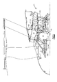
Figure 1 is a schematic cross-section of an embodiment of a gas turbine engine; -
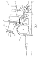
Figure 2 is an enlarged cross-section of a front center body assembly portion of the gas turbine engine embodiment shown inFigure 1 s; -
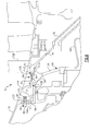
Figure 3 is an enlarged cross-section of the geared architecture of the gas turbine engine embodiment shown inFigure 1 ; -
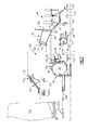
Figure 4 is an exploded perspective view of the front center body assembly of the turbine engine embodiment shown inFigure 1 ; -
Figure 5 is an enlarged perspective partial cross-section of a front center body support of the front center body assembly of the turbine engine embodiment shown inFigure 1 ; -
Figure 6 is an enlarged sectional view of the front center body support of the turbine engine embodiment shown inFigure 1 ; -
Figure 6A is a perspective view of the center body support of the turbine engine embodiment shown inFigure 1 ; -
Figure 6B is an end view of the center body support of the turbine engine embodiment shown inFigure 1 ; -
Figure 7 is an exploded view of the front center body support of the turbine engine embodiment shown inFigure 1 ; and -
Figure 8 is a schematic view of an embodiment of a forward gearbox removal from a gas turbine engine. -
Figure 1 schematically illustrates agas turbine engine 20. Thegas turbine engine 20 is disclosed herein as a two-spool turbofan that generally incorporates afan section 22, acompressor section 24, acombustor section 26 and aturbine section 28. Alternative engines might include an augmentor section (not shown) among other systems or features. Thefan section 22 drives air along a bypass flowpath B while thecompressor section 24 drives air along a core flowpath C for compression and communication into thecombustor section 26 then expansion through theturbine section 28. Although depicted as a turbofan gas turbine engine in the disclosed non-limiting embodiment, it should be understood that the concepts described herein are not limited to use with turbofans as the teachings may be applied to other types of turbine engines including three-spool architectures. - The
engine 20 generally includes alow speed spool 30 and ahigh speed spool 32 mounted for rotation about an engine central longitudinal axis A relative to an enginestatic structure 36 viaseveral bearing systems 38. Thelow speed spool 30 generally includes aninner shaft 40 that interconnects afan 42, a low pressure (or first)compressor section 44 and a low pressure (or first)turbine section 46. Theinner shaft 40 is connected to thefan 42 through a gearedarchitecture 48 to drive thefan 42 at a lower speed than thelow speed spool 30. A #2 bearingsupport 38A located within thecompressor section 24 supports a forward end of theinner shaft 40. It should be understood thatvarious bearing systems 38 at various locations may alternatively or additionally be provided. - The
high speed spool 32 includes anouter shaft 50 that interconnects a high pressure (or first)compressor section 52 and high pressure (or first)turbine section 54. Acombustor 56 is arranged between thehigh pressure compressor 52 and thehigh pressure turbine 54. As used herein, a "high pressure" compressor or turbine experiences a higher pressure than a corresponding "low pressure" compressor or turbine. - The core airflow C is compressed by the
low pressure compressor 44 then thehigh pressure compressor 52, mixed and burned with fuel in thecombustor 56, then expanded over thehigh pressure turbine 54 andlow pressure turbine 46. Theturbines low speed spool 30 andhigh speed spool 32 in response to the expansion. - The
engine 20 in one example is a high-bypass geared aircraft engine. In a further example, theengine 20 bypass ratio is greater than about six (6), with an example embodiment being greater than ten (10), the gearedarchitecture 48 is an epicyclic gear train, such as a planetary gear system or other gear system, with a gear reduction ratio of greater than about 2.3 and thelow pressure turbine 46 has a pressure ratio that is greater than about 5. In one example, the gearedarchitecture 48 includes a sun gear, a ring gear, and intermediate gears arranged circumferentially about the sun gear and intermeshing with the sun gear and the ring gear. The intermediate gears are star gears grounded to a flex support 68 (shown inFigure 6 ) against rotation about the axis A. The sun gear is supported by thelow speed spool 30, and the ring gear is interconnected to thefan 42. - In one disclosed embodiment, the
engine 20 bypass ratio is greater than about ten (10:1), the fan diameter is significantly larger than that of thelow pressure compressor 44, and thelow pressure turbine 46 has a pressure ratio that is greater than about 5:1.Low pressure turbine 46 pressure ratio is pressure measured prior to inlet oflow pressure turbine 46 as related to the pressure at the outlet of thelow pressure turbine 46 prior to an exhaust nozzle. The gearedarchitecture 48 may be an epicycle gear train, such as a planetary gear system or other gear system, with a gear reduction ratio of greater than about 2.5:1. It should be understood, however, that the above parameters are only exemplary of one embodiment of a geared architecture engine and that the present invention is applicable to other gas turbine engines including direct drive turbofans. - A significant amount of thrust is provided by a bypass flow B due to the high bypass ratio. The
fan section 22 of theengine 20 is designed for a particular flight condition -- typically cruise at about 0.8 Mach and about 35,000 feet (10668 m). The flight condition of 0.8 Mach and 35,000 ft (10668 m), with the engine at its best fuel consumption - also known as "bucket cruise Thrust Specific Fuel Consumption ('TSFC')" - is the industry standard parameter of lbm of fuel being burned divided by lbf of thrust the engine produces at that minimum point. "Low fan pressure ratio" is the pressure ratio across the fan blade alone, without a Fan Exit Guide Vane ("FEGV") system. The low fan pressure ratio as disclosed herein according to one non-limiting embodiment is less than about 1.45. "Low corrected fan tip speed" is the actual fan tip speed in ft/sec divided by an industry standard temperature correction of [(Tambient deg R) / 518.7)^0.5]. The "Low corrected fan tip speed" as disclosed herein according to one non-limiting embodiment is less than about 1150 ft / second (350.5 m/s). The above parameters for theengine 20 are intended to be exemplary. - With reference to
Figure 2 , the enginestatic structure 36 proximate thecompressor section 24 includes a frontcenter body assembly 60 adjacent to the #2bearing support 38A. The frontcenter body assembly 60 generally includes a frontcenter body support 62. The #2bearing support 38A generally includes aseal package 64, a bearingpackage 66 and a centeringspring 70. - With reference to
Figures 2 and3 , aflex support 68 provides a flexible attachment of the gearedarchitecture 48 within the front center body support 62 (also illustrated inFigure 4 ). Theflex support 68 reacts the torsional loads from the gearedarchitecture 48 and facilitates vibration absorption as well as other support functions. The centeringspring 70 is a generally cylindrical cage-like structural component with a multiple of beams that extend between flange end structures (also illustrated inFigure 4 ). The centeringspring 70 resiliently positions the bearingpackage 66 with respect to thelow spool 30. In one embodiment, the beams are double-tapered beams arrayed circumferentially to control a radial spring rate that may be selected based on a plurality of considerations including, but not limited to, bearing loading, bearing life, rotor dynamics, and rotor deflection considerations. - The front
center body support 62 includes a frontcenter body section 72 and abearing section 74 defined about axis A with a frustro-conical interface section 76 therebetween (Figure 5 ). The frontcenter body section 72 at least partially defines the core flowpath into thelow pressure compressor 44. The frontcenter body section 72 includes an annular core passage with circumferentially arranged frontcenter body vanes 71 having leading and trailingedges Figure 3 . The bearingsection 74 is defined radially inward of the frontcenter body section 72. The bearingsection 74 locates the bearingpackage 66 and theseal package 64 with respect to thelow spool 30. The frustro-conical interface section 76 combines the frontcenter body section 72 and thebearing section 74 to form a unified load path, substantially free of kinks typical of a conventional flange joint, from the bearingpackage 66 to the outer periphery of the enginestatic structure 36. The frustro-conical interface section 76 may include a weld W (Figure 5 ) or, alternatively, be an integral section such that the frontcenter body support 62 is a unitary component. - The integral, flange-less arrangement of the frustro-
conical interface section 76 facilitates a light weight, reduced part count architecture with an increased ability to tune the overall stiffness and achieve rotor dynamic requirements. Such an architecture also further integrates functions such as oil and air delivery within the bearing compartment which surroundsbearing package 66. - With reference to
Figure 6 , the frontcenter body support 62 includes mount features to receive theflex support 68. Theflex support 68 includes aconical support 158 that supports anintegral flex member 160, which provides a fold for absorbing vibrations. In one disclosed non-limiting embodiment, the mount features of the frontcenter body support 62 includes first splines 78, which are internal in the example, and radially inward directedfastener bosses 80 on the frontcenter body section 72. Theflex support 68 includes correspondingsecond splines 82, which are external in the example, and radially outwardly directedfastener flange 84. Theflex support 68 is received into the frontcenter body support 62 at asplined interface 86 formed by first andsecond splines fastener flange 84 abutsfastener bosses 80. Thesplined interface 86 transfers torque between the first andsecond splines fasteners 88, such as bolts, are threaded into thefastener bosses 80 and thefastener flange 84 to mount theflex support 68 within the frontcenter body support 62. Thefasteners 88 includeheads 89 facing forward for access from the front of theengine 20. - Referring to
Figures 5-6A , thecentral body support 62 provides an innerannular wall 128 for the core airflow C. Thevanes 71 interconnect the innerannular wall 128 to an outerannular wall 129 to provide a unitary structure. The first splines 78 includetooth groups 146 including multiple teeth. Thetooth groups 146 are circumferentially spaced apart from one another with untoothed regions arranged between the tooth groups 146. Thevanes 71 are circumferentially aligned with an untoothed region to structurally reinforce the interface between the first andsecond splines tooth groups 146 of thefirst splines 146. Corresponding untoothed regions are arranged between the tooth groups of thesecond splines 82. - In the example, the
fastener bosses 80 are arranged in clusters circumferentially spaced from one another, as shown inFigure 6A . Thefastener bosses 80 are aligned with the tooth groups 146. However, it should be understood that thefastener bosses 80 may be arranged in other configurations. Thefastener flange 84 extends radially outward from anannular flange 127 that axially extends from thesecond splines 82. Thefastener flange 84 includes anaft surface 142 that abuts aface 144 of thefastener bosses 80 to axially locate theflex support 68 relative to thecentral body support 62. Thefastener flange 84 includesapertures 132 that are arranged in clusters circumferentially spaced from one another and receive thefasteners 88, which are secured inholes 130 of thefastener bosses 80. Thefastener flange 84 may include interruptions or recesses that permit componentry to pass through theflex support 68 at the perimeter of thefasteners flange 84. - The untoothed region is provided by a stiffening
rail 148 protruding radially inward from thecentral body section 72 that provides the innerannular wall 128. Thecentral body support 62 includes anannular recess 150 and anannular pocket 152 that are axially spaced apart from one another to provide first and secondlateral sides rail 148. The teeth of thetooth groups 146 include roots provided at a first tooth radius T1 and extend radially inward to crests provided at a second tooth radius T2. As shown inFigure 6B , the stiffeningrail 148 extends radially inward to a rail radius R that is less than the first tooth radius T1, and in one example, equal to the second tooth radius T2. The stiffeningrail 148 and its circumferential alignment with thevanes 71 ensures improved cylindricity of thecentral body section 72 during engine operation. - The
central body support 62 includes a firstinner face 134 arranged near thefirst spline 78 and is provided by theannular recess 150. Theflex support 68 includes a firstouter face 138 arranged in an interference fit relationship at room temperature with the firstinner face 134 to radially locate theflex support 68 relative to thecentral body support 62. A secondinner face 136 is provided on thecentral body support 62, and theflex support 68 includes a secondouter face 140 arranged in an interference fit relationship at room temperature with the secondinner face 136. The first inner andouter faces first spline 78, and the second inner andouter faces first spline 78. The secondouter face 140 is smaller than the firstouter face 138 to facilitate assembly and disassembly of theflex support 68 from the front of theengine 20. - With reference to
Figure 7 , theheads 89 of thefasteners 88 are directed forward to provide access from a forward section of the frontcenter body assembly 60 opposite the bearingpackage 66 of the number twobearing system 38A. Thefasteners 88 are thereby readily removed to access agearbox 90 of the gearedarchitecture 48. - A fan shaft bearing support
front wall 102 aft of thefan 42 is mounted to a forward section of the frontcenter body support 62 to provide access to the gearedarchitecture 48 from the front of theengine 20. Thefront wall 102 includes aflange 103 mountable to the frontcenter body support 62 at theflange 61 by a multiple offasteners 105, whichfasteners 105 may in one non-limiting embodiment be bolts. Thefront wall 102 and the frontcenter body support 62 define a bearing compartment 100 (also shown inFigure 2 ) which mounts to thebearing package 66. Thefront wall 102 is removable such that thegearbox 90 may be accessed as a module. Thegearbox 90 may thereby be accessed to facilitate rapid on-wing service. - It should be appreciated that various bearing structures 104 (illustrated schematically and in
Figure 2 ) and seals 106 (illustrated schematically and inFigure 2 ) may be supported by thefront wall 102 to contain oil and support rotation of anoutput shaft 108. Theoutput shaft 108 connects with the gearedarchitecture 48 to drive thefan 42.Fan blades 42B extend from afan hub 110 which are mounted to theoutput shaft 108 for rotation therewith. It should be appreciated that the bearingstructures 104 and seals 106 may, in the disclosed non-limiting embodiment may be disassembled with thefront wall 102 as a unit after removal of thefan hub 110. - The
gearbox 90 is driven by the low spool 30 (Figure 1 ) through acoupling shaft 112. Thecoupling shaft 112 transfers torque through the bearingpackage 66 to thegearbox 90 as well as facilitates the segregation of vibrations and other transients. Thecoupling shaft 112 generally includes a forward coupling shaft section 114 and an aftcoupling shaft section 116 which extends from the bearingpackage 66, however, more or fewer pieces may be used to provide thecoupling shaft 112. The forward coupling shaft section 114 includes aninterface spline 118 which mates with anaft spline 120 of the aftcoupling shaft section 116. Aninterface spline 122 of the aftcoupling shaft section 116 connects thecoupling shaft 112 to thelow spool 30 through, in this non limiting embodiment, splined engagement with aspline 124 on a lowpressure compressor hub 126 of thelow pressure compressor 44. - As a high level summary, the front architecture of the
engine 20 is disassembled by detaching the fan module from a fan shaft bearing support. The fan shaft bearing support (front wall 102) remains secured to thecentral body support 62 over thegear box 90. The fan shaft bearing support (front wall 102) is detached from thecentral support body 62 without removing thegear box 90. The forward-facingfasteners 88 are accessed and removed. The first andsecond splines gear box 90 is removed with the fan shaft bearing support (front wall 102) and theflex support 68. The bearing 38A is left undisturbed. - To remove and isolate the
gearbox 90, thefan hub 110 is disassembled from theoutput shaft 108. The multiple offasteners 105 are then removed such that thefront wall 102 is disconnected from the frontcenter body support 62; thefront wall 102 is thereafter removed from the engine. The multiple offasteners 88 are then removed from the front of theengine 20. The gearedarchitecture 48 is then slid forward out of the frontcenter body support 62 such that theinterface spline 118 is slid off theaft spline 120 and theouter spline 82 is slid off theinternal spline 78. The gearedarchitecture 48 is thereby removable from theengine 20 as a module (Figure 8 ; illustrated schematically). It should be appreciated that other componentry may need to be disassembled to remove the gearedarchitecture 48 from theengine 20, however, such disassembly is relatively minor and need not be discussed in detail. It should be further appreciated that other components such as the bearingpackage 66 andseal 64 are also now readily accessible from the front of theengine 20. - Removal of the
gearbox 90 from the front of theengine 20 as disclosed saves significant time and expense. The gearedarchitecture 48, is removable from theengine 20 as a module and does not need to be further disassembled. Moreover, although the gearedarchitecture 48 must be removed from the engine to gain access to thebearing package 66 and theseal 64, the gearedarchitecture 48 does not need to be removed from theengine 20 to gain access to the engine core itself. - It should be understood that like reference numerals identify corresponding or similar elements throughout the several drawings. It should also be understood that although a particular component arrangement is disclosed in the illustrated embodiment, other arrangements will benefit herefrom.
- Although particular step sequences are shown, described, and claimed, it should be understood that steps may be performed in any order, separated or combined unless otherwise indicated and will still benefit from the present invention.
- Although the different examples have specific components shown in the illustrations, embodiments of this invention are not limited to those particular combinations. It is possible to use some of the components or features from one of the examples in combination with features or components from another one of the examples.
- The foregoing description is exemplary rather than defined by the limitations within. Various non-limiting embodiments are disclosed herein, however, one of ordinary skill in the art would recognize that various modifications and variations in light of the above teachings will fall within the scope of the appended claims. It is therefore to be understood that within the scope of the appended claims, the invention may be practiced other than as specifically described. For that reason the appended claims should be studied to determine true scope and content.
Claims (15)
- A gas turbine engine (10) comprising:a central body support (62) providing an inner annular wall for a core flow path, the central body support (62) including first splines (78);a geared architecture (48) interconnecting a spool (30) and a fan (42) rotatable about an axis; anda flex support (68) interconnecting the geared architecture (48) to the central body support (62), the flex support (68) including second splines (82) that intermesh with the first splines (78) for transferring torque there between.
- The gas turbine engine according to claim 1, wherein the central body support (62) includes circumferentially spaced apart vanes (71) radially extending between and interconnecting the inner annular wall and an outer annular wall.
- The gas turbine engine according to claim 1 or 2, wherein the first splines (78) include tooth groups (146) including multiple teeth, the tooth groups (146) circumferentially spaced apart from one another with untoothed regions (148) arranged between the tooth groups (146).
- The gas turbine engine according to claims 2 and 3, wherein the vanes (71) are circumferentially aligned with the untoothed regions (148).
- The gas turbine engine according to claim 3 or 4, wherein the second splines (82) include corresponding tooth groups configured to circumferentially align and mate with the tooth groups (146) of the first splines (78), and corresponding untoothed regions arranged between the tooth groups (146) of the corresponding tooth groups (146).
- The gas turbine engine according to any of claims 3 to 5, wherein the central body support (62) includes multiple fastener bosses (80) circumferentially spaced from one another, the fastener bosses (80) aligned with the tooth groups (146).
- The gas turbine engine according to any of claims 3 to 6, wherein the untoothed region (148) is provided by a stiffening rail (148) protruding radially inward from a central body section (72) providing the inner annular wall (128).
- The gas turbine engine according to claim 7, wherein the central body support (62) includes an annular recess (150) and an annular pocket (152) axially spaced apart from one another to provide first and second lateral sides (154,156) on the stiffening rail (148).
- The gas turbine engine according to claim 7 or 8, wherein the tooth groups (146) include internal teeth having roots provided at a first tooth radius (T1) and extending radially inward to crests provided at a second tooth radius (T2), the stiffening rail (148) extending radially inward to a rail radius (R) that is less than the first tooth radius (T1).
- The gas turbine engine according to any preceding claim, wherein the geared architecture (48) includes an epicyclic gear train having a sun gear, a ring gear, and intermediate gears arranged circumferentially about the sun gear and intermeshing with the sun gear and the ring gear, for example wherein the intermediate gears are star gears grounded to the flex support (68) against rotation about the axis, the sun gear is supported by the spool (30), and the ring gear is interconnected to the fan (42).
- The gas turbine engine according to any preceding claim, wherein the central body support (62) includes a first inner face (134) arranged near the first spline (78), and the flex support (68) includes a first outer face (138) arranged in an interference fit relationship with the first inner face (134) to radially locate the flex support (68) relative to the central body support (62), and wherein, optionally, the central body support (62) includes a second inner face (136), and the flex support (68) includes a second outer face (140) arranged in an interference fit relationship with the second inner face (136), the first inner and outer faces (134,138) arranged forward of the first spline (78) and the second inner and outer faces (136,140) arranged aft of the first spline (78), the second outer face (140) being positioned radially inward relative to the first outer face (138).
- The gas turbine engine according to any preceding claim, comprising fasteners (88) securing the flex support (68) to the central body support (62), the fasteners (88) including heads (89) facing forward, wherein the central body support (62) optionally includes circumferentially spaced fastener bosses (80), and the flex support (68) optionally includes a radially outward extending fastener flange (84) abutting the fastener bosses (80) to axially locate the flex support (68) relative to the central body support (62), the fastener flange (84) optionally including apertures (132) arranged circumferentially spaced from one another and receiving the fasteners (88).
- A method of disassembling a front architecture of a gas turbine engine, comprising the steps of:accessing forward-facing fasteners (88) that secure a central body support (62) to a flex support (68), wherein the flex support (68) includes a geared architecture (48) supported thereon;removing the fasteners (88); anddecoupling first and second splines (78,82) respectively provided on the central body support (62) and the flex support (68).
- The method according to claim 13, wherein the accessing step includes the step of detaching a fan module from a fan shaft bearing support (102), with the fan shaft bearing support (102) remaining secured to the central body support (62).
- The method according to claim 13 or 14, wherein the accessing step includes the step of detaching the fan shaft bearing support (102) from the central support body (62) without removing the geared architecture (48), and/or wherein the decoupling step includes removing a geared architecture (48) module that includes the geared architecture and the flex support (68), wherein the decoupling step leaves undisturbed a bearing supporting a front of a spool operatively connectable with the geared architecture (48).
Priority Applications (1)
| Application Number | Priority Date | Filing Date | Title |
|---|---|---|---|
| EP19150803.5A EP3489472B8 (en) | 2011-10-17 | 2012-10-12 | Gas turbine engine front center body architecture |
Applications Claiming Priority (3)
| Application Number | Priority Date | Filing Date | Title |
|---|---|---|---|
| US201113275286A | 2011-10-17 | 2011-10-17 | |
| US13/282,919 US8366385B2 (en) | 2011-04-15 | 2011-10-27 | Gas turbine engine front center body architecture |
| US13/407,916 US8360714B2 (en) | 2011-04-15 | 2012-02-29 | Gas turbine engine front center body architecture |
Related Child Applications (1)
| Application Number | Title | Priority Date | Filing Date |
|---|---|---|---|
| EP19150803.5A Division EP3489472B8 (en) | 2011-10-17 | 2012-10-12 | Gas turbine engine front center body architecture |
Publications (3)
| Publication Number | Publication Date |
|---|---|
| EP2584153A2 true EP2584153A2 (en) | 2013-04-24 |
| EP2584153A3 EP2584153A3 (en) | 2015-10-14 |
| EP2584153B1 EP2584153B1 (en) | 2019-01-09 |
Family
ID=47002768
Family Applications (2)
| Application Number | Title | Priority Date | Filing Date |
|---|---|---|---|
| EP12188414.2A Active EP2584153B1 (en) | 2011-10-17 | 2012-10-12 | Gas turbine engine and method of disassembly |
| EP19150803.5A Revoked EP3489472B8 (en) | 2011-10-17 | 2012-10-12 | Gas turbine engine front center body architecture |
Family Applications After (1)
| Application Number | Title | Priority Date | Filing Date |
|---|---|---|---|
| EP19150803.5A Revoked EP3489472B8 (en) | 2011-10-17 | 2012-10-12 | Gas turbine engine front center body architecture |
Country Status (2)
| Country | Link |
|---|---|
| EP (2) | EP2584153B1 (en) |
| RU (2) | RU2522344C2 (en) |
Cited By (9)
| Publication number | Priority date | Publication date | Assignee | Title |
|---|---|---|---|---|
| WO2015006149A1 (en) | 2013-07-07 | 2015-01-15 | United Technologies Corporation | Adjustable flange material and torque path isolation for splined fan drive gear system flexible support |
| EP3027866A1 (en) * | 2013-07-31 | 2016-06-08 | United Technologies Corporation | Lpc flowpath shape with gas turbine engine shaft bearing configuration |
| US10215094B2 (en) | 2012-01-31 | 2019-02-26 | United Technologies Corporation | Gas turbine engine shaft bearing configuration |
| US10400629B2 (en) | 2012-01-31 | 2019-09-03 | United Technologies Corporation | Gas turbine engine shaft bearing configuration |
| EP3779167A3 (en) * | 2011-11-23 | 2021-03-03 | Raytheon Technologies Corporation | Gas turbine engine architecture with low pressure compressor hub between high and low rotor thrust bearings |
| US11401831B2 (en) | 2012-01-31 | 2022-08-02 | Raytheon Technologies Corporation | Gas turbine engine shaft bearing configuration |
| EP4039940A1 (en) * | 2021-02-05 | 2022-08-10 | Pratt & Whitney Canada Corp. | Gas turbine engine assembly and method of disassembling same |
| EP4273391A1 (en) * | 2022-05-04 | 2023-11-08 | Safran Transmission Systems | Pre-assembly method for an aircraft turbine engine |
| US12103709B2 (en) | 2022-05-04 | 2024-10-01 | Safran Transmission Systems | Pre-assembly method for an aircraft turbomachine |
Families Citing this family (1)
| Publication number | Priority date | Publication date | Assignee | Title |
|---|---|---|---|---|
| FR3128264B1 (en) * | 2021-10-14 | 2024-02-09 | Safran Trans Systems | Improved device and method for centering an annular assembly of a planetary gearbox |
Family Cites Families (10)
| Publication number | Priority date | Publication date | Assignee | Title |
|---|---|---|---|---|
| US3922852A (en) * | 1973-10-17 | 1975-12-02 | Gen Electric | Variable pitch fan for gas turbine engine |
| US5433674A (en) * | 1994-04-12 | 1995-07-18 | United Technologies Corporation | Coupling system for a planetary gear train |
| US6223616B1 (en) * | 1999-12-22 | 2001-05-01 | United Technologies Corporation | Star gear system with lubrication circuit and lubrication method therefor |
| US8585538B2 (en) * | 2006-07-05 | 2013-11-19 | United Technologies Corporation | Coupling system for a star gear train in a gas turbine engine |
| US7704178B2 (en) | 2006-07-05 | 2010-04-27 | United Technologies Corporation | Oil baffle for gas turbine fan drive gear system |
| US7926260B2 (en) * | 2006-07-05 | 2011-04-19 | United Technologies Corporation | Flexible shaft for gas turbine engine |
| US8753243B2 (en) * | 2006-08-15 | 2014-06-17 | United Technologies Corporation | Ring gear mounting arrangement with oil scavenge scheme |
| RU2330170C2 (en) * | 2006-09-11 | 2008-07-27 | Открытое акционерное общество "Авиадвигатель" | Enhanced dual-flow turbo jet engine |
| US7662059B2 (en) | 2006-10-18 | 2010-02-16 | United Technologies Corporation | Lubrication of windmilling journal bearings |
| US20120260669A1 (en) | 2011-04-15 | 2012-10-18 | Davis Todd A | Front centerbody support for a gas turbine engine |
-
2012
- 2012-10-12 EP EP12188414.2A patent/EP2584153B1/en active Active
- 2012-10-12 EP EP19150803.5A patent/EP3489472B8/en not_active Revoked
- 2012-10-15 RU RU2012143797/06A patent/RU2522344C2/en active
- 2012-10-15 RU RU2014116447/06A patent/RU2567483C2/en active
Non-Patent Citations (1)
| Title |
|---|
| None |
Cited By (16)
| Publication number | Priority date | Publication date | Assignee | Title |
|---|---|---|---|---|
| EP3779167A3 (en) * | 2011-11-23 | 2021-03-03 | Raytheon Technologies Corporation | Gas turbine engine architecture with low pressure compressor hub between high and low rotor thrust bearings |
| US11149689B2 (en) | 2012-01-31 | 2021-10-19 | Raytheon Technologies Corporation | Gas turbine engine shaft bearing configuration |
| US11566586B2 (en) | 2012-01-31 | 2023-01-31 | Raytheon Technologies Corporation | Gas turbine engine shaft bearing configuration |
| US11486269B2 (en) | 2012-01-31 | 2022-11-01 | Raytheon Technologies Corporation | Gas turbine engine shaft bearing configuration |
| US10215094B2 (en) | 2012-01-31 | 2019-02-26 | United Technologies Corporation | Gas turbine engine shaft bearing configuration |
| US11401831B2 (en) | 2012-01-31 | 2022-08-02 | Raytheon Technologies Corporation | Gas turbine engine shaft bearing configuration |
| US10400629B2 (en) | 2012-01-31 | 2019-09-03 | United Technologies Corporation | Gas turbine engine shaft bearing configuration |
| US10267176B2 (en) | 2013-07-07 | 2019-04-23 | United Technolgies Corporation | Adjustable flange material and torque path isolation for splined fan drive gear system flexible support |
| WO2015006149A1 (en) | 2013-07-07 | 2015-01-15 | United Technologies Corporation | Adjustable flange material and torque path isolation for splined fan drive gear system flexible support |
| EP3027866A4 (en) * | 2013-07-31 | 2017-04-26 | United Technologies Corporation | Lpc flowpath shape with gas turbine engine shaft bearing configuration |
| EP3027866A1 (en) * | 2013-07-31 | 2016-06-08 | United Technologies Corporation | Lpc flowpath shape with gas turbine engine shaft bearing configuration |
| EP4039940A1 (en) * | 2021-02-05 | 2022-08-10 | Pratt & Whitney Canada Corp. | Gas turbine engine assembly and method of disassembling same |
| US11578616B2 (en) | 2021-02-05 | 2023-02-14 | Pratt & Whitney Canada Corp. | Gas turbine engine assembly and method of disassembling same |
| EP4273391A1 (en) * | 2022-05-04 | 2023-11-08 | Safran Transmission Systems | Pre-assembly method for an aircraft turbine engine |
| FR3135303A1 (en) * | 2022-05-04 | 2023-11-10 | Safran Transmission Systems | Pre-assembly process for an aircraft turbomachine |
| US12103709B2 (en) | 2022-05-04 | 2024-10-01 | Safran Transmission Systems | Pre-assembly method for an aircraft turbomachine |
Also Published As
| Publication number | Publication date |
|---|---|
| EP3489472B8 (en) | 2021-04-07 |
| EP2584153A3 (en) | 2015-10-14 |
| RU2014116447A (en) | 2015-08-20 |
| EP3489472A1 (en) | 2019-05-29 |
| EP3489472B1 (en) | 2021-01-13 |
| RU2012143797A (en) | 2014-04-20 |
| RU2567483C2 (en) | 2015-11-10 |
| EP2584153B1 (en) | 2019-01-09 |
| RU2522344C2 (en) | 2014-07-10 |
Similar Documents
| Publication | Publication Date | Title |
|---|---|---|
| US8360714B2 (en) | Gas turbine engine front center body architecture | |
| CA2789325C (en) | Gas turbine engine front center body architecture | |
| EP3489472B1 (en) | Gas turbine engine front center body architecture | |
| US8366385B2 (en) | Gas turbine engine front center body architecture | |
| US11486269B2 (en) | Gas turbine engine shaft bearing configuration | |
| EP2511500B1 (en) | A gas turbine engine and method of assembling the same | |
| US10436116B2 (en) | Gas turbine engine geared architecture axial retention arrangement | |
| US11713713B2 (en) | Gas turbine engine front center body architecture | |
| WO2014137574A1 (en) | Mid-turbine frame rod and turbine case flange | |
| CA2789465C (en) | Gas turbine engine front center body architecture | |
| WO2015017041A1 (en) | Gas turbine engine shaft bearing configuration | |
| US20230272745A1 (en) | Gas turbine engine front center body architecture | |
| WO2013130373A1 (en) | Gas turbine engine front center body architecture | |
| EP2584154B1 (en) | Gas turbine front center body architecture and method of servicing a gas turbine engine |
Legal Events
| Date | Code | Title | Description |
|---|---|---|---|
| PUAI | Public reference made under article 153(3) epc to a published international application that has entered the european phase |
Free format text: ORIGINAL CODE: 0009012 |
|
| AK | Designated contracting states |
Kind code of ref document: A2 Designated state(s): AL AT BE BG CH CY CZ DE DK EE ES FI FR GB GR HR HU IE IS IT LI LT LU LV MC MK MT NL NO PL PT RO RS SE SI SK SM TR |
|
| AX | Request for extension of the european patent |
Extension state: BA ME |
|
| 17P | Request for examination filed |
Effective date: 20150707 |
|
| RBV | Designated contracting states (corrected) |
Designated state(s): AL AT BE BG CH CY CZ DE DK EE ES FI FR GB GR HR HU IE IS IT LI LT LU LV MC MK MT NL NO PL PT RO RS SE SI SK SM TR |
|
| PUAL | Search report despatched |
Free format text: ORIGINAL CODE: 0009013 |
|
| AK | Designated contracting states |
Kind code of ref document: A3 Designated state(s): AL AT BE BG CH CY CZ DE DK EE ES FI FR GB GR HR HU IE IS IT LI LT LU LV MC MK MT NL NO PL PT RO RS SE SI SK SM TR |
|
| AX | Request for extension of the european patent |
Extension state: BA ME |
|
| RIC1 | Information provided on ipc code assigned before grant |
Ipc: F02C 7/06 20060101ALI20150910BHEP Ipc: F01D 5/06 20060101ALI20150910BHEP Ipc: F02K 3/06 20060101ALI20150910BHEP Ipc: F02C 7/36 20060101ALI20150910BHEP Ipc: F02C 3/107 20060101ALI20150910BHEP Ipc: F02C 7/20 20060101ALI20150910BHEP Ipc: F01D 25/16 20060101AFI20150910BHEP |
|
| 17Q | First examination report despatched |
Effective date: 20160823 |
|
| RAP1 | Party data changed (applicant data changed or rights of an application transferred) |
Owner name: UNITED TECHNOLOGIES CORPORATION |
|
| STAA | Information on the status of an ep patent application or granted ep patent |
Free format text: STATUS: EXAMINATION IS IN PROGRESS |
|
| GRAP | Despatch of communication of intention to grant a patent |
Free format text: ORIGINAL CODE: EPIDOSNIGR1 |
|
| STAA | Information on the status of an ep patent application or granted ep patent |
Free format text: STATUS: GRANT OF PATENT IS INTENDED |
|
| INTG | Intention to grant announced |
Effective date: 20180719 |
|
| GRAS | Grant fee paid |
Free format text: ORIGINAL CODE: EPIDOSNIGR3 |
|
| GRAA | (expected) grant |
Free format text: ORIGINAL CODE: 0009210 |
|
| STAA | Information on the status of an ep patent application or granted ep patent |
Free format text: STATUS: THE PATENT HAS BEEN GRANTED |
|
| AK | Designated contracting states |
Kind code of ref document: B1 Designated state(s): AL AT BE BG CH CY CZ DE DK EE ES FI FR GB GR HR HU IE IS IT LI LT LU LV MC MK MT NL NO PL PT RO RS SE SI SK SM TR |
|
| REG | Reference to a national code |
Ref country code: GB Ref legal event code: FG4D |
|
| REG | Reference to a national code |
Ref country code: CH Ref legal event code: EP Ref country code: AT Ref legal event code: REF Ref document number: 1087562 Country of ref document: AT Kind code of ref document: T Effective date: 20190115 |
|
| REG | Reference to a national code |
Ref country code: DE Ref legal event code: R096 Ref document number: 602012055631 Country of ref document: DE |
|
| REG | Reference to a national code |
Ref country code: IE Ref legal event code: FG4D |
|
| REG | Reference to a national code |
Ref country code: SE Ref legal event code: TRGR |
|
| REG | Reference to a national code |
Ref country code: NL Ref legal event code: MP Effective date: 20190109 |
|
| REG | Reference to a national code |
Ref country code: LT Ref legal event code: MG4D |
|
| PG25 | Lapsed in a contracting state [announced via postgrant information from national office to epo] |
Ref country code: NL Free format text: LAPSE BECAUSE OF FAILURE TO SUBMIT A TRANSLATION OF THE DESCRIPTION OR TO PAY THE FEE WITHIN THE PRESCRIBED TIME-LIMIT Effective date: 20190109 |
|
| REG | Reference to a national code |
Ref country code: AT Ref legal event code: MK05 Ref document number: 1087562 Country of ref document: AT Kind code of ref document: T Effective date: 20190109 |
|
| PG25 | Lapsed in a contracting state [announced via postgrant information from national office to epo] |
Ref country code: ES Free format text: LAPSE BECAUSE OF FAILURE TO SUBMIT A TRANSLATION OF THE DESCRIPTION OR TO PAY THE FEE WITHIN THE PRESCRIBED TIME-LIMIT Effective date: 20190109 Ref country code: PT Free format text: LAPSE BECAUSE OF FAILURE TO SUBMIT A TRANSLATION OF THE DESCRIPTION OR TO PAY THE FEE WITHIN THE PRESCRIBED TIME-LIMIT Effective date: 20190509 Ref country code: FI Free format text: LAPSE BECAUSE OF FAILURE TO SUBMIT A TRANSLATION OF THE DESCRIPTION OR TO PAY THE FEE WITHIN THE PRESCRIBED TIME-LIMIT Effective date: 20190109 Ref country code: NO Free format text: LAPSE BECAUSE OF FAILURE TO SUBMIT A TRANSLATION OF THE DESCRIPTION OR TO PAY THE FEE WITHIN THE PRESCRIBED TIME-LIMIT Effective date: 20190409 Ref country code: LT Free format text: LAPSE BECAUSE OF FAILURE TO SUBMIT A TRANSLATION OF THE DESCRIPTION OR TO PAY THE FEE WITHIN THE PRESCRIBED TIME-LIMIT Effective date: 20190109 Ref country code: PL Free format text: LAPSE BECAUSE OF FAILURE TO SUBMIT A TRANSLATION OF THE DESCRIPTION OR TO PAY THE FEE WITHIN THE PRESCRIBED TIME-LIMIT Effective date: 20190109 |
|
| PG25 | Lapsed in a contracting state [announced via postgrant information from national office to epo] |
Ref country code: IS Free format text: LAPSE BECAUSE OF FAILURE TO SUBMIT A TRANSLATION OF THE DESCRIPTION OR TO PAY THE FEE WITHIN THE PRESCRIBED TIME-LIMIT Effective date: 20190509 Ref country code: HR Free format text: LAPSE BECAUSE OF FAILURE TO SUBMIT A TRANSLATION OF THE DESCRIPTION OR TO PAY THE FEE WITHIN THE PRESCRIBED TIME-LIMIT Effective date: 20190109 Ref country code: LV Free format text: LAPSE BECAUSE OF FAILURE TO SUBMIT A TRANSLATION OF THE DESCRIPTION OR TO PAY THE FEE WITHIN THE PRESCRIBED TIME-LIMIT Effective date: 20190109 Ref country code: RS Free format text: LAPSE BECAUSE OF FAILURE TO SUBMIT A TRANSLATION OF THE DESCRIPTION OR TO PAY THE FEE WITHIN THE PRESCRIBED TIME-LIMIT Effective date: 20190109 Ref country code: BG Free format text: LAPSE BECAUSE OF FAILURE TO SUBMIT A TRANSLATION OF THE DESCRIPTION OR TO PAY THE FEE WITHIN THE PRESCRIBED TIME-LIMIT Effective date: 20190409 Ref country code: GR Free format text: LAPSE BECAUSE OF FAILURE TO SUBMIT A TRANSLATION OF THE DESCRIPTION OR TO PAY THE FEE WITHIN THE PRESCRIBED TIME-LIMIT Effective date: 20190410 |
|
| REG | Reference to a national code |
Ref country code: DE Ref legal event code: R097 Ref document number: 602012055631 Country of ref document: DE |
|
| PG25 | Lapsed in a contracting state [announced via postgrant information from national office to epo] |
Ref country code: IT Free format text: LAPSE BECAUSE OF FAILURE TO SUBMIT A TRANSLATION OF THE DESCRIPTION OR TO PAY THE FEE WITHIN THE PRESCRIBED TIME-LIMIT Effective date: 20190109 Ref country code: RO Free format text: LAPSE BECAUSE OF FAILURE TO SUBMIT A TRANSLATION OF THE DESCRIPTION OR TO PAY THE FEE WITHIN THE PRESCRIBED TIME-LIMIT Effective date: 20190109 Ref country code: CZ Free format text: LAPSE BECAUSE OF FAILURE TO SUBMIT A TRANSLATION OF THE DESCRIPTION OR TO PAY THE FEE WITHIN THE PRESCRIBED TIME-LIMIT Effective date: 20190109 Ref country code: DK Free format text: LAPSE BECAUSE OF FAILURE TO SUBMIT A TRANSLATION OF THE DESCRIPTION OR TO PAY THE FEE WITHIN THE PRESCRIBED TIME-LIMIT Effective date: 20190109 Ref country code: AT Free format text: LAPSE BECAUSE OF FAILURE TO SUBMIT A TRANSLATION OF THE DESCRIPTION OR TO PAY THE FEE WITHIN THE PRESCRIBED TIME-LIMIT Effective date: 20190109 Ref country code: EE Free format text: LAPSE BECAUSE OF FAILURE TO SUBMIT A TRANSLATION OF THE DESCRIPTION OR TO PAY THE FEE WITHIN THE PRESCRIBED TIME-LIMIT Effective date: 20190109 Ref country code: SK Free format text: LAPSE BECAUSE OF FAILURE TO SUBMIT A TRANSLATION OF THE DESCRIPTION OR TO PAY THE FEE WITHIN THE PRESCRIBED TIME-LIMIT Effective date: 20190109 Ref country code: AL Free format text: LAPSE BECAUSE OF FAILURE TO SUBMIT A TRANSLATION OF THE DESCRIPTION OR TO PAY THE FEE WITHIN THE PRESCRIBED TIME-LIMIT Effective date: 20190109 |
|
| PLBE | No opposition filed within time limit |
Free format text: ORIGINAL CODE: 0009261 |
|
| STAA | Information on the status of an ep patent application or granted ep patent |
Free format text: STATUS: NO OPPOSITION FILED WITHIN TIME LIMIT |
|
| PG25 | Lapsed in a contracting state [announced via postgrant information from national office to epo] |
Ref country code: SM Free format text: LAPSE BECAUSE OF FAILURE TO SUBMIT A TRANSLATION OF THE DESCRIPTION OR TO PAY THE FEE WITHIN THE PRESCRIBED TIME-LIMIT Effective date: 20190109 |
|
| 26N | No opposition filed |
Effective date: 20191010 |
|
| PG25 | Lapsed in a contracting state [announced via postgrant information from national office to epo] |
Ref country code: SI Free format text: LAPSE BECAUSE OF FAILURE TO SUBMIT A TRANSLATION OF THE DESCRIPTION OR TO PAY THE FEE WITHIN THE PRESCRIBED TIME-LIMIT Effective date: 20190109 |
|
| PG25 | Lapsed in a contracting state [announced via postgrant information from national office to epo] |
Ref country code: MC Free format text: LAPSE BECAUSE OF FAILURE TO SUBMIT A TRANSLATION OF THE DESCRIPTION OR TO PAY THE FEE WITHIN THE PRESCRIBED TIME-LIMIT Effective date: 20190109 |
|
| REG | Reference to a national code |
Ref country code: CH Ref legal event code: PL |
|
| PG25 | Lapsed in a contracting state [announced via postgrant information from national office to epo] |
Ref country code: CH Free format text: LAPSE BECAUSE OF NON-PAYMENT OF DUE FEES Effective date: 20191031 Ref country code: LI Free format text: LAPSE BECAUSE OF NON-PAYMENT OF DUE FEES Effective date: 20191031 Ref country code: LU Free format text: LAPSE BECAUSE OF NON-PAYMENT OF DUE FEES Effective date: 20191012 |
|
| REG | Reference to a national code |
Ref country code: BE Ref legal event code: MM Effective date: 20191031 |
|
| PG25 | Lapsed in a contracting state [announced via postgrant information from national office to epo] |
Ref country code: BE Free format text: LAPSE BECAUSE OF NON-PAYMENT OF DUE FEES Effective date: 20191031 |
|
| PG25 | Lapsed in a contracting state [announced via postgrant information from national office to epo] |
Ref country code: IE Free format text: LAPSE BECAUSE OF NON-PAYMENT OF DUE FEES Effective date: 20191012 |
|
| PG25 | Lapsed in a contracting state [announced via postgrant information from national office to epo] |
Ref country code: CY Free format text: LAPSE BECAUSE OF FAILURE TO SUBMIT A TRANSLATION OF THE DESCRIPTION OR TO PAY THE FEE WITHIN THE PRESCRIBED TIME-LIMIT Effective date: 20190109 |
|
| PG25 | Lapsed in a contracting state [announced via postgrant information from national office to epo] |
Ref country code: HU Free format text: LAPSE BECAUSE OF FAILURE TO SUBMIT A TRANSLATION OF THE DESCRIPTION OR TO PAY THE FEE WITHIN THE PRESCRIBED TIME-LIMIT; INVALID AB INITIO Effective date: 20121012 Ref country code: MT Free format text: LAPSE BECAUSE OF FAILURE TO SUBMIT A TRANSLATION OF THE DESCRIPTION OR TO PAY THE FEE WITHIN THE PRESCRIBED TIME-LIMIT Effective date: 20190109 |
|
| PG25 | Lapsed in a contracting state [announced via postgrant information from national office to epo] |
Ref country code: MK Free format text: LAPSE BECAUSE OF FAILURE TO SUBMIT A TRANSLATION OF THE DESCRIPTION OR TO PAY THE FEE WITHIN THE PRESCRIBED TIME-LIMIT Effective date: 20190109 |
|
| REG | Reference to a national code |
Ref country code: DE Ref legal event code: R081 Ref document number: 602012055631 Country of ref document: DE Owner name: RAYTHEON TECHNOLOGIES CORPORATION (N.D.GES.D.S, US Free format text: FORMER OWNER: UNITED TECHNOLOGIES CORPORATION, FARMINGTON, CONN., US |
|
| P01 | Opt-out of the competence of the unified patent court (upc) registered |
Effective date: 20230520 |
|
| PGFP | Annual fee paid to national office [announced via postgrant information from national office to epo] |
Ref country code: TR Payment date: 20230927 Year of fee payment: 12 Ref country code: GB Payment date: 20230920 Year of fee payment: 12 |
|
| PGFP | Annual fee paid to national office [announced via postgrant information from national office to epo] |
Ref country code: SE Payment date: 20230922 Year of fee payment: 12 Ref country code: FR Payment date: 20230920 Year of fee payment: 12 |
|
| PGFP | Annual fee paid to national office [announced via postgrant information from national office to epo] |
Ref country code: DE Payment date: 20230920 Year of fee payment: 12 |