EP2584115B1 - Spreading and screeding device for finishing a screed floor, and method therefor - Google Patents
Spreading and screeding device for finishing a screed floor, and method therefor Download PDFInfo
- Publication number
- EP2584115B1 EP2584115B1 EP12186871.5A EP12186871A EP2584115B1 EP 2584115 B1 EP2584115 B1 EP 2584115B1 EP 12186871 A EP12186871 A EP 12186871A EP 2584115 B1 EP2584115 B1 EP 2584115B1
- Authority
- EP
- European Patent Office
- Prior art keywords
- spreading
- roller
- pressing
- floor
- screeding device
- Prior art date
- Legal status (The legal status is an assumption and is not a legal conclusion. Google has not performed a legal analysis and makes no representation as to the accuracy of the status listed.)
- Active
Links
- 238000003892 spreading Methods 0.000 title claims description 54
- 230000007480 spreading Effects 0.000 title claims description 54
- 238000000034 method Methods 0.000 title claims description 7
- 238000003825 pressing Methods 0.000 claims description 31
- 239000000463 material Substances 0.000 claims description 26
- 239000004568 cement Substances 0.000 claims description 14
- 238000006073 displacement reaction Methods 0.000 claims description 3
- 238000004519 manufacturing process Methods 0.000 claims description 3
- 238000010276 construction Methods 0.000 description 3
- 238000007599 discharging Methods 0.000 description 3
- 239000004570 mortar (masonry) Substances 0.000 description 3
- 239000004576 sand Substances 0.000 description 3
- 230000000694 effects Effects 0.000 description 2
- 230000007246 mechanism Effects 0.000 description 2
- 239000011346 highly viscous material Substances 0.000 description 1
- 239000000203 mixture Substances 0.000 description 1
- 238000012986 modification Methods 0.000 description 1
- 230000004048 modification Effects 0.000 description 1
- 230000008569 process Effects 0.000 description 1
- 238000005096 rolling process Methods 0.000 description 1
- 238000007789 sealing Methods 0.000 description 1
- 238000011144 upstream manufacturing Methods 0.000 description 1
- 239000011345 viscous material Substances 0.000 description 1
Images

Classifications
-
- E—FIXED CONSTRUCTIONS
- E01—CONSTRUCTION OF ROADS, RAILWAYS, OR BRIDGES
- E01C—CONSTRUCTION OF, OR SURFACES FOR, ROADS, SPORTS GROUNDS, OR THE LIKE; MACHINES OR AUXILIARY TOOLS FOR CONSTRUCTION OR REPAIR
- E01C19/00—Machines, tools or auxiliary devices for preparing or distributing paving materials, for working the placed materials, or for forming, consolidating, or finishing the paving
- E01C19/22—Machines, tools or auxiliary devices for preparing or distributing paving materials, for working the placed materials, or for forming, consolidating, or finishing the paving for consolidating or finishing laid-down unset materials
- E01C19/23—Rollers therefor; Such rollers usable also for compacting soil
- E01C19/26—Rollers therefor; Such rollers usable also for compacting soil self-propelled or fitted to road vehicles
- E01C19/262—Rollers therefor; Such rollers usable also for compacting soil self-propelled or fitted to road vehicles pedestrian-controlled, e.g. with safety arrangements for operator
-
- E—FIXED CONSTRUCTIONS
- E01—CONSTRUCTION OF ROADS, RAILWAYS, OR BRIDGES
- E01C—CONSTRUCTION OF, OR SURFACES FOR, ROADS, SPORTS GROUNDS, OR THE LIKE; MACHINES OR AUXILIARY TOOLS FOR CONSTRUCTION OR REPAIR
- E01C19/00—Machines, tools or auxiliary devices for preparing or distributing paving materials, for working the placed materials, or for forming, consolidating, or finishing the paving
- E01C19/12—Machines, tools or auxiliary devices for preparing or distributing paving materials, for working the placed materials, or for forming, consolidating, or finishing the paving for distributing granular or liquid materials
- E01C19/18—Devices for distributing road-metals mixed with binders, e.g. cement, bitumen, without consolidating or ironing effect
- E01C19/187—Devices for distributing road-metals mixed with binders, e.g. cement, bitumen, without consolidating or ironing effect solely for spreading-out or striking-off deposited mixtures, e.g. spread-out screws, strike-off boards
-
- E—FIXED CONSTRUCTIONS
- E01—CONSTRUCTION OF ROADS, RAILWAYS, OR BRIDGES
- E01C—CONSTRUCTION OF, OR SURFACES FOR, ROADS, SPORTS GROUNDS, OR THE LIKE; MACHINES OR AUXILIARY TOOLS FOR CONSTRUCTION OR REPAIR
- E01C19/00—Machines, tools or auxiliary devices for preparing or distributing paving materials, for working the placed materials, or for forming, consolidating, or finishing the paving
- E01C19/22—Machines, tools or auxiliary devices for preparing or distributing paving materials, for working the placed materials, or for forming, consolidating, or finishing the paving for consolidating or finishing laid-down unset materials
- E01C19/23—Rollers therefor; Such rollers usable also for compacting soil
- E01C19/26—Rollers therefor; Such rollers usable also for compacting soil self-propelled or fitted to road vehicles
- E01C19/264—Rollers therefor; Such rollers usable also for compacting soil self-propelled or fitted to road vehicles with attachments for work other than rolling, e.g. grading, scarifying
-
- E—FIXED CONSTRUCTIONS
- E04—BUILDING
- E04F—FINISHING WORK ON BUILDINGS, e.g. STAIRS, FLOORS
- E04F21/00—Implements for finishing work on buildings
- E04F21/20—Implements for finishing work on buildings for laying flooring
- E04F21/24—Implements for finishing work on buildings for laying flooring of masses made in situ, e.g. smoothing tools
- E04F21/245—Rotary power trowels, i.e. helicopter trowels
- E04F21/248—Rotary power trowels, i.e. helicopter trowels used by an operator walking behind the trowel, i.e. walk-behind power trowels
Definitions
- the invention relates to a spreading and screeding device.
- a spreading and screeding device can be used according to the invention to finish a screed floor, particularly a cement screed floor.
- US 1 731 231 A discloses an apparatus for spreading plastic material.
- US 3 515 042 A discloses a concrete vibrating and finishing machine.
- EP 1 865 108 A1 discloses a device for providing a floor surface.
- An object of the present invention is to obviate or reduce the above stated problems and to provide a device suitable for realizing a screed floor.
- the displaceable frame achieves that the device is displaceable over the floor where the screed floor has to be realized.
- This screed floor preferably relates to a cement screed floor, or sand cement screed floor.
- the frame is provided here with a roller for levelling the screed floor. This roller particularly provides for levelling of the cement for the purpose of thereby realizing a cement screed floor which is even and as level as possible.
- the frame is operatively connected to a pressing and spreading roller for spreading the screed floor material for the purpose of a good operation of the roller. During use this pressing and spreading roller is placed functionally in front of the roller. This pressing and spreading roller is therefore provided upstream of the roller in the usual forward direction of the frame.
- the cement is hereby first spread and pressed, or compacted, using this first roller, after which the roller as second roller subsequently levels the floor as a finish.
- the screed floor material can be spread, pressed, or compacted, as well as levelled in one operation. This significantly reduces the number of operations required. It has for instance been found that about 100 m 2 /hour of floor can be realized with the device according to the invention while, under the same conditions and with the same set requirements for the finished floor, four skilled workers would be necessary for this purpose. In addition, the reproducibility of the screed floor is greatly improved, whereby a constant quality can be provided for the floor.
- a uniform finish is realized by making use of the roller. Making use of a separate pressing and spreading roller realizes a uniform spreading of the material over the floor, which is then pressed down by the roller. A much more even and uniform spreading and pressing is hereby realized than is possible using for instance conventional vibrating devices. Within the context of the present invention, pressing is understood to mean compacting of the material.
- the pressing and spreading roller comprises a worm-like roller.
- the eccentric worm roller in the device according to the invention provides for a gentle displacement and spreading of the material which is particularly suitable for viscous material such as mortar. This results in a highly effective device. It has been found that a slightly higher positioning of the pressing and spreading roller in vertical direction over a distance of about 0 to 1 cm relative to the roller has advantageous results. The specific setting depends on, among other factors, the precise composition of the material used. If desired, it is also possible to set the two rollers to the same height.
- the pressing and spreading roller comprises a spiral-shaped roller.
- a spiral-shaped roller is for instance suitable for highly viscous materials for processing, wherein there is more emphasis on the spreading and less on the pressing of the material.
- the device further comprises an auger for spreading screed floor material over the width of the device.
- the auger By providing a separate auger possible excess material arranged for the screed floor which is thrown up by the pressing and spreading roller can be discharged laterally for the purpose of thereby achieving a better spreading of the material over the width of the device.
- the auger is provided above and more preferably at an angle behind the pressing and spreading roller on the device.
- This auger is also preferably provided, as seen in longitudinal direction of the device, just in front of the roller. It has been found that the most optimal effect of the separate auger is hereby achieved.
- the device according to the invention is provided with at least one opening arranged on the side of the displaceable frame for discharging an excess of screed floor material.
- This material is spread over the width of the device. Should an excess of screed floor material nevertheless still be present, it can then be discharged from the device with the auger by having this excess material as it were ejected through the opening in lateral direction relative to the device according to the invention.
- An opening is preferably provided on both sides of the device so that, depending on the displacement of the frame relative to a wholly or partially finished screed floor, the material is not ejected onto this wholly or partially finished screed floor, but is conversely set down on the other side where the material still has to be spread and further processed.
- Preferably provided here are one or more flaps or other sealing means with which the openings can be covered and the material can therefore be prevented from being ejected laterally onto an already finished floor.
- the device comprises height-adjusting means for adjusting the height of at least the roller and/or the pressing and spreading roller.
- the setting of the roller and/or the pressing and spreading roller relative to the floor for finishing can be adjusted by providing the height-adjusting means.
- the two rollers are preferably height-adjustable.
- the two rollers are provided in a separate construction part which is height-adjustable as a unit relative to the other parts of the frame.
- the height-adjusting means preferably comprise a laser. It has been found that making use of a laser results here in a very precise height adjustment, preferably of the roller and the pressing and spreading roller.
- the device according to the invention is preferably further provided with width-adjusting means to enable relative adjustment of the outer ends of the roller and/or the pressing and spreading roller. Being able to adjust the outer ends of one, and preferably both, rollers makes it possible to position them straight, i.e. substantially horizontally. A small angle can also be set if desired.
- the displaceable frame comprises a linkage belt.
- linkage belt achieves that the overall weight of the device is spread over a relatively large surface area of the floor using the links of the linkage belt, whereby the point loads remain limited.
- the linkage belt is therefore preferably also provided here over a significant part of the width of the device and over a significant part of the length of the device in order to thereby realize a sufficiently large support surface.
- the linkage belt is situated behind the roller, as seen in the usual forward direction of the device. This means that this linkage belt moves over the screed floor which has just been made level.
- the displaceable frame comprises at least two belts or tracks for displacing the frame. Turning of the device over the floor is simplified by providing for instance two belts or tracks instead of a single linkage belt over the whole width of the device. It is possible here to drive each track or belt individually so as to further simplify taking a bend or corner. In the above stated variant with one linkage belt over a substantial part of the width, one drive can suffice.
- the device preferably comprises a remote control for controlling the device.
- a remote control for controlling the device.
- the invention further relates to a method for manufacturing a floor, comprising of providing a spreading and screeding device as described above.
- Such a method has the same advantages and effects as described above for the device.
- the method is preferably performed for the purpose of realizing a cement screed floor.
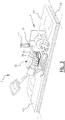
- a spreading and screeding device 2 ( fig. 1 ) has a front construction part 4 on which roller 6, pressing and spreading roller 8 and auger 10 are arranged.
- Construction part 4 is provided movably relative to displacing part 12 of device 2.
- Displacing part 12 is provided with a number of displacing wheels or rollers 14 which rotate a linkage belt 16 with which device 2 is propelled.
- a drive 18 is placed for this purpose on frame 20 of device 2.
- a handle 26 Provided on rear side 22 via arm 24 is a handle 26 with control panel 28 with which a user can control device 2.
- Control panel 28 is provided with an arm 24, for the purpose, among others, of thereby enabling turning, i.e. taking a bend, with device 2.
- the front part ( fig. 2 ) of device 2 has pressing and spreading roller 8 in the form of a worm-like roll, roller 6 and additionally an auger 10.
- pressing and spreading roller 8 in the form of a worm-like roll, roller 6 and additionally an auger 10.
- openings 30 which can be closed if desired with flap 32.
- worm-like pressing and spreading roller 8 is situated a fraction above roller 6 as seen in vertical direction.
- the auger roller is in turn situated above these and is positioned between these two rollers as seen in horizontal direction.
- Front part 4 is connected to rear displaceable part 12 using lifting arm 34 ( fig. 3 ).
- lifting arm 34 fig. 3
- front part 4 can be adjusted in the height A relative to this rear part 12 in the shown embodiment by making use of lifting mechanism 38.
- the whole front part 4 is hereby adjusted in the height relative to rear part 12.
- a possible lateral adjustment B for positioning the front part substantially wholly horizontally or for placing it at a small angle is possible by means of adjusting mechanism 40.
- device 2 has a width of about 76 cm so that device 2 can be moved into a space through a normal door.
- the overall length, including arm 24 and handle 26, is about 2.5 metres.
- Arm 24 can be dispensed with by making use of a remote control (not shown) and a length of about 1.5 metres results.
- the total weight of device 2 is about 250-400 kg.
- screed floor material in the form of mortar 44 is first provided according to the invention on site on ground surface 46.
- Device 2 is then displaced over material 44, whereby material 44 is spread, pressed and levelled in one operation.
- Use is made for this purpose of a separate pressing and spreading roller 8 and a separate roller 6.
- Use is made of the auger 10 for discharging or spreading excess material 44.
- Device 2 is in this way moved over the whole surface of floor 42.
Description
- The invention relates to a spreading and screeding device. Such a device can be used according to the invention to finish a screed floor, particularly a cement screed floor.
-
US 1 731 231 A discloses an apparatus for spreading plastic material. -
DE 19 65 141 A1 discloses a device using screws. -
US 3 515 042 A discloses a concrete vibrating and finishing machine. -
EP 1 865 108 A1 discloses a device for providing a floor surface. - It is known in practice to realize a cement screed floor by placing cement, or sand cement, or mortar on a ground surface. This can optionally take place from a tanker, silo or concrete mixer. The cement is then usually spread manually as well as possible. After this first rough spreading there follows a more precise spreading using a screed. One of the problems occurring here is that it requires much relatively heavy manual work by skilled workers. It is additionally the case that it is usually difficult to maintain a certain quality, and certainly over large floor surfaces. It is likewise known in practice to use auxiliary means in the form of guides which spread the cement together with the screed. It is however also the case here that this is a labour-intensive process involving relatively heavy work and that, even making use of these auxiliary means, it remains difficult to guarantee a constant quality.
- An object of the present invention is to obviate or reduce the above stated problems and to provide a device suitable for realizing a screed floor.
- This object is achieved by the device according to claim 1.
- The displaceable frame achieves that the device is displaceable over the floor where the screed floor has to be realized. This screed floor preferably relates to a cement screed floor, or sand cement screed floor. The frame is provided here with a roller for levelling the screed floor. This roller particularly provides for levelling of the cement for the purpose of thereby realizing a cement screed floor which is even and as level as possible. The frame is operatively connected to a pressing and spreading roller for spreading the screed floor material for the purpose of a good operation of the roller. During use this pressing and spreading roller is placed functionally in front of the roller. This pressing and spreading roller is therefore provided upstream of the roller in the usual forward direction of the frame. The cement is hereby first spread and pressed, or compacted, using this first roller, after which the roller as second roller subsequently levels the floor as a finish. Using the combination of the roller with the pressing and spreading roller the screed floor material can be spread, pressed, or compacted, as well as levelled in one operation. This significantly reduces the number of operations required. It has for instance been found that about 100 m2/hour of floor can be realized with the device according to the invention while, under the same conditions and with the same set requirements for the finished floor, four skilled workers would be necessary for this purpose. In addition, the reproducibility of the screed floor is greatly improved, whereby a constant quality can be provided for the floor.
- A uniform finish is realized by making use of the roller. Making use of a separate pressing and spreading roller realizes a uniform spreading of the material over the floor, which is then pressed down by the roller. A much more even and uniform spreading and pressing is hereby realized than is possible using for instance conventional vibrating devices. Within the context of the present invention, pressing is understood to mean compacting of the material.
- In an advantageous preferred embodiment according to the present invention the pressing and spreading roller comprises a worm-like roller.
- By providing a worm-like roller the function of the pressing, or compacting, and the spreading is combined in a single roller. The eccentric worm roller in the device according to the invention provides for a gentle displacement and spreading of the material which is particularly suitable for viscous material such as mortar. This results in a highly effective device. It has been found that a slightly higher positioning of the pressing and spreading roller in vertical direction over a distance of about 0 to 1 cm relative to the roller has advantageous results. The specific setting depends on, among other factors, the precise composition of the material used. If desired, it is also possible to set the two rollers to the same height.
- In an alternative embodiment the pressing and spreading roller comprises a spiral-shaped roller. Such a spiral-shaped roller is for instance suitable for highly viscous materials for processing, wherein there is more emphasis on the spreading and less on the pressing of the material.
- According to the present invention the device further comprises an auger for spreading screed floor material over the width of the device.
- By providing a separate auger possible excess material arranged for the screed floor which is thrown up by the pressing and spreading roller can be discharged laterally for the purpose of thereby achieving a better spreading of the material over the width of the device. For this purpose the auger is provided above and more preferably at an angle behind the pressing and spreading roller on the device. This auger is also preferably provided, as seen in longitudinal direction of the device, just in front of the roller. It has been found that the most optimal effect of the separate auger is hereby achieved.
- The device according to the invention is provided with at least one opening arranged on the side of the displaceable frame for discharging an excess of screed floor material. By discharging the surplus screed floor material laterally using an auger, this material is spread over the width of the device. Should an excess of screed floor material nevertheless still be present, it can then be discharged from the device with the auger by having this excess material as it were ejected through the opening in lateral direction relative to the device according to the invention.
- An opening is preferably provided on both sides of the device so that, depending on the displacement of the frame relative to a wholly or partially finished screed floor, the material is not ejected onto this wholly or partially finished screed floor, but is conversely set down on the other side where the material still has to be spread and further processed. Preferably provided here are one or more flaps or other sealing means with which the openings can be covered and the material can therefore be prevented from being ejected laterally onto an already finished floor.
- In an advantageous preferred embodiment according to the present invention the device comprises height-adjusting means for adjusting the height of at least the roller and/or the pressing and spreading roller. The setting of the roller and/or the pressing and spreading roller relative to the floor for finishing can be adjusted by providing the height-adjusting means. The two rollers are preferably height-adjustable. In a currently preferred embodiment the two rollers are provided in a separate construction part which is height-adjustable as a unit relative to the other parts of the frame.
- The height-adjusting means preferably comprise a laser. It has been found that making use of a laser results here in a very precise height adjustment, preferably of the roller and the pressing and spreading roller.
- The device according to the invention is preferably further provided with width-adjusting means to enable relative adjustment of the outer ends of the roller and/or the pressing and spreading roller. Being able to adjust the outer ends of one, and preferably both, rollers makes it possible to position them straight, i.e. substantially horizontally. A small angle can also be set if desired.
- In a further advantageous preferred embodiment the displaceable frame comprises a linkage belt.
- Providing a linkage belt achieves that the overall weight of the device is spread over a relatively large surface area of the floor using the links of the linkage belt, whereby the point loads remain limited. The linkage belt is therefore preferably also provided here over a significant part of the width of the device and over a significant part of the length of the device in order to thereby realize a sufficiently large support surface. In a currently preferred embodiment the linkage belt is situated behind the roller, as seen in the usual forward direction of the device. This means that this linkage belt moves over the screed floor which has just been made level.
- Alternatively or in addition to the above stated linkage belt, the displaceable frame comprises at least two belts or tracks for displacing the frame. Turning of the device over the floor is simplified by providing for instance two belts or tracks instead of a single linkage belt over the whole width of the device. It is possible here to drive each track or belt individually so as to further simplify taking a bend or corner. In the above stated variant with one linkage belt over a substantial part of the width, one drive can suffice.
- The device preferably comprises a remote control for controlling the device. By operating in any case the drive of the displaceable frame with the remote control a user does not need to walk over the recently levelled floor. Further point loads over the recently finished floor are hereby prevented. The device can hereby also be shortened to some extent since handles and/or levers are for instance not required. In addition, the weight is hereby also further reduced, whereby point loads are further reduced.
- The invention further relates to a method for manufacturing a floor, comprising of providing a spreading and screeding device as described above.
- Such a method has the same advantages and effects as described above for the device. The method is preferably performed for the purpose of realizing a cement screed floor.
- Further advantages, features and details of the invention are elucidated on the basis of preferred embodiments thereof, wherein reference is made to the accompanying drawing, in which:
-
Fig. 1 shows a side view of the device according to the invention; -
Fig. 2 shows a view of the front side of the device offig. 1 ; and -
Fig. 3 shows a view with partial cross-section of the device offig. 1 . - A spreading and screeding device 2 (
fig. 1 ) has afront construction part 4 on whichroller 6, pressing and spreadingroller 8 andauger 10 are arranged.Construction part 4 is provided movably relative to displacingpart 12 ofdevice 2. Displacingpart 12 is provided with a number of displacing wheels or rollers 14 which rotate alinkage belt 16 with whichdevice 2 is propelled. Adrive 18 is placed for this purpose onframe 20 ofdevice 2. Provided onrear side 22 viaarm 24 is ahandle 26 withcontrol panel 28 with which a user can controldevice 2.Control panel 28 is provided with anarm 24, for the purpose, among others, of thereby enabling turning, i.e. taking a bend, withdevice 2. - The front part (
fig. 2 ) ofdevice 2 has pressing and spreadingroller 8 in the form of a worm-like roll,roller 6 and additionally anauger 10. Provided in the shown embodiment on both sides offront part 4 areopenings 30 which can be closed if desired withflap 32. In the shown embodiment worm-like pressing and spreadingroller 8 is situated a fraction aboveroller 6 as seen in vertical direction. The auger roller is in turn situated above these and is positioned between these two rollers as seen in horizontal direction. -
Front part 4 is connected to reardisplaceable part 12 using lifting arm 34 (fig. 3 ). Using two cylinders 36front part 4 can be adjusted in the height A relative to thisrear part 12 in the shown embodiment by making use of liftingmechanism 38. The wholefront part 4 is hereby adjusted in the height relative torear part 12. A possible lateral adjustment B for positioning the front part substantially wholly horizontally or for placing it at a small angle is possible by means of adjustingmechanism 40. In the shown embodiment use is made of alaser 41 in the adjustment. - In the shown
embodiment device 2 has a width of about 76 cm so thatdevice 2 can be moved into a space through a normal door. The overall length, includingarm 24 and handle 26, is about 2.5 metres.Arm 24 can be dispensed with by making use of a remote control (not shown) and a length of about 1.5 metres results. Depending on the embodiment, the total weight ofdevice 2 is about 250-400 kg. - For the purpose of realizing
floor 42, particularly a screed floor and still more particularly a cement screed floor, screed floor material in the form ofmortar 44 is first provided according to the invention on site onground surface 46.Device 2 is then displaced overmaterial 44, wherebymaterial 44 is spread, pressed and levelled in one operation. Use is made for this purpose of a separate pressing and spreadingroller 8 and aseparate roller 6. Use is made of theauger 10 for discharging or spreadingexcess material 44.Device 2 is in this way moved over the whole surface offloor 42. - The invention is by no means limited to the above described preferred embodiments thereof. The rights sought are defined by the following claims, within the scope of which many modifications can be envisaged. It is thus possible for instance to envisage also using
device 2 according to the invention for pressing or rolling a sand layer, for instance for the purpose of laying clinker paving or paving stones.
Claims (12)
- Spreading and screeding device (2) for manufacturing a screed floor (42), comprising:- a displaceable frame (4);- a roller (6) connected to the frame for levelling the screed floor; and- a pressing and spreading roller (8), connected to the frame and placed functionally in front of the roller during use, for spreading and pressing screed floor material (44), and- an auger (10),characterized in that the auger (10) is connected to the frame (4) and positioned above the pressing and spreading roller (8) for spreading screed floor material over the width of the device, wherein the frame (4) is provided with at least one opening (30) arranged in a side for ejecting an excess of screed floor material laterally through the at least one opening.
- Spreading and screeding device as claimed in claim 1, wherein the auger is further positioned at an angle behind the pressing and spreading roller.
- Spreading and screeding device as claimed in claim 1 or 2, wherein the pressing and spreading roller (8) comprises a worm-like roller.
- Spreading and screeding device as claimed in claim 1 or 2, wherein the pressing and spreading roller (8) comprises a spiral-shaped roller.
- Spreading and screeding device as claimed in one or more of the foregoing claims, further comprising height-adjusting means (38) for adjusting the height of at least the roller and/or the pressing and spreading roller.
- Spreading and screeding device as claimed in claim 5, wherein the height-adjusting means comprise a laser.
- Spreading and screeding device as claimed in one or more of the foregoing claims, further comprising width-adjusting means (40) for relative adjustment in height of the outer ends of the roller and/or the pressing and spreading roller.
- Spreading and screeding device as claimed in one or more of the foregoing claims, wherein the displaceable frame comprises a linkage belt (16).
- Spreading and screeding device as claimed in one or more of the foregoing claims, the displaceable frame of which comprises at least two belts or tracks for the purpose of displacement.
- Spreading and screeding device as claimed in one or more of the foregoing claims, further comprising a remote control for controlling the device.
- Method for manufacturing a floor (42), comprising of providing a spreading and screeding device (2) as claimed in one or more of the foregoing claims.
- Method as claimed in claim 11, wherein the floor comprises a cement screed floor.
Priority Applications (1)
| Application Number | Priority Date | Filing Date | Title |
|---|---|---|---|
| PL12186871T PL2584115T3 (en) | 2011-10-05 | 2012-10-01 | Spreading and screeding device for finishing a screed floor, and method therefor |
Applications Claiming Priority (1)
| Application Number | Priority Date | Filing Date | Title |
|---|---|---|---|
| NL2007541A NL2007541C2 (en) | 2011-10-05 | 2011-10-05 | DIVIDING AND ROWING DEVICE FOR FINISHING A DECK FLOOR AND METHOD FOR IT. |
Publications (3)
| Publication Number | Publication Date |
|---|---|
| EP2584115A2 EP2584115A2 (en) | 2013-04-24 |
| EP2584115A3 EP2584115A3 (en) | 2017-07-19 |
| EP2584115B1 true EP2584115B1 (en) | 2021-01-20 |
Family
ID=46939656
Family Applications (1)
| Application Number | Title | Priority Date | Filing Date |
|---|---|---|---|
| EP12186871.5A Active EP2584115B1 (en) | 2011-10-05 | 2012-10-01 | Spreading and screeding device for finishing a screed floor, and method therefor |
Country Status (3)
| Country | Link |
|---|---|
| EP (1) | EP2584115B1 (en) |
| NL (1) | NL2007541C2 (en) |
| PL (1) | PL2584115T3 (en) |
Families Citing this family (5)
| Publication number | Priority date | Publication date | Assignee | Title |
|---|---|---|---|---|
| CN108824785A (en) * | 2018-06-05 | 2018-11-16 | 佛山市顺德区唯点工业设计有限公司 | A kind of efficient terrace polishing device for building |
| CN110894707A (en) * | 2019-12-29 | 2020-03-20 | 姜小贝 | Bridge deck pavement material leveling machine and implementation method |
| CN113494186A (en) * | 2020-03-19 | 2021-10-12 | 广东博智林机器人有限公司 | Concrete leveling machine and concrete leveling method |
| CN113494037A (en) * | 2020-03-19 | 2021-10-12 | 广东博智林机器人有限公司 | Leveling equipment and leveling device thereof |
| CN113215926A (en) * | 2021-05-26 | 2021-08-06 | 莱州亚通重型装备有限公司 | Concrete paver for underground coal mine |
Citations (1)
| Publication number | Priority date | Publication date | Assignee | Title |
|---|---|---|---|---|
| EP1865108A1 (en) * | 2006-06-09 | 2007-12-12 | Trimmerstar AG | Smoothing and screeding apparatus for surfaces with loose material deposited over it |
Family Cites Families (7)
| Publication number | Priority date | Publication date | Assignee | Title |
|---|---|---|---|---|
| US1731231A (en) * | 1921-06-30 | 1929-10-08 | Catharine R Chenoweth | Method of and apparatus for spreading plastic material |
| US3515042A (en) * | 1968-10-14 | 1970-06-02 | Harold J Austin | Concrete vibrating and finishing machine |
| DE1965141B2 (en) * | 1969-12-27 | 1978-01-19 | Abg-Werke Gmbh, 3250 Hameln | PAVERS |
| SE446893B (en) * | 1984-04-09 | 1986-10-13 | Kjell Yngve Alvarsson | SET AND DEVICE FOR THE EXTENSION OF CONCRETE IN THE CASTING OF LARGE CONCRETE PLATES |
| BE1008262A6 (en) * | 1994-04-19 | 1996-02-27 | Casters Francois | IMPROVEMENTS ON CONCRETE LEVELERS. |
| US5664908A (en) * | 1994-06-20 | 1997-09-09 | Paladeni; Tod | Powered rotary screed |
| DE10116526B4 (en) * | 2001-04-03 | 2004-04-01 | Wacker Construction Equipment Ag | Remote control device for self-propelled tools |
-
2011
- 2011-10-05 NL NL2007541A patent/NL2007541C2/en not_active IP Right Cessation
-
2012
- 2012-10-01 PL PL12186871T patent/PL2584115T3/en unknown
- 2012-10-01 EP EP12186871.5A patent/EP2584115B1/en active Active
Patent Citations (1)
| Publication number | Priority date | Publication date | Assignee | Title |
|---|---|---|---|---|
| EP1865108A1 (en) * | 2006-06-09 | 2007-12-12 | Trimmerstar AG | Smoothing and screeding apparatus for surfaces with loose material deposited over it |
Also Published As
| Publication number | Publication date |
|---|---|
| PL2584115T3 (en) | 2021-08-16 |
| EP2584115A3 (en) | 2017-07-19 |
| EP2584115A2 (en) | 2013-04-24 |
| NL2007541C2 (en) | 2013-04-08 |
Similar Documents
| Publication | Publication Date | Title |
|---|---|---|
| EP2584115B1 (en) | Spreading and screeding device for finishing a screed floor, and method therefor | |
| US8764341B2 (en) | Ground working machine, as well as method for milling soils or traffic areas | |
| US9045871B2 (en) | Paving machine with operator directed saving and recall of machine operating parameters | |
| US4124325A (en) | Asphalt pavement recycling apparatus | |
| US7284929B2 (en) | Paver and method for simultaneously casting several paving material layers | |
| CN108867274B (en) | Paver for paving concrete pavement | |
| US20110002736A1 (en) | Slip form paver | |
| US2380435A (en) | Combination road building machine and concrete spreader | |
| JPH1136220A (en) | Spreading and leveling device for high viscosity pavement material | |
| CN108867273B (en) | Concrete paver | |
| EP0201577B1 (en) | Machine for the production, spreading and packing of dry concrete especially for road construction | |
| US3229601A (en) | Method and apparatus for laying asphalt | |
| CN114197279B (en) | Asphalt concrete pavement paving construction method | |
| US3330188A (en) | Road widener | |
| CN207143684U (en) | A kind of paver of pre- cloth | |
| JP3341173B2 (en) | All-weather concrete casting method and equipment | |
| KR20180016746A (en) | Hybrid spreader having the features of the water sprinkler | |
| JP2000212909A (en) | Laying and levelling device for special pavement material | |
| CN110904789A (en) | Paving smooth cement paving device for mountain road | |
| CN220888210U (en) | Gravel laying device for municipal highway construction | |
| JPS6125848B2 (en) | ||
| JP2007132156A (en) | Screed device of paving machine | |
| JPH08326012A (en) | Concrete pavement system | |
| JPS6125851B2 (en) | ||
| JPS6125850B2 (en) |
Legal Events
| Date | Code | Title | Description |
|---|---|---|---|
| PUAI | Public reference made under article 153(3) epc to a published international application that has entered the european phase |
Free format text: ORIGINAL CODE: 0009012 |
|
| AK | Designated contracting states |
Kind code of ref document: A2 Designated state(s): AL AT BE BG CH CY CZ DE DK EE ES FI FR GB GR HR HU IE IS IT LI LT LU LV MC MK MT NL NO PL PT RO RS SE SI SK SM TR |
|
| AX | Request for extension of the european patent |
Extension state: BA ME |
|
| PUAL | Search report despatched |
Free format text: ORIGINAL CODE: 0009013 |
|
| AK | Designated contracting states |
Kind code of ref document: A3 Designated state(s): AL AT BE BG CH CY CZ DE DK EE ES FI FR GB GR HR HU IE IS IT LI LT LU LV MC MK MT NL NO PL PT RO RS SE SI SK SM TR |
|
| AX | Request for extension of the european patent |
Extension state: BA ME |
|
| RIC1 | Information provided on ipc code assigned before grant |
Ipc: E04F 21/24 20060101AFI20170614BHEP Ipc: E01C 19/26 20060101ALI20170614BHEP Ipc: E01C 19/18 20060101ALI20170614BHEP Ipc: E01C 19/23 20060101ALI20170614BHEP |
|
| STAA | Information on the status of an ep patent application or granted ep patent |
Free format text: STATUS: REQUEST FOR EXAMINATION WAS MADE |
|
| 17P | Request for examination filed |
Effective date: 20180118 |
|
| RBV | Designated contracting states (corrected) |
Designated state(s): AL AT BE BG CH CY CZ DE DK EE ES FI FR GB GR HR HU IE IS IT LI LT LU LV MC MK MT NL NO PL PT RO RS SE SI SK SM TR |
|
| STAA | Information on the status of an ep patent application or granted ep patent |
Free format text: STATUS: EXAMINATION IS IN PROGRESS |
|
| 17Q | First examination report despatched |
Effective date: 20190715 |
|
| GRAP | Despatch of communication of intention to grant a patent |
Free format text: ORIGINAL CODE: EPIDOSNIGR1 |
|
| STAA | Information on the status of an ep patent application or granted ep patent |
Free format text: STATUS: GRANT OF PATENT IS INTENDED |
|
| INTG | Intention to grant announced |
Effective date: 20200915 |
|
| GRAS | Grant fee paid |
Free format text: ORIGINAL CODE: EPIDOSNIGR3 |
|
| GRAA | (expected) grant |
Free format text: ORIGINAL CODE: 0009210 |
|
| STAA | Information on the status of an ep patent application or granted ep patent |
Free format text: STATUS: THE PATENT HAS BEEN GRANTED |
|
| AK | Designated contracting states |
Kind code of ref document: B1 Designated state(s): AL AT BE BG CH CY CZ DE DK EE ES FI FR GB GR HR HU IE IS IT LI LT LU LV MC MK MT NL NO PL PT RO RS SE SI SK SM TR |
|
| REG | Reference to a national code |
Ref country code: GB Ref legal event code: FG4D |
|
| REG | Reference to a national code |
Ref country code: CH Ref legal event code: EP |
|
| REG | Reference to a national code |
Ref country code: DE Ref legal event code: R096 Ref document number: 602012074196 Country of ref document: DE |
|
| REG | Reference to a national code |
Ref country code: AT Ref legal event code: REF Ref document number: 1356529 Country of ref document: AT Kind code of ref document: T Effective date: 20210215 |
|
| REG | Reference to a national code |
Ref country code: IE Ref legal event code: FG4D |
|
| REG | Reference to a national code |
Ref country code: NL Ref legal event code: FP |
|
| REG | Reference to a national code |
Ref country code: LT Ref legal event code: MG9D |
|
| REG | Reference to a national code |
Ref country code: AT Ref legal event code: MK05 Ref document number: 1356529 Country of ref document: AT Kind code of ref document: T Effective date: 20210120 |
|
| PG25 | Lapsed in a contracting state [announced via postgrant information from national office to epo] |
Ref country code: LT Free format text: LAPSE BECAUSE OF FAILURE TO SUBMIT A TRANSLATION OF THE DESCRIPTION OR TO PAY THE FEE WITHIN THE PRESCRIBED TIME-LIMIT Effective date: 20210120 Ref country code: PT Free format text: LAPSE BECAUSE OF FAILURE TO SUBMIT A TRANSLATION OF THE DESCRIPTION OR TO PAY THE FEE WITHIN THE PRESCRIBED TIME-LIMIT Effective date: 20210520 Ref country code: HR Free format text: LAPSE BECAUSE OF FAILURE TO SUBMIT A TRANSLATION OF THE DESCRIPTION OR TO PAY THE FEE WITHIN THE PRESCRIBED TIME-LIMIT Effective date: 20210120 Ref country code: FI Free format text: LAPSE BECAUSE OF FAILURE TO SUBMIT A TRANSLATION OF THE DESCRIPTION OR TO PAY THE FEE WITHIN THE PRESCRIBED TIME-LIMIT Effective date: 20210120 Ref country code: GR Free format text: LAPSE BECAUSE OF FAILURE TO SUBMIT A TRANSLATION OF THE DESCRIPTION OR TO PAY THE FEE WITHIN THE PRESCRIBED TIME-LIMIT Effective date: 20210421 Ref country code: BG Free format text: LAPSE BECAUSE OF FAILURE TO SUBMIT A TRANSLATION OF THE DESCRIPTION OR TO PAY THE FEE WITHIN THE PRESCRIBED TIME-LIMIT Effective date: 20210420 Ref country code: NO Free format text: LAPSE BECAUSE OF FAILURE TO SUBMIT A TRANSLATION OF THE DESCRIPTION OR TO PAY THE FEE WITHIN THE PRESCRIBED TIME-LIMIT Effective date: 20210420 |
|
| PG25 | Lapsed in a contracting state [announced via postgrant information from national office to epo] |
Ref country code: SE Free format text: LAPSE BECAUSE OF FAILURE TO SUBMIT A TRANSLATION OF THE DESCRIPTION OR TO PAY THE FEE WITHIN THE PRESCRIBED TIME-LIMIT Effective date: 20210120 Ref country code: RS Free format text: LAPSE BECAUSE OF FAILURE TO SUBMIT A TRANSLATION OF THE DESCRIPTION OR TO PAY THE FEE WITHIN THE PRESCRIBED TIME-LIMIT Effective date: 20210120 Ref country code: LV Free format text: LAPSE BECAUSE OF FAILURE TO SUBMIT A TRANSLATION OF THE DESCRIPTION OR TO PAY THE FEE WITHIN THE PRESCRIBED TIME-LIMIT Effective date: 20210120 Ref country code: AT Free format text: LAPSE BECAUSE OF FAILURE TO SUBMIT A TRANSLATION OF THE DESCRIPTION OR TO PAY THE FEE WITHIN THE PRESCRIBED TIME-LIMIT Effective date: 20210120 |
|
| PG25 | Lapsed in a contracting state [announced via postgrant information from national office to epo] |
Ref country code: IS Free format text: LAPSE BECAUSE OF FAILURE TO SUBMIT A TRANSLATION OF THE DESCRIPTION OR TO PAY THE FEE WITHIN THE PRESCRIBED TIME-LIMIT Effective date: 20210520 |
|
| REG | Reference to a national code |
Ref country code: DE Ref legal event code: R097 Ref document number: 602012074196 Country of ref document: DE |
|
| PG25 | Lapsed in a contracting state [announced via postgrant information from national office to epo] |
Ref country code: SM Free format text: LAPSE BECAUSE OF FAILURE TO SUBMIT A TRANSLATION OF THE DESCRIPTION OR TO PAY THE FEE WITHIN THE PRESCRIBED TIME-LIMIT Effective date: 20210120 Ref country code: CZ Free format text: LAPSE BECAUSE OF FAILURE TO SUBMIT A TRANSLATION OF THE DESCRIPTION OR TO PAY THE FEE WITHIN THE PRESCRIBED TIME-LIMIT Effective date: 20210120 Ref country code: EE Free format text: LAPSE BECAUSE OF FAILURE TO SUBMIT A TRANSLATION OF THE DESCRIPTION OR TO PAY THE FEE WITHIN THE PRESCRIBED TIME-LIMIT Effective date: 20210120 |
|
| PLBE | No opposition filed within time limit |
Free format text: ORIGINAL CODE: 0009261 |
|
| STAA | Information on the status of an ep patent application or granted ep patent |
Free format text: STATUS: NO OPPOSITION FILED WITHIN TIME LIMIT |
|
| PG25 | Lapsed in a contracting state [announced via postgrant information from national office to epo] |
Ref country code: DK Free format text: LAPSE BECAUSE OF FAILURE TO SUBMIT A TRANSLATION OF THE DESCRIPTION OR TO PAY THE FEE WITHIN THE PRESCRIBED TIME-LIMIT Effective date: 20210120 Ref country code: ES Free format text: LAPSE BECAUSE OF FAILURE TO SUBMIT A TRANSLATION OF THE DESCRIPTION OR TO PAY THE FEE WITHIN THE PRESCRIBED TIME-LIMIT Effective date: 20210120 Ref country code: SK Free format text: LAPSE BECAUSE OF FAILURE TO SUBMIT A TRANSLATION OF THE DESCRIPTION OR TO PAY THE FEE WITHIN THE PRESCRIBED TIME-LIMIT Effective date: 20210120 Ref country code: RO Free format text: LAPSE BECAUSE OF FAILURE TO SUBMIT A TRANSLATION OF THE DESCRIPTION OR TO PAY THE FEE WITHIN THE PRESCRIBED TIME-LIMIT Effective date: 20210120 |
|
| 26N | No opposition filed |
Effective date: 20211021 |
|
| PG25 | Lapsed in a contracting state [announced via postgrant information from national office to epo] |
Ref country code: AL Free format text: LAPSE BECAUSE OF FAILURE TO SUBMIT A TRANSLATION OF THE DESCRIPTION OR TO PAY THE FEE WITHIN THE PRESCRIBED TIME-LIMIT Effective date: 20210120 |
|
| PG25 | Lapsed in a contracting state [announced via postgrant information from national office to epo] |
Ref country code: SI Free format text: LAPSE BECAUSE OF FAILURE TO SUBMIT A TRANSLATION OF THE DESCRIPTION OR TO PAY THE FEE WITHIN THE PRESCRIBED TIME-LIMIT Effective date: 20210120 |
|
| REG | Reference to a national code |
Ref country code: CH Ref legal event code: PL |
|
| PG25 | Lapsed in a contracting state [announced via postgrant information from national office to epo] |
Ref country code: IS Free format text: LAPSE BECAUSE OF FAILURE TO SUBMIT A TRANSLATION OF THE DESCRIPTION OR TO PAY THE FEE WITHIN THE PRESCRIBED TIME-LIMIT Effective date: 20210520 |
|
| GBPC | Gb: european patent ceased through non-payment of renewal fee |
Effective date: 20211001 |
|
| PG25 | Lapsed in a contracting state [announced via postgrant information from national office to epo] |
Ref country code: MC Free format text: LAPSE BECAUSE OF FAILURE TO SUBMIT A TRANSLATION OF THE DESCRIPTION OR TO PAY THE FEE WITHIN THE PRESCRIBED TIME-LIMIT Effective date: 20210120 |
|
| PG25 | Lapsed in a contracting state [announced via postgrant information from national office to epo] |
Ref country code: LU Free format text: LAPSE BECAUSE OF NON-PAYMENT OF DUE FEES Effective date: 20211001 Ref country code: GB Free format text: LAPSE BECAUSE OF NON-PAYMENT OF DUE FEES Effective date: 20211001 |
|
| PG25 | Lapsed in a contracting state [announced via postgrant information from national office to epo] |
Ref country code: LI Free format text: LAPSE BECAUSE OF NON-PAYMENT OF DUE FEES Effective date: 20211031 Ref country code: CH Free format text: LAPSE BECAUSE OF NON-PAYMENT OF DUE FEES Effective date: 20211031 |
|
| PG25 | Lapsed in a contracting state [announced via postgrant information from national office to epo] |
Ref country code: IE Free format text: LAPSE BECAUSE OF NON-PAYMENT OF DUE FEES Effective date: 20211001 |
|
| PGFP | Annual fee paid to national office [announced via postgrant information from national office to epo] |
Ref country code: BE Payment date: 20221027 Year of fee payment: 11 |
|
| PG25 | Lapsed in a contracting state [announced via postgrant information from national office to epo] |
Ref country code: HU Free format text: LAPSE BECAUSE OF FAILURE TO SUBMIT A TRANSLATION OF THE DESCRIPTION OR TO PAY THE FEE WITHIN THE PRESCRIBED TIME-LIMIT; INVALID AB INITIO Effective date: 20121001 Ref country code: CY Free format text: LAPSE BECAUSE OF FAILURE TO SUBMIT A TRANSLATION OF THE DESCRIPTION OR TO PAY THE FEE WITHIN THE PRESCRIBED TIME-LIMIT Effective date: 20210120 |
|
| PGFP | Annual fee paid to national office [announced via postgrant information from national office to epo] |
Ref country code: PL Payment date: 20230926 Year of fee payment: 12 Ref country code: NL Payment date: 20231026 Year of fee payment: 12 |
|
| PGFP | Annual fee paid to national office [announced via postgrant information from national office to epo] |
Ref country code: IT Payment date: 20231023 Year of fee payment: 12 Ref country code: FR Payment date: 20231025 Year of fee payment: 12 Ref country code: DE Payment date: 20231027 Year of fee payment: 12 |
|
| PGFP | Annual fee paid to national office [announced via postgrant information from national office to epo] |
Ref country code: BE Payment date: 20231027 Year of fee payment: 12 |