EP2583870A1 - Piston-cylinder unit and personal safety system with such a piston-cylinder unit integrated into the vehicle - Google Patents
Piston-cylinder unit and personal safety system with such a piston-cylinder unit integrated into the vehicle Download PDFInfo
- Publication number
- EP2583870A1 EP2583870A1 EP12004728.7A EP12004728A EP2583870A1 EP 2583870 A1 EP2583870 A1 EP 2583870A1 EP 12004728 A EP12004728 A EP 12004728A EP 2583870 A1 EP2583870 A1 EP 2583870A1
- Authority
- EP
- European Patent Office
- Prior art keywords
- piston
- cylinder
- cylinder unit
- closure cap
- projection
- Prior art date
- Legal status (The legal status is an assumption and is not a legal conclusion. Google has not performed a legal analysis and makes no representation as to the accuracy of the status listed.)
- Granted
Links
Images
Classifications
-
- B—PERFORMING OPERATIONS; TRANSPORTING
- B60—VEHICLES IN GENERAL
- B60R—VEHICLES, VEHICLE FITTINGS, OR VEHICLE PARTS, NOT OTHERWISE PROVIDED FOR
- B60R21/00—Arrangements or fittings on vehicles for protecting or preventing injuries to occupants or pedestrians in case of accidents or other traffic risks
- B60R21/34—Protecting non-occupants of a vehicle, e.g. pedestrians
- B60R21/38—Protecting non-occupants of a vehicle, e.g. pedestrians using means for lifting bonnets
-
- B—PERFORMING OPERATIONS; TRANSPORTING
- B60—VEHICLES IN GENERAL
- B60R—VEHICLES, VEHICLE FITTINGS, OR VEHICLE PARTS, NOT OTHERWISE PROVIDED FOR
- B60R22/00—Safety belts or body harnesses in vehicles
- B60R22/18—Anchoring devices
- B60R22/195—Anchoring devices with means to tension the belt in an emergency, e.g. means of the through-anchor or splitted reel type
- B60R22/1954—Anchoring devices with means to tension the belt in an emergency, e.g. means of the through-anchor or splitted reel type characterised by fluid actuators, e.g. pyrotechnic gas generators
-
- F—MECHANICAL ENGINEERING; LIGHTING; HEATING; WEAPONS; BLASTING
- F15—FLUID-PRESSURE ACTUATORS; HYDRAULICS OR PNEUMATICS IN GENERAL
- F15B—SYSTEMS ACTING BY MEANS OF FLUIDS IN GENERAL; FLUID-PRESSURE ACTUATORS, e.g. SERVOMOTORS; DETAILS OF FLUID-PRESSURE SYSTEMS, NOT OTHERWISE PROVIDED FOR
- F15B15/00—Fluid-actuated devices for displacing a member from one position to another; Gearing associated therewith
- F15B15/08—Characterised by the construction of the motor unit
- F15B15/14—Characterised by the construction of the motor unit of the straight-cylinder type
- F15B15/1423—Component parts; Constructional details
- F15B15/1438—Cylinder to end cap assemblies
-
- F—MECHANICAL ENGINEERING; LIGHTING; HEATING; WEAPONS; BLASTING
- F15—FLUID-PRESSURE ACTUATORS; HYDRAULICS OR PNEUMATICS IN GENERAL
- F15B—SYSTEMS ACTING BY MEANS OF FLUIDS IN GENERAL; FLUID-PRESSURE ACTUATORS, e.g. SERVOMOTORS; DETAILS OF FLUID-PRESSURE SYSTEMS, NOT OTHERWISE PROVIDED FOR
- F15B15/00—Fluid-actuated devices for displacing a member from one position to another; Gearing associated therewith
- F15B15/19—Pyrotechnical actuators
Definitions
- the invention relates to a piston-cylinder unit with a cylinder and a displaceable in an axial direction from an initial position to an end position in the cylinder mounted piston, wherein the cylinder at a front end side has an outlet opening and the piston in its end position through this outlet opening extends.
- the invention relates to a vehicle-integrated personal safety system with such a piston-cylinder unit as a drive unit.
- Piston-cylinder units are used in many areas of vehicle safety technology.
- a field of application for example, systems for actively improving the safety of passers-by, such. B. pedestrians or cyclists.
- a piston-cylinder unit is used to dampen the impact of a pedestrian on the bonnet of a vehicle by increasing the possible deformation path of the bonnet.
- the bonnet of the vehicle is raised by a defined distance just before the impact of passers-by, which can be done by a piston-cylinder unit.
- piston-cylinder units are used in belt tensioners. They serve to limit the forward displacement of the occupants by tightening the seat belt.
- Another field of application for piston-cylinder units are convertible vehicles, which are provided with an extendable roll bar. Such a roll bar is extended by means of a piston-cylinder unit when the convertible vehicle rolls over.
- the piston-cylinder unit according to the invention has a cylinder and a piston displaceably mounted in an axial direction from an initial position to an end position in the cylinder, wherein the cylinder has an outlet opening at a front end side and the piston extends in its end position through this outlet opening.
- the outlet opening of the cylinder is provided with a closure cap, preferably closed by it, which rests in the initial position on the piston, preferably at one of the outlet opening of the cylinder facing the front end portion of the piston.
- the cap positions the piston in the axial and / or radial direction within the cylinder and causes it to wobble in the cylinder, for example, during operation of the vehicle and generate rattling noises.
- This allows the piston to be accommodated in the cylinder in an easily displaceable manner, because the piston is positioned in the initial position through the cap.
- the piston is e.g. at a stop of the cylinder.
- the closure cap further constitutes a sealing element by shielding the interior of the cylinder from undesired environmental influences, such as e.g. Moisture, dirt particles, seals against the surrounding area of the cylinder.
- the cap should press in the initial position with bias against the piston.
- the attachment of the cap on the cylinder takes place in particular by the cap rests with its radial inner side at least partially on an outer side of the cylinder jacket.
- the cap rests with its radial inner side at least partially on an outer side of the cylinder jacket.
- the cap is attached to the cylinder so that it can be released by displacing the piston from the cylinder; i.e. upon actuation of the piston-cylinder unit, the cap may advantageously be non-destructive, i. as a whole, be pushed away from the cylinder by the extending piston. It is also conceivable that the cap is not torn off as a whole; i.e. that portions of the cap are separated during or after actuation of the piston-cylinder unit separately from each other from the cylinder, or still remain attached to the cylinder.
- the preferred embodiment of the invention provides a pyrotechnic drive provided in the unit for moving the piston.
- a defined release force and a defined position of the closure cap can be achieved in the piston-cylinder unit according to the invention, since it can be fastened against axial displacement, in particular form-fitting, to the cylinder, e.g. by a locking connection.
- the positive locking allows exact positioning of the cap relative to the cylinder.
- detent connection and bias of the piston ensures that the cap itself is pressed axially outwards, so that the position of the cap is clearly specified.
- the cap can also be held by friction on the cylinder. Consequently, the piston arranged in the interior of the cylinder can be placed under a defined preload, whereby a likewise defined adhesion between the cap and the piston is achieved.
- the piston is in its initial position, so by the positive and / or frictional connection between the piston and cap, an undesired movement of the piston in the cylinder, for example during operation of a vehicle, in which the piston-cylinder unit is integrated, effectively minimized or be avoided.
- a collar of the closure cap which encloses the outer surface of the cylinder in the initial position, on its inside an undercut, which cooperates positively with a present on the lateral surface of the cylinder latching projection.
- the collar of the closure cap which encloses in the initial position, the lateral surface of the cylinder, on its inside a latching projection which cooperates positively with a groove provided in the lateral surface of the cylinder groove.
- the undercut, the latching projection and / or the groove are designed to run radially. If the locking projections, the undercut and the groove are designed to run radially around, then the closure cap can be placed in an arbitrarily rotated position with respect to the axial direction. This represents a further simplification.
- the axial end of the cylinder and / or the collar may also be slotted, preferably in the axial direction (A), so as to provide elastic finger-shaped portions which facilitate latching of the closure cap and the front face of the cylinder.
- the seat and the position of the closure cap are defined on the cylinder by the positions of the corresponding latching projections and the undercut or the groove.
- the already simplified manufacturing process is subject only to the predetermined by the corresponding components manufacturing tolerances.
- Other tolerances such as may occur when pressing a cap, do not occur.
- the closure cap comprises an end wall which, in the starting position, opposes the outlet opening and closes it.
- the end wall is transverse, further preferably oriented perpendicular to the axial direction.
- the end wall has on the side facing the outlet opening at least one projection, e.g. in the form of a bead which abuts, in particular in the initial position of the closure cap, against a front end region of the piston in its starting position, in particular under prestressing.
- the front end of the piston is positioned in the axial direction and / or radial direction.
- the preferred embodiment provides that the at least one projection rests on an inclined surface on the front end region, so that a centering of the piston end takes place.
- the cap or the projection is elastically or plastically deformable, wherein the present in the attached state of the closure cap is made to the front end of the piston under plastic or elastic deformation of the projection.
- the projection is radially circumferential and continuous, but it can, for example, to save material, even a partially configured bead are used.
- the end wall of the closure cap is formed on its outside facing away from the outlet opening so that it has an at least partially convex outer contour.
- This outer contour can e.g. be spherical.
- Such an outer contour can prevent a user of the piston-cylinder unit from turning them down in a possibly unfavorable position, for example the closure cap pointing downwards, in the direction of a solid ground.
- the cap-side end of the cylinder is provided with an outside shoulder, on the outside of the cap is placed.
- the end position of the piston is defined by a stop present on the cylinder.
- the piston-cylinder unit may have a pyrotechnic drive for moving the piston, wherein the pyrotechnic drive preferably comprises a combustion chamber with pyrotechnic material and / or an igniter.
- a vehicle-integrated personal safety system with a piston-cylinder unit according to one or more of the aforementioned embodiments is specified as a drive unit.
- the vehicle-integrated personal safety system has an electronic control unit, by means of which the piston-cylinder unit can be activated in the presence of a triggering situation.
- the piston-cylinder unit according to the invention also apply to the vehicle-integrated personal safety system and therefore require no further explanation.
- the vehicle-integrated personal safety system may comprise a positioning system for an engine hood and / or a roll bar of a vehicle, wherein, as already described, in the case of the installation system for a hood, the hood of the vehicle can be raised by a defined distance to a possible deformation of the To increase the bonnet in an impact of a passer on the hood and in the case of the roll bar such a roll bar can be extended when the vehicle, preferably a convertible vehicle, overturns.
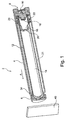
- FIG. 1 shows an embodiment of a piston-cylinder unit 2 of a vehicle-integrated personal safety system in a simplified perspective sectional view.
- the piston-cylinder unit 2 comprises a cylinder 4, which has an outlet opening at its front end, which is closed by a closure cap 6.
- a connector receptacle 8 is provided, which has pins 10 as a contacts of a detonator 18.
- the piston 12 is closed on one side and comprises in its interior an expansion chamber 14 for receiving pressurized gas.
- the pressure necessary to extend the piston 12 is generated pyrotechnically in the illustrated piston-cylinder unit 2.
- the pyrotechnic drive comprises a combustion chamber 16, which projects into the expansion chamber 14 of the piston 12.
- a combustion chamber 16 In the combustion chamber 16 is pyrotechnic material or a compressed gas cartridge.
- the pyrotechnic material can be activated by means of the igniter 18.
- the expansion chamber 14 is sealed from an annular space 21 between the inside of the cylinder 4 and the outside of the piston 12 spaced therefrom by a seal which has a seal carrier 22 formed as an annular component and an O-ring 24 inserted in a radial circumferential groove of this seal carrier 22 includes.
- a seal carrier 22 formed as an annular component and an O-ring 24 inserted in a radial circumferential groove of this seal carrier 22 includes.
- the seal carrier 22 abuts against the cylinder-side stop 34, whereby a deformation region present in the igniter-side end of the piston 12 can be plastically or elastically deformed and the movement of the cylinder 4 decelerated.
- the stopper 34 is formed by a peripheral shoulder of the cylinder 4 at its front end.
- a pedestrian protection system is raised by the extension of the piston 12, for example, a hood 40 of a vehicle by a defined distance, so that upon impact of a person a corresponding crumple zone by deformation of the hood 40 is available and prevents or mitigated contact of the person with the underlying engine block can be.
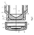
- FIG. 2 shows a simplified detailed sectional view of the piston-cylinder unit 2 from FIG. 1 in the region of the outlet opening 32 of the cylinder 4th
- the piston 12 is in its initial position, in which its front end 36 is positioned slightly behind the outlet opening 32 is set back.
- a latching projection 38 is present on its outer circumferential surface, which is preferably designed to run radially. More generally, the locking projection 38 is located in the region of the outlet opening 32.
- the closure cap 6 comprises an end wall 46, which extends transversely, preferably substantially perpendicular to the axial direction A, and to which a radially encircling collar 44 adjoins.
- the collar 44 surrounds the outer surface of the cylinder 4, and the end wall 46 closes the outlet opening 32.
- the collar 44 preferably by means of a press fit, form a sealing connection to the outer circumferential surface of the cylinder 4.
- the undercut 42 is provided in an inner side of the collar 44 and is preferably located in a region of the collar 44 which adjoins the end wall 46.
- One of the outlet opening 32 facing away from the outside of the end wall 46 is preferably convex, further preferably spherical. In this way, it is to be prevented that a user places the piston-cylinder unit 2 in a possible unfavorable position, for example the closure cap pointing down, in the direction of a solid ground, standing on the end wall 46.
- One of the outlet opening 32 (viewed in the assembled state of the closure cap 6) facing inside of the closure cap 6 is provided with a projection 48.
- This projection 48 is preferably made of a plastically and / or elastically deformable material and occurs in the assembled state of the closure cap 6 with the front end portion 36 of the piston 12 under bias in contact.
- a biasing force can be introduced into the piston 12.
- the contact surface of the projection 48 is an inclined surface, here a rounded edge of the piston end.
- the piston 12 is held by the projection 48 in its intended starting position.
- a radial clearance possibly present between the outside of the piston 12 and the inside of the cylinder 4 can be accepted since the piston 12 is held by the closure cap 6 via the bead 48. It is advantageous that the closure cap 6 is held positively over its undercut 42 on the locking projection 38 of the cylinder 4 and therefore has a high withdrawal force.
- the closure cap 6 can be provided with a latching projection which engages in a matching groove which is present in the outer circumferential surface of the cylinder 4.
- a latching projection is preferably arranged a region of the end of the collar 44, which faces away from the cover 46.
- the cap 6 is in particular made of plastic.
- the shoulder at the front end of the cylinder forms at its radially inner surface a guide surface for the front end of the piston 12, which lies in the starting position in the region of the shoulder.
Abstract
Description
Die Erfindung betrifft eine Kolben-Zylinder-Einheit mit einem Zylinder und einem in einer Axialrichtung aus einer Ausgangsstellung in eine Endstellung verschiebbar in dem Zylinder gelagerten Kolben, wobei der Zylinder an einer vorderen Stirnseite eine Austrittsöffnung aufweist und sich der Kolben in seiner Endstellung durch diese Austrittsöffnung erstreckt. Außerdem betrifft die Erfindung ein fahrzeugintegrierbares Personensicherheitssystem mit einer solchen Kolben-Zylinder-Einheit als Antriebseinheit.The invention relates to a piston-cylinder unit with a cylinder and a displaceable in an axial direction from an initial position to an end position in the cylinder mounted piston, wherein the cylinder at a front end side has an outlet opening and the piston in its end position through this outlet opening extends. In addition, the invention relates to a vehicle-integrated personal safety system with such a piston-cylinder unit as a drive unit.
Kolben-Zylinder-Einheiten werden in vielen Bereichen der Fahrzeugsicherheitstechnik eingesetzt. Ein Einsatzgebiet sind beispielsweise Systeme zur aktiven Verbesserung der Sicherheit von Passanten, wie z. B. Fußgängern oder Radfahrern. In diesem Zusammenhang wird eine Kolben-Zylinder-Einheit verwendet, um den Aufprall eines Passanten auf die Motorhaube eines Fahrzeugs zu dämpfen, indem der mögliche Deformationsweg der Motorhaube erhöht wird. Zu diesem Zweck wird kurz vor dem Aufprall des Passanten die Motorhaube des Fahrzeugs um eine definierte Wegstrecke angehoben, was durch eine Kolben-Zylinder-Einheit erfolgen kann. Außerdem werden Kolben-Zylinder-Einheiten bei Gurtstraffern eingesetzt. Sie dienen dazu, die Vorverlagerung der Insassen durch eine Straffung des Sicherheitsgurtes zu begrenzen. Ein weiteres Einsatzgebiet für Kolben-Zylinder-Einheiten sind Cabrio-Fahrzeuge, welche mit einem ausfahrbaren Überrollbügel versehen sind. Ein solcher Überrollbügel wird mittels einer Kolben-Zylinder-Einheit ausgefahren, wenn sich das Cabrio-Fahrzeug überschlägt.Piston-cylinder units are used in many areas of vehicle safety technology. A field of application, for example, systems for actively improving the safety of passers-by, such. B. pedestrians or cyclists. In this connection, a piston-cylinder unit is used to dampen the impact of a pedestrian on the bonnet of a vehicle by increasing the possible deformation path of the bonnet. For this purpose, the bonnet of the vehicle is raised by a defined distance just before the impact of passers-by, which can be done by a piston-cylinder unit. In addition, piston-cylinder units are used in belt tensioners. They serve to limit the forward displacement of the occupants by tightening the seat belt. Another field of application for piston-cylinder units are convertible vehicles, which are provided with an extendable roll bar. Such a roll bar is extended by means of a piston-cylinder unit when the convertible vehicle rolls over.
Bei aus dem Stand der Technik bekannten Kolben-Zylinder-Einheiten tritt der Kolben, wenn dieser in Richtung einer Axialrichtung der Kolben-Zylinder-Einheit aus seiner Ausgangsstellung in eine Endstellung verschoben wird, durch eine in dem Zylinder vorhandene und an dessen vorderer Stirnseite angeordnete Austrittsöffnung hindurch. In der Ausgangsstellung des Kolbens befindet sich in der Regel dessen vorderes Ende innerhalb des Zylinders und somit von der vorderen Stirnseite des Zylinders her betrachtet hinter der Austrittsöffnung, wobei auch denkbar ist, dass das vordere Ende des Kolbens in der Ausgangsstellung schon teilweise durch die Austrittsöffnung hindurch ragt. In diesem Zustand der Ausgangsstellung der Kolben-Zylinder-Einheit ist die Austrittsöffnung des Zylinders mit einer Verschlusskappe, welche vorzugsweise aus Kunststoff hergestellt ist, verschlossen. Eine solche Verschlusskappe wird üblicherweise auf das die Austrittsöffnung umfassende Ende des Zylinders gepresst.In known from the prior art piston-cylinder units, when the piston is displaced in the direction of an axial direction of the piston-cylinder unit from its initial position to an end position, passes through an existing in the cylinder and arranged on the front end side Outlet opening through. In the initial position of the piston is usually the front end within the cylinder and thus viewed from the front end side of the cylinder behind the outlet opening, wherein it is also conceivable that the front end of the piston in the initial position already partially through the outlet opening protrudes. In this state, the starting position of the piston-cylinder unit, the outlet opening of the cylinder is closed with a closure cap, which is preferably made of plastic. Such a closure cap is usually pressed onto the end of the cylinder which encloses the outlet opening.
Es ist Aufgabe der Erfindung, eine verbesserte Kolben-Zylinder-Einheit sowie ein verbessertes fahrzeugintegrierbares Personensicherheitssystem mit einer solchen Kolben-Zylinder-Einheit anzugeben, bei der der Kolben eine über die Lebenszeit der Kolben-Zylinder-Einheit hinweg eine reproduzierbare Ausgangsstellung hat.It is an object of the invention to provide an improved piston-cylinder unit and an improved vehicle-integrated personal safety system with such a piston-cylinder unit in which the piston has a reproducible starting position over the lifetime of the piston-cylinder unit.
Die erfindungsgemäße Kolben-Zylinder-Einheit hat einen Zylinder und einen in einer Axialrichtung aus einer Ausgangsstellung in eine Endstellung verschiebbar in dem Zylinder gelagerten Kolben, wobei der Zylinder an einer vorderen Stirnseite eine Austrittsöffnung aufweist und sich der Kolben in seiner Endstellung durch diese Austrittsöffnung erstreckt. Die Austrittsöffnung des Zylinders ist mit einer Verschlusskappe versehen, vorzugsweise durch sie verschlossen, welche in der Ausgangsstellung an dem Kolben, vorzugsweise an einem der Austrittsöffnung des Zylinders zugewandten vorderen Endbereich des Kolbens, anliegt.The piston-cylinder unit according to the invention has a cylinder and a piston displaceably mounted in an axial direction from an initial position to an end position in the cylinder, wherein the cylinder has an outlet opening at a front end side and the piston extends in its end position through this outlet opening. The outlet opening of the cylinder is provided with a closure cap, preferably closed by it, which rests in the initial position on the piston, preferably at one of the outlet opening of the cylinder facing the front end portion of the piston.
Die Verschlusskappe positioniert den Kolben in Axial- und/oder Radialrichtung innerhalb des Zylinders und führt dazu, dass dieser im Zylinder nicht beispielsweise während des Betriebs des Fahrzeugs wackeln und Klappergeräusche erzeugen kann. Damit lässt sich der Kolben leicht verschieblich im Zylinder unterbringen, denn der Kolben wird in der Ausgangsstellung durch die Kappe positioniert. In Richtung zum entgegengesetzten Ende liegt der Kolben z.B. an einem Anschlag des Zylinders an. Die Verschlusskappe stellt weiterhin ein Dichtelement dar, indem sie den Innenbereich des Zylinders vor ungewünschten Umwelteinflüssen, wie z.B. Feuchtigkeit, Schmutzpartikel, gegen den Umgebungsbereich des Zylinders abdichtet.The cap positions the piston in the axial and / or radial direction within the cylinder and causes it to wobble in the cylinder, for example, during operation of the vehicle and generate rattling noises. This allows the piston to be accommodated in the cylinder in an easily displaceable manner, because the piston is positioned in the initial position through the cap. Towards the opposite end the piston is e.g. at a stop of the cylinder. The closure cap further constitutes a sealing element by shielding the interior of the cylinder from undesired environmental influences, such as e.g. Moisture, dirt particles, seals against the surrounding area of the cylinder.
Um Toleranzen auszugleichen sollte die Verschlusskappe in der Ausgangsstellung mit Vorspannung gegen den Kolben drücken.To compensate for tolerances, the cap should press in the initial position with bias against the piston.
Die Befestigung der Kappe am Zylinder erfolgt insbesondere indem die Kappe mit ihrer radialen Innenseite zumindest teilweise an einer Außenseite des Zylindermantels anliegt. Natürlich wäre es auch möglich, die Kappe nicht auf den Zylinder aufzustecken, sondern in den Zylinder als Verschluss einzustecken.The attachment of the cap on the cylinder takes place in particular by the cap rests with its radial inner side at least partially on an outer side of the cylinder jacket. Of course, it would also be possible not aufzustecken the cap on the cylinder, but to plug in the cylinder as a closure.
Insbesondere ist die Kappe so am Zylinder befestigt, dass sie durch Verschieben des Kolbens vom Zylinder lösbar ist; d.h. bei Betätigen der Kolben-Zylinder-Einheit kann die Kappe, vorteilhaft zerstörungsfrei, d.h. als Ganzes, von dem Zylinder durch den ausfahrenden Kolben weggestoßen werden. Es ist auch denkbar, dass dabei die Kappe nicht als Ganzes abgerissen wird; d.h. dass Teilbereiche der Kappe bei bzw. nach Betätigen der Kolben-Zylindereinheit getrennt voneinander von dem Zylinder abgelöst werden, bzw. noch am Zylinder befestigt bleiben.In particular, the cap is attached to the cylinder so that it can be released by displacing the piston from the cylinder; i.e. upon actuation of the piston-cylinder unit, the cap may advantageously be non-destructive, i. as a whole, be pushed away from the cylinder by the extending piston. It is also conceivable that the cap is not torn off as a whole; i.e. that portions of the cap are separated during or after actuation of the piston-cylinder unit separately from each other from the cylinder, or still remain attached to the cylinder.
Die bevorzugte Ausführungsform der Erfindung sieht einen in der Einheit vorgesehenen pyrotechnischen Antrieb zur Bewegung des Kolbens vor.The preferred embodiment of the invention provides a pyrotechnic drive provided in the unit for moving the piston.
Vorteilhaft kann bei der erfindungsgemäßen Kolben-Zylinder-Einheit eine definierte Lösekraft und eine definierte Position der Verschlusskappe erreicht werden, da diese gegen axiales Verschieben, insbesondere formschlüssig, an dem Zylinder befestigt sein kann, z.B. durch eine Rastverbindung. Der Formschluss erlaubt eine exakte Positionierung der Kappe relativ zum Zylinder.Advantageously, a defined release force and a defined position of the closure cap can be achieved in the piston-cylinder unit according to the invention, since it can be fastened against axial displacement, in particular form-fitting, to the cylinder, e.g. by a locking connection. The positive locking allows exact positioning of the cap relative to the cylinder.
Die Kombination aus Rastverbindung und Vorspannung des Kolbens sorgt dafür, dass die Kappe selbst axial nach außen gedrückt ist, so dass die Position der Kappe klar vorgegeben ist.The combination of detent connection and bias of the piston ensures that the cap itself is pressed axially outwards, so that the position of the cap is clearly specified.
Selbstverständlich kann die Verschlusskappe zusätzlich auch reibschlüssig an dem Zylinder gehalten sein. Folglich kann der im Inneren des Zylinders angeordnete Kolben unter eine definierte Vorspannung gesetzt werden, wodurch ein ebenfalls definierter Kraftschluss zwischen der Verschlusskappe und dem Kolben zustande kommt. Befindet sich der Kolben in seiner Ausgangsstellung, so kann durch den Form- und/oder Kraftschluss zwischen Kolben und Verschlusskappe eine ungewünschte Bewegung des Kolbens in dem Zylinder, beispielsweise während des Betriebs eines Fahrzeugs, in das die Kolben-Zylindereinheit integriert ist, wirkungsvoll minimiert oder vermieden werden.Of course, the cap can also be held by friction on the cylinder. Consequently, the piston arranged in the interior of the cylinder can be placed under a defined preload, whereby a likewise defined adhesion between the cap and the piston is achieved. The piston is in its initial position, so by the positive and / or frictional connection between the piston and cap, an undesired movement of the piston in the cylinder, for example during operation of a vehicle, in which the piston-cylinder unit is integrated, effectively minimized or be avoided.
Gemäß einer weiteren Ausführungsform weist ein Kragen der Verschlusskappe, der in der Ausgangsstellung die Mantelfläche des Zylinders umschließt, auf seiner Innenseite einen Hinterschnitt auf, der mit einem auf der Mantelfläche des Zylinders vorhandenen Rastvorsprung formschlüssig zusammenwirkt. Gemäß einer alternativen Ausführungsform weist der Kragen der Verschlusskappe, der in der Ausgangsstellung die Mantelfläche des Zylinders umschließt, auf seiner Innenseite einen Rastvorsprung auf, welcher mit einer in die Mantelfläche des Zylinders vorgesehenen Nut formschlüssig zusammenwirkt.According to a further embodiment, a collar of the closure cap, which encloses the outer surface of the cylinder in the initial position, on its inside an undercut, which cooperates positively with a present on the lateral surface of the cylinder latching projection. According to an alternative embodiment, the collar of the closure cap, which encloses in the initial position, the lateral surface of the cylinder, on its inside a latching projection which cooperates positively with a groove provided in the lateral surface of the cylinder groove.
Bevorzugt sind der Hinterschnitt, der Rastvorsprung und/oder die Nut radial umlaufend ausgeführt. Sind die Rastvorsprünge, der Hinterschnitt und die Nut radial umlaufend ausgeführt, so kann die Verschlusskappe in einer bezüglich der Axialrichtung beliebig gedrehten Position aufgesetzt werden. Dies stellt eine weitere Vereinfachung dar.Preferably, the undercut, the latching projection and / or the groove are designed to run radially. If the locking projections, the undercut and the groove are designed to run radially around, then the closure cap can be placed in an arbitrarily rotated position with respect to the axial direction. This represents a further simplification.
Das axiale Ende des Zylinders und/oder der Kragen können auch, vorzugsweise in Axialrichtung (A), geschlitzt sein, so dass sich elastische fingerförmige Abschnitte ergeben, die ein Verrasten von Verschlusskappe und der vorderen Stirnseite des Zylinders erleichtern.The axial end of the cylinder and / or the collar may also be slotted, preferably in the axial direction (A), so as to provide elastic finger-shaped portions which facilitate latching of the closure cap and the front face of the cylinder.
Auf ein Verpressen der Verschlusskappe kann bei Vorsehen einer Rastverbindung verzichtet werden, was einen Kostenvorteil bei der Montage der Kolben-Zylinder-Einheiten darstellt. Außerdem sind der Sitz und die Position der Verschlusskappe auf dem Zylinder durch die Positionen der entsprechenden Rastvorsprünge sowie des Hinterschnitts bzw. der Nut definiert.In a compression of the cap can be dispensed with providing a locking connection, which is a cost advantage in the assembly of the piston-cylinder units. In addition, the seat and the position of the closure cap are defined on the cylinder by the positions of the corresponding latching projections and the undercut or the groove.
Vorteilhaft unterliegt der ohnehin vereinfachte Herstellungsprozess nur den durch die entsprechenden Bauteile vorgegebenen Fertigungstoleranzen. Weitere Toleranzen, wie sie beispielsweise beim Verpressen einer Verschlusskappe auftreten können, treten nicht auf.Advantageously, the already simplified manufacturing process is subject only to the predetermined by the corresponding components manufacturing tolerances. Other tolerances, such as may occur when pressing a cap, do not occur.
Gemäß einer weiteren Ausführungsform umfasst die Verschlusskappe eine Stirnwand, die in der Ausgangsstellung der Austrittsöffnung gegenüberliegt und sie verschließt. Bevorzugt ist die Stirnwand quer, weiterhin bevorzugt senkrecht zu der Axialrichtung orientiert.According to a further embodiment, the closure cap comprises an end wall which, in the starting position, opposes the outlet opening and closes it. Preferably, the end wall is transverse, further preferably oriented perpendicular to the axial direction.
Die Stirnwand hat auf der der Austrittsöffnung zugewandten Innenseite wenigstens einen Vorsprung, z.B. in Form einer Wulst, der insbesondere in der Ausgangsstellung der Verschlusskappe an einem vorderen Endebereich des Kolbens in seiner Ausgangsstellung anliegt, insbesondere unter Vorspannung. Über den Vorsprung wird das vordere Ende des Kolbens in Axialrichtung und/oder Radialrichtung positioniert.The end wall has on the side facing the outlet opening at least one projection, e.g. in the form of a bead which abuts, in particular in the initial position of the closure cap, against a front end region of the piston in its starting position, in particular under prestressing. About the projection, the front end of the piston is positioned in the axial direction and / or radial direction.
Die bevorzugte Ausführungsform sieht vor, dass der wenigstens eine Vorsprung an einer Schrägfläche am vordereren Endbereich anliegt, so dass eine Zentrierung des Kolbenendes erfolgt.The preferred embodiment provides that the at least one projection rests on an inclined surface on the front end region, so that a centering of the piston end takes place.
Bevorzugt ist die Kappe oder der Vorsprung elastisch oder plastisch verformbar, wobei der in aufgesetztem Zustand der Verschlusskappe vorliegende Kraftschluss zum vorderen Ende des Kolbens unter plastischer bzw. elastischer Verformung des Vorsprungs hergestellt wird. Bevorzugt ist der Vorsprung radial umlaufend und durchgehend ausgeführt, es kann jedoch, zum Beispiel um Material einzusparen, auch eine lediglich abschnittsweise ausgestaltete Wulst zum Einsatz kommen.Preferably, the cap or the projection is elastically or plastically deformable, wherein the present in the attached state of the closure cap is made to the front end of the piston under plastic or elastic deformation of the projection. Preferably, the projection is radially circumferential and continuous, but it can, for example, to save material, even a partially configured bead are used.
Gemäß einer Ausführungsform ist die Stirnwand der Verschlusskappe auf ihrer der Austrittsöffnung abgewandten Außenseite so geformt, dass diese eine zumindest abschnittsweise konvexe Außenkontur aufweist. Diese Außenkontur kann z.B. sphärisch sein. Eine solche Außenkontur kann verhindern, dass ein Benutzer der Kolben-Zylinder-Einheit diese in einer möglichen ungünstigen Position, beispielsweise die Verschlusskappe nach unten, in Richtung eines festen Untergrundes weisend, abstellt.According to one embodiment, the end wall of the closure cap is formed on its outside facing away from the outlet opening so that it has an at least partially convex outer contour. This outer contour can e.g. be spherical. Such an outer contour can prevent a user of the piston-cylinder unit from turning them down in a possibly unfavorable position, for example the closure cap pointing downwards, in the direction of a solid ground.
Das kappenseitige Ende des Zylinders ist mit einem außenseitigen Absatz versehen, auf dem außenseitig die Kappe aufgesetzt ist.The cap-side end of the cylinder is provided with an outside shoulder, on the outside of the cap is placed.
Vorteilhaft ist die Endstellung des Kolbens durch einen an dem Zylinder vorhandenen Anschlag definiert.Advantageously, the end position of the piston is defined by a stop present on the cylinder.
Die Kolben-Zylinder-Einheit kann einen pyrotechnischen Antrieb zur Bewegung des Kolbens aufweisen, wobei der pyrotechnische Antrieb vorzugsweise eine Brennkammer mit pyrotechnischen Material und/oder einen Zünder umfasst. Gemäß einem weiteren Aspekt der Erfindung wird ein fahrzeugintegrierbares Personensicherheitssystem mit einer Kolben-Zylinder-Einheit gemäß einer oder mehrerer der vorgenannten Ausführungsformen als Antriebseinheit angegeben. Vorzugsweise weist dabei das fahrzeugintegrierbare Personensicherheitssystem eine elektronische Steuereinheit auf, mittels der die Kolben-Zylinder-Einheit bei Vorliegen einer Auslösesituation aktivierbar ist. Gleiche und ähnliche Vorteile, wie sie bereits im Hinblick auf die erfindungsgemäße Kolben-Zylinder-Einheit erwähnt wurden, treffen ebenso auf das fahrzeugintegrierbare Personensicherheitssystem zu und bedürfen daher keiner weiteren Erläuterung.The piston-cylinder unit may have a pyrotechnic drive for moving the piston, wherein the pyrotechnic drive preferably comprises a combustion chamber with pyrotechnic material and / or an igniter. According to a further aspect of the invention, a vehicle-integrated personal safety system with a piston-cylinder unit according to one or more of the aforementioned embodiments is specified as a drive unit. Preferably, the vehicle-integrated personal safety system has an electronic control unit, by means of which the piston-cylinder unit can be activated in the presence of a triggering situation. Same and similar advantages, as already mentioned with regard to the piston-cylinder unit according to the invention, also apply to the vehicle-integrated personal safety system and therefore require no further explanation.
Das fahrzeugintegrierbare Personensicherheitssystem kann ein Aufstellsystem für eine Motorhaube und/oder einen Überrollbügel eines Fahrzeugs aufweisen, wobei, wie bereits eingangs beschrieben, im Falle des Aufstellsystems für eine Motorhaube, die Motorhaube des Fahrzeugs um eine definierte Wegstrecke angehoben werden kann, um einen möglichen Deformationsweg der Motorhaube bei einem Aufprall eines Passanten auf die Motorhaube zu erhöhen und im Falle des Überrollbügels ein solcher Überrollbügel ausgefahren werden kann, wenn sich das Fahrzeug, vorzugsweise ein Cabrio-Fahrzeug, überschlägt.The vehicle-integrated personal safety system may comprise a positioning system for an engine hood and / or a roll bar of a vehicle, wherein, as already described, in the case of the installation system for a hood, the hood of the vehicle can be raised by a defined distance to a possible deformation of the To increase the bonnet in an impact of a passer on the hood and in the case of the roll bar such a roll bar can be extended when the vehicle, preferably a convertible vehicle, overturns.
Nachfolgend wird die Erfindung unter Bezugnahme auf die Figuren näher erläutert. Es zeigen:
-
FIG. 1 eine vereinfachte perspektivische Schnittansicht einer erfindungsgemäßen Kolben-Zylinder-Einheit gemäß einem Ausführungsbeispiel als Teil eines erfindungsgemäßen Personensicherheitssystems, -
FIG. 2 eine vereinfachte detaillierte Schnittansicht dieser Kolben-Zylinder-Einheit im Bereich ihrer Verschlusskappe vor dem Aufsetzen der Verschlusskappe und -
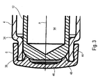
FIG. 3 eine weitere vereinfachte detaillierte Schnittansicht der Kolben-Zylinder-Einheit mit aufgesetzter Verschlusskappe.
-
FIG. 1 5 is a simplified perspective sectional view of a piston-cylinder unit according to the invention according to an embodiment as part of a personal safety system according to the invention, -
FIG. 2 a simplified detailed sectional view of this piston-cylinder unit in the region of its cap before attaching the cap and -
FIG. 3 another simplified detailed sectional view of the piston-cylinder unit with attached cap.
An einem hinteren Stirnende des Zylinders 4 bzw. der Kolben-Zylinder-Einheit 2 ist eine Steckeraufnahme 8 vorgesehen, welche als Stifte ausgeführte Kontakte 10 eines Zünders 18 aufweist.At a rear end of the
Im Innenraum des Zylinders 4 befindet sich ein beispielhaft als Hohlkolben ausgeführter Kolben 12. Der Kolben 12 ist einseitig geschlossen und umfasst in seinem Inneren eine Expansionskammer 14 zur Aufnahme von Druckgas. Der zum Ausfahren des Kolbens 12 notwendige Druck wird bei der dargestellten Kolben-Zylinder-Einheit 2 pyrotechnisch erzeugt.In the interior of the
Der pyrotechnische Antrieb umfasst eine Brennkammer 16, die in die Expansionskammer 14 des Kolbens 12 hineinragt. In der Brennkammer 16 befindet sich pyrotechnisches Material oder auch eine Druckgaspatrone. Das pyrotechnische Material kann mit Hilfe des Zünders 18 aktiviert werden.The pyrotechnic drive comprises a
Stirnseitig an der Brennkammer 16 vorhandene Sollbruchstellen 20 erlauben eine Expansion des freiwerdenden oder erzeugten Druckgases in die Expansionskammer 14 hinein, sodass der Kolben 12 in einer Axialrichtung A aus dem Zylinder 4 heraus bewegt werden kann. Bei dieser Bewegung wird die Verschlusskappe 6 von dem Kolben 12, welcher durch die Austrittsöffnung des Zylinders 4 hindurch bewegbar ist, durchbrochen bzw. komplett entfernt, insbesondere als Ganzes.On the front side of the
Die Expansionskammer 14 ist gegenüber einem Ringraum 21 zwischen der Innenseite des Zylinders 4 und der Außenseite des davon beabstandeten Kolbens 12 durch eine Dichtung abgedichtet, welche einen als ringförmiges Bauteil ausgebildeten Dichtungsträger 22 und einen in einer radial umlaufenden Nut dieses Dichtungsträgers 22 eingelegten O-Ring 24 umfasst. Die am zünderseitigen Ende des Kolbens 12 liegende Dichtung bewegt sich, wenn die Kolben-Zylinder-Einheit 2 aktiviert wird, gemeinsam mit dem Kolben 12 in Axialrichtung A und dichtet den brennkammerseitigen Hochdruckabschnitt im Zylinder 4 gegenüber dem Ringraum 21 ab. In der Endstellung des Kolbens 12 schlägt der Dichtungsträger 22 an den zylinderseitigen Anschlag 34 an, wobei ein im zünderseitigen Ende des Kolbens 12 vorhandener Verformungsbereich plastisch oder elastisch verformt werden kann, und die Bewegung des Zylinders 4 abzubremsen.The
Der Anschlag 34 wird durch einen umlaufenden Absatz des Zylinders 4 an seinem vorderen Ende gebildet.The
Bei einem fahrzeugintegrierbaren Personensicherheitssystem, z.B. einem Fußgängerschutzsystem wird durch das Ausfahren des Kolbens 12 beispielsweise eine Motorhaube 40 eines Fahrzeugs um eine definierte Strecke angehoben, sodass beim Aufschlag einer Person eine entsprechende Knautschzone durch Verformung der Motorhaube 40 zur Verfügung steht und ein Kontakt der Person mit dem darunterliegenden Motorblock verhindert bzw. abgemildert werden kann.In an on-board personal safety system, e.g. A pedestrian protection system is raised by the extension of the
Der Kolben 12 befindet sich in seiner Ausgangsstellung, in der sein vorderes Ende 36 etwas hinter der Austrittöffnung 32 zurückversetzt positioniert ist. An einem vorderen Ende der Zylinders 4 ist auf seiner äußeren Mantelfläche ein Rastvorsprung 38 vorhanden, welcher bevorzugt radial umlaufend ausgeführt ist. Allgemeiner gesagt befindet sich der Rastvorsprung 38 im Bereich der Austrittsöffnung 32.The
Bei montiertem Zustand der Verschlusskappe 6 (siehe
Die Verschlusskappe 6 umfasst eine Stirnwand 46, welche sich quer, bevorzugt im Wesentlichen senkrecht zu der Axialrichtung A erstreckt, und an die sich ein radial umlaufender Kragen 44 anschließt.The
Im montierten Zustand der Verschlusskappe 6 (siehe
Der Hinterschnitt 42 ist in einer Innenseite des Kragens 44 vorgesehen und befindet sich bevorzugt in einem Bereich des Kragens 44, der an die Stirnwand 46 angrenzt.The undercut 42 is provided in an inner side of the
Eine der Austrittsöffnung 32 abgewandte Außenseite der Stirnwand 46 ist bevorzugt konvex, weiterhin bevorzugt sphärisch geformt. Auf diese Weise soll verhindert werden, dass ein Benutzer die Kolben-Zylinder-Einheit 2 in einer möglichen ungünstigen Position, beispielsweise die Verschlusskappe nach unten, in Richtung eines festen Untergrundes weisend, auf der Stirnwand 46 stehend abstellt.One of the outlet opening 32 facing away from the outside of the
Der an dem Zylinder 4 vorhandene Rastvorsprung 38 und der Absatz an der Verschlusskappe 6, der den Hinterschnitt 42 begrenzt, liegen im montierten Zustand der Verschlusskappe 6 formschlüssig aneinander an. Dieser Zustand ist in
Eine der Austrittsöffnung 32 (betrachtet in montiertem Zustand der Verschlusskappe 6) zugewandte Innenseite der Verschlusskappe 6 ist mit einem Vorsprung 48 versehen. Dieser Vorsprung 48 ist bevorzugt aus einem plastisch und/oder elastisch verformbaren Material und tritt in montiertem Zustand der Verschlusskappe 6 mit dem vorderen Endbereich 36 des Kolbens 12 unter Vorspannung in Kontakt.One of the outlet opening 32 (viewed in the assembled state of the closure cap 6) facing inside of the
Über den umlaufenden Vorsprung 48 kann ausgehend von der Verschlusskappe 6 entgegen der Axialrichtung A wie auch in Radialrichtung eine Vorspannkraft in den Kolben 12 eingeleitet werden. Die Anlagefläche des Vorsprungs 48 ist eine Schrägfläche, hier eine abgerundete Kante des Kolbenendes. Mit anderen Worten wird der Kolben 12 von dem Vorsprung 48 in seiner vorgesehenen Ausgangsstellung gehalten. Ein möglicherweise zwischen der Außenseite des Kolbens 12 und der Innenseite des Zylinders 4 vorhandenes radiales Spiel kann akzeptiert werden, da der Kolben 12 über die Wulst 48 von der Verschlusskappe 6 gehalten wird. Dabei ist es vorteilhaft, dass die Verschlusskappe 6 über ihren Hinterschnitt 42 am Rastvorsprung 38 des Zylinders 4 formschlüssig gehalten ist und daher eine hohe Abzugskraft aufweist.Via the
Gemäß einem weiteren nicht gezeigten Ausführungsbeispiel kann die Verschlusskappe 6 mit einem Rastvorsprung versehen werden, der in eine passende Nut, welche in der äußeren Mantelfläche des Zylinders 4 vorhanden ist, greift. Ein solcher Rastvorsprung wird bevorzugt einem Bereich des Endes des Kragens 44 angeordnet, welches dem Deckel 46 abgewandt ist.According to a further embodiment, not shown, the
Die Kappe 6 ist insbesondere aus Kunststoff.The
Der Absatz am vorderen Ende des Zylinders bildet an seiner radialen Innenfläche eine Führungsfläche für das vordere Ende des Kolbens 12, der in der Ausgangsstellung im Bereich des Absatzes liegt.The shoulder at the front end of the cylinder forms at its radially inner surface a guide surface for the front end of the
Claims (14)
Applications Claiming Priority (1)
| Application Number | Priority Date | Filing Date | Title |
|---|---|---|---|
| DE201110116590 DE102011116590A1 (en) | 2011-10-21 | 2011-10-21 | Piston-cylinder unit, method of operation and method for producing such a piston-cylinder unit and in-vehicle personal safety system |
Publications (2)
| Publication Number | Publication Date |
|---|---|
| EP2583870A1 true EP2583870A1 (en) | 2013-04-24 |
| EP2583870B1 EP2583870B1 (en) | 2015-08-12 |
Family
ID=46419865
Family Applications (1)
| Application Number | Title | Priority Date | Filing Date |
|---|---|---|---|
| EP12004728.7A Active EP2583870B1 (en) | 2011-10-21 | 2012-06-25 | Piston-cylinder unit and personal safety system with such a piston-cylinder unit integrated into the vehicle |
Country Status (2)
| Country | Link |
|---|---|
| EP (1) | EP2583870B1 (en) |
| DE (1) | DE102011116590A1 (en) |
Cited By (3)
| Publication number | Priority date | Publication date | Assignee | Title |
|---|---|---|---|---|
| CN104742852A (en) * | 2013-12-26 | 2015-07-01 | 丰田合成株式会社 | Actuator |
| AT525257A4 (en) * | 2021-08-27 | 2023-02-15 | Astotec Automotive Gmbh | Pyrotechnic actuator |
| EP4303450A1 (en) * | 2022-07-05 | 2024-01-10 | Astotec Automotive GmbH | Pyrotechnic actuator |
Families Citing this family (2)
| Publication number | Priority date | Publication date | Assignee | Title |
|---|---|---|---|---|
| JP6308185B2 (en) * | 2015-08-26 | 2018-04-11 | トヨタ自動車株式会社 | Pop-up hood device actuator for vehicle and pop-up hood device for vehicle |
| DE102016219474B4 (en) | 2016-09-09 | 2019-07-04 | Joyson Safety Systems Germany Gmbh | Actuator and method for producing an actuator |
Citations (4)
| Publication number | Priority date | Publication date | Assignee | Title |
|---|---|---|---|---|
| US20020074787A1 (en) * | 1997-06-17 | 2002-06-20 | Lothar Anacker | Gas generator |
| WO2008026423A1 (en) * | 2006-08-31 | 2008-03-06 | Takata Corporation | Actuator, hood lifter, hood lifting system, and method of absorbing impact on actuator |
| US20090266638A1 (en) * | 2008-04-28 | 2009-10-29 | Toyoda Gosei Co., Ltd. | Actuator |
| EP2187065A1 (en) * | 2007-09-04 | 2010-05-19 | Daikin Industries, Ltd. | Gas pressure type actuator |
Family Cites Families (6)
| Publication number | Priority date | Publication date | Assignee | Title |
|---|---|---|---|---|
| FR1566533A (en) * | 1968-03-14 | 1969-05-09 | ||
| DE3238710C2 (en) * | 1982-10-19 | 1986-10-23 | TRW Repa GmbH, 7077 Alfdorf | Drive device with a piston driven pyrotechnically in a cylinder |
| DE4032384A1 (en) * | 1990-10-12 | 1992-04-16 | Audi Ag | BELT TIGHTER FOR MOTOR VEHICLES WITH A THREE-POINT BELT |
| US6942261B2 (en) * | 2003-08-14 | 2005-09-13 | Autoliv Asp, Inc. | Linear actuator with an internal dampening mechanism |
| DE102008025399B4 (en) * | 2008-05-28 | 2012-11-08 | Trw Airbag Systems Gmbh | Pyrotechnic drive unit |
| FR2931910B1 (en) * | 2008-05-30 | 2013-02-22 | Snpe Materiaux Energetiques | CURRENT CYLINDER, IN PARTICULAR FOR A SAFETY SYSTEM COMPRISING A MOTOR VEHICLE. |
-
2011
- 2011-10-21 DE DE201110116590 patent/DE102011116590A1/en active Pending
-
2012
- 2012-06-25 EP EP12004728.7A patent/EP2583870B1/en active Active
Patent Citations (4)
| Publication number | Priority date | Publication date | Assignee | Title |
|---|---|---|---|---|
| US20020074787A1 (en) * | 1997-06-17 | 2002-06-20 | Lothar Anacker | Gas generator |
| WO2008026423A1 (en) * | 2006-08-31 | 2008-03-06 | Takata Corporation | Actuator, hood lifter, hood lifting system, and method of absorbing impact on actuator |
| EP2187065A1 (en) * | 2007-09-04 | 2010-05-19 | Daikin Industries, Ltd. | Gas pressure type actuator |
| US20090266638A1 (en) * | 2008-04-28 | 2009-10-29 | Toyoda Gosei Co., Ltd. | Actuator |
Cited By (7)
| Publication number | Priority date | Publication date | Assignee | Title |
|---|---|---|---|---|
| CN104742852A (en) * | 2013-12-26 | 2015-07-01 | 丰田合成株式会社 | Actuator |
| EP2891583A1 (en) * | 2013-12-26 | 2015-07-08 | Toyoda Gosei Co., Ltd. | Actuator |
| US9340467B2 (en) | 2013-12-26 | 2016-05-17 | Toyoda Gosei Co., Ltd. | Actuator |
| AT525257A4 (en) * | 2021-08-27 | 2023-02-15 | Astotec Automotive Gmbh | Pyrotechnic actuator |
| AT525257B1 (en) * | 2021-08-27 | 2023-02-15 | Astotec Automotive Gmbh | Pyrotechnic actuator |
| EP4141264A1 (en) | 2021-08-27 | 2023-03-01 | Astotec Automotive GmbH | Pyrotechnic actuator and method of manufacturing its piston rod |
| EP4303450A1 (en) * | 2022-07-05 | 2024-01-10 | Astotec Automotive GmbH | Pyrotechnic actuator |
Also Published As
| Publication number | Publication date |
|---|---|
| EP2583870B1 (en) | 2015-08-12 |
| DE102011116590A1 (en) | 2013-04-25 |
Similar Documents
| Publication | Publication Date | Title |
|---|---|---|
| EP2583870B1 (en) | Piston-cylinder unit and personal safety system with such a piston-cylinder unit integrated into the vehicle | |
| DE102006011927A1 (en) | Pyrotechnic actuator, has cylindrical housing with gas discharge port in peripheral surface, where discharge port is blocked by piston prior to activation and opened by motion of piston after activation | |
| EP3478969B1 (en) | Master cylinder, in particular for a hydraulic clutch actuation device in motor vehicles | |
| EP0889812B1 (en) | Seat belt tensioner | |
| DE102011009300B4 (en) | Stopper with damper | |
| EP1637426B1 (en) | Buffer assembly | |
| DE102008039168B4 (en) | Pyrotechnic propulsion unit | |
| DE102007014403A1 (en) | Pyrotechnic drive unit and method for producing such a drive unit | |
| DE102013204745A1 (en) | Reciprocating shaft seal for hydraulic vibration damper used for motor vehicle, has gasket that is provided with main seal lip that is placed on piston rod, while farther lip touches piston rod | |
| DE102005057831B4 (en) | headlights | |
| DE102011087103A1 (en) | Master cylinder | |
| DE102011106514A1 (en) | Pyrotechnic actuator for belt tensioner used in occupant protection system of vehicle, has pressure chamber that is positioned between generator and piston and pressurized by combustion of fuel so as to move piston in axial direction | |
| DE102011082408A1 (en) | Master cylinder for hydraulic line for operating clutch of vehicle, has primary seal with rear part extending in form of flange in radial direction and over projections arranged over its circumference toward pressure spring | |
| DE102016219474B4 (en) | Actuator and method for producing an actuator | |
| EP1937520B1 (en) | Tensioning device for seatbelts with an olive-shaped piston | |
| DE102007034401A1 (en) | pretensioners | |
| WO2009027009A1 (en) | Reciprocating piston machine | |
| DE102016208091B4 (en) | Assembly for a motor vehicle | |
| DE202005016777U1 (en) | Fastening arrangement and motor vehicle | |
| DE102011118856A1 (en) | Vehicle safety system, particularly engine hood stand for passenger car, has piston with one component, which is fastened to actuator in longitudinal direction, where another component is fixed to engaging element | |
| DE102004055757B4 (en) | Airbag unit | |
| EP0755836B1 (en) | Mastercylinder | |
| DE10346279B4 (en) | Brake booster with hydraulic foot force assistance | |
| DE10325321B4 (en) | Brake cylinder arrangement for a hydraulic motor vehicle brake system and hydraulic motor vehicle brake system | |
| DE102014205268A1 (en) | Device for the adaptive degradation of crash energy |
Legal Events
| Date | Code | Title | Description |
|---|---|---|---|
| PUAI | Public reference made under article 153(3) epc to a published international application that has entered the european phase |
Free format text: ORIGINAL CODE: 0009012 |
|
| AK | Designated contracting states |
Kind code of ref document: A1 Designated state(s): AL AT BE BG CH CY CZ DE DK EE ES FI FR GB GR HR HU IE IS IT LI LT LU LV MC MK MT NL NO PL PT RO RS SE SI SK SM TR |
|
| AX | Request for extension of the european patent |
Extension state: BA ME |
|
| 17P | Request for examination filed |
Effective date: 20131024 |
|
| RBV | Designated contracting states (corrected) |
Designated state(s): AL AT BE BG CH CY CZ DE DK EE ES FI FR GB GR HR HU IE IS IT LI LT LU LV MC MK MT NL NO PL PT RO RS SE SI SK SM TR |
|
| REG | Reference to a national code |
Ref country code: DE Ref legal event code: R079 Ref document number: 502012004059 Country of ref document: DE Free format text: PREVIOUS MAIN CLASS: B60R0022195000 Ipc: B60R0021380000 |
|
| RIC1 | Information provided on ipc code assigned before grant |
Ipc: F15B 15/14 20060101ALI20141212BHEP Ipc: B60R 21/38 20110101AFI20141212BHEP Ipc: F15B 15/19 20060101ALI20141212BHEP Ipc: B60R 22/195 20060101ALI20141212BHEP |
|
| GRAP | Despatch of communication of intention to grant a patent |
Free format text: ORIGINAL CODE: EPIDOSNIGR1 |
|
| INTG | Intention to grant announced |
Effective date: 20150211 |
|
| GRAS | Grant fee paid |
Free format text: ORIGINAL CODE: EPIDOSNIGR3 |
|
| GRAA | (expected) grant |
Free format text: ORIGINAL CODE: 0009210 |
|
| AK | Designated contracting states |
Kind code of ref document: B1 Designated state(s): AL AT BE BG CH CY CZ DE DK EE ES FI FR GB GR HR HU IE IS IT LI LT LU LV MC MK MT NL NO PL PT RO RS SE SI SK SM TR |
|
| REG | Reference to a national code |
Ref country code: GB Ref legal event code: FG4D Free format text: NOT ENGLISH |
|
| REG | Reference to a national code |
Ref country code: CH Ref legal event code: EP |
|
| REG | Reference to a national code |
Ref country code: AT Ref legal event code: REF Ref document number: 741850 Country of ref document: AT Kind code of ref document: T Effective date: 20150815 |
|
| REG | Reference to a national code |
Ref country code: IE Ref legal event code: FG4D Free format text: LANGUAGE OF EP DOCUMENT: GERMAN |
|
| REG | Reference to a national code |
Ref country code: DE Ref legal event code: R096 Ref document number: 502012004059 Country of ref document: DE |
|
| REG | Reference to a national code |
Ref country code: LT Ref legal event code: MG4D |
|
| REG | Reference to a national code |
Ref country code: NL Ref legal event code: MP Effective date: 20150812 |
|
| PG25 | Lapsed in a contracting state [announced via postgrant information from national office to epo] |
Ref country code: NO Free format text: LAPSE BECAUSE OF FAILURE TO SUBMIT A TRANSLATION OF THE DESCRIPTION OR TO PAY THE FEE WITHIN THE PRESCRIBED TIME-LIMIT Effective date: 20151112 Ref country code: LV Free format text: LAPSE BECAUSE OF FAILURE TO SUBMIT A TRANSLATION OF THE DESCRIPTION OR TO PAY THE FEE WITHIN THE PRESCRIBED TIME-LIMIT Effective date: 20150812 Ref country code: LT Free format text: LAPSE BECAUSE OF FAILURE TO SUBMIT A TRANSLATION OF THE DESCRIPTION OR TO PAY THE FEE WITHIN THE PRESCRIBED TIME-LIMIT Effective date: 20150812 Ref country code: GR Free format text: LAPSE BECAUSE OF FAILURE TO SUBMIT A TRANSLATION OF THE DESCRIPTION OR TO PAY THE FEE WITHIN THE PRESCRIBED TIME-LIMIT Effective date: 20151113 Ref country code: FI Free format text: LAPSE BECAUSE OF FAILURE TO SUBMIT A TRANSLATION OF THE DESCRIPTION OR TO PAY THE FEE WITHIN THE PRESCRIBED TIME-LIMIT Effective date: 20150812 |
|
| PG25 | Lapsed in a contracting state [announced via postgrant information from national office to epo] |
Ref country code: PT Free format text: LAPSE BECAUSE OF FAILURE TO SUBMIT A TRANSLATION OF THE DESCRIPTION OR TO PAY THE FEE WITHIN THE PRESCRIBED TIME-LIMIT Effective date: 20151214 Ref country code: HR Free format text: LAPSE BECAUSE OF FAILURE TO SUBMIT A TRANSLATION OF THE DESCRIPTION OR TO PAY THE FEE WITHIN THE PRESCRIBED TIME-LIMIT Effective date: 20150812 Ref country code: RS Free format text: LAPSE BECAUSE OF FAILURE TO SUBMIT A TRANSLATION OF THE DESCRIPTION OR TO PAY THE FEE WITHIN THE PRESCRIBED TIME-LIMIT Effective date: 20150812 Ref country code: SE Free format text: LAPSE BECAUSE OF FAILURE TO SUBMIT A TRANSLATION OF THE DESCRIPTION OR TO PAY THE FEE WITHIN THE PRESCRIBED TIME-LIMIT Effective date: 20150812 Ref country code: ES Free format text: LAPSE BECAUSE OF FAILURE TO SUBMIT A TRANSLATION OF THE DESCRIPTION OR TO PAY THE FEE WITHIN THE PRESCRIBED TIME-LIMIT Effective date: 20150812 Ref country code: IS Free format text: LAPSE BECAUSE OF FAILURE TO SUBMIT A TRANSLATION OF THE DESCRIPTION OR TO PAY THE FEE WITHIN THE PRESCRIBED TIME-LIMIT Effective date: 20151212 Ref country code: PL Free format text: LAPSE BECAUSE OF FAILURE TO SUBMIT A TRANSLATION OF THE DESCRIPTION OR TO PAY THE FEE WITHIN THE PRESCRIBED TIME-LIMIT Effective date: 20150812 |
|
| PG25 | Lapsed in a contracting state [announced via postgrant information from national office to epo] |
Ref country code: NL Free format text: LAPSE BECAUSE OF FAILURE TO SUBMIT A TRANSLATION OF THE DESCRIPTION OR TO PAY THE FEE WITHIN THE PRESCRIBED TIME-LIMIT Effective date: 20150812 |
|
| PG25 | Lapsed in a contracting state [announced via postgrant information from national office to epo] |
Ref country code: DK Free format text: LAPSE BECAUSE OF FAILURE TO SUBMIT A TRANSLATION OF THE DESCRIPTION OR TO PAY THE FEE WITHIN THE PRESCRIBED TIME-LIMIT Effective date: 20150812 Ref country code: IT Free format text: LAPSE BECAUSE OF FAILURE TO SUBMIT A TRANSLATION OF THE DESCRIPTION OR TO PAY THE FEE WITHIN THE PRESCRIBED TIME-LIMIT Effective date: 20150812 Ref country code: EE Free format text: LAPSE BECAUSE OF FAILURE TO SUBMIT A TRANSLATION OF THE DESCRIPTION OR TO PAY THE FEE WITHIN THE PRESCRIBED TIME-LIMIT Effective date: 20150812 Ref country code: SK Free format text: LAPSE BECAUSE OF FAILURE TO SUBMIT A TRANSLATION OF THE DESCRIPTION OR TO PAY THE FEE WITHIN THE PRESCRIBED TIME-LIMIT Effective date: 20150812 Ref country code: CZ Free format text: LAPSE BECAUSE OF FAILURE TO SUBMIT A TRANSLATION OF THE DESCRIPTION OR TO PAY THE FEE WITHIN THE PRESCRIBED TIME-LIMIT Effective date: 20150812 |
|
| REG | Reference to a national code |
Ref country code: DE Ref legal event code: R097 Ref document number: 502012004059 Country of ref document: DE |
|
| PG25 | Lapsed in a contracting state [announced via postgrant information from national office to epo] |
Ref country code: RO Free format text: LAPSE BECAUSE OF FAILURE TO SUBMIT A TRANSLATION OF THE DESCRIPTION OR TO PAY THE FEE WITHIN THE PRESCRIBED TIME-LIMIT Effective date: 20150812 |
|
| PLBE | No opposition filed within time limit |
Free format text: ORIGINAL CODE: 0009261 |
|
| STAA | Information on the status of an ep patent application or granted ep patent |
Free format text: STATUS: NO OPPOSITION FILED WITHIN TIME LIMIT |
|
| REG | Reference to a national code |
Ref country code: FR Ref legal event code: PLFP Year of fee payment: 5 |
|
| 26N | No opposition filed |
Effective date: 20160513 |
|
| PG25 | Lapsed in a contracting state [announced via postgrant information from national office to epo] |
Ref country code: SI Free format text: LAPSE BECAUSE OF FAILURE TO SUBMIT A TRANSLATION OF THE DESCRIPTION OR TO PAY THE FEE WITHIN THE PRESCRIBED TIME-LIMIT Effective date: 20150812 |
|
| PG25 | Lapsed in a contracting state [announced via postgrant information from national office to epo] |
Ref country code: BE Free format text: LAPSE BECAUSE OF NON-PAYMENT OF DUE FEES Effective date: 20160630 |
|
| PG25 | Lapsed in a contracting state [announced via postgrant information from national office to epo] |
Ref country code: MC Free format text: LAPSE BECAUSE OF FAILURE TO SUBMIT A TRANSLATION OF THE DESCRIPTION OR TO PAY THE FEE WITHIN THE PRESCRIBED TIME-LIMIT Effective date: 20150812 |
|
| REG | Reference to a national code |
Ref country code: CH Ref legal event code: PL |
|
| GBPC | Gb: european patent ceased through non-payment of renewal fee |
Effective date: 20160625 |
|
| REG | Reference to a national code |
Ref country code: IE Ref legal event code: MM4A |
|
| PG25 | Lapsed in a contracting state [announced via postgrant information from national office to epo] |
Ref country code: LI Free format text: LAPSE BECAUSE OF NON-PAYMENT OF DUE FEES Effective date: 20160630 Ref country code: CH Free format text: LAPSE BECAUSE OF NON-PAYMENT OF DUE FEES Effective date: 20160630 |
|
| PG25 | Lapsed in a contracting state [announced via postgrant information from national office to epo] |
Ref country code: IE Free format text: LAPSE BECAUSE OF NON-PAYMENT OF DUE FEES Effective date: 20160625 Ref country code: GB Free format text: LAPSE BECAUSE OF NON-PAYMENT OF DUE FEES Effective date: 20160625 |
|
| REG | Reference to a national code |
Ref country code: FR Ref legal event code: PLFP Year of fee payment: 6 |
|
| PG25 | Lapsed in a contracting state [announced via postgrant information from national office to epo] |
Ref country code: SM Free format text: LAPSE BECAUSE OF FAILURE TO SUBMIT A TRANSLATION OF THE DESCRIPTION OR TO PAY THE FEE WITHIN THE PRESCRIBED TIME-LIMIT Effective date: 20150812 Ref country code: CY Free format text: LAPSE BECAUSE OF FAILURE TO SUBMIT A TRANSLATION OF THE DESCRIPTION OR TO PAY THE FEE WITHIN THE PRESCRIBED TIME-LIMIT Effective date: 20150812 Ref country code: HU Free format text: LAPSE BECAUSE OF FAILURE TO SUBMIT A TRANSLATION OF THE DESCRIPTION OR TO PAY THE FEE WITHIN THE PRESCRIBED TIME-LIMIT; INVALID AB INITIO Effective date: 20120625 |
|
| REG | Reference to a national code |
Ref country code: FR Ref legal event code: PLFP Year of fee payment: 7 |
|
| PG25 | Lapsed in a contracting state [announced via postgrant information from national office to epo] |
Ref country code: LU Free format text: LAPSE BECAUSE OF NON-PAYMENT OF DUE FEES Effective date: 20160625 Ref country code: MK Free format text: LAPSE BECAUSE OF FAILURE TO SUBMIT A TRANSLATION OF THE DESCRIPTION OR TO PAY THE FEE WITHIN THE PRESCRIBED TIME-LIMIT Effective date: 20150812 Ref country code: TR Free format text: LAPSE BECAUSE OF FAILURE TO SUBMIT A TRANSLATION OF THE DESCRIPTION OR TO PAY THE FEE WITHIN THE PRESCRIBED TIME-LIMIT Effective date: 20150812 Ref country code: MT Free format text: LAPSE BECAUSE OF FAILURE TO SUBMIT A TRANSLATION OF THE DESCRIPTION OR TO PAY THE FEE WITHIN THE PRESCRIBED TIME-LIMIT Effective date: 20150812 |
|
| PG25 | Lapsed in a contracting state [announced via postgrant information from national office to epo] |
Ref country code: BG Free format text: LAPSE BECAUSE OF FAILURE TO SUBMIT A TRANSLATION OF THE DESCRIPTION OR TO PAY THE FEE WITHIN THE PRESCRIBED TIME-LIMIT Effective date: 20150812 |
|
| REG | Reference to a national code |
Ref country code: AT Ref legal event code: MM01 Ref document number: 741850 Country of ref document: AT Kind code of ref document: T Effective date: 20170625 |
|
| PG25 | Lapsed in a contracting state [announced via postgrant information from national office to epo] |
Ref country code: AL Free format text: LAPSE BECAUSE OF FAILURE TO SUBMIT A TRANSLATION OF THE DESCRIPTION OR TO PAY THE FEE WITHIN THE PRESCRIBED TIME-LIMIT Effective date: 20150812 |
|
| PG25 | Lapsed in a contracting state [announced via postgrant information from national office to epo] |
Ref country code: AT Free format text: LAPSE BECAUSE OF NON-PAYMENT OF DUE FEES Effective date: 20170625 |
|
| REG | Reference to a national code |
Ref country code: DE Ref legal event code: R082 Ref document number: 502012004059 Country of ref document: DE Representative=s name: MEHNERT, BERNHARD, DE Ref country code: DE Ref legal event code: R081 Ref document number: 502012004059 Country of ref document: DE Owner name: ZF AIRBAG GERMANY GMBH, DE Free format text: FORMER OWNER: TRW AIRBAG SYSTEMS GMBH, 84544 ASCHAU, DE |
|
| PGFP | Annual fee paid to national office [announced via postgrant information from national office to epo] |
Ref country code: FR Payment date: 20230510 Year of fee payment: 12 Ref country code: DE Payment date: 20230630 Year of fee payment: 12 |
|
| P01 | Opt-out of the competence of the unified patent court (upc) registered |
Effective date: 20230628 |