EP2583750A1 - Kitchen worktop with rotary actuation means and cooking receptacle that can be used with said worktop - Google Patents
Kitchen worktop with rotary actuation means and cooking receptacle that can be used with said worktop Download PDFInfo
- Publication number
- EP2583750A1 EP2583750A1 EP12778192.0A EP12778192A EP2583750A1 EP 2583750 A1 EP2583750 A1 EP 2583750A1 EP 12778192 A EP12778192 A EP 12778192A EP 2583750 A1 EP2583750 A1 EP 2583750A1
- Authority
- EP
- European Patent Office
- Prior art keywords
- cooking
- vessel
- cooking vessel
- support plate
- coupling member
- Prior art date
- Legal status (The legal status is an assumption and is not a legal conclusion. Google has not performed a legal analysis and makes no representation as to the accuracy of the status listed.)
- Granted
Links
Images
Classifications
-
- B—PERFORMING OPERATIONS; TRANSPORTING
- B01—PHYSICAL OR CHEMICAL PROCESSES OR APPARATUS IN GENERAL
- B01F—MIXING, e.g. DISSOLVING, EMULSIFYING OR DISPERSING
- B01F33/00—Other mixers; Mixing plants; Combinations of mixers
- B01F33/50—Movable or transportable mixing devices or plants
- B01F33/501—Movable mixing devices, i.e. readily shifted or displaced from one place to another, e.g. portable during use
- B01F33/5014—Movable mixing devices, i.e. readily shifted or displaced from one place to another, e.g. portable during use movable by human force, e.g. kitchen or table devices
-
- A—HUMAN NECESSITIES
- A47—FURNITURE; DOMESTIC ARTICLES OR APPLIANCES; COFFEE MILLS; SPICE MILLS; SUCTION CLEANERS IN GENERAL
- A47J—KITCHEN EQUIPMENT; COFFEE MILLS; SPICE MILLS; APPARATUS FOR MAKING BEVERAGES
- A47J43/00—Implements for preparing or holding food, not provided for in other groups of this subclass
- A47J43/04—Machines for domestic use not covered elsewhere, e.g. for grinding, mixing, stirring, kneading, emulsifying, whipping or beating foodstuffs, e.g. power-driven
- A47J43/07—Parts or details, e.g. mixing tools, whipping tools
- A47J43/075—Safety devices
- A47J43/0761—Safety devices for machines with tools driven from the lower side
- A47J43/0772—Safety devices for machines with tools driven from the lower side activated by the proper positioning of the cover
- A47J43/0777—Safety devices for machines with tools driven from the lower side activated by the proper positioning of the cover in which the activating element on the cover transmits a signal to a safety device in the base element via the mixing bowl removably seated on this base element, e.g. pin on the cover moves a pushrod in the bowl handle to operate safety switch in the base element
-
- A—HUMAN NECESSITIES
- A47—FURNITURE; DOMESTIC ARTICLES OR APPLIANCES; COFFEE MILLS; SPICE MILLS; SUCTION CLEANERS IN GENERAL
- A47J—KITCHEN EQUIPMENT; COFFEE MILLS; SPICE MILLS; APPARATUS FOR MAKING BEVERAGES
- A47J27/00—Cooking-vessels
- A47J27/004—Cooking-vessels with integral electrical heating means
-
- A—HUMAN NECESSITIES
- A47—FURNITURE; DOMESTIC ARTICLES OR APPLIANCES; COFFEE MILLS; SPICE MILLS; SUCTION CLEANERS IN GENERAL
- A47J—KITCHEN EQUIPMENT; COFFEE MILLS; SPICE MILLS; APPARATUS FOR MAKING BEVERAGES
- A47J43/00—Implements for preparing or holding food, not provided for in other groups of this subclass
- A47J43/04—Machines for domestic use not covered elsewhere, e.g. for grinding, mixing, stirring, kneading, emulsifying, whipping or beating foodstuffs, e.g. power-driven
- A47J43/046—Machines for domestic use not covered elsewhere, e.g. for grinding, mixing, stirring, kneading, emulsifying, whipping or beating foodstuffs, e.g. power-driven with tools driven from the bottom side
- A47J43/0465—Machines for domestic use not covered elsewhere, e.g. for grinding, mixing, stirring, kneading, emulsifying, whipping or beating foodstuffs, e.g. power-driven with tools driven from the bottom side with magnetic drive
-
- A—HUMAN NECESSITIES
- A47—FURNITURE; DOMESTIC ARTICLES OR APPLIANCES; COFFEE MILLS; SPICE MILLS; SUCTION CLEANERS IN GENERAL
- A47J—KITCHEN EQUIPMENT; COFFEE MILLS; SPICE MILLS; APPARATUS FOR MAKING BEVERAGES
- A47J43/00—Implements for preparing or holding food, not provided for in other groups of this subclass
- A47J43/04—Machines for domestic use not covered elsewhere, e.g. for grinding, mixing, stirring, kneading, emulsifying, whipping or beating foodstuffs, e.g. power-driven
- A47J43/07—Parts or details, e.g. mixing tools, whipping tools
- A47J43/08—Driving mechanisms
- A47J43/085—Driving mechanisms for machines with tools driven from the lower side
-
- B—PERFORMING OPERATIONS; TRANSPORTING
- B01—PHYSICAL OR CHEMICAL PROCESSES OR APPARATUS IN GENERAL
- B01F—MIXING, e.g. DISSOLVING, EMULSIFYING OR DISPERSING
- B01F31/00—Mixers with shaking, oscillating, or vibrating mechanisms
- B01F31/44—Mixers with shaking, oscillating, or vibrating mechanisms with stirrers performing an oscillatory, vibratory or shaking movement
-
- B—PERFORMING OPERATIONS; TRANSPORTING
- B01—PHYSICAL OR CHEMICAL PROCESSES OR APPARATUS IN GENERAL
- B01F—MIXING, e.g. DISSOLVING, EMULSIFYING OR DISPERSING
- B01F33/00—Other mixers; Mixing plants; Combinations of mixers
- B01F33/45—Magnetic mixers; Mixers with magnetically driven stirrers
- B01F33/453—Magnetic mixers; Mixers with magnetically driven stirrers using supported or suspended stirring elements
- B01F33/4535—Magnetic mixers; Mixers with magnetically driven stirrers using supported or suspended stirring elements using a stud for supporting the stirring element
-
- B—PERFORMING OPERATIONS; TRANSPORTING
- B01—PHYSICAL OR CHEMICAL PROCESSES OR APPARATUS IN GENERAL
- B01F—MIXING, e.g. DISSOLVING, EMULSIFYING OR DISPERSING
- B01F35/00—Accessories for mixers; Auxiliary operations or auxiliary devices; Parts or details of general application
- B01F35/20—Measuring; Control or regulation
- B01F35/21—Measuring
- B01F35/211—Measuring of the operational parameters
- B01F35/2115—Temperature
-
- B—PERFORMING OPERATIONS; TRANSPORTING
- B01—PHYSICAL OR CHEMICAL PROCESSES OR APPARATUS IN GENERAL
- B01F—MIXING, e.g. DISSOLVING, EMULSIFYING OR DISPERSING
- B01F35/00—Accessories for mixers; Auxiliary operations or auxiliary devices; Parts or details of general application
- B01F35/45—Closures or doors specially adapted for mixing receptacles; Operating mechanisms therefor
-
- B—PERFORMING OPERATIONS; TRANSPORTING
- B01—PHYSICAL OR CHEMICAL PROCESSES OR APPARATUS IN GENERAL
- B01F—MIXING, e.g. DISSOLVING, EMULSIFYING OR DISPERSING
- B01F35/00—Accessories for mixers; Auxiliary operations or auxiliary devices; Parts or details of general application
- B01F35/60—Safety arrangements
- B01F35/605—Safety devices concerning the operation of the mixer
-
- B—PERFORMING OPERATIONS; TRANSPORTING
- B01—PHYSICAL OR CHEMICAL PROCESSES OR APPARATUS IN GENERAL
- B01F—MIXING, e.g. DISSOLVING, EMULSIFYING OR DISPERSING
- B01F35/00—Accessories for mixers; Auxiliary operations or auxiliary devices; Parts or details of general application
- B01F35/90—Heating or cooling systems
- B01F35/94—Heating or cooling systems using radiation, e.g. microwaves or electromagnetic radiation
-
- H—ELECTRICITY
- H05—ELECTRIC TECHNIQUES NOT OTHERWISE PROVIDED FOR
- H05B—ELECTRIC HEATING; ELECTRIC LIGHT SOURCES NOT OTHERWISE PROVIDED FOR; CIRCUIT ARRANGEMENTS FOR ELECTRIC LIGHT SOURCES, IN GENERAL
- H05B6/00—Heating by electric, magnetic or electromagnetic fields
- H05B6/02—Induction heating
- H05B6/10—Induction heating apparatus, other than furnaces, for specific applications
- H05B6/12—Cooking devices
- H05B6/1209—Cooking devices induction cooking plates or the like and devices to be used in combination with them
-
- H—ELECTRICITY
- H05—ELECTRIC TECHNIQUES NOT OTHERWISE PROVIDED FOR
- H05B—ELECTRIC HEATING; ELECTRIC LIGHT SOURCES NOT OTHERWISE PROVIDED FOR; CIRCUIT ARRANGEMENTS FOR ELECTRIC LIGHT SOURCES, IN GENERAL
- H05B6/00—Heating by electric, magnetic or electromagnetic fields
- H05B6/02—Induction heating
- H05B6/10—Induction heating apparatus, other than furnaces, for specific applications
- H05B6/12—Cooking devices
- H05B6/129—Cooking devices induction ovens
Definitions
- the present invention relates to a cooking hob provided with a continuous support plate, made for example of glass, glass ceramic or the like, and rotary driving means located below the support plate for driving rotary blades or paddles installed in a cooking vessel located on a treatment area of the support plate.
- the present invention also relates to a cooking vessel usable with said cooking hob.
- Patent US-A-5549382 describes a cooking hob provided with a support plate having with several cooking areas, in each of which a cooking vessel can be supported.
- the hob includes heating means associated with each cooking area and driving means aligned with one of the cooking areas.
- the driving means comprise a motor which rotates a lower magnetic coupling member located below the support plate in a position close enough to it to magnetically transmit torque to an upper magnetic coupling member attached to a stirrer located inside a cooking vessel placed on the corresponding cooking area.
- Document DE-A-1131372 discloses a cooking hob comprising magnetic coupling between a lower magnetic coupling member rotatably driven by a motorised driving device and an upper magnetic coupling member connected to rotary blades or paddles installed inside a vessel.
- the magnetic coupling is established through a support plate on which the vessel rests.
- Patent application DE-A-102006052475 discloses a cooking hob provided with a glass, glass ceramic or the like support plate with several cooking areas associated with heating means, where one of the cooking areas includes a lower magnetic coupling member rotatably driven by a motor to establish magnetic coupling through the support plate with an upper magnetic coupling member attached to a stirrer located inside a vessel placed on one of the cooking areas to rotate the stirrer inside the vessel.
- a drawback of these cooking hobs equipped with a substantially smooth support plate and driving means to rotate a lower magnetic element and thereby establish magnetic coupling through the support plate is that if for any reason the rotary blades or paddles increase resistance to rotation or are locked inside the vessel, for example due to the conditions of the food being processed, then the entire vessel tends to rotate on the support plate being pushed by the driving means with the risk of ruining the culinary preparation inside the vessel, scratching the support plate or even causing an accident.
- An advantage of the cooking hobs provided with a continuous glass, glass ceramic or the like support plate is that the support plate has a very easy to clean smooth and completely cleared upper surface. Nevertheless, this smooth and cleared surface offers very little resistance to the rotation of the vessel. Accordingly, there is a need to provide means preventing the rotation of the vessel on the plate and means preventing the operation of the driving means if the vessel is not placed on the treatment area of the support plate in a predetermined angular position.
- the present invention contributes to mitigating the aforementioned and other drawbacks providing a cooking hob with rotary driving means, comprising a support plate which has a treatment area capable of supporting a cooking vessel provided with rotary blades or paddles connected to an upper magnetic coupling member, a lower magnetic coupling member rotatably assembled below the support plate, and a drive actuator operatively connected for rotating said lower magnetic coupling member and magnetically transmitting torque to said upper magnetic coupling member of said cooking vessel.
- the cooking hob of the present invention comprises a lower magnetic element installed below the support plate at a predetermined distance from a rotating shaft of the lower magnetic coupling member.
- This lower magnetic element creates a magnetic attractive force on an upper magnetic element located in the cooking vessel at the same predetermined distance from a rotating shaft of the upper magnetic coupling member when the cooking vessel is located in a predetermined angular position on the treatment area.
- the magnetic attractive force between the lower and upper magnetic elements combined with the distance from them to the respective rotating shafts of the lower and upper magnetic coupling members creates a resistant torque which prevents the cooking vessel from rotating on the treatment area of the support plate due to a driving torque produced by the rotation of the lower coupling member when for any reason the rotary blades encounter resistance to rotation or are locked inside the cooking vessel, for example due to the conditions of the food which is being processed, provided that the driving torque does not exceed the resistant torque.
- the lower magnetic coupling member is assembled in a moving support, and a position change actuator is operatively connected to move said moving support between an operative position, in which the lower magnetic coupling member is close enough to the support plate to magnetically transmit said torque to the upper magnetic coupling member when the cooking vessel is located on the treatment area, and an inoperative position, in which the lower magnetic coupling member is far enough from the support plate so as to not transmit the torque.
- the lower magnetic element is installed in the moving support such that when the moving support is in said operative position the lower magnetic element is close enough to the support plate to create said magnetic attractive force on the upper magnetic element of the cooking vessel, and when the moving support is in said inoperative position, the lower magnetic element is far enough from the support plate so as to not create the magnetic attractive force.
- the cooking hob further comprises a wireless energy emitting element installed in the moving support to emit a wireless energy supply that can be received by a wireless energy receiving element located in the cooking vessel for the purpose of supplying at least one electronic safety control circuit installed in the cooking vessel.
- the mentioned wireless energy emitting element comprises a lower coil supplied by a power supply.
- This lower coil is arranged in the moving support below the support plate in a position such that it is coaxial to a corresponding upper coil installed in the cooking vessel when the cooking vessel is located in said predetermined angular position on the treatment area.
- the lower and upper coils are aligned and close enough to one another so that the lower coil, which is supplied by the power supply, establishes an electromagnetic coupling through the support plate with said upper coil of the cooking vessel, said upper coil acting as the mentioned wireless energy receiving element.
- the lower and upper coils are far enough from one another so as to not establish the electromagnetic coupling.
- the cooking hob includes a wireless signal receiver arranged in a position below the support plate suitable for receiving a control signal emitted by a wireless signal emitter located in the cooking vessel when the cooking vessel is located in said predetermined angular position on the treatment area.
- This wireless signal emitter of the cooking vessel is in connection with the mentioned electronic safety control circuit, and said wireless signal receiver of the hob is in connection with an electronic control device configured for allowing, preventing or modifying the operation of the mentioned drive actuator, which drives the rotation of the lower magnetic coupling member, as a consequence of receiving or not receiving said control signal.
- the cooking hob further comprises heating means arranged below the support plate for heating the cooking vessel when it is located on the treatment area, in which case the mentioned electronic control device is further configured for allowing, preventing or modifying the operation of said heating means as a consequence of receiving or not receiving the control signal.
- the heating means comprise an induction heating device in the form of a planar ring arranged adjacent to a lower surface of the support plate in the treatment area. This induction heating device has a central opening in which the lower magnetic coupling member is housed when the moving support is in the operative position to allow the lower magnetic coupling member to rotate as close as possible to the lower surface of the support plate.
- the lower magnetic element is a permanent magnet or a body made of a ferromagnetic material and the wireless signal receiver is an infrared receiver.
- the present invention provides a cooking vessel usable with a cooking hob provided with rotary driving means, such as a cooking hob according to the first aspect of the present invention for example.
- the mentioned cooking vessel comprises a vessel body configured for being placed on a treatment area of a support plate of said cooking hob, rotary blades or paddles installed inside said vessel body, and an upper magnetic coupling member connected to said rotary blades or paddles.
- the mentioned upper magnetic coupling member is rotated by a lower magnetic coupling member installed in the cooking hob below said support plate in said treatment area and rotatably driven by a drive actuator when the cooking vessel is placed on the treatment area.
- the cooking vessel of the present invention is characterised in that it comprises an upper magnetic element fixed to the vessel body at a predetermined distance from a rotating shaft of said upper magnetic coupling member.
- This upper magnetic element is arranged for creating a magnetic attractive force on a lower magnetic element installed in the cooking hob below the support plate and at the same predetermined distance from a rotating shaft of the lower magnetic coupling member when the cooking vessel is located in a predetermined angular position on the treatment area.
- the magnetic attractive force between the lower and upper magnetic elements combined with the distance from them to the respective rotating shafts of the lower and upper magnetic coupling members contributes to preventing the cooking vessel from rotating on the treatment area of the support plate.
- the cooking vessel comprises a wireless energy receiving element fixed to the vessel body in a suitable position for receiving a wireless energy supply emitted by a wireless energy emitting element installed in the cooking hob below the support plate.
- This wireless receiving element of the cooking vessel is capable of converting said wireless energy supply into electric power for supplying an electronic safety control circuit installed in the cooking vessel.
- the wireless energy receiving element comprises an upper coil arranged in a position such that said upper coil is coaxial and adjacent to a corresponding lower coil supplied by a power supply and arranged in the cooking hob below the support plate when the cooking vessel is located in said predetermined angular position on the treatment area. Therefore, the lower coil of the cooking hob, which is supplied by the power supply and acts as said wireless energy emitting element, establishes an electromagnetic coupling through the support plate with said upper coil of the cooking vessel, and it produces an electric current which is used for supplying the electronic safety control circuit.
- the upper magnetic element and the upper coil are preferably located in an appendage fixed to said vessel body. More preferably, said appendage is adjacent to a bottom of the vessel body, such that the upper magnetic element and the upper coil are very close to an upper surface of the support plate of the hob when the bottom of the cooking vessel rests on it. In one embodiment, the mentioned appendage is connected to a handle fixed to the vessel body.
- the cooking vessel usually comprises a lid configured for at least partially covering an upper opening of the vessel body.
- the mentioned lid is coupled to the vessel body in a correctly closed position and said electronic safety control circuit comprises a position sensor arranged for detecting a detectable element installed in said lid when the lid is in said correctly closed position.
- the cooking vessel further comprises a wireless signal emitter which emits a control signal representative of said correctly closed position of the lid, or of an incorrectly closed position of the lid, that can be received by a wireless signal receiver located in the hob below the support plate.
- the wireless signal receiver of the hob is in connection with an electronic control device configured for allowing, preventing or modifying the operation of the mentioned drive actuator which drives the rotation of the lower magnetic coupling member as a consequence of receiving or not receiving said control signal.
- the wireless signal emitter is fixed to the vessel body in a suitable position so that said control signal is received by said wireless signal receiver of the hob when the cooking vessel is located in said predetermined angular position on the treatment area.
- the wireless signal emitter can be located in the same appendage fixed to said vessel body supporting the upper magnetic element and the upper coil.
- the detectable element is a permanent magnet and said position sensor can be any device capable of detecting a magnetic field, such as a Reed relay or a Hall effect sensor.
- the wireless signal emitter can be an infrared emitter for example.
- the upper magnetic element is a permanent magnet or a body made of a ferromagnetic material.
- the bottom of the vessel body is preferably configured for being heated by a heating device of the hob, and more preferably by an induction heating device of the hob when the vessel is located on the treatment area of the support plate of the hob.
- the cooking vessel can include a temperature sensor for detecting the temperature of the vessel body and an identifier of the vessel type.
- the control signal emitted by the wireless signal emitter includes information relating to the temperature detected by the temperature sensor and information relating to the vessel type, such that the electronic control device can adapt the operation of the hob according to the data received by the wireless signal receiver.
- reference number 1 generally designates a cooking hob with rotary driving means according to an embodiment of a first aspect of the present invention and reference number 50 generally designates a cooking vessel provided with rotary blades or paddles according to an embodiment of a second aspect of the present invention.
- the cooking hob 1 comprises a continuous support plate 2, made of glass, glass ceramic or the like, which has several cooking areas 13 and a treatment area 3 all of them indicated graphically.
- the cooking areas 13 are conventionally associated with respective heating means (not shown) located below the support plate 2.
- the treatment area 3 is configured for supporting the mentioned cooking vessel 50 which, as best shown in Figures 3 , 4 and 5 , comprises a vessel body 51 which has a bottom 52 configured for being heated by electromagnetic induction and an upper opening.
- Rotary blades or paddles 53 connected by means of a blade shaft 64 to an upper magnetic coupling member 54 housed in a concavity 65 formed in the bottom 52 are installed inside the vessel body 51.
- the upper magnetic coupling member 54 is very close to the support plate 2 without contacting it.
- the rotary blades or paddles 53, the blade shaft 64 and the upper magnetic coupling member 54 can rotate integrally about an upper rotating shaft E2.
- the support plate 2 of the cooking hob 1 is supported on a frame 20 and a fixed support 21 is fixed to said frame 20 by means of struts 22 maintaining said fixed support 21 located below the treatment area 3 of the support plate 2 and spaced from a lower surface of the support plate 2.
- the fixed support 21 supports three vertical screws 23 (only one of which is shown in Figures 3 , 4 and 5 ) connected to respective position change pulleys 24 linked to one another by a position change belt 25.
- One of said screws 23 ( Figures 2 , 4 and 5 ) is further connected to a gear wheel 26 meshing with a cogwheel or worm screw 27 driven by a position change actuator 7, such as an electric motor.
- a lower magnetic coupling member 4 is rotatably assembled in said moving support 5 below the support plate 2.
- the mentioned lower magnetic coupling member 4 is connected by means of a drive shaft 16 to a driven pulley 17.
- the lower magnetic coupling member 4, said drive shaft 16 and said driven pulley 17 can rotate integrally about a lower rotating shaft E1, which is centred in relation to the treatment area 3 of the support plate 2.
- the driven pulley 17 is connected by a drive belt 18 to a drive pulley 19 driven by a drive actuator 6, such as an electric motor, installed in said moving support 5. An activation of said drive actuator 6 thus rotates the lower magnetic coupling member 4.
- the lower magnetic coupling member 4 When the moving support 5 is in said operative position ( Figure 5 ), the lower magnetic coupling member 4 is very close to a lower surface of the support plate 2 without contacting it. Therefore, when the cooking vessel 50 is located on the treatment area 3 and the moving support 5 is in the operative position, the lower and upper rotating shafts E1, E2 are mutually aligned and the lower magnetic coupling member 4 is close enough to the support plate 2 to magnetically transmit torque to the upper magnetic coupling member 54 and to the rotary blades or paddles 53 of the cooking vessel 50. When the moving support 5 is in said inoperative position ( Figures 3 and 4 ), the lower magnetic coupling member 4 is far enough from the support plate 2 so as to not transmit the mentioned torque.
- the cooking hob 1 further comprises a lower magnetic element 8, which is installed in the moving support 5 below the support plate 2 at a predetermined distance from the mentioned lower rotating shaft E1 of the lower magnetic coupling member 4, and the cooking vessel 50 comprises an upper magnetic element 58 installed in an appendage 61 fixed to the vessel body 51 at the same predetermined distance from the mentioned upper rotating shaft E2 of the upper magnetic coupling member 54.
- the appendage 61 can be located adjacent to the bottom 52 of the vessel body 51 and the cooking vessel 50 can include a handle 63 with an upper end fixed to the vessel body 51 close to the upper opening and a lower end connected to the appendage 61.
- the lower magnetic element 8 is located on the moving support 5 in a constant predetermined angular position about the lower rotating shaft E1, such that when the cooking vessel 50 is located on the treatment area 3 of the support plate 2 with the mentioned appendage 61 orientated such that the upper magnetic element 58 is in the same predetermined angular position as the lower magnetic element 8 ( Figures 1 , 4 and 5 ), the upper magnetic element 58 and the lower magnetic element 8 are mutually aligned.
- the lower magnetic element 8 of the cooking hob 1 creates a magnetic attractive force on the upper magnetic element 58 of the cooking vessel 50, and this magnetic attractive force combined with the distance from the lower and upper magnetic elements 8, 58 to the lower and upper rotating shafts E1, E2, which are also mutually aligned in this position, creates a resistant torque opposing the driving torque produced by the rotation of the lower coupling member 4 combined with the resistance to rotation of the rotary blades 53 inside the cooking vessel 50.
- the mentioned driving torque tends to rotate the cooking vessel 50 on the treatment area 3 of the support plate 2 and increases when for any reason the rotary blades or paddles 53 encounter greater resistance to rotation or are locked inside the cooking vessel 50, for example due to the conditions of the food being processed. Accordingly, the resistant torque provided by the lower and upper magnetic elements 8, 58 prevents the cooking vessel 50 from rotating on the treatment area 3 of the support plate 2 provided that the driving torque does not exceed the resistant torque.
- the lower and upper magnetic elements 8, 58 can both be permanent magnets, or one of them can be a permanent magnet and the other a body made of a ferromagnetic material.
- the cooking hob 1 includes an electronic control device connected to the drive actuator 6 and configured for stopping the operation of the drive actuator 6 when the current consumed by it increases above a predetermined threshold.
- the cooking vessel 50 comprises a lid 55 configured for covering the mentioned upper opening of the vessel body 51 and an electronic safety control circuit configured for preventing or modifying the operation of the cooking hob 1 if the lid 55 is not coupled to the upper opening of the vessel body 51 in a correctly closed position.
- a detectable element 60 is installed in the lid, and the electronic safety control circuit comprises a position sensor 57 arranged for detecting said detectable element 60 when the lid 55 is in the correctly closed position and a wireless signal emitter 59 which emits a control signal representative of said correctly closed position of the lid 55.
- the cooking hob 1 comprises a wireless signal receiver 9 located below the support plate 2 and capable of receiving the control signal, and the mentioned electronic control device of the cooking hob 1 is further configured for allowing the operation of the drive actuator 6 only if the control signal is received.
- the detectable element 60 can be a permanent magnet and said position sensor 57 can be a Reed relay or a Hall effect sensor.
- the wireless signal emitter 59 can be an infrared emitter and the wireless signal receiver 9 can be an infrared receiver.
- the wireless signal emitter 59 can be installed in the appendage 61 of the cooking vessel 50 and the wireless signal receiver 9 can be installed in the moving support 5 such that wireless signal emitter 59 and the wireless signal receiver 9 are facing on opposite sides of the support plate 2 when the cooking vessel 50 is located on the treatment area 3 of the support plate 2 in the predetermined angular position, and very close to one another when the moving support 5 is furthermore in the operative position.
- the electronic safety control circuit of the cooking vessel 50 can alternatively be configured for making the wireless signal emitter 59 emit the control signal if the lid 55 is in an incorrectly closed position and the electronic control device of the cooking hob 1 can be configured for preventing the operation of the drive actuator 6 if the control signal is received.
- the cooking hob optionally includes heating means 10 arranged below the support plate 2 for heating the cooking vessel 50 when it is located on the treatment area 3.
- these heating means 10 comprise an induction heating device 11 in the form of a planar ring arranged adjacent to a lower surface of the support plate 2 in the treatment area 3.
- the induction heating device 11 has a central opening in which the lower magnetic coupling member 5 is housed when the moving support 5 is in the operative position.
- the bottom 52 of the vessel body 51 of the cooking vessel 50 is configured for being heated by the induction heating device 11 of the cooking hob 1 when the vessel 50 is located on the treatment area 3 of the support plate 2 of the cooking hob 1.
- the electronic control device of the cooking hob 1 is further configured for allowing, preventing or modifying the operation of said heating means 10 as a consequence of said received or not received control signal.
- the cooking vessel 50 includes a temperature sensor 66 ( Figures 4 and 5 ) for detecting the temperature of the vessel body 51 and an identifier of the vessel type, for example in the form of data stored in a memory of the electronic safety control circuit.
- the wireless signal emitter 59 is used to include information relating to the temperature detected by the temperature sensor 66 and information relating to the vessel type in the emitted control signal. Therefore, the operation of the cooking hob 1 is further adapted by the electronic control device to the vessel type and to the temperature of the vessel body 51 according to the control signal received by the wireless signal receiver 9 of the cooking hob 1.
- the cooking hob 1 further comprises a wireless energy emitting element installed in the moving support 5.
- This wireless energy emitting element is configured for emitting a wireless energy supply that can be received by a wireless energy receiving element fixed to the vessel body 51 for supplying the electronic safety control circuit installed in the cooking vessel 50.
- the wireless energy emitting element can have a lower coil 12 supplied by a power supply and said wireless energy receiving element can have a corresponding upper coil 56 installed in the appendage 61 of the cooking vessel 50 and in connection with the electronic safety control circuit.
- the lower coil 12 is arranged in a position on the moving support 5 and below the support plate 2 such that when the cooking vessel 50 is located in said predetermined angular position on the treatment area 3 the lower coil 12 is coaxial with the upper coil 56.
- the upper coil 56 is very close to the upper surface of the support plate 2
- the moving support 5 is in the operative position ( Figure 5 ) the lower coil 12 is very close to the lower surface of the support plate 2.
- the lower coil 12 powered up by the power supply establishes an electromagnetic coupling with the upper coil 56 of the cooking vessel 50, and this produces an electric supply current in the upper coil which is used for supplying the electronic safety control circuit of the cooking vessel 50.
- the cooking hob 1 of the present invention includes a control panel 30 connected with the electronic control device and with an electric supply system of the cooking hob 1.
- this control panel 30 comprises control buttons or keys 31 and a visual display 32 allowing a user to control the operation of the heating means associated with the cooking areas 13, the heating means 10 associated with the treatment area 3, and the drive actuator 6 which drives the rotation of the rotary blades or paddles inside the cooking vessel 50 when it is located on the treatment area 3 of the support plate 2.
Abstract
Description
- The present invention relates to a cooking hob provided with a continuous support plate, made for example of glass, glass ceramic or the like, and rotary driving means located below the support plate for driving rotary blades or paddles installed in a cooking vessel located on a treatment area of the support plate. The present invention also relates to a cooking vessel usable with said cooking hob.
- Patent
US-A-5549382 describes a cooking hob provided with a support plate having with several cooking areas, in each of which a cooking vessel can be supported. The hob includes heating means associated with each cooking area and driving means aligned with one of the cooking areas. The driving means comprise a motor which rotates a lower magnetic coupling member located below the support plate in a position close enough to it to magnetically transmit torque to an upper magnetic coupling member attached to a stirrer located inside a cooking vessel placed on the corresponding cooking area. - Document
DE-A-1131372 discloses a cooking hob comprising magnetic coupling between a lower magnetic coupling member rotatably driven by a motorised driving device and an upper magnetic coupling member connected to rotary blades or paddles installed inside a vessel. The magnetic coupling is established through a support plate on which the vessel rests. - Patent application
DE-A-102006052475 discloses a cooking hob provided with a glass, glass ceramic or the like support plate with several cooking areas associated with heating means, where one of the cooking areas includes a lower magnetic coupling member rotatably driven by a motor to establish magnetic coupling through the support plate with an upper magnetic coupling member attached to a stirrer located inside a vessel placed on one of the cooking areas to rotate the stirrer inside the vessel. - A drawback of these cooking hobs equipped with a substantially smooth support plate and driving means to rotate a lower magnetic element and thereby establish magnetic coupling through the support plate is that if for any reason the rotary blades or paddles increase resistance to rotation or are locked inside the vessel, for example due to the conditions of the food being processed, then the entire vessel tends to rotate on the support plate being pushed by the driving means with the risk of ruining the culinary preparation inside the vessel, scratching the support plate or even causing an accident.
- Documents
DE-A-3000593 ,DE-A-3836099 ,EP-A-0725556 ,WO-A-9631739 US-A-4587406 describe different wireless communication systems for communicating between a cooking vessel and a cooking hob provided with a cooking area with electric heating means on which the vessel is placed for the purpose of transmitting data relating to the cooking conditions, especially the temperature in the vessel, and controlling the electric heating means according to the data received from the vessel by means of a control device. - An advantage of the cooking hobs provided with a continuous glass, glass ceramic or the like support plate is that the support plate has a very easy to clean smooth and completely cleared upper surface. Nevertheless, this smooth and cleared surface offers very little resistance to the rotation of the vessel. Accordingly, there is a need to provide means preventing the rotation of the vessel on the plate and means preventing the operation of the driving means if the vessel is not placed on the treatment area of the support plate in a predetermined angular position.
- According to a first aspect, the present invention contributes to mitigating the aforementioned and other drawbacks providing a cooking hob with rotary driving means, comprising a support plate which has a treatment area capable of supporting a cooking vessel provided with rotary blades or paddles connected to an upper magnetic coupling member, a lower magnetic coupling member rotatably assembled below the support plate, and a drive actuator operatively connected for rotating said lower magnetic coupling member and magnetically transmitting torque to said upper magnetic coupling member of said cooking vessel.
- The cooking hob of the present invention comprises a lower magnetic element installed below the support plate at a predetermined distance from a rotating shaft of the lower magnetic coupling member. This lower magnetic element creates a magnetic attractive force on an upper magnetic element located in the cooking vessel at the same predetermined distance from a rotating shaft of the upper magnetic coupling member when the cooking vessel is located in a predetermined angular position on the treatment area.
- The magnetic attractive force between the lower and upper magnetic elements combined with the distance from them to the respective rotating shafts of the lower and upper magnetic coupling members creates a resistant torque which prevents the cooking vessel from rotating on the treatment area of the support plate due to a driving torque produced by the rotation of the lower coupling member when for any reason the rotary blades encounter resistance to rotation or are locked inside the cooking vessel, for example due to the conditions of the food which is being processed, provided that the driving torque does not exceed the resistant torque.
- In one embodiment, the lower magnetic coupling member is assembled in a moving support, and a position change actuator is operatively connected to move said moving support between an operative position, in which the lower magnetic coupling member is close enough to the support plate to magnetically transmit said torque to the upper magnetic coupling member when the cooking vessel is located on the treatment area, and an inoperative position, in which the lower magnetic coupling member is far enough from the support plate so as to not transmit the torque.
- In such case, the lower magnetic element is installed in the moving support such that when the moving support is in said operative position the lower magnetic element is close enough to the support plate to create said magnetic attractive force on the upper magnetic element of the cooking vessel, and when the moving support is in said inoperative position, the lower magnetic element is far enough from the support plate so as to not create the magnetic attractive force.
- In one embodiment, the cooking hob further comprises a wireless energy emitting element installed in the moving support to emit a wireless energy supply that can be received by a wireless energy receiving element located in the cooking vessel for the purpose of supplying at least one electronic safety control circuit installed in the cooking vessel.
- In one embodiment, the mentioned wireless energy emitting element comprises a lower coil supplied by a power supply. This lower coil is arranged in the moving support below the support plate in a position such that it is coaxial to a corresponding upper coil installed in the cooking vessel when the cooking vessel is located in said predetermined angular position on the treatment area.
- Therefore, when the moving support is in the operative position and the cooking vessel is located in the predetermined angular position on the treatment area, the lower and upper coils are aligned and close enough to one another so that the lower coil, which is supplied by the power supply, establishes an electromagnetic coupling through the support plate with said upper coil of the cooking vessel, said upper coil acting as the mentioned wireless energy receiving element. When the moving support is in the inoperative position, the lower and upper coils are far enough from one another so as to not establish the electromagnetic coupling.
- Furthermore, the cooking hob includes a wireless signal receiver arranged in a position below the support plate suitable for receiving a control signal emitted by a wireless signal emitter located in the cooking vessel when the cooking vessel is located in said predetermined angular position on the treatment area. This wireless signal emitter of the cooking vessel is in connection with the mentioned electronic safety control circuit, and said wireless signal receiver of the hob is in connection with an electronic control device configured for allowing, preventing or modifying the operation of the mentioned drive actuator, which drives the rotation of the lower magnetic coupling member, as a consequence of receiving or not receiving said control signal.
- In one embodiment, the cooking hob further comprises heating means arranged below the support plate for heating the cooking vessel when it is located on the treatment area, in which case the mentioned electronic control device is further configured for allowing, preventing or modifying the operation of said heating means as a consequence of receiving or not receiving the control signal. In one embodiment, the heating means comprise an induction heating device in the form of a planar ring arranged adjacent to a lower surface of the support plate in the treatment area. This induction heating device has a central opening in which the lower magnetic coupling member is housed when the moving support is in the operative position to allow the lower magnetic coupling member to rotate as close as possible to the lower surface of the support plate.
- In one embodiment, the lower magnetic element is a permanent magnet or a body made of a ferromagnetic material and the wireless signal receiver is an infrared receiver.
- According to a second aspect, the present invention provides a cooking vessel usable with a cooking hob provided with rotary driving means, such as a cooking hob according to the first aspect of the present invention for example.
- The mentioned cooking vessel comprises a vessel body configured for being placed on a treatment area of a support plate of said cooking hob, rotary blades or paddles installed inside said vessel body, and an upper magnetic coupling member connected to said rotary blades or paddles. The mentioned upper magnetic coupling member is rotated by a lower magnetic coupling member installed in the cooking hob below said support plate in said treatment area and rotatably driven by a drive actuator when the cooking vessel is placed on the treatment area.
- The cooking vessel of the present invention is characterised in that it comprises an upper magnetic element fixed to the vessel body at a predetermined distance from a rotating shaft of said upper magnetic coupling member. This upper magnetic element is arranged for creating a magnetic attractive force on a lower magnetic element installed in the cooking hob below the support plate and at the same predetermined distance from a rotating shaft of the lower magnetic coupling member when the cooking vessel is located in a predetermined angular position on the treatment area.
- According to that described above, the magnetic attractive force between the lower and upper magnetic elements combined with the distance from them to the respective rotating shafts of the lower and upper magnetic coupling members contributes to preventing the cooking vessel from rotating on the treatment area of the support plate.
- In one embodiment, the cooking vessel comprises a wireless energy receiving element fixed to the vessel body in a suitable position for receiving a wireless energy supply emitted by a wireless energy emitting element installed in the cooking hob below the support plate. This wireless receiving element of the cooking vessel is capable of converting said wireless energy supply into electric power for supplying an electronic safety control circuit installed in the cooking vessel.
- In one embodiment, the wireless energy receiving element comprises an upper coil arranged in a position such that said upper coil is coaxial and adjacent to a corresponding lower coil supplied by a power supply and arranged in the cooking hob below the support plate when the cooking vessel is located in said predetermined angular position on the treatment area. Therefore, the lower coil of the cooking hob, which is supplied by the power supply and acts as said wireless energy emitting element, establishes an electromagnetic coupling through the support plate with said upper coil of the cooking vessel, and it produces an electric current which is used for supplying the electronic safety control circuit.
- The upper magnetic element and the upper coil are preferably located in an appendage fixed to said vessel body. More preferably, said appendage is adjacent to a bottom of the vessel body, such that the upper magnetic element and the upper coil are very close to an upper surface of the support plate of the hob when the bottom of the cooking vessel rests on it. In one embodiment, the mentioned appendage is connected to a handle fixed to the vessel body.
- The cooking vessel usually comprises a lid configured for at least partially covering an upper opening of the vessel body. The mentioned lid is coupled to the vessel body in a correctly closed position and said electronic safety control circuit comprises a position sensor arranged for detecting a detectable element installed in said lid when the lid is in said correctly closed position. The cooking vessel further comprises a wireless signal emitter which emits a control signal representative of said correctly closed position of the lid, or of an incorrectly closed position of the lid, that can be received by a wireless signal receiver located in the hob below the support plate. The wireless signal receiver of the hob is in connection with an electronic control device configured for allowing, preventing or modifying the operation of the mentioned drive actuator which drives the rotation of the lower magnetic coupling member as a consequence of receiving or not receiving said control signal.
- In one embodiment, the wireless signal emitter is fixed to the vessel body in a suitable position so that said control signal is received by said wireless signal receiver of the hob when the cooking vessel is located in said predetermined angular position on the treatment area. For example, the wireless signal emitter can be located in the same appendage fixed to said vessel body supporting the upper magnetic element and the upper coil. In one embodiment, the detectable element is a permanent magnet and said position sensor can be any device capable of detecting a magnetic field, such as a Reed relay or a Hall effect sensor. The wireless signal emitter can be an infrared emitter for example. The upper magnetic element is a permanent magnet or a body made of a ferromagnetic material.
- The bottom of the vessel body is preferably configured for being heated by a heating device of the hob, and more preferably by an induction heating device of the hob when the vessel is located on the treatment area of the support plate of the hob.
- The cooking vessel can include a temperature sensor for detecting the temperature of the vessel body and an identifier of the vessel type. In such case, the control signal emitted by the wireless signal emitter includes information relating to the temperature detected by the temperature sensor and information relating to the vessel type, such that the electronic control device can adapt the operation of the hob according to the data received by the wireless signal receiver.
- The foregoing and other advantages and features will be better understood from the following detailed description of one embodiment with reference to the attached drawings, in which:
-
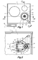
Figure 1 is a top plan view of a cooking hob with rotary driving means according to an embodiment of a first aspect of the present invention and of a cooking vessel according to an embodiment of a second aspect of the present invention arranged on a treatment area of the cooking hob; -
Figure 2 is a partial bottom plan view of the treatment area of the cooking hob ofFigure 1 ; -
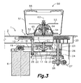
Figure 3 is a partial cross-section view taken along plane III-III ofFigure 1 ; -
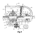
Figure 4 is a partial cross-section view taken along plane IV-IV ofFigure 1 with a moving support in an inactive position; and -
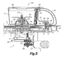
Figure 5 is a partial cross-section view similar toFigure 4 , but with the moving support in an active position. - Referring first to
Figure 1 ,reference number 1 generally designates a cooking hob with rotary driving means according to an embodiment of a first aspect of the present invention andreference number 50 generally designates a cooking vessel provided with rotary blades or paddles according to an embodiment of a second aspect of the present invention. Thecooking hob 1 comprises acontinuous support plate 2, made of glass, glass ceramic or the like, which hasseveral cooking areas 13 and atreatment area 3 all of them indicated graphically. Thecooking areas 13 are conventionally associated with respective heating means (not shown) located below thesupport plate 2. - The
treatment area 3 is configured for supporting the mentionedcooking vessel 50 which, as best shown inFigures 3 ,4 and5 , comprises avessel body 51 which has a bottom 52 configured for being heated by electromagnetic induction and an upper opening. Rotary blades or paddles 53 connected by means of ablade shaft 64 to an uppermagnetic coupling member 54 housed in aconcavity 65 formed in the bottom 52 are installed inside thevessel body 51. When thevessel body 51 rests on thesupport plate 2 the uppermagnetic coupling member 54 is very close to thesupport plate 2 without contacting it. The rotary blades or paddles 53, theblade shaft 64 and the uppermagnetic coupling member 54 can rotate integrally about an upper rotating shaft E2. - As shown in
Figures 2 to 5 , thesupport plate 2 of thecooking hob 1 is supported on aframe 20 and a fixedsupport 21 is fixed to saidframe 20 by means ofstruts 22 maintaining said fixedsupport 21 located below thetreatment area 3 of thesupport plate 2 and spaced from a lower surface of thesupport plate 2. The fixedsupport 21 supports three vertical screws 23 (only one of which is shown inFigures 3 ,4 and5 ) connected to respective position change pulleys 24 linked to one another by aposition change belt 25. One of said screws 23 (Figures 2 ,4 and5 ) is further connected to agear wheel 26 meshing with a cogwheel orworm screw 27 driven by aposition change actuator 7, such as an electric motor. - There is located between the
support plate 2 and the fixed support 21 a movingsupport 5, which has fixed thereto three nuts 28 (only one of which is shown inFigure 4 ) respectively coupled to the threescrews 23. Therefore, activation of the mentionedposition change actuator 7 moves the movingsupport 5 between an upper active position (Figure 5 ) and a lower inactive position (Figures 3 and4 ). - A lower
magnetic coupling member 4 is rotatably assembled in said movingsupport 5 below thesupport plate 2. The mentioned lowermagnetic coupling member 4 is connected by means of adrive shaft 16 to a drivenpulley 17. The lowermagnetic coupling member 4, saiddrive shaft 16 and said drivenpulley 17 can rotate integrally about a lower rotating shaft E1, which is centred in relation to thetreatment area 3 of thesupport plate 2. The drivenpulley 17 is connected by adrive belt 18 to a drivepulley 19 driven by adrive actuator 6, such as an electric motor, installed in said movingsupport 5. An activation of saiddrive actuator 6 thus rotates the lowermagnetic coupling member 4. - When the moving
support 5 is in said operative position (Figure 5 ), the lowermagnetic coupling member 4 is very close to a lower surface of thesupport plate 2 without contacting it. Therefore, when thecooking vessel 50 is located on thetreatment area 3 and the movingsupport 5 is in the operative position, the lower and upper rotating shafts E1, E2 are mutually aligned and the lowermagnetic coupling member 4 is close enough to thesupport plate 2 to magnetically transmit torque to the uppermagnetic coupling member 54 and to the rotary blades or paddles 53 of thecooking vessel 50. When the movingsupport 5 is in said inoperative position (Figures 3 and4 ), the lowermagnetic coupling member 4 is far enough from thesupport plate 2 so as to not transmit the mentioned torque. - As shown in
Figures 4 and5 , thecooking hob 1 further comprises a lowermagnetic element 8, which is installed in the movingsupport 5 below thesupport plate 2 at a predetermined distance from the mentioned lower rotating shaft E1 of the lowermagnetic coupling member 4, and thecooking vessel 50 comprises an uppermagnetic element 58 installed in anappendage 61 fixed to thevessel body 51 at the same predetermined distance from the mentioned upper rotating shaft E2 of the uppermagnetic coupling member 54. For example, theappendage 61 can be located adjacent to the bottom 52 of thevessel body 51 and thecooking vessel 50 can include ahandle 63 with an upper end fixed to thevessel body 51 close to the upper opening and a lower end connected to theappendage 61. When the movingsupport 5 is in the operative position, the lowermagnetic element 8 is very close to the lower surface of thesupport plate 2 and when thecooking vessel 50 rests on thesupport plate 2, the uppermagnetic element 58 is very close to the upper surface of thesupport plate 2. - The lower
magnetic element 8 is located on the movingsupport 5 in a constant predetermined angular position about the lower rotating shaft E1, such that when thecooking vessel 50 is located on thetreatment area 3 of thesupport plate 2 with the mentionedappendage 61 orientated such that the uppermagnetic element 58 is in the same predetermined angular position as the lower magnetic element 8 (Figures 1 ,4 and5 ), the uppermagnetic element 58 and the lowermagnetic element 8 are mutually aligned. - Therefore, when the
cooking vessel 50 is located on thetreatment area 3 of thesupport plate 2 in the predetermined angular position and the moving support is in the operative position (Figure 5 ), the lowermagnetic element 8 of thecooking hob 1 creates a magnetic attractive force on the uppermagnetic element 58 of thecooking vessel 50, and this magnetic attractive force combined with the distance from the lower and uppermagnetic elements lower coupling member 4 combined with the resistance to rotation of therotary blades 53 inside thecooking vessel 50. - The mentioned driving torque tends to rotate the
cooking vessel 50 on thetreatment area 3 of thesupport plate 2 and increases when for any reason the rotary blades or paddles 53 encounter greater resistance to rotation or are locked inside thecooking vessel 50, for example due to the conditions of the food being processed. Accordingly, the resistant torque provided by the lower and uppermagnetic elements cooking vessel 50 from rotating on thetreatment area 3 of thesupport plate 2 provided that the driving torque does not exceed the resistant torque. The lower and uppermagnetic elements - In the event that the
rotary blades 53 encounter unusually large resistance to rotation or are locked inside thecooking vessel 50, the current consumed by thedrive actuator 6 would accordingly increase. Thecooking hob 1 includes an electronic control device connected to thedrive actuator 6 and configured for stopping the operation of thedrive actuator 6 when the current consumed by it increases above a predetermined threshold. - As shown in
Figures 1 ,3 ,4 and5 , thecooking vessel 50 comprises alid 55 configured for covering the mentioned upper opening of thevessel body 51 and an electronic safety control circuit configured for preventing or modifying the operation of thecooking hob 1 if thelid 55 is not coupled to the upper opening of thevessel body 51 in a correctly closed position. Adetectable element 60 is installed in the lid, and the electronic safety control circuit comprises aposition sensor 57 arranged for detecting saiddetectable element 60 when thelid 55 is in the correctly closed position and awireless signal emitter 59 which emits a control signal representative of said correctly closed position of thelid 55. Thecooking hob 1 comprises awireless signal receiver 9 located below thesupport plate 2 and capable of receiving the control signal, and the mentioned electronic control device of thecooking hob 1 is further configured for allowing the operation of thedrive actuator 6 only if the control signal is received. - For example, the
detectable element 60 can be a permanent magnet and saidposition sensor 57 can be a Reed relay or a Hall effect sensor. For example, thewireless signal emitter 59 can be an infrared emitter and thewireless signal receiver 9 can be an infrared receiver. Optionally, thewireless signal emitter 59 can be installed in theappendage 61 of thecooking vessel 50 and thewireless signal receiver 9 can be installed in the movingsupport 5 such thatwireless signal emitter 59 and thewireless signal receiver 9 are facing on opposite sides of thesupport plate 2 when thecooking vessel 50 is located on thetreatment area 3 of thesupport plate 2 in the predetermined angular position, and very close to one another when the movingsupport 5 is furthermore in the operative position. - It will be understood that the electronic safety control circuit of the
cooking vessel 50 can alternatively be configured for making thewireless signal emitter 59 emit the control signal if thelid 55 is in an incorrectly closed position and the electronic control device of thecooking hob 1 can be configured for preventing the operation of thedrive actuator 6 if the control signal is received. - The cooking hob optionally includes heating means 10 arranged below the
support plate 2 for heating thecooking vessel 50 when it is located on thetreatment area 3. For example, these heating means 10 comprise aninduction heating device 11 in the form of a planar ring arranged adjacent to a lower surface of thesupport plate 2 in thetreatment area 3. Theinduction heating device 11 has a central opening in which the lowermagnetic coupling member 5 is housed when the movingsupport 5 is in the operative position. Accordingly, the bottom 52 of thevessel body 51 of thecooking vessel 50 is configured for being heated by theinduction heating device 11 of thecooking hob 1 when thevessel 50 is located on thetreatment area 3 of thesupport plate 2 of thecooking hob 1. In such case, the electronic control device of thecooking hob 1 is further configured for allowing, preventing or modifying the operation of said heating means 10 as a consequence of said received or not received control signal. - For example, the
cooking vessel 50 includes a temperature sensor 66 (Figures 4 and5 ) for detecting the temperature of thevessel body 51 and an identifier of the vessel type, for example in the form of data stored in a memory of the electronic safety control circuit. Thewireless signal emitter 59 is used to include information relating to the temperature detected by thetemperature sensor 66 and information relating to the vessel type in the emitted control signal. Therefore, the operation of thecooking hob 1 is further adapted by the electronic control device to the vessel type and to the temperature of thevessel body 51 according to the control signal received by thewireless signal receiver 9 of thecooking hob 1. - The
cooking hob 1 further comprises a wireless energy emitting element installed in the movingsupport 5. This wireless energy emitting element is configured for emitting a wireless energy supply that can be received by a wireless energy receiving element fixed to thevessel body 51 for supplying the electronic safety control circuit installed in thecooking vessel 50. For example, the wireless energy emitting element can have alower coil 12 supplied by a power supply and said wireless energy receiving element can have a correspondingupper coil 56 installed in theappendage 61 of thecooking vessel 50 and in connection with the electronic safety control circuit. - The
lower coil 12 is arranged in a position on the movingsupport 5 and below thesupport plate 2 such that when thecooking vessel 50 is located in said predetermined angular position on thetreatment area 3 thelower coil 12 is coaxial with theupper coil 56. When thecooking vessel 50 is located in said predetermined angular position on thetreatment area 3 theupper coil 56 is very close to the upper surface of thesupport plate 2, and when the movingsupport 5 is in the operative position (Figure 5 ) thelower coil 12 is very close to the lower surface of thesupport plate 2. In this position, thelower coil 12 powered up by the power supply establishes an electromagnetic coupling with theupper coil 56 of thecooking vessel 50, and this produces an electric supply current in the upper coil which is used for supplying the electronic safety control circuit of thecooking vessel 50. - Going back to
Figure 1 , thecooking hob 1 of the present invention includes acontrol panel 30 connected with the electronic control device and with an electric supply system of thecooking hob 1. For example, thiscontrol panel 30 comprises control buttons orkeys 31 and avisual display 32 allowing a user to control the operation of the heating means associated with thecooking areas 13, the heating means 10 associated with thetreatment area 3, and thedrive actuator 6 which drives the rotation of the rotary blades or paddles inside thecooking vessel 50 when it is located on thetreatment area 3 of thesupport plate 2. - A person skilled in the art will be able to introduce modifications and variations in the embodiment shown and described without departing from the scope of the present invention as it is defined in the attached claims.
Claims (21)
- A cooking hob (1) with rotary driving means, of the type comprising:a support plate (2) which has a treatment area (3) capable of supporting a cooking vessel (50) provided with rotary blades or paddles (53) connected to an upper magnetic coupling member (54);a lower magnetic coupling member (4) rotatably assembled below the support plate (2); anda drive actuator (6) operatively connected for rotating said lower magnetic coupling member (4) and magnetically transmitting torque to said upper magnetic coupling member (54) of said cooking vessel (50),characterised in that at least one lower magnetic element (8) is installed below the support plate (2) at a predetermined distance from a lower rotating shaft (E1) of the lower magnetic coupling member (4) to create a magnetic attractive force on an upper magnetic element (58) installed in the cooking vessel (50) at said predetermined distance from an upper rotating shaft (E2) of the upper magnetic coupling member (54) when the cooking vessel (50) is located in a predetermined angular position on the treatment area (3).
- The cooking hob according to claim 1, characterised in that said lower magnetic coupling member (4) is assembled on a moving support (5), and a position change actuator (7) is operatively connected to move said moving support (5) between an operative position, in which the lower magnetic coupling member (4) is close enough to the support plate (2) to magnetically transmit said torque to the upper magnetic coupling member (54) when the cooking vessel (50) is located on the treatment area (3), and an inoperative position, in which the lower magnetic coupling member (4) is far enough from the support plate (2) so as to not transmit the torque, and in that the lower magnetic element (8) is installed on the moving support (5) to create said magnetic attractive force on the upper magnetic element (58) of the cooking vessel (50) when the moving support (5) is in said operative position.
- The cooking hob according to claim 2, characterised in that a wireless energy emitting element is installed in the moving support (5) to emit a wireless energy supply that can be received by a wireless energy receiving element installed in the cooking vessel (50) for supplying at least one electronic safety control circuit installed in the cooking vessel (50).
- The cooking hob according to claim 3, characterised in that said wireless energy emitting element comprises a lower coil (12) supplied by a power supply and arranged in a position below the support plate (2) in which said lower coil (12) is coaxial and adjacent to a corresponding upper coil (56) installed in the cooking vessel (50) when the moving support (5) is in said operative position and the cooking vessel (50) is located in said predetermined angular position on the treatment area (3) to establish a magnetic coupling with said upper coil (56) of the cooking vessel (50), said upper coil (56) acting as said wireless energy receiving element.
- The cooking hob according to claim 4, characterised in that a wireless signal receiver (9) is arranged in a position below the support plate (2) suitable for receiving a control signal emitted by a wireless signal emitter (59) installed in the cooking vessel (50) in connection with said electronic safety control circuit when the cooking vessel (50) is located in said predetermined angular position on the treatment area (3), said wireless signal receiver (9) being in connection with an electronic control device configured for allowing, preventing or modifying the operation of said drive actuator (6) as a consequence of said received or not received control signal.
- The cooking hob according to claim 5, characterised in that heating means (10) are arranged below the support plate (2) for heating the cooking vessel (50) when it is located on the treatment area (3), and said electronic control device is further configured for allowing, preventing or modifying the operation of said heating means (10) as a consequence of said received or not received control signal.
- The cooking hob according to claim 6, characterised in that said heating means (10) comprise an induction heating device (11) in the form of a planar ring arranged adjacent to a lower surface of the support plate (2) in the treatment area (3), said induction heating device (11) having a central opening in which the lower magnetic coupling member (5) is housed when the moving support (5) is in the operative position.
- The cooking hob according to claim 1, characterised in that said lower magnetic element (8) is a permanent magnet or a body made of a ferromagnetic material.
- The cooking hob according to claim 5, characterised in that said wireless signal receiver (9) is an infrared receiver.
- A cooking vessel (50) usable with a cooking hob (1) with rotary driving means, of the type comprising:a vessel body (51) configured for being placed on a treatment area (3) of a support plate (2) of said cooking hob (1);rotary blades or paddles (53) rotatably installed inside said vessel body (51) and connected to an upper magnetic coupling member (54), which is rotated by a lower magnetic coupling member (4) installed in the cooking hob (1) below said support plate (2) in said treatment area (3) and rotatably driven by a drive actuator (6);characterised in that an upper magnetic element (58) is fixed to the vessel body (51) at a predetermined distance from an upper rotating shaft (E2) of said upper magnetic coupling member (54) and arranged for creating a magnetic attractive force on a lower magnetic element (8) installed in the cooking hob (1) below the support plate (2) and at said predetermined distance from a lower rotating shaft (E1) of the lower magnetic coupling member (4) when the cooking vessel (50) is located in a predetermined angular position on the treatment area (3).
- The cooking vessel according to claim 10, characterised in that a wireless energy receiving element is fixed to the vessel body (51) in a position suitable for receiving a wireless energy supply emitted by a wireless energy emitting element installed in the cooking hob (1) below the support plate (2), said wireless receiving element being capable of converting said wireless energy supply into electric power for supplying an electronic safety control circuit installed in the cooking vessel (50).
- The cooking vessel according to claim 10, characterised in that said wireless energy receiving element comprises an upper coil (56) arranged in a position which is coaxial and adjacent to a corresponding lower coil (12) supplied by a power supply and arranged in the cooking hob (1) below the support plate (2) when the cooking vessel (50) is located in said predetermined angular position on the treatment area (3), to establish a magnetic coupling with said lower coil (12) of the cooking hob (1), said lower coil (12) acting as said wireless energy emitting element.
- The cooking vessel according to claim 12, characterised in that said upper magnetic element (58) and said upper coil (56) are located in an appendage (61) fixed to said vessel body (51).
- The cooking vessel according to claim 13, characterised in that said appendage (61) is adjacent to a bottom (52) of the vessel body (51) and is connected to a handle (63) fixed to said vessel body (51).
- The cooking vessel according to any one of claims 11 to 14, characterised in that the cooking vessel (50) comprises a lid (55) configured for at least partially covering an upper opening of the vessel body (51) in a correctly closed position, and said electronic safety control circuit comprises a position sensor (57) arranged for detecting a detectable element (60) installed in said lid (55) when the lid (55) is in said correctly closed position or in an incorrectly closed position and a wireless signal emitter (59) which emits a control signal representative of said correctly closed position or incorrectly closed position of the lid (55) that can be received by a wireless signal receiver (9) located in the cooking hob (1) below the support plate (2).
- The cooking vessel according to claim 15, characterised in that said wireless signal emitter (59) is fixed to the vessel body (51) in a position suitable for said control signal to be received by said wireless signal receiver (9) of the cooking hob (1) when the cooking vessel (50) is located in said predetermined angular position on the treatment area (3).
- The cooking vessel according to claim 16, characterised in that the wireless signal emitter (59) is located in said appendage (61) fixed to said vessel body (51).
- The cooking vessel according to claim 10, characterised in that said upper magnetic element (58) is a permanent magnet or a body made of a ferromagnetic material.
- The cooking vessel according to claim 15, characterised in that said detectable element (60) is a permanent magnet and said position sensor (57) is selected from a group comprising a Reed relay and a Hall effect sensor.
- The cooking vessel according to claim 15, characterised in that said wireless signal emitter (59) is an infrared emitter.
- The cooking vessel according to claim 10, characterised in that said vessel body (51) comprises a bottom (52) configured for being heated by an induction heating device (11) of the cooking hob (1) when the vessel (50) is located on the treatment area (3) of the support plate (2) of the cooking hob (1).
Applications Claiming Priority (2)
| Application Number | Priority Date | Filing Date | Title |
|---|---|---|---|
| ES201100642A ES2393378B1 (en) | 2011-06-07 | 2011-06-07 | KITCHEN BASKET WITH ROTATING DRIVING MEDIA AND KITCHEN CONTAINER USED WITH SIDE UP |
| PCT/ES2012/000132 WO2012168506A1 (en) | 2011-06-07 | 2012-05-10 | Kitchen worktop with rotary actuation means and cooking receptacle that can be used with said worktop |
Publications (3)
| Publication Number | Publication Date |
|---|---|
| EP2583750A1 true EP2583750A1 (en) | 2013-04-24 |
| EP2583750A4 EP2583750A4 (en) | 2015-12-02 |
| EP2583750B1 EP2583750B1 (en) | 2017-07-26 |
Family
ID=47290508
Family Applications (1)
| Application Number | Title | Priority Date | Filing Date |
|---|---|---|---|
| EP12778192.0A Not-in-force EP2583750B1 (en) | 2011-06-07 | 2012-05-10 | Kitchen worktop with rotary actuation means and cooking receptacle that can be used with said worktop |
Country Status (5)
| Country | Link |
|---|---|
| US (1) | US9237829B2 (en) |
| EP (1) | EP2583750B1 (en) |
| CN (1) | CN102933292B (en) |
| ES (2) | ES2393378B1 (en) |
| WO (1) | WO2012168506A1 (en) |
Cited By (9)
| Publication number | Priority date | Publication date | Assignee | Title |
|---|---|---|---|---|
| WO2016185305A1 (en) * | 2015-05-21 | 2016-11-24 | BSH Hausgeräte GmbH | Cooking utensil |
| WO2016185304A1 (en) * | 2015-05-21 | 2016-11-24 | BSH Hausgeräte GmbH | Hob device |
| WO2016185303A1 (en) * | 2015-05-21 | 2016-11-24 | BSH Hausgeräte GmbH | Cooking utensil |
| EP3685718A1 (en) * | 2019-01-24 | 2020-07-29 | Millo Appliances, UAB | Kitchen worktop-integrated food blending and mixing system |
| EP3700299A1 (en) * | 2019-02-20 | 2020-08-26 | LG Electronics Inc. -1- | Wireless induction heating cooker and wireless induction heating system including same |
| WO2022034269A1 (en) * | 2020-08-11 | 2022-02-17 | Patrick Herbault | Self-powered food processor with cooking function |
| FR3113364A1 (en) * | 2020-08-11 | 2022-02-18 | Patrick Herbault | Self-powered cooking robot |
| EP4014811A1 (en) * | 2020-12-16 | 2022-06-22 | Electrolux Group Patents | Magnetic stirrer |
| WO2023062320A1 (en) * | 2021-10-14 | 2023-04-20 | Seb S.A. | Induction cooking appliance equipped with a rotary coupling member |
Families Citing this family (36)
| Publication number | Priority date | Publication date | Assignee | Title |
|---|---|---|---|---|
| ES2393378B1 (en) * | 2011-06-07 | 2013-10-31 | Electrodomésticos Taurus, S.L. | KITCHEN BASKET WITH ROTATING DRIVING MEDIA AND KITCHEN CONTAINER USED WITH SIDE UP |
| WO2014075923A1 (en) * | 2012-11-14 | 2014-05-22 | Arcelik Anonim Sirketi | A food preparation appliance operated on an induction heating cooktop |
| DE14708079T1 (en) * | 2014-02-21 | 2017-05-04 | Morphy Richards Limited | MAGNETIC METHOD FOR DETERMINING A PROPERTY OF A COOKING DEVICE |
| US10085584B2 (en) * | 2014-06-09 | 2018-10-02 | Whirlpool Corporation | Method of regulating temperature for sous vide cooking and apparatus therefor |
| WO2016144877A1 (en) * | 2015-03-06 | 2016-09-15 | Vita-Mix Management Corporation | Blending container identification system |
| ES2590404A1 (en) * | 2015-05-21 | 2016-11-21 | Bsh Electrodomésticos España, S.A. | Cookware, cooking field device and cooking system (Machine-translation by Google Translate, not legally binding) |
| ES2590405B1 (en) * | 2015-05-21 | 2017-09-08 | Bsh Electrodomésticos España, S.A. | Cooking field device, cooking field and cooking system with said device and cooking battery for said system |
| US20170025921A1 (en) * | 2015-07-22 | 2017-01-26 | Driven Innovations Llc | Drive mechanism for transferring rotational motion from an electric motor to an appliance |
| US10028609B2 (en) | 2015-12-30 | 2018-07-24 | Whirlpool Corporation | Vessel for sous vide cooking on an induction cooktop with magnetic stirring and wireless temperature control |
| US10080458B2 (en) * | 2016-01-08 | 2018-09-25 | Nostalgia Products Llc | Single and multi-level stirrer and dispenser |
| WO2017157340A1 (en) | 2016-03-17 | 2017-09-21 | Waco Pacific Ltd. | Cooking and/or mixing device |
| JP2018126323A (en) * | 2017-02-08 | 2018-08-16 | ニチワ電機株式会社 | Boiled noodle machine |
| CN108925600B (en) * | 2017-05-27 | 2021-09-28 | 广东美的生活电器制造有限公司 | Stirring part, stirring cup assembly and wheaten food processing electric appliance |
| CN107307830B (en) * | 2017-07-21 | 2023-08-15 | 宁波欧琳科技股份有限公司 | Basin clarifier |
| CN110250935A (en) | 2017-08-09 | 2019-09-20 | 沙克忍者运营有限责任公司 | Cooking system |
| AT520184B1 (en) * | 2017-09-18 | 2019-02-15 | Zeta Biopharma Gmbh | Stirring head with identification device |
| WO2019130180A1 (en) * | 2017-12-29 | 2019-07-04 | Breton Spa | Countertop with induction hob |
| ES2729717A1 (en) * | 2018-05-04 | 2019-11-05 | Bsh Electrodomesticos Espana Sa | Induction power transmission system. (Machine-translation by Google Translate, not legally binding) |
| USD914447S1 (en) | 2018-06-19 | 2021-03-30 | Sharkninja Operating Llc | Air diffuser |
| USD883015S1 (en) | 2018-08-09 | 2020-05-05 | Sharkninja Operating Llc | Food preparation device and parts thereof |
| USD934027S1 (en) | 2018-08-09 | 2021-10-26 | Sharkninja Operating Llc | Reversible cooking rack |
| USD883014S1 (en) | 2018-08-09 | 2020-05-05 | Sharkninja Operating Llc | Food preparation device |
| USD903413S1 (en) | 2018-08-09 | 2020-12-01 | Sharkninja Operating Llc | Cooking basket |
| US11033146B2 (en) | 2019-02-25 | 2021-06-15 | Sharkninja Operating Llc | Cooking device and components thereof |
| EP3931493A1 (en) | 2019-02-25 | 2022-01-05 | SharkNinja Operating LLC | Cooking system with guard |
| USD982375S1 (en) | 2019-06-06 | 2023-04-04 | Sharkninja Operating Llc | Food preparation device |
| USD918654S1 (en) | 2019-06-06 | 2021-05-11 | Sharkninja Operating Llc | Grill plate |
| CN210383687U (en) * | 2019-07-03 | 2020-04-24 | 佛山市欧一电器制造厂有限公司 | Lifting device for be used for broken wall machine stirring cup |
| US11647861B2 (en) | 2020-03-30 | 2023-05-16 | Sharkninja Operating Llc | Cooking device and components thereof |
| DE102020112611A1 (en) | 2020-05-11 | 2021-11-11 | Miele & Cie. Kg | Function module for a multifunction kitchen machine, multifunction kitchen machine and hob |
| US11111924B2 (en) * | 2020-09-18 | 2021-09-07 | Elliot Kremerman | Magnetic spinner device with reels in a lower housing with a removably attachable lower portion |
| CN112842103A (en) * | 2021-03-01 | 2021-05-28 | 广东美的厨房电器制造有限公司 | Cooking device |
| CN113143065A (en) * | 2021-04-30 | 2021-07-23 | 广东美的厨房电器制造有限公司 | Cooking utensil and stirring part |
| CN114452882B (en) * | 2022-02-14 | 2023-02-28 | 吉安市中香天然植物有限公司 | Automatic essence production equipment and production process |
| EP4243293A1 (en) * | 2022-03-07 | 2023-09-13 | Vorwerk & Co. Interholding GmbH | Accessory for a kitchen appliance |
| EP4276362A1 (en) * | 2022-05-12 | 2023-11-15 | Electrolux Appliances Aktiebolag | Cooking appliance |
Family Cites Families (140)
| Publication number | Priority date | Publication date | Assignee | Title |
|---|---|---|---|---|
| US2282866A (en) * | 1939-11-27 | 1942-05-12 | Hagen Harold | Electric liquid mixer and heater |
| US2548035A (en) * | 1945-07-11 | 1951-04-10 | May Hugh Vernon Horace | Hollow ware article |
| US2459224A (en) * | 1946-08-17 | 1949-01-18 | William L Hendricks | Magnetically operated stirrer for mixing liquids |
| US2518758A (en) * | 1949-06-22 | 1950-08-15 | George B Cook | Magnetic stirring apparatus |
| US2619331A (en) * | 1949-09-21 | 1952-11-25 | Magnetic Power Inc | Magnetic power unit lock |
| FR1168548A (en) * | 1956-02-04 | 1958-12-09 | Device for transforming mechanical energy into heat using eddy currents or hysteresis phenomena | |
| US2932493A (en) * | 1957-09-09 | 1960-04-12 | Magic Whirl Dispensers Inc | Beverage mixer |
| US3113228A (en) * | 1959-03-27 | 1963-12-03 | Manuel J Tolegian | Magnetic coupling and applications thereof |
| DE1131372B (en) | 1960-05-19 | 1962-06-14 | Siemens Elektrogeraete Gmbh | Kitchen machine |
| US3168294A (en) * | 1960-08-15 | 1965-02-02 | Hasumura Tadashi | Mixing apparatus wherein magnets are utilized |
| US3172645A (en) * | 1961-07-21 | 1965-03-09 | Doryce Appleton | Agitator for foods of a liquid form containing solids |
| US3421528A (en) * | 1964-10-21 | 1969-01-14 | Ludgero S A Gomez | Denture cleaning device |
| US3356349A (en) * | 1966-04-14 | 1967-12-05 | Westinghouse Electric Corp | Range stirring apparatus |
| US3570819A (en) * | 1968-01-08 | 1971-03-16 | Arther Rosinger | Magnetic stirrers |
| US3502848A (en) * | 1968-11-15 | 1970-03-24 | William M Fink | Self-stirring cooker and server apparatus |
| US3530499A (en) * | 1969-09-29 | 1970-09-22 | Charles F Schroeder | Electrically heated appliance unit |
| US3790346A (en) * | 1971-07-30 | 1974-02-05 | Sherwood Medical Ind Inc | Heating system |
| US3681568A (en) * | 1971-12-15 | 1972-08-01 | John Oster Mfg | Electrically heated cooking appliance |
| US3711672A (en) * | 1972-01-11 | 1973-01-16 | Westinghouse Electric Corp | Magnetically coupled control for appliance |
| US3720807A (en) * | 1972-05-01 | 1973-03-13 | Texas Instruments Inc | Food warming apparatus |
| US3843857A (en) * | 1972-05-26 | 1974-10-22 | R Cunningham | Induction heating system primarily intended for cooking use |
| US3767896A (en) * | 1972-11-22 | 1973-10-23 | J Ryan | Frying pan with a welded hollow-core expansion joint |
| US3853048A (en) * | 1973-03-12 | 1974-12-10 | G Collins | Sheller device for peas and the like |
| US3869596A (en) * | 1973-09-28 | 1975-03-04 | Safeway Products Inc | Cookware heater |
| US4162855A (en) * | 1974-11-18 | 1979-07-31 | Spectroderm International, Inc. | Magnetic stirrer apparatus |
| US4209259A (en) * | 1978-11-01 | 1980-06-24 | Rains Robert L | Magnetic mixer |
| US4308443A (en) * | 1979-05-01 | 1981-12-29 | Rangaire Corporation | Induction cook-top with improved touch control |
| US4453068A (en) * | 1979-05-01 | 1984-06-05 | Rangaire Corporation | Induction cook-top system and control |
| FR2470575B1 (en) * | 1979-11-28 | 1986-02-14 | Moulinex Sa | ELECTRIC COOKING APPLIANCE |
| JPS5693286A (en) * | 1979-12-27 | 1981-07-28 | Tokyo Shibaura Electric Co | Induction heating cooking device |
| DE3000593A1 (en) | 1980-01-09 | 1981-07-16 | Wmf Wuerttemberg Metallwaren | Cooking utensil with pressure or temp. detector - controlling power regulator via electromagnetic or ultra sound link |
| JPS577082A (en) * | 1980-06-13 | 1982-01-14 | Riccar Sewing Machine Kk | Exciter for induction heater |
| US4417506A (en) * | 1981-09-23 | 1983-11-29 | Housewares Research Associates | Home cooking appliance |
| US4537332A (en) * | 1982-09-30 | 1985-08-27 | Jet Spray Corp. | Beverage dispenser with improved in-bowl whipper |
| US4476946A (en) * | 1982-11-03 | 1984-10-16 | General Electric Company | Weight measuring arrangement for cooking appliance surface unit |
| DE3405731C1 (en) * | 1984-02-17 | 1985-05-30 | Kurt Wolf & Co Kg, 7547 Wildbad | Arrangement for monitoring the cooking process in a cooking vessel |
| US4747696A (en) * | 1984-05-09 | 1988-05-31 | Carl Mccrory Enterprises Inc. | Mixing and blending apparatus |
| JPS6350311Y2 (en) * | 1984-11-16 | 1988-12-23 | ||
| JPS62247830A (en) * | 1986-04-21 | 1987-10-28 | Sendai Mech Kogyo Kk | Magnetic body of revolution |
| US4913555A (en) * | 1987-01-14 | 1990-04-03 | Sanyo Electric Co., Ltd. | Whipping machine |
| FR2619443B1 (en) * | 1987-08-10 | 1991-04-26 | Brodu Jacques | PIVOTING PLATFORM DEVICE FOR MEASURING THE TURNING ANGLES OF A STEERING WHEEL OF A MOTOR VEHICLE |
| US4836826A (en) * | 1987-12-18 | 1989-06-06 | The United States Of America As Represented By The Administrator Of The National Aeronautics And Space Administration | Magnetic drive coupling |
| EP0345569B1 (en) * | 1988-06-04 | 1993-01-20 | Sartorius Ag | Electronic top pan balance |
| FR2632175B1 (en) * | 1988-06-07 | 1991-10-31 | Boulard Michel | AGITATOR, ESPECIALLY FOR MICROWAVE OVENS |
| US5019680A (en) * | 1988-06-14 | 1991-05-28 | Sharp Kabushiki Kaisha | Heat generating container for microwave oven |
| DE3836099A1 (en) | 1988-10-22 | 1990-05-10 | Asea Brown Boveri | Telemetering device (remote measuring device) for measuring and transmitting various data within a cooking pot (saucepan) |
| KR0138254B1 (en) * | 1989-03-10 | 1998-04-27 | 니시오카 시게루 | Stirrer |
| FR2655531A1 (en) * | 1989-12-13 | 1991-06-14 | Moulinex Sa | APPARATUS FOR PUNCHING AND COOKING. |
| IT221609Z2 (en) * | 1991-02-07 | 1994-07-23 | Pallotti Virgilio S R L | FOOD COOKER AT CONTROLLED TEMPERATURE, WITH DEVICE FOR HANDLING FOOD DURING COOKING |
| US5240856A (en) * | 1991-10-23 | 1993-08-31 | Cellpro Incorporated | Apparatus for cell separation |
| DE4232934C2 (en) * | 1992-10-01 | 1996-03-28 | Mavag Verfahrenstech Ag | Double impeller for stirring sterile liquids |
| DE4232936C2 (en) * | 1992-10-01 | 1996-03-28 | Mavag Verfahrenstech Ag | Impeller for stirring sterile liquids |
| US5470152A (en) * | 1993-02-23 | 1995-11-28 | General Signal Corporation | Radially mounted magnetic coupling |
| US5364184A (en) * | 1993-02-23 | 1994-11-15 | General Signal Corporation | Coupling method for high power magnetic devices |
| US5368390A (en) * | 1993-03-01 | 1994-11-29 | General Signal Corporation | Mixer systems |
| US5280152A (en) * | 1993-04-14 | 1994-01-18 | Yue Tsan Lee | Electric stove with electromagnetic induction cooker and hot plate |
| US5543166A (en) * | 1993-08-20 | 1996-08-06 | M V Research & Development | Cooking method and appliance |
| DE19502935A1 (en) | 1995-01-31 | 1996-08-01 | Ego Elektro Blanc & Fischer | Method and device for transmitting data from a cooking vessel to a cooking device |
| EP0820573B1 (en) | 1995-04-04 | 2001-07-11 | Albin Smrke | Automatic temperature measurement based power control device |
| US5520094A (en) * | 1995-04-05 | 1996-05-28 | Eloofa Industries Co., Ltd. | Cooking device |
| US5478149A (en) * | 1995-04-24 | 1995-12-26 | Magnetic Mixers, Inc. | Magnetic mixer |
| US5549382A (en) * | 1995-04-27 | 1996-08-27 | Correia, Ii; Bernard A. | Stirrer for food preparation |
| US5644976A (en) * | 1995-07-31 | 1997-07-08 | Newell Operating Company | Footed cooking utensil |
| US5636923A (en) * | 1996-05-16 | 1997-06-10 | Nejat-Bina; Iradj E. | Electric spiral blade recycle food mixer |
| US5834739A (en) * | 1996-11-05 | 1998-11-10 | Barnstead/Thermolyne Corporation | Stirring hot plate |
| US5779359A (en) * | 1996-12-05 | 1998-07-14 | General Signal Corporation | Mixer having exposed clean-in-place bearing assemblies |
| US5758965A (en) * | 1996-12-05 | 1998-06-02 | General Signal Corporation | Mixer system |
| US5711602A (en) * | 1997-03-14 | 1998-01-27 | Rohring; Wesley | Motorized stirring mechanism for a pot |
| SE511230C2 (en) * | 1998-01-19 | 1999-08-30 | Novaseptic Equipment Ab | Apparatus for treating materials in a container, especially for dispersing or homogenizing liquids or suspending solids in liquids |
| FR2788995B1 (en) * | 1999-01-28 | 2001-04-06 | Mixel | MAGNETICALLY DRIVEN AGITATOR AND METHOD FOR ADJUSTING THE LIMIT TORQUE FOR THE TRANSMISSION OF EFFORT OF SUCH AN AGITATOR |
| TW354635U (en) * | 1998-03-24 | 1999-03-11 | Cai-Yun Lin | Smart card controlled food processer |
| US6318247B1 (en) * | 1998-04-02 | 2001-11-20 | Sunbeam Products, Inc. | Appliance for preparation of heated and stirred beverages and foods |
| US5860559A (en) * | 1998-05-13 | 1999-01-19 | Wang; Ming Yuan | Heat insulated cup holder |
| FR2779361B1 (en) * | 1998-06-05 | 2000-07-28 | Mixel | MAGNETICALLY DRIVEN AGITATOR |
| US6416215B1 (en) * | 1999-12-14 | 2002-07-09 | University Of Kentucky Research Foundation | Pumping or mixing system using a levitating magnetic element |
| US6793167B2 (en) * | 1999-01-12 | 2004-09-21 | Island Oasis Cocktail Company, Inc. | Food processing apparatus including magnetic drive |
| US6095677A (en) * | 1999-01-12 | 2000-08-01 | Island Oasis Frozen Cocktail Co., Inc. | Magnetic drive blender |
| US6076957A (en) * | 1999-02-22 | 2000-06-20 | Bel-Art Products, Inc. | Magnetic stirrer adapted for use with microwave ovens |
| US6758593B1 (en) * | 2000-10-09 | 2004-07-06 | Levtech, Inc. | Pumping or mixing system using a levitating magnetic element, related system components, and related methods |
| US20010036124A1 (en) * | 2000-04-07 | 2001-11-01 | Scott Rubenstein | Beverage container with integrated stirring device |
| US6805312B2 (en) * | 2000-07-14 | 2004-10-19 | Rand Capp | Food preparation appliance |
| US6630650B2 (en) * | 2000-08-18 | 2003-10-07 | Luxine, Inc. | Induction heating and control system and method with high reliability and advanced performance features |
| US7086778B2 (en) * | 2000-10-09 | 2006-08-08 | Levtech, Inc. | System using a levitating, rotating pumping or mixing element and related methods |
| US7481572B2 (en) * | 2001-10-03 | 2009-01-27 | Levtech, Inc. | Mixing bag or vessel having a receiver for a fluid-agitating element |
| US6837613B2 (en) * | 2001-04-10 | 2005-01-04 | Levtech, Inc. | Sterile fluid pumping or mixing system and related method |
| US7762716B2 (en) * | 2000-10-09 | 2010-07-27 | Levtech, Inc. | Mixing vessel with a fluid-agitating element supported by a roller bearing |
| US7278779B2 (en) * | 2000-11-13 | 2007-10-09 | Back To Basics Products, Llc | Mixer with optional faucet |
| FR2820020B1 (en) * | 2001-01-30 | 2003-10-31 | Moulinex Sa | SAFETY DEVICE FOR HOUSEHOLD APPLIANCES |
| US6543928B2 (en) * | 2001-05-04 | 2003-04-08 | General Machine Company Of New Jersey, Inc. | Processing vessel and method for mixing powders with a magnetically coupled agitator |
| WO2002096761A2 (en) * | 2001-05-22 | 2002-12-05 | Shurflo Pump Manufacturing Company, Inc. | Appliance and an appliance drive unit |
| ITMI20021431A1 (en) * | 2002-06-28 | 2003-12-29 | De Longhi Spa | DEVICE AND COOKING PROCEDURE |
| US6988825B2 (en) * | 2002-07-03 | 2006-01-24 | Bio/Data Corporation | Method and apparatus for using vertical magnetic stirring to produce turbulent and chaotic mixing in various states, without compromising components |
| US6550372B1 (en) * | 2002-07-08 | 2003-04-22 | Chiaphua Industries Limited | Food processor |
| US6962433B2 (en) * | 2003-01-30 | 2005-11-08 | Scientific Industries, Inc. | Magnetic stirring apparatus having low rotational speeds |
| US7153021B2 (en) * | 2003-03-28 | 2006-12-26 | Hyclone Laboratories, Inc. | Container systems for mixing fluids with a magnetic stir bar |
| ITMI20031145A1 (en) * | 2003-06-06 | 2004-12-07 | De Longhi Spa | DEVICE AND COOKING PROCEDURE. |
| US7168848B2 (en) * | 2003-07-02 | 2007-01-30 | Spx Corporation | Axial-pumping impeller apparatus and method for magnetically-coupled mixer |
| US20050183582A1 (en) * | 2003-08-21 | 2005-08-25 | Mcfadden Curt | Controls for magnetic stirrer and/or hot plate |
| US7075040B2 (en) * | 2003-08-21 | 2006-07-11 | Barnstead/Thermolyne Corporation | Stirring hot plate |
| US7581434B1 (en) * | 2003-09-25 | 2009-09-01 | Rockwell Automation Technologies, Inc. | Intelligent fluid sensor for machinery diagnostics, prognostics, and control |
| US7024920B2 (en) * | 2003-09-30 | 2006-04-11 | Rockwell Automation Technologies, Inc. | Lubricity measurement using MEMs sensor |
| JP3651685B2 (en) * | 2003-10-01 | 2005-05-25 | 弘培 金 | Home cooked rice porridge and method for cooking porridge using the same |
| CA2552717C (en) * | 2004-01-07 | 2011-11-29 | Levtech, Inc. | Mixing bag with integral sparger and sensor receiver |
| SE525264C2 (en) * | 2004-03-01 | 2005-01-18 | Novaseptic Ab | Processing apparatus for emulsifying, homogenizing or mixing, contains direct drive processing unit with fixed inner ring of teeth and rotary outer ring of teeth |
| US7217028B2 (en) * | 2004-03-19 | 2007-05-15 | Back To Basics Products, Llc | Off-axis goblet for food mixer |
| US7160023B2 (en) * | 2004-03-25 | 2007-01-09 | Itt Manufacturing Enterprises, Inc. | System for detachably coupling a drive to a mixer mounted in a portable tank |
| US7488919B2 (en) * | 2004-09-01 | 2009-02-10 | Western Industries, Inc. | Warming apparatus |
| EP1656866A1 (en) * | 2004-11-12 | 2006-05-17 | Nestec S.A. | Device and method for the preparation of froth from a liquid milk-based food product |
| US20060146645A1 (en) * | 2005-01-06 | 2006-07-06 | Rosener William J | MagnaStir |
| US7784638B2 (en) * | 2005-02-03 | 2010-08-31 | Wki Holding Company, Inc. | Glassware with silicone support |
| US7250588B2 (en) * | 2005-02-17 | 2007-07-31 | Back To Basics Products, Llc | Combination bread toaster and steamer device |
| US7396153B2 (en) * | 2005-04-05 | 2008-07-08 | Andersson Per-Olof K | Ultraclean magnetic mixer |
| USD539080S1 (en) * | 2006-01-09 | 2007-03-27 | Back To Basics Products, Inc. | Food processor |
| FR2896677B1 (en) * | 2006-02-01 | 2010-08-20 | Seb Sa | COOKING APPARATUS WITH MEANS OF REMUTING AND METHOD THEREOF |
| US7355150B2 (en) * | 2006-03-23 | 2008-04-08 | Access Business Group International Llc | Food preparation system with inductive power |
| DE202007019233U1 (en) * | 2006-05-04 | 2011-06-09 | Swizzzprozzz Ag | Device for processing food |
| CA2650250C (en) * | 2006-05-04 | 2012-12-04 | Swizzzprozzz Ag | Device for processing foodstuffs |
| US7744026B2 (en) * | 2006-05-05 | 2010-06-29 | Helen Of Troy Limited | Food mill including a removable blade assembly |
| DE102006052475A1 (en) | 2006-11-07 | 2008-05-08 | Vincent Truffault | Kitchen stove for use in cooking system, has heatproof support provided with outer side/cooking side and magnet drive, where support is formed to allow transfer of heat energy from induction heating device in direction of cooking side |
| USD560963S1 (en) * | 2007-03-02 | 2008-02-05 | Hamilton Beach Brands, Inc. | Blender |
| US7950842B2 (en) * | 2007-03-05 | 2011-05-31 | Hamilton Beach Brands, Inc. | Durability monitoring and improvement of a blender |
| US8066426B2 (en) * | 2007-03-09 | 2011-11-29 | Hamilton Beach Brands, Inc. | Mixing device configured to blend food |
| WO2008120448A1 (en) * | 2007-03-12 | 2008-10-09 | Panasonic Corporation | Induction cooking device |
| CA2678840C (en) * | 2007-08-13 | 2013-10-01 | Panasonic Corporation | Induction heating cooker |
| US8350196B2 (en) * | 2008-02-06 | 2013-01-08 | Tsi Technologies Llc | Radio frequency antenna for heating devices |
| EP2247159B1 (en) * | 2008-02-19 | 2014-12-24 | Panasonic Corporation | Induction heat cooking device |
| US7687941B2 (en) * | 2008-04-02 | 2010-03-30 | Puthalath Koroth Raghuprasad | Cordless power transfer |
| US20110132900A1 (en) * | 2008-08-08 | 2011-06-09 | Mitsubishi Electric Corporation | Heat cooking device |
| US8198853B2 (en) * | 2008-10-09 | 2012-06-12 | Bsh Home Appliances Corporation | Motor speed controller |
| US8162532B2 (en) * | 2008-11-12 | 2012-04-24 | Prc-Desoto International, Inc. | Dynamic mixing apparatus for multi-component coatings |
| US8282268B2 (en) * | 2009-02-24 | 2012-10-09 | Island Oasis Frozen Cocktail Co., Inc. | Magnetic drive for food processing apparatus |
| US8733239B2 (en) * | 2009-07-16 | 2014-05-27 | Hamilton Beach Brands, Inc. | Food processor |
| FR2949200A1 (en) * | 2009-08-20 | 2011-02-25 | Patrice Grayel | DEVICE FOR REALIZING AGITATION OF A LIQUID MEDIUM |
| ES2367281B1 (en) * | 2010-03-16 | 2012-09-04 | Electrodomésticos Taurus S.L. | KITCHEN HOBBY WITH OPERATING MEANS FOR ROTATING BLADES AND KITCHEN HOB ASSEMBLY AND KITCHEN CONTAINER WITH ROTATING BLADES. |
| ES2383985B1 (en) * | 2010-03-16 | 2013-05-07 | Electrodomésticos Taurus S.L. | KITCHEN CONTAINER WITH ROTATING KNIVES. |
| USD641197S1 (en) * | 2010-05-17 | 2011-07-12 | De' Longhi Appliances Srl Con Unico Socio | Babyfood heater |
| USD638653S1 (en) * | 2010-05-17 | 2011-05-31 | De'Longhi Appliances SRL Con Unico Socio | Babyfood heater |
| ES2371809B1 (en) * | 2010-06-18 | 2012-12-04 | Electrodomésticos Taurus, S.L. | MOTORIZED KITCHEN HOB AND KITCHEN CONTAINER USED WITH SUCH HOB |
| ES2393378B1 (en) * | 2011-06-07 | 2013-10-31 | Electrodomésticos Taurus, S.L. | KITCHEN BASKET WITH ROTATING DRIVING MEDIA AND KITCHEN CONTAINER USED WITH SIDE UP |
| ES2422933B1 (en) * | 2012-01-04 | 2014-07-23 | Compañía Española De Electromenaje, Sl | KITCHEN HOB WITH WEIGHTS |
-
2011
- 2011-06-07 ES ES201100642A patent/ES2393378B1/en not_active Expired - Fee Related
-
2012
- 2012-05-10 EP EP12778192.0A patent/EP2583750B1/en not_active Not-in-force
- 2012-05-10 CN CN201280001568.4A patent/CN102933292B/en not_active Expired - Fee Related
- 2012-05-10 ES ES12778192.0T patent/ES2643895T3/en active Active
- 2012-05-10 WO PCT/ES2012/000132 patent/WO2012168506A1/en active Application Filing
- 2012-05-10 US US13/701,828 patent/US9237829B2/en not_active Expired - Fee Related
Cited By (16)
| Publication number | Priority date | Publication date | Assignee | Title |
|---|---|---|---|---|
| CN107637164B (en) * | 2015-05-21 | 2021-04-09 | Bsh家用电器有限公司 | Cooking utensil |
| CN107637164A (en) * | 2015-05-21 | 2018-01-26 | Bsh家用电器有限公司 | Cooking ware |
| WO2016185303A1 (en) * | 2015-05-21 | 2016-11-24 | BSH Hausgeräte GmbH | Cooking utensil |
| CN107637165A (en) * | 2015-05-21 | 2018-01-26 | Bsh家用电器有限公司 | Cooking ware |
| WO2016185305A1 (en) * | 2015-05-21 | 2016-11-24 | BSH Hausgeräte GmbH | Cooking utensil |
| EP3298859B1 (en) | 2015-05-21 | 2020-01-15 | BSH Hausgeräte GmbH | Cooking utensil |
| WO2016185304A1 (en) * | 2015-05-21 | 2016-11-24 | BSH Hausgeräte GmbH | Hob device |
| CN107637165B (en) * | 2015-05-21 | 2021-04-09 | Bsh家用电器有限公司 | Cooking utensil |
| EP3685718A1 (en) * | 2019-01-24 | 2020-07-29 | Millo Appliances, UAB | Kitchen worktop-integrated food blending and mixing system |
| EP3700299A1 (en) * | 2019-02-20 | 2020-08-26 | LG Electronics Inc. -1- | Wireless induction heating cooker and wireless induction heating system including same |
| WO2022034269A1 (en) * | 2020-08-11 | 2022-02-17 | Patrick Herbault | Self-powered food processor with cooking function |
| FR3113364A1 (en) * | 2020-08-11 | 2022-02-18 | Patrick Herbault | Self-powered cooking robot |
| EP4014811A1 (en) * | 2020-12-16 | 2022-06-22 | Electrolux Group Patents | Magnetic stirrer |
| WO2022128512A1 (en) * | 2020-12-16 | 2022-06-23 | Electrolux Appliances Aktiebolag | Magnetic stirrer |
| WO2023062320A1 (en) * | 2021-10-14 | 2023-04-20 | Seb S.A. | Induction cooking appliance equipped with a rotary coupling member |
| FR3128352A1 (en) * | 2021-10-14 | 2023-04-21 | Seb S.A. | Induction cooking appliance equipped with a rotary coupling member |
Also Published As
| Publication number | Publication date |
|---|---|
| US20140203010A1 (en) | 2014-07-24 |
| ES2393378B1 (en) | 2013-10-31 |
| US9237829B2 (en) | 2016-01-19 |
| EP2583750A4 (en) | 2015-12-02 |
| CN102933292B (en) | 2014-10-15 |
| ES2643895T3 (en) | 2017-11-27 |
| ES2393378A1 (en) | 2012-12-20 |
| WO2012168506A1 (en) | 2012-12-13 |
| CN102933292A (en) | 2013-02-13 |
| EP2583750B1 (en) | 2017-07-26 |
Similar Documents
| Publication | Publication Date | Title |
|---|---|---|
| EP2583750B1 (en) | Kitchen worktop with rotary actuation means and cooking receptacle that can be used with said worktop | |
| US9565970B2 (en) | Cooking system including a cooking hob and a cooking vessel | |
| EP2548636B1 (en) | Cooking hob including actuation means for actuating rotary blades and an assembly comprising a cooking hob and a kitchen vessel with rotary blades | |
| EP2583749A1 (en) | Motor-driven cooktop and cooking container that can be used on said cooktop | |
| US20200113387A1 (en) | Apparatus for agitating liquid foodstuff | |
| CN107637164B (en) | Cooking utensil | |
| EP3685718A1 (en) | Kitchen worktop-integrated food blending and mixing system | |
| EP2548485A1 (en) | Cooking vessel with rotary blades | |
| US10028609B2 (en) | Vessel for sous vide cooking on an induction cooktop with magnetic stirring and wireless temperature control | |
| WO2015129254A1 (en) | Blade body, container having blade body attached, and heat-cooking apparatus | |
| PL184851B1 (en) | Control system for controlling operation of electrically controlled devices | |
| US11343882B2 (en) | Cooking utensil having contactless driven consumer with a driving unit of the consumer operating based on direct optical detection of the consumers movement | |
| US20180116466A1 (en) | Removable enclosure for a blender | |
| WO2015063513A1 (en) | Automatic latch for food processing equipment | |
| EP4014820A1 (en) | Blender | |
| WO2015106762A1 (en) | Induction heating and stirring device | |
| EP4014815A1 (en) | Blender | |
| US20210186268A1 (en) | Hand-held immersion blender | |
| AU2020328375B2 (en) | Blender | |
| EP4179931A1 (en) | A kitchen appliance | |
| EP4274455B1 (en) | A kitchen appliance | |
| CN113747819B (en) | Food processor | |
| US20230225563A1 (en) | Blender | |
| JP2009187907A (en) | Cooking unit |
Legal Events
| Date | Code | Title | Description |
|---|---|---|---|
| PUAI | Public reference made under article 153(3) epc to a published international application that has entered the european phase |
Free format text: ORIGINAL CODE: 0009012 |
|
| 17P | Request for examination filed |
Effective date: 20121221 |
|
| AK | Designated contracting states |
Kind code of ref document: A1 Designated state(s): AL AT BE BG CH CY CZ DE DK EE ES FI FR GB GR HR HU IE IS IT LI LT LU LV MC MK MT NL NO PL PT RO RS SE SI SK SM TR |
|
| DAX | Request for extension of the european patent (deleted) | ||
| RIC1 | Information provided on ipc code assigned before grant |
Ipc: A47J 43/08 20060101ALI20150624BHEP Ipc: B01F 11/00 20060101ALI20150624BHEP Ipc: B01F 13/04 20060101ALI20150624BHEP Ipc: A47J 43/046 20060101ALI20150624BHEP Ipc: B01F 13/00 20060101ALI20150624BHEP Ipc: B01F 15/00 20060101ALI20150624BHEP Ipc: B01F 15/06 20060101ALI20150624BHEP Ipc: B01F 13/08 20060101AFI20150624BHEP |
|
| RA4 | Supplementary search report drawn up and despatched (corrected) |
Effective date: 20151102 |
|
| RIC1 | Information provided on ipc code assigned before grant |
Ipc: A47J 43/08 20060101ALI20151027BHEP Ipc: B01F 15/06 20060101ALI20151027BHEP Ipc: B01F 11/00 20060101ALI20151027BHEP Ipc: B01F 13/00 20060101ALI20151027BHEP Ipc: B01F 13/04 20060101ALI20151027BHEP Ipc: B01F 13/08 20060101AFI20151027BHEP Ipc: A47J 43/046 20060101ALI20151027BHEP Ipc: B01F 15/00 20060101ALI20151027BHEP |
|
| GRAP | Despatch of communication of intention to grant a patent |
Free format text: ORIGINAL CODE: EPIDOSNIGR1 |
|
| RIC1 | Information provided on ipc code assigned before grant |
Ipc: B01F 13/04 20060101ALI20170321BHEP Ipc: B01F 13/08 20060101AFI20170321BHEP Ipc: B01F 15/00 20060101ALI20170321BHEP Ipc: H05B 6/12 20060101ALI20170321BHEP Ipc: B01F 13/00 20060101ALI20170321BHEP Ipc: A47J 43/046 20060101ALI20170321BHEP Ipc: B01F 11/00 20060101ALI20170321BHEP Ipc: A47J 43/08 20060101ALI20170321BHEP Ipc: B01F 15/06 20060101ALI20170321BHEP |
|
| INTG | Intention to grant announced |
Effective date: 20170413 |
|
| GRAS | Grant fee paid |
Free format text: ORIGINAL CODE: EPIDOSNIGR3 |
|
| GRAA | (expected) grant |
Free format text: ORIGINAL CODE: 0009210 |
|
| AK | Designated contracting states |
Kind code of ref document: B1 Designated state(s): AL AT BE BG CH CY CZ DE DK EE ES FI FR GB GR HR HU IE IS IT LI LT LU LV MC MK MT NL NO PL PT RO RS SE SI SK SM TR |
|
| REG | Reference to a national code |
Ref country code: GB Ref legal event code: FG4D |
|
| REG | Reference to a national code |
Ref country code: CH Ref legal event code: EP |
|
| REG | Reference to a national code |
Ref country code: AT Ref legal event code: REF Ref document number: 911932 Country of ref document: AT Kind code of ref document: T Effective date: 20170815 |
|
| REG | Reference to a national code |
Ref country code: IE Ref legal event code: FG4D |
|
| REG | Reference to a national code |
Ref country code: DE Ref legal event code: R096 Ref document number: 602012035053 Country of ref document: DE |
|
| REG | Reference to a national code |
Ref country code: ES Ref legal event code: FG2A Ref document number: 2643895 Country of ref document: ES Kind code of ref document: T3 Effective date: 20171127 |
|
| REG | Reference to a national code |
Ref country code: NL Ref legal event code: MP Effective date: 20170726 |
|
| REG | Reference to a national code |
Ref country code: LT Ref legal event code: MG4D |
|
| REG | Reference to a national code |
Ref country code: AT Ref legal event code: MK05 Ref document number: 911932 Country of ref document: AT Kind code of ref document: T Effective date: 20170726 |
|
| PG25 | Lapsed in a contracting state [announced via postgrant information from national office to epo] |
Ref country code: LT Free format text: LAPSE BECAUSE OF FAILURE TO SUBMIT A TRANSLATION OF THE DESCRIPTION OR TO PAY THE FEE WITHIN THE PRESCRIBED TIME-LIMIT Effective date: 20170726 Ref country code: NO Free format text: LAPSE BECAUSE OF FAILURE TO SUBMIT A TRANSLATION OF THE DESCRIPTION OR TO PAY THE FEE WITHIN THE PRESCRIBED TIME-LIMIT Effective date: 20171026 Ref country code: FI Free format text: LAPSE BECAUSE OF FAILURE TO SUBMIT A TRANSLATION OF THE DESCRIPTION OR TO PAY THE FEE WITHIN THE PRESCRIBED TIME-LIMIT Effective date: 20170726 Ref country code: AT Free format text: LAPSE BECAUSE OF FAILURE TO SUBMIT A TRANSLATION OF THE DESCRIPTION OR TO PAY THE FEE WITHIN THE PRESCRIBED TIME-LIMIT Effective date: 20170726 Ref country code: SE Free format text: LAPSE BECAUSE OF FAILURE TO SUBMIT A TRANSLATION OF THE DESCRIPTION OR TO PAY THE FEE WITHIN THE PRESCRIBED TIME-LIMIT Effective date: 20170726 Ref country code: NL Free format text: LAPSE BECAUSE OF FAILURE TO SUBMIT A TRANSLATION OF THE DESCRIPTION OR TO PAY THE FEE WITHIN THE PRESCRIBED TIME-LIMIT Effective date: 20170726 Ref country code: HR Free format text: LAPSE BECAUSE OF FAILURE TO SUBMIT A TRANSLATION OF THE DESCRIPTION OR TO PAY THE FEE WITHIN THE PRESCRIBED TIME-LIMIT Effective date: 20170726 |
|
| PG25 | Lapsed in a contracting state [announced via postgrant information from national office to epo] |
Ref country code: RS Free format text: LAPSE BECAUSE OF FAILURE TO SUBMIT A TRANSLATION OF THE DESCRIPTION OR TO PAY THE FEE WITHIN THE PRESCRIBED TIME-LIMIT Effective date: 20170726 Ref country code: IS Free format text: LAPSE BECAUSE OF FAILURE TO SUBMIT A TRANSLATION OF THE DESCRIPTION OR TO PAY THE FEE WITHIN THE PRESCRIBED TIME-LIMIT Effective date: 20171126 Ref country code: LV Free format text: LAPSE BECAUSE OF FAILURE TO SUBMIT A TRANSLATION OF THE DESCRIPTION OR TO PAY THE FEE WITHIN THE PRESCRIBED TIME-LIMIT Effective date: 20170726 Ref country code: GR Free format text: LAPSE BECAUSE OF FAILURE TO SUBMIT A TRANSLATION OF THE DESCRIPTION OR TO PAY THE FEE WITHIN THE PRESCRIBED TIME-LIMIT Effective date: 20171027 Ref country code: PL Free format text: LAPSE BECAUSE OF FAILURE TO SUBMIT A TRANSLATION OF THE DESCRIPTION OR TO PAY THE FEE WITHIN THE PRESCRIBED TIME-LIMIT Effective date: 20170726 Ref country code: BG Free format text: LAPSE BECAUSE OF FAILURE TO SUBMIT A TRANSLATION OF THE DESCRIPTION OR TO PAY THE FEE WITHIN THE PRESCRIBED TIME-LIMIT Effective date: 20171026 |
|
| PG25 | Lapsed in a contracting state [announced via postgrant information from national office to epo] |
Ref country code: RO Free format text: LAPSE BECAUSE OF FAILURE TO SUBMIT A TRANSLATION OF THE DESCRIPTION OR TO PAY THE FEE WITHIN THE PRESCRIBED TIME-LIMIT Effective date: 20170726 Ref country code: DK Free format text: LAPSE BECAUSE OF FAILURE TO SUBMIT A TRANSLATION OF THE DESCRIPTION OR TO PAY THE FEE WITHIN THE PRESCRIBED TIME-LIMIT Effective date: 20170726 Ref country code: CZ Free format text: LAPSE BECAUSE OF FAILURE TO SUBMIT A TRANSLATION OF THE DESCRIPTION OR TO PAY THE FEE WITHIN THE PRESCRIBED TIME-LIMIT Effective date: 20170726 |
|
| REG | Reference to a national code |
Ref country code: DE Ref legal event code: R097 Ref document number: 602012035053 Country of ref document: DE |
|
| PG25 | Lapsed in a contracting state [announced via postgrant information from national office to epo] |
Ref country code: SM Free format text: LAPSE BECAUSE OF FAILURE TO SUBMIT A TRANSLATION OF THE DESCRIPTION OR TO PAY THE FEE WITHIN THE PRESCRIBED TIME-LIMIT Effective date: 20170726 Ref country code: IT Free format text: LAPSE BECAUSE OF FAILURE TO SUBMIT A TRANSLATION OF THE DESCRIPTION OR TO PAY THE FEE WITHIN THE PRESCRIBED TIME-LIMIT Effective date: 20170726 Ref country code: EE Free format text: LAPSE BECAUSE OF FAILURE TO SUBMIT A TRANSLATION OF THE DESCRIPTION OR TO PAY THE FEE WITHIN THE PRESCRIBED TIME-LIMIT Effective date: 20170726 Ref country code: SK Free format text: LAPSE BECAUSE OF FAILURE TO SUBMIT A TRANSLATION OF THE DESCRIPTION OR TO PAY THE FEE WITHIN THE PRESCRIBED TIME-LIMIT Effective date: 20170726 |
|
| PLBE | No opposition filed within time limit |
Free format text: ORIGINAL CODE: 0009261 |
|
| STAA | Information on the status of an ep patent application or granted ep patent |
Free format text: STATUS: NO OPPOSITION FILED WITHIN TIME LIMIT |
|
| 26N | No opposition filed |
Effective date: 20180430 |
|
| PGFP | Annual fee paid to national office [announced via postgrant information from national office to epo] |
Ref country code: DE Payment date: 20180529 Year of fee payment: 7 Ref country code: ES Payment date: 20180606 Year of fee payment: 7 |
|
| PG25 | Lapsed in a contracting state [announced via postgrant information from national office to epo] |
Ref country code: SI Free format text: LAPSE BECAUSE OF FAILURE TO SUBMIT A TRANSLATION OF THE DESCRIPTION OR TO PAY THE FEE WITHIN THE PRESCRIBED TIME-LIMIT Effective date: 20170726 |
|
| REG | Reference to a national code |
Ref country code: CH Ref legal event code: PL |
|
| GBPC | Gb: european patent ceased through non-payment of renewal fee |
Effective date: 20180510 |
|
| REG | Reference to a national code |
Ref country code: BE Ref legal event code: MM Effective date: 20180531 |
|
| PG25 | Lapsed in a contracting state [announced via postgrant information from national office to epo] |
Ref country code: MC Free format text: LAPSE BECAUSE OF FAILURE TO SUBMIT A TRANSLATION OF THE DESCRIPTION OR TO PAY THE FEE WITHIN THE PRESCRIBED TIME-LIMIT Effective date: 20170726 |
|
| REG | Reference to a national code |
Ref country code: IE Ref legal event code: MM4A |
|
| PG25 | Lapsed in a contracting state [announced via postgrant information from national office to epo] |
Ref country code: CH Free format text: LAPSE BECAUSE OF NON-PAYMENT OF DUE FEES Effective date: 20180531 Ref country code: LI Free format text: LAPSE BECAUSE OF NON-PAYMENT OF DUE FEES Effective date: 20180531 |
|
| PG25 | Lapsed in a contracting state [announced via postgrant information from national office to epo] |
Ref country code: LU Free format text: LAPSE BECAUSE OF NON-PAYMENT OF DUE FEES Effective date: 20180510 |
|
| PG25 | Lapsed in a contracting state [announced via postgrant information from national office to epo] |
Ref country code: GB Free format text: LAPSE BECAUSE OF NON-PAYMENT OF DUE FEES Effective date: 20180510 Ref country code: FR Free format text: LAPSE BECAUSE OF NON-PAYMENT OF DUE FEES Effective date: 20180531 Ref country code: IE Free format text: LAPSE BECAUSE OF NON-PAYMENT OF DUE FEES Effective date: 20180510 |
|
| PG25 | Lapsed in a contracting state [announced via postgrant information from national office to epo] |
Ref country code: BE Free format text: LAPSE BECAUSE OF NON-PAYMENT OF DUE FEES Effective date: 20180531 |
|
| REG | Reference to a national code |
Ref country code: DE Ref legal event code: R119 Ref document number: 602012035053 Country of ref document: DE |
|
| PG25 | Lapsed in a contracting state [announced via postgrant information from national office to epo] |
Ref country code: MT Free format text: LAPSE BECAUSE OF NON-PAYMENT OF DUE FEES Effective date: 20180510 |
|
| PG25 | Lapsed in a contracting state [announced via postgrant information from national office to epo] |
Ref country code: TR Free format text: LAPSE BECAUSE OF FAILURE TO SUBMIT A TRANSLATION OF THE DESCRIPTION OR TO PAY THE FEE WITHIN THE PRESCRIBED TIME-LIMIT Effective date: 20170726 |
|
| PG25 | Lapsed in a contracting state [announced via postgrant information from national office to epo] |
Ref country code: DE Free format text: LAPSE BECAUSE OF NON-PAYMENT OF DUE FEES Effective date: 20191203 |
|
| PG25 | Lapsed in a contracting state [announced via postgrant information from national office to epo] |
Ref country code: HU Free format text: LAPSE BECAUSE OF FAILURE TO SUBMIT A TRANSLATION OF THE DESCRIPTION OR TO PAY THE FEE WITHIN THE PRESCRIBED TIME-LIMIT; INVALID AB INITIO Effective date: 20120510 Ref country code: PT Free format text: LAPSE BECAUSE OF FAILURE TO SUBMIT A TRANSLATION OF THE DESCRIPTION OR TO PAY THE FEE WITHIN THE PRESCRIBED TIME-LIMIT Effective date: 20170726 |
|
| PG25 | Lapsed in a contracting state [announced via postgrant information from national office to epo] |
Ref country code: MK Free format text: LAPSE BECAUSE OF NON-PAYMENT OF DUE FEES Effective date: 20170726 Ref country code: CY Free format text: LAPSE BECAUSE OF FAILURE TO SUBMIT A TRANSLATION OF THE DESCRIPTION OR TO PAY THE FEE WITHIN THE PRESCRIBED TIME-LIMIT Effective date: 20170726 |
|
| PG25 | Lapsed in a contracting state [announced via postgrant information from national office to epo] |
Ref country code: AL Free format text: LAPSE BECAUSE OF FAILURE TO SUBMIT A TRANSLATION OF THE DESCRIPTION OR TO PAY THE FEE WITHIN THE PRESCRIBED TIME-LIMIT Effective date: 20170726 |
|
| REG | Reference to a national code |
Ref country code: ES Ref legal event code: FD2A Effective date: 20200925 |
|
| PG25 | Lapsed in a contracting state [announced via postgrant information from national office to epo] |
Ref country code: ES Free format text: LAPSE BECAUSE OF NON-PAYMENT OF DUE FEES Effective date: 20190511 |