EP2582970B1 - Measurement method for monitoring and/or optimizing wind power plants having a non-contacting distance measurement system - Google Patents
Measurement method for monitoring and/or optimizing wind power plants having a non-contacting distance measurement system Download PDFInfo
- Publication number
- EP2582970B1 EP2582970B1 EP11735609.7A EP11735609A EP2582970B1 EP 2582970 B1 EP2582970 B1 EP 2582970B1 EP 11735609 A EP11735609 A EP 11735609A EP 2582970 B1 EP2582970 B1 EP 2582970B1
- Authority
- EP
- European Patent Office
- Prior art keywords
- rotor blade
- measurement method
- profiles
- tower
- points
- Prior art date
- Legal status (The legal status is an assumption and is not a legal conclusion. Google has not performed a legal analysis and makes no representation as to the accuracy of the status listed.)
- Active
Links
- 238000005259 measurement Methods 0.000 title claims description 32
- 238000000691 measurement method Methods 0.000 title claims 10
- 238000012544 monitoring process Methods 0.000 title 1
- 230000010355 oscillation Effects 0.000 claims 1
- 239000011295 pitch Substances 0.000 description 17
- 238000000034 method Methods 0.000 description 15
- 238000001514 detection method Methods 0.000 description 10
- 238000005452 bending Methods 0.000 description 9
- 230000001419 dependent effect Effects 0.000 description 3
- 230000032683 aging Effects 0.000 description 2
- 238000004364 calculation method Methods 0.000 description 2
- 238000009826 distribution Methods 0.000 description 2
- 238000004519 manufacturing process Methods 0.000 description 2
- 239000000463 material Substances 0.000 description 2
- 238000012935 Averaging Methods 0.000 description 1
- 238000004458 analytical method Methods 0.000 description 1
- 230000007547 defect Effects 0.000 description 1
- 238000011161 development Methods 0.000 description 1
- 230000018109 developmental process Effects 0.000 description 1
- 238000010586 diagram Methods 0.000 description 1
- 238000005457 optimization Methods 0.000 description 1
- 230000002093 peripheral effect Effects 0.000 description 1
- 238000007619 statistical method Methods 0.000 description 1
Images


Classifications
-
- F—MECHANICAL ENGINEERING; LIGHTING; HEATING; WEAPONS; BLASTING
- F03—MACHINES OR ENGINES FOR LIQUIDS; WIND, SPRING, OR WEIGHT MOTORS; PRODUCING MECHANICAL POWER OR A REACTIVE PROPULSIVE THRUST, NOT OTHERWISE PROVIDED FOR
- F03D—WIND MOTORS
- F03D7/00—Controlling wind motors
- F03D7/02—Controlling wind motors the wind motors having rotation axis substantially parallel to the air flow entering the rotor
- F03D7/022—Adjusting aerodynamic properties of the blades
- F03D7/0224—Adjusting blade pitch
-
- F—MECHANICAL ENGINEERING; LIGHTING; HEATING; WEAPONS; BLASTING
- F05—INDEXING SCHEMES RELATING TO ENGINES OR PUMPS IN VARIOUS SUBCLASSES OF CLASSES F01-F04
- F05B—INDEXING SCHEME RELATING TO WIND, SPRING, WEIGHT, INERTIA OR LIKE MOTORS, TO MACHINES OR ENGINES FOR LIQUIDS COVERED BY SUBCLASSES F03B, F03D AND F03G
- F05B2260/00—Function
- F05B2260/80—Diagnostics
-
- F—MECHANICAL ENGINEERING; LIGHTING; HEATING; WEAPONS; BLASTING
- F05—INDEXING SCHEMES RELATING TO ENGINES OR PUMPS IN VARIOUS SUBCLASSES OF CLASSES F01-F04
- F05B—INDEXING SCHEME RELATING TO WIND, SPRING, WEIGHT, INERTIA OR LIKE MOTORS, TO MACHINES OR ENGINES FOR LIQUIDS COVERED BY SUBCLASSES F03B, F03D AND F03G
- F05B2270/00—Control
- F05B2270/30—Control parameters, e.g. input parameters
- F05B2270/328—Blade pitch angle
-
- F—MECHANICAL ENGINEERING; LIGHTING; HEATING; WEAPONS; BLASTING
- F05—INDEXING SCHEMES RELATING TO ENGINES OR PUMPS IN VARIOUS SUBCLASSES OF CLASSES F01-F04
- F05B—INDEXING SCHEME RELATING TO WIND, SPRING, WEIGHT, INERTIA OR LIKE MOTORS, TO MACHINES OR ENGINES FOR LIQUIDS COVERED BY SUBCLASSES F03B, F03D AND F03G
- F05B2270/00—Control
- F05B2270/80—Devices generating input signals, e.g. transducers, sensors, cameras or strain gauges
-
- Y—GENERAL TAGGING OF NEW TECHNOLOGICAL DEVELOPMENTS; GENERAL TAGGING OF CROSS-SECTIONAL TECHNOLOGIES SPANNING OVER SEVERAL SECTIONS OF THE IPC; TECHNICAL SUBJECTS COVERED BY FORMER USPC CROSS-REFERENCE ART COLLECTIONS [XRACs] AND DIGESTS
- Y02—TECHNOLOGIES OR APPLICATIONS FOR MITIGATION OR ADAPTATION AGAINST CLIMATE CHANGE
- Y02E—REDUCTION OF GREENHOUSE GAS [GHG] EMISSIONS, RELATED TO ENERGY GENERATION, TRANSMISSION OR DISTRIBUTION
- Y02E10/00—Energy generation through renewable energy sources
- Y02E10/70—Wind energy
- Y02E10/72—Wind turbines with rotation axis in wind direction
Definitions
- the present invention relates to a measuring method for controlling and / or optimizing wind turbines with a non-contact distance measuring system.
- Such systems are known from the prior art, for example, to prevent a collision of a rotor blade with a tower. It is also known, for example, to record a profile via a rotor blade. That's how it teaches DE 100 32 314 From such a profile via a rotor blade to determine the pitch angle.
- Object of the present invention is to provide a measuring method that allows detailed statements about the state of at least one rotor blade and thereby optimizes the operation of the wind turbine or an early detection of material defects or deviations in material allows.
- An inventive measuring method for controlling and / or optimizing wind turbines comprising at least one elongated rotor blade mounted on a hub, comprises aligning a non-contact distance measuring system with at least two measuring points which are swept by the at least one rotor blade and have different distances from the hub. That's it Non-contact distance measuring system suitable for detecting distances at different measuring points by a maximum of 200 milliseconds.
- the method further comprises determining at least two profiles over the at least one rotor blade along in each case one profile line, wherein the at least two profile lines extend over the points of the rotor blade, which cover the at least two measuring points.
- At least two profiles over at least two profile lines on the at least one rotor blade are detected by the method.
- numerous statements can be generated about the operating state or the rotor blade, as the further explanations show by way of example. It is also possible to diagnose manufacturing and assembly errors.
- the statements, which are based on at least two profile lines, are clearly superior to those based solely on individual distance measurements or on a single profile via a rotor blade. In this way, a very meaningful data base about a rotor blade or the operating state can be obtained in a simple manner.
- a non-contact distance measurement can be carried out for example via a laser. It is conceivable here to perform a transit time measurement. In this case, the non-contact distance measuring system can thereby be equipped for time-shifted detection at the at least two measuring points that it has tiltable and / or pivotable mirror for the corresponding deflection of the laser beam. Alternatively, it is also possible to provide a plurality of lasers with corresponding measuring systems for distance measurement, so that the measurements can be carried out simultaneously.
- At least 10 measured values per profile must be recorded in order to generate a meaningful profile. If more than two profile lines are recorded, the distance of the measurements must be correspondingly smaller. The stated condition can usually be met if a measurement can be carried out per profile to be detected within 200 ms. As described above, the time interval for special systems or profile lines lying far outside the rotor blade can be chosen to be significantly lower.
- a measuring point here is to be understood as the orientation of the non-contact distance measuring system in one direction, which is crossed by the rotor blade.
- the measuring point is thus not a real point of the rotor blade, but rather a line in which the distance measuring system is aligned and which is crossed by the rotor blade.
- the points of the surface of the rotor blade that cross the line form a profile line on which the individual distance measurements are made.
- the at least two measuring points are selected so that they are simultaneously swept by the rotor blade. If the rotor blade has different passage times at the different measuring points due to its peripheral speed and width, it is sufficient if the measuring points are simultaneously swept over at a time window by the rotor blade.
- at least two measuring points lie on a line starting from the hub.
- the measuring method is carried out such that over each rotor blade at least two profiles with different distances to Hub to be included.
- these profiles are advantageously taken at the same at least two measuring points at different distances from the hub.
- the profiles are taken over the different rotor blades with a time offset at the respective passage over the measuring points.
- profiles are recorded at several revolutions of the rotor per rotor blade and per profile line and averaged at least similar operating conditions of the wind turbine on the profiles of a profile line of a rotor blade before based on further analyzes carried out or statements are generated.
- the measuring method comprises determining at least one bending, rigidity and / or torsion of the at least one rotor blade on the basis of the at least two profiles with different distances from the hub.
- the measuring method according to the invention has the step that the edgewise and / or flapwise bending of the at least one rotor blade between the at least two profiles is determined.
- the edgewise bending is to be understood as meaning the bending of the rotor blade within its plane of rotation.
- the flapwise bend is the bend perpendicular to it.
- bends are essential statements regarding the rotor blade and the operating state, so that the increased by the inclusion of at least two profiles with different distance from the hub accuracy of the method is particularly useful here.
- the torsion between the at least two profiles is determined at different distances from the hub according to claim 4.
- the determination of the torsion not only provides information about the stiffness and aging state of a rotor blade, but also represents an important for the operation of the wind turbine parameters. Because such a torsion has a rotor blade not a general pitch angle, but one from the location on the rotor blade dependent pitch angle. Since the pitch angle is usually a parameter of the control of the wind turbine, it is useful here to take account of the different pitch angles occurring due to aging or wind load over the course of the blade, thereby optimizing the control.
- the pitch axis of the rotor blade is determined on the basis of at least one profile according to claim 5. Due to the profile, for example, based on manufacturer data or previous measurements, the pitch axis of the sheet can be determined. This can be done for example by determining two fixed points on the profile, which have a known position to the pitch axis.
- the determination of the pitch axis offers a surprisingly good reference value for comparing different profiles via a rotor blade. In such a representation or a related calculation deviations from the nominal state can be detected particularly clearly.
- the individual profiles are superimposed so that their pitch axes are superimposed. Then, for example, the angle of attack of the individual profiles are determined to each other.
- the cone angle of the at least one rotor blade is determined.
- cone angle is the angle of a rotor blade to be understood, which is enclosed between the longitudinal axis of the rotor blade and a plane perpendicular to the rotor axis of rotation.
- the pitch in particular the deviation from the intended pitch, determined.
- the division is the distribution of the rotor blades on the plane of rotation, so to understand the distribution of the rotor blades in a circle.
- a pitch of 120 ° is usually provided.
- Such can be detected particularly easily by the method described, since after measuring the profile, the trailing edge of the rotor blade is particularly simple and reliable determinable.
- the distance measuring system is positioned on the nacelle. In such a positioning, it is advantageous to detect the tower vibrations. This is possible for example by vibration sensors. Because tower vibrations also affect the rotor blades and can advantageously be included in the calculation. If, for example, the stiffness of a rotor blade is to be determined, the deformations caused by the tower vibrations can be calculated out or specially assessed.
- the distance measuring system is positioned away from the wind turbine and in front of the wind turbine. Before the wind turbine means that it is located with a view to the hub of the wind turbine, with optimal orientation of the wind turbine so on the windward side. However, this means that the wind turbine must be aligned in one direction during the measurement. The implementation of the method in this way offers itself especially if only at isolated times appropriate measurements should be performed.
- the distance of the measuring system determines the hub and / or the distance to a point of the tower and the inclination of the tower are measured.
- the distance to the hub or to the tower and the inclination of the tower can be determined in different ways. For example, it is conceivable to detect the distances with the same distance measuring system. Also, the inclination of the tower can be achieved by two distance measurements at different heights of the tower.
- the measurement of the position of the tower at a height can be carried out in particular for round or oval shapes by two directed to a height of the tower distance measuring systems or a correspondingly time-delayed detection.
- the distances are determined by two measuring lines directed to the tower at the same height. If the tower moves away from the measuring system, both distances increase, it shifts to the side, increases due to the round / oval tower shape one, while the other is smaller.
- a wind energy plant according to the invention has a measuring system for controlling and / or optimizing the wind energy plant.
- This measuring system comprises a non-contact distance measuring system, comprising alignment means for alignment with at least two measuring points with different distances to the hub, which are swept by the at least one rotor blade.
- the non-contact distance measuring system is suitable for the simultaneous detection of at least two profiles over the at least one rotor blade along each profile line by a maximum of 200 milliseconds offset in time Detecting distances at the at least two measuring points, wherein the at least two profile lines extend over the points of the rotor blade, which cover the at least two measuring points.
- a wind turbine is equipped with such a system, the corresponding measurements can be carried out in continuous operation and thus crucial data for optimization of the wind turbine can be obtained in different wind directions and load situations.
- a continuous control of the rotor blades and an early detection of expected structural values is possible. It is also possible to diagnose manufacturing and assembly errors.
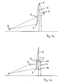
- Fig. 1 shows a wind turbine with tower 4 and nacelle 5 and two rotor blades 6 and 7.
- a non-contact distance measuring system 3 aligned with a first measuring point 1 and a second measuring point 2, which are being swept by the rotor blade 6.
- the rotor blades 6 and 7 are rotated so far that the measuring points 1, 2 are then swept by the rotor blade 7.
- Fig. 2 shows a wind turbine that in Fig. 1 However, with a arranged about 100 m in front of the wind turbine measuring system 3, which is aligned to a first measuring point 1 and to a second measuring point. 2
- Fig. 3 shows a view of a rotor blade 6 with indicated by dashed lines profile lines 8 and 9. These profile lines 8 and 9 are slightly curved over the rotor blade 6. This is because the rotor blade 6 rotates in a circle around the hub, while the measuring points are fixed in place ,
- Fig. 4a shows a wind turbine as in Fig. 1 and 2 , but with two non-contact measuring systems 3, each aligned with a first measuring point 1 and a second measuring point 2.
- the non-contact measuring system 3 which is arranged on the nacelle 5, oriented upward, while the non-contact measuring system 3, before the system is positioned at the bottom of the plane of rotation.
- Fig. 4b shows a wind turbine with tower 4 with non-contact distance measuring system 3.
- the non-contact distance measuring system 3 is aligned to two measuring points 1, 2. If no rotor blade 6, 7 obstructs the view of the tower 4, the contactless distance measuring system 3 measures the tower 4 at the tower measuring points 10. As a result, the inclination of the tower and the distance between the tower 4 and the contactless distance measuring system 3 can be determined.
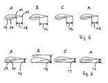
- Fig. 5 shows prepared measurement data of a non-contact distance measuring system. Shown are profile data for the rotor blades A, B, C and once again for the rotor blade A. The rotor blades A, B, C, A have passed through the corresponding measuring points one after the other and two profile lines 19, 20 of each rotor blade were received. These are shown superimposed here and is the distance of the trailing edge 11 of the individual profile lines 19, 20. This is the edgewise bending 12. It can be seen that they look very similar to the rotor blades A, B, A. Only rotor blade B falls clearly out of the frame. It can be seen that the rotor blade B deviates significantly in its rigidity or its arrangement in the rotor.
- Fig. 6 again shows in each case two profile lines 19, 20 of the rotor blades A, B, C, A, and it is the maximum tread depth 13 is characterized, which provides information about the flapwise bending.
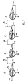
- Fig. 7 shows in each case three profile lines of the rotor blades A, B, C, A.
- Darin is a circle 15 to the calculated pitch axis. Furthermore drawn in are the positioning lines of the individual profiles. An angle of attack or pitch 17 has been drawn.
- the graduation 14 as well as the maximum tread depth 13 and a distance 16 to a predefined point / a predefined plane were identified.
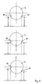
- Fig. 8 shows three views of a cross section through a tower with dashed lines of measurement, which impinge on tower measurement points 10. Also marked is a cross in the tower cross section, the indicates the rest position of the tower. In the upper figure, the tower is in the rest position. Both tower measuring points 10 have the same distance to the distance measuring device. In the middle picture of the Fig. 8 the tower is moved away from the rangefinder. As a result, the tower measuring points 10 have shifted to the rear, which can be detected.
- Fig. 9 shows a tower cross-section through a tower 4 with a rest position indicating cross as in Fig. 8 ,
- the first profile line 19 was used for the measurement
- the second profile line 20 was used for the measurement
- the absolute distance 16 and the distance between the rear edge 11 and the same reference point / plane are indicated as well as the profile depth of the respective profile.
- Fig. 10 shows measured values over a profile line via a rotor blade. Numerous revolutions of the rotor at one measuring point were used to record numerous profiles over the profile line and display them together. Shown is on the horizontal axis, the extension of the rotor blade in the plane of rotation in the direction of rotation, ie the profile line, and on the vertical axis, the distance of the surface of the rotor blade to the distance measuring system, so the profile. Before further analysis, it is advisable to perform an averaging via statistical methods. In the simplest case, the arithmetic mean of the distance is calculated at each point of the profile line.
Description
Die vorliegende Erfindung betrifft ein Messverfahren zur Kontrolle und/oder Optimierung von Windenergieanlagen mit einem berührungslosen Abstandmesssystem.The present invention relates to a measuring method for controlling and / or optimizing wind turbines with a non-contact distance measuring system.
Derartige Systeme sind aus dem Stand der Technik bekannt, um beispielsweise eine Kollision eines Rotorblattes mit einem Turm zu verhindern. Auch ist es beispielsweise bekannt, ein Profil über ein Rotorblatt aufzunehmen. So lehrt die
Derartige Messverfahren sind jedoch nur in der Lage, ganz gezielt einzelne sehr wesentliche Parameter für den Betrieb der Windenergieanlage zu ermitteln und insbesondere deren gefahrlosen Betrieb sicherzustellen.However, such measuring methods are only able to determine very specific individual very significant parameters for the operation of the wind turbine and in particular to ensure their safe operation.
Aufgabe der vorliegenden Erfindung ist es, ein Messverfahren anzugeben, das detaillierte Aussagen über den Zustand zumindest eines Rotorblattes erlaubt und dadurch eine Optimierung der Betriebsweise der Windenergieanlage bzw. ein frühzeitiges Erkennen von Materialfehlern oder Materialabweichungen ermöglicht.Object of the present invention is to provide a measuring method that allows detailed statements about the state of at least one rotor blade and thereby optimizes the operation of the wind turbine or an early detection of material defects or deviations in material allows.
Gelöst wird diese Aufgabe durch ein Messverfahren gemäß Anspruch 1 sowie durch eine Windenergieanlage gemäß Anspruch 10. Die abhängigen Unteransprüche 2 bis 9 geben vorteilhafte Weiterbildungen an.This object is achieved by a measuring method according to
Ein erfindungsgemäßes Messverfahren zur Kontrolle und/oder Optimierung von Windenergieanlagen, aufweisend mindestens ein längliches, an einer Nabe gelagertes Rotorblatt, umfasst das Ausrichten eines berührungslosen Abstandsmesssystems auf mindestens zwei Messpunkte, die von dem mindestens einem Rotorblatt überstrichen werden und unterschiedliche Abstände zur Nabe aufweisen. Dabei ist das berührungslose Abstandsmesssystem geeignet, an verschiedenen Messpunkten um maximal 200 Millisekunden zeitversetzt Abstände zu erfassen.An inventive measuring method for controlling and / or optimizing wind turbines, comprising at least one elongated rotor blade mounted on a hub, comprises aligning a non-contact distance measuring system with at least two measuring points which are swept by the at least one rotor blade and have different distances from the hub. That's it Non-contact distance measuring system suitable for detecting distances at different measuring points by a maximum of 200 milliseconds.
Das Verfahren umfasst weiter das Bestimmen von mindestens zwei Profilen über das mindestens eine Rotorblatt entlang jeweils einer Profillinie, wobei die mindestens zwei Profillinien über die Punkte des Rotorblattes verlaufen, die die mindestens zwei Messpunkte überstreichen.The method further comprises determining at least two profiles over the at least one rotor blade along in each case one profile line, wherein the at least two profile lines extend over the points of the rotor blade, which cover the at least two measuring points.
Somit werden über das Verfahren mindestens zwei Profile über mindestens zwei Profillinien über das mindestens eine Rotorblatt erfasst. Über solche mindestens zwei Profillinien lassen sich zahlreiche Aussagen über den Betriebszustand bzw. das Rotorblatt generieren, wie die weiteren Ausführungen beispielhaft aufzeigen. Auch ist eine Diagnose von Fehlern der Fertigung und des Aufbaus möglich. Dabei sind die Aussagen, die auf mindestens zwei Profillinien basieren, denen, die allein auf einzelnen Abstandsmessungen bzw. auf einem einzelnen Profil über ein Rotorblatt fußen, deutlich überlegen. So kann auf einfache Weise eine sehr aussagekräftige Datenbasis über ein Rotorblatt bzw. den Betriebszustand gewonnen werden.Thus, at least two profiles over at least two profile lines on the at least one rotor blade are detected by the method. By means of such at least two profile lines, numerous statements can be generated about the operating state or the rotor blade, as the further explanations show by way of example. It is also possible to diagnose manufacturing and assembly errors. The statements, which are based on at least two profile lines, are clearly superior to those based solely on individual distance measurements or on a single profile via a rotor blade. In this way, a very meaningful data base about a rotor blade or the operating state can be obtained in a simple manner.
Dabei kann eine berührungslose Abstandsmessung beispielsweise über einen Laser durchgeführt werden. Denkbar ist hier eine Laufzeitmessung durchzuführen. Dabei kann das berührungslose Abstandsmesssystem dadurch zur zeitversetzten Erfassung an den mindestens zwei Messpunkte ausgerüstet werden, dass es über kipp- und/oder schwenkbare Spiegel zur entsprechenden Ablenkung des Laserstrahls verfügt. Alternativ können auch mehrere Laser mit entsprechenden Messsystemen zur Abstandsmessung vorgesehen werden, so dass die Messungen gleichzeitig durchgeführt werden können.In this case, a non-contact distance measurement can be carried out for example via a laser. It is conceivable here to perform a transit time measurement. In this case, the non-contact distance measuring system can thereby be equipped for time-shifted detection at the at least two measuring points that it has tiltable and / or pivotable mirror for the corresponding deflection of the laser beam. Alternatively, it is also possible to provide a plurality of lasers with corresponding measuring systems for distance measurement, so that the measurements can be carried out simultaneously.
Bei der zeitversetzten Erfassung an zwei Messpunkten mit höchsten 200 Millisekunden Abstand zur Erfassung von zwei Profilen, kommt es darauf an, dass bei der Passage eines Rotorblattes ausreichend viele Messpunkte genommen werden können, um ein aussagekräftige Profile zu erstellen. Dies ist bei üblichen Betriebsbedingungen einer Windenergieanlage dann gegeben, wenn die Messung an zwei Messpunkten in einem Abstand von höchsten 200 Millisekunden erfolgen kann. Bei Windenergieanlagen mit hohen Rotationsgeschwindigkeiten bzw. langen Flügellängen kann eine deutlich schnellere Erfassung notwendig sein, insbesondere dann, wenn Profillinien am äußeren Ende der Rotorblätter erfasst werden sollen. Hier kann eine zeitversetzte Messung mit höchsten 5 Millisekunden Zeitverzögerung angebracht sein. Je mehr Messwerte pro Profil erfasst werden sollen, umso schneller müssen derartige Messungen erfolgen. In der Regel werden mindestens 10 Messwerte pro Profil erfasst werden müssen, um eine aussagekräftiges Profil erzeugen zu können. Werden mehr als zwei Profillinien erfasst, ist der Abstand der Messungen entsprechend kleiner zu wählen. Die genannte Bedingung kann in der Regel dann erfüllt werden, wenn pro zu erfassendem Profil innerhalb von 200 ms eine Messung durchgeführt werden kann. Wie oben beschrieben kann das Zeitintervall bei besonderen Anlagen oder weit außen am Rotorblatt liegenden Profillinien deutlich geringer zu wählen sein.In the time-delayed detection at two measuring points with a maximum of 200 milliseconds distance to the detection of two profiles, it is important that when passing a rotor blade enough measuring points can be taken to create a meaningful profile. This is under normal operating conditions Wind turbine given when the measurement can be done at two measuring points at a distance of 200 milliseconds maximum. In wind turbines with high rotational speeds or long wing lengths, a much faster detection may be necessary, especially if profile lines are to be detected at the outer end of the rotor blades. Here, a time-delayed measurement with a maximum delay of 5 milliseconds may be appropriate. The more measured values per profile are to be acquired, the faster such measurements must take place. As a rule, at least 10 measured values per profile must be recorded in order to generate a meaningful profile. If more than two profile lines are recorded, the distance of the measurements must be correspondingly smaller. The stated condition can usually be met if a measurement can be carried out per profile to be detected within 200 ms. As described above, the time interval for special systems or profile lines lying far outside the rotor blade can be chosen to be significantly lower.
Unter einem Messpunkt ist hier die Ausrichtung des berührungslosen Abstandmesssystems in einer Richtung zu verstehen, die vom Rotorblatt gekreuzt wird. Der Messpunkt ist somit nicht ein realer Punkt des Rotorblatts, sondern vielmehr eine Linie, in der das Abstandmesssystem ausgerichtet ist und die vom Rotorblatt gekreuzt wird. Die Punkte der Oberfläche des Rotorblatts, die die Linie kreuzen bilden eine Profillinie, auf der die einzelnen Abstandsmessungen vorgenommen werden.A measuring point here is to be understood as the orientation of the non-contact distance measuring system in one direction, which is crossed by the rotor blade. The measuring point is thus not a real point of the rotor blade, but rather a line in which the distance measuring system is aligned and which is crossed by the rotor blade. The points of the surface of the rotor blade that cross the line form a profile line on which the individual distance measurements are made.
Vorteilhafter Weise sind die mindestens zwei Messpunkte so gewählt, dass sie gleichzeitig vom Rotorblatt überstrichen werden. Hat das Rotorblatt an den unterschiedlichen Messpunkten aufgrund seiner Umfanggeschwindigkeit und Breite verschiedene Passagezeiten, so reicht es aus, wenn die Messpunkte zu einem Zeitfenster vom Rotorblatt gleichzeitig überstrichen werden. Vorteilhafter Weise liegen mindestens zwei Messpunkte auf einer Linie ausgehend von der Nabe.Advantageously, the at least two measuring points are selected so that they are simultaneously swept by the rotor blade. If the rotor blade has different passage times at the different measuring points due to its peripheral speed and width, it is sufficient if the measuring points are simultaneously swept over at a time window by the rotor blade. Advantageously, at least two measuring points lie on a line starting from the hub.
Vorteilhafter Weise wird das Messverfahren so durchgeführt, dass über jedes Rotorblatt zumindest zwei Profile mit unterschiedlichem Abstand zur Nabe aufgenommen werden. Dabei werden diese Profile vorteilhafter Weise an den gleichen mindestens zwei Messpunkten mit unterschiedlichem Abstand zur Nabe genommen. Somit werden die Profile über die verschiedenen Rotorblätter zeitversetzt bei der jeweiligen Passage über die Messpunkte genommen.Advantageously, the measuring method is carried out such that over each rotor blade at least two profiles with different distances to Hub to be included. In this case, these profiles are advantageously taken at the same at least two measuring points at different distances from the hub. Thus, the profiles are taken over the different rotor blades with a time offset at the respective passage over the measuring points.
Mit Vorteil werden bei mehreren Umdrehungen des Rotors pro Rotorblatt und pro Profillinie mehrere Profile aufgenommen und bei zumindest ähnlichen Betriebsbedingungen der Windenergieanlage jeweils über die Profile einer Profillinie eines Rotorblattes gemittelt bevor darauf basierend weitere Analysen durchgeführt beziehungsweise Aussagen generiert werden.Advantageously, several profiles are recorded at several revolutions of the rotor per rotor blade and per profile line and averaged at least similar operating conditions of the wind turbine on the profiles of a profile line of a rotor blade before based on further analyzes carried out or statements are generated.
Mit besonderem Vorteil umfasst das Messverfahren das Ermitteln mindestens einer Biegung, Steifigkeit und/oder Torsion des mindestens einen Rotorblattes auf Basis der mindestens zwei Profile mit unterschiedlichem Abstand zur Nabe.With particular advantage, the measuring method comprises determining at least one bending, rigidity and / or torsion of the at least one rotor blade on the basis of the at least two profiles with different distances from the hub.
Bei einer solchen Verwendung der ursprünglichen Messdaten zur Ermittlung dieser Eigenschaften kommen die Vorteile des erfindungsgemäßen Verfahren besonders deutlich zu tage.With such a use of the original measurement data to determine these properties, the advantages of the method according to the invention become particularly apparent.
Beispielsweise bezüglich der Steifigkeit kann bei einer Abstandsmessung lediglich an einem Punkt nur eine sehr generelle Aussage über die Steifigkeit des Rotorblattes getroffen werden. Bei einer Erfassung von mindestens zwei Profilen mit unterschiedlichem Abstand zur Nabe kann bezüglich der Steifigkeit sowohl eine Aussage in den verschiedenen Richtungen der möglichen Biegung bzw. Torsion des Rotorblattes generiert werden als auch verschiedene Aussagen bezüglich verschiedener Abschnitte des Rotorblattes.For example, with respect to rigidity, only a very general statement about the stiffness of the rotor blade can be made at a distance measurement at only one point. In the case of a detection of at least two profiles with different distances from the hub, it is possible with respect to the stiffness to generate a statement in the various directions of the possible bending or torsion of the rotor blade as well as different statements regarding different sections of the rotor blade.
Besonders vorteilhaft weist das erfindungsgemäße Messverfahren den Schritt auf, dass die edgewise und/oder flapwise Biegung des mindestens einen Rotorblattes zwischen den mindestens zwei Profilen bestimmt wird. Unter der edgewise Biegung ist die Biegung des Rotorblattes innerhalb seiner Rotationsebene zu verstehen. Unter der flapwise Biegung ist die Biegung senkrecht dazu zu verstehen.Particularly advantageously, the measuring method according to the invention has the step that the edgewise and / or flapwise bending of the at least one rotor blade between the at least two profiles is determined. The edgewise bending is to be understood as meaning the bending of the rotor blade within its plane of rotation. The flapwise bend is the bend perpendicular to it.
Bei diesen Biegungen handelt es sich um wesentliche Aussagen bezüglich des Rotorblattes und des Betriebszustandes, so dass die durch die Aufnahme von zumindest zwei Profilen mit unterschiedlichem Abstand zur Nabe gesteigerte Genauigkeit des Verfahrens hier besonders zum Tragen kommt.These bends are essential statements regarding the rotor blade and the operating state, so that the increased by the inclusion of at least two profiles with different distance from the hub accuracy of the method is particularly useful here.
Vorteilhafter Weise wird gemäß Anspruch 4 die Torsion zwischen den mindestens zwei Profilen mit unterschiedlichem Abstand zur Nabe bestimmt.Advantageously, the torsion between the at least two profiles is determined at different distances from the hub according to
Die Bestimmung der Torsion bietet nicht nur Aufschluss über die Steifigkeit und den Alterungszustand eines Rotorblattes, sondern stellt auch einen für den Betrieb der Windenergieanlage wichtigen Parameter dar. Denn durch eine solche Torsion besitzt ein Rotorblatt nicht einen generellen Pitchwinkel, sondern einen vom Ort auf dem Rotorblatt abhängigen Pitchwinkel. Da der Pitchwinkel in der Regel ein Parameter der Steuerung der Windenergieanlage ist, bietet es sich hier an, Rücksicht auf die durch Alterung bzw. Windlast auftretenden unterschiedlichen Pitchwinkel über den Blattverlauf zu nehmen und dadurch die Steuerung zu optimieren.The determination of the torsion not only provides information about the stiffness and aging state of a rotor blade, but also represents an important for the operation of the wind turbine parameters. Because such a torsion has a rotor blade not a general pitch angle, but one from the location on the rotor blade dependent pitch angle. Since the pitch angle is usually a parameter of the control of the wind turbine, it is useful here to take account of the different pitch angles occurring due to aging or wind load over the course of the blade, thereby optimizing the control.
Vorteilhafterweise wird gemäß Anspruch 5 auf Basis mindestens eines Profils die Pitchachse des Rotorblattes bestimmt. Aufgrund des Profils kann beispielsweise aufgrund von Herstellerdaten oder von vorherigen Messungen die Pitchachse des Blattes bestimmt werden. Dies kann beispielsweise durch Ermittlung von zwei Fixpunkten auf dem Profil erfolgen, die eine bekannte Lage zur Pitchachse aufweisen.Advantageously, the pitch axis of the rotor blade is determined on the basis of at least one profile according to
Die Bestimmung der Pitchachse bietet eine überraschend gute Bezugsgröße, um verschiedene Profile über ein Rotorblatt miteinander zu vergleichen. Bei einer solchen Darstellung bzw. eine darauf bezogene Berechnung können Abweichungen vom Sollzustand besonders deutlich erkannt werden.The determination of the pitch axis offers a surprisingly good reference value for comparing different profiles via a rotor blade. In such a representation or a related calculation deviations from the nominal state can be detected particularly clearly.
Dabei werden die einzelnen Profile so übereinander gelegt, dass ihre Pitchachsen übereinander liegen. Sodann kann beispielsweise der Anstellwinkel der einzelnen Profile zueinander bestimmt werden.The individual profiles are superimposed so that their pitch axes are superimposed. Then, for example, the angle of attack of the individual profiles are determined to each other.
Vorteilhafter Weise wird der Konuswinkel des mindestens einen Rotorblattes bestimmt. Unter Konuswinkel ist der Winkel eines Rotorblatts zu verstehen, der zwischen der Längsachse des Rotorblatt und einer auf der Rotordrehachse senkrechten Ebene eingeschlossen wird.Advantageously, the cone angle of the at least one rotor blade is determined. Under cone angle is the angle of a rotor blade to be understood, which is enclosed between the longitudinal axis of the rotor blade and a plane perpendicular to the rotor axis of rotation.
Eine solche Bestimmung des Konuswinkels bietet die Möglichkeit, andere Daten unabhängig von Fehlern im Konuswinkel miteinander zu vergleichen.Such a determination of the cone angle offers the possibility of comparing other data independently of errors in the cone angle.
Vorteilhafter Weise wird, wenn die Windenergieanlage mindestens zwei Rotorblätter umfasst, die Teilung, insbesondere die Abweichung von der vorgesehenen Teilung, bestimmt. Unter der Teilung ist die Verteilung der Rotorblätter auf die Rotationsebene, also die Verteilung der Rotorblätter im Kreis zu verstehen.Advantageously, if the wind turbine comprises at least two rotor blades, the pitch, in particular the deviation from the intended pitch, determined. The division is the distribution of the rotor blades on the plane of rotation, so to understand the distribution of the rotor blades in a circle.
Bei drei Rotorblättern wird in der Regel eine Teilung von 120° vorgesehen. Im Betrieb kann es jedoch zu Abweichungen kommen, die beispielsweise eine Unwucht hervorrufen können. Solche können durch das beschriebene Verfahren besonders leicht erfasst werden, da nach Vermessen des Profils die Hinterkante des Rotorblattes besonders einfach und zuverlässig bestimmbar ist.With three rotor blades, a pitch of 120 ° is usually provided. In operation, however, there may be deviations that can cause, for example, an imbalance. Such can be detected particularly easily by the method described, since after measuring the profile, the trailing edge of the rotor blade is particularly simple and reliable determinable.
In einer vorteilhaften Ausführung wird, wenn die Windenergieanlage eine Gondel umfasst, das Abstandsmesssystem auf der Gondel positioniert. Bei einer solchen Positionierung ist es vorteilhaft, auch die Turmschwingungen zu erfassen. Dies ist beispielsweise durch Schwingungssensoren möglich. Denn Turmschwingungen wirken sich auch auf die Rotorblätter aus und können vorteilhafter Weise mit in die Berechnung einbezogen werden. Soll beispielsweise die Steifigkeit eines Rotorblattes bestimmt werden, können die durch die Turmschwingungen hervorgerufenen Verformungen herausgerechnet oder besonders beurteilt werden.In an advantageous embodiment, if the wind turbine comprises a nacelle, the distance measuring system is positioned on the nacelle. In such a positioning, it is advantageous to detect the tower vibrations. This is possible for example by vibration sensors. Because tower vibrations also affect the rotor blades and can advantageously be included in the calculation. If, for example, the stiffness of a rotor blade is to be determined, the deformations caused by the tower vibrations can be calculated out or specially assessed.
In einer anderen Ausführung wird das Abstandsmesssystem entfernt von der Windenergieanlage und vor der Windenergieanlage positioniert. Vor der Windenergieanlage bedeutet, dass es mit Blick auf die Nabe der Windenergieanlage, bei optimaler Ausrichtung der Windenergieanlage also auf der Luvseite, angeordnet ist. Dies bedeutet jedoch, dass die Windenergieanlage während der Messung in eine Richtung ausgerichtet sein muss. Die Durchführung des Verfahrens auf diese Art bietet sich insbesondere dann an, wenn nur zu vereinzelten Zeitpunkten entsprechende Messungen durchgeführt werden sollen.In another embodiment, the distance measuring system is positioned away from the wind turbine and in front of the wind turbine. Before the wind turbine means that it is located with a view to the hub of the wind turbine, with optimal orientation of the wind turbine so on the windward side. However, this means that the wind turbine must be aligned in one direction during the measurement. The implementation of the method in this way offers itself especially if only at isolated times appropriate measurements should be performed.
Dabei ist es besonders vorteilhaft, wenn der Abstand des Messsystems zur Nabe bestimmt und/oder der Abstand zu einem Punkt des Turms und die Neigung des Turms gemessen werden. Durch eine solche Bestimmung des Abstandes sind auch absolute Aussagen über die Rotorblätter möglich bzw. können Turmschwingungen, die bei einem vor der Windanlage positionierten System deutlich größere Auswirkungen haben, herausgerechnet werden. Dabei können der Abstand zur Nabe oder zum Turm und die Neigung des Turmes auf verschiedene Weise bestimmt werden. Beispielsweise ist es vorstellbar, die Abstände mit dem gleichen Abstandsmesssystem zu erfassen. Auch kann die Neigung des Turmes durch zwei Abstandsmessungen an unterschiedlichen Höhen des Turmes erzielt werden.It is particularly advantageous if the distance of the measuring system determines the hub and / or the distance to a point of the tower and the inclination of the tower are measured. By such a determination of the distance and absolute statements about the rotor blades are possible or can tower vibrations, which have significantly greater impact in a positioned in front of the wind turbine system, are excluded. The distance to the hub or to the tower and the inclination of the tower can be determined in different ways. For example, it is conceivable to detect the distances with the same distance measuring system. Also, the inclination of the tower can be achieved by two distance measurements at different heights of the tower.
Auch kann mit Vorteil eine Erfassung von mindestens zwei Profilen jeweils von vor der Windenergieanlage und von der Gondel aus durchgeführt werden. Die Vermessung der Lage des Turms an einer Höhe kann insbesondere bei runden oder ovalen Formen durch zwei auf eine Höhe des Turms gerichtete Abstandsmesssysteme oder eines zur entsprechend zeitversetzten Erfassung erfolgen. Dabei werden die Abstände an zwei auf den Turm auf gleicher Höhe gerichtete Messlinien bestimmt. Bewegt sich der Turm vom Messsystem weg vergrößern sich beide Abstände, verlagert er sich zur Seite, vergrößert sich aufgrund der runden/ovalen Turmform einer, während der andere sich verkleinert.It can also be advantageously carried out a detection of at least two profiles in each case before the wind turbine and from the nacelle. The measurement of the position of the tower at a height can be carried out in particular for round or oval shapes by two directed to a height of the tower distance measuring systems or a correspondingly time-delayed detection. The distances are determined by two measuring lines directed to the tower at the same height. If the tower moves away from the measuring system, both distances increase, it shifts to the side, increases due to the round / oval tower shape one, while the other is smaller.
Eine erfindungsgemäße Windenergieanlage weist ein Messsystem zur Kontrolle und/oder Optimierung der Windenergieanlage auf. Dieses Messsystem umfasst ein berührungsloses Abstandsmesssystem, aufweisend Ausrichtungsmittel zur Ausrichtung auf mindestens zwei Messpunkte mit unterschiedlichem Abstand zur Nabe, die von dem mindestens einen Rotorblatt überstrichen werden. Das berührungsloses Abstandsmesssystem ist geeignet zur zeitgleichen Erfassung von mindestens zwei Profilen über das mindestens eine Rotorblatt entlang jeweils einer Profillinie durch um maximal 200 Millisekunden zeitversetzte Erfassung von Abständen an den mindestens zwei Messpunkten, wobei die mindestens zwei Profillinien über die Punkte des Rotorblattes verlaufen, die die mindestens zwei Messpunkte überstreichen.A wind energy plant according to the invention has a measuring system for controlling and / or optimizing the wind energy plant. This measuring system comprises a non-contact distance measuring system, comprising alignment means for alignment with at least two measuring points with different distances to the hub, which are swept by the at least one rotor blade. The non-contact distance measuring system is suitable for the simultaneous detection of at least two profiles over the at least one rotor blade along each profile line by a maximum of 200 milliseconds offset in time Detecting distances at the at least two measuring points, wherein the at least two profile lines extend over the points of the rotor blade, which cover the at least two measuring points.
Eine solche Windenergieanlage ist ausgerüstet mit einem System zur Durchführung des erfindungsgemäßen Verfahrens. Die weiteren vorteilhaften Ausbildungen der Unteransprüche 2 bis 9 können hier entsprechend umgesetzt werden.Such a wind turbine is equipped with a system for carrying out the method according to the invention. The further advantageous embodiments of the
Wird eine Windenergieanlage mit einem solchen System ausgestattet, können die entsprechenden Messungen im kontinuierlichen Betrieb durchgeführt werden und somit entscheidende Daten zur Optimierung der Windenergieanlage bei verschiedenen Windrichtungen und Lastsituationen gewonnen werden. Darüber hinaus ist eine kontinuierliche Kontrolle der Rotorblätter und ein frühzeitiges Erkennen von erwarteten Strukturwerten möglich. Auch ist eine Diagnose von Fehlern der Fertigung und des Aufbaus möglich.If a wind turbine is equipped with such a system, the corresponding measurements can be carried out in continuous operation and thus crucial data for optimization of the wind turbine can be obtained in different wind directions and load situations. In addition, a continuous control of the rotor blades and an early detection of expected structural values is possible. It is also possible to diagnose manufacturing and assembly errors.
Weitere vorteilhafte Ausführungsformen und Vorteile sollen im Folgenden anhand von schematischen Zeichnungen beschrieben werden. Die Figuren zeigen im Einzelnen:
-
Fig. 1 eine Ansicht einer Windenergieanlage mit erfindungsgemäßem Abstandsmesssystem, positioniert auf einer Gondel; -
Fig. 2 eine Ansicht einer Windenergieanlage mit erfindungsgemäßem Abstandsmesssystem, positioniert vor der Windenergieanlage; -
Fig. 3 eine Ansicht eines Flügels mit zwei Profillinien; -
Fig. 4a eine Ansicht einer Windenergieanlage mit einem alternativen Messsystem; -
Fig. 4b eine Ansicht einer Windenergieanlage mit einer weiteren alternativen Messanordnung; -
Fig. 5 eine Ansicht der edgewise Biegung; -
Fig. 6 eine Ansicht der flapwise Biegung; -
Fig. 7 eine detaillierte Vermessung mit drei Profilen; -
Fig. 8 eine Ansicht der Turmvermessung; -
Fig. 9 eine Ansicht der Vermessung relativ zum Turm mit zwei Profilen; und -
Fig. 10 eine Ansicht von Messwerten.
-
Fig. 1 a view of a wind turbine with inventive distance measuring system, positioned on a nacelle; -
Fig. 2 a view of a wind turbine with inventive distance measuring system, positioned in front of the wind turbine; -
Fig. 3 a view of a wing with two profile lines; -
Fig. 4a a view of a wind turbine with an alternative measuring system; -
Fig. 4b a view of a wind turbine with a further alternative measuring arrangement; -
Fig. 5 a view of the edgewise bend; -
Fig. 6 a view of the flapwise bend; -
Fig. 7 a detailed survey with three profiles; -
Fig. 8 a view of the tower measurement; -
Fig. 9 a view of the survey relative to the tower with two profiles; and -
Fig. 10 a view of readings.
Zu erkennen sind in einer solchen Darstellung nicht nur die Abweichung der Teilung und Unterschiede in der maximalen Profiltiefe, sondern beispielsweise auch sehr deutlich Torsionen im Rotorblatt, die sich dadurch zeigen, dass die Anstellwinkel der einzelnen Profillinien eines Rotorblattes deutlich unterschiedlich ausfallen.Not only the deviation of the pitch and differences in the maximum tread depth can be seen in such a representation, but also, for example, very clearly torsions in the rotor blade, which show that the angles of attack of the individual profile lines of a rotor blade are significantly different.
In der unteren Darstellung der
Durch eine solche Vermessung an zwei Punkten eines Querschnitts lässt sich somit die Bewegung des Turmes in der entsprechenden Ebene erfassen.By such a survey at two points of a cross section can thus detect the movement of the tower in the corresponding plane.
In einer solchen Darstellung lässt sich nicht nur die Verbiegung des Rotorblattes ermitteln, sondern auch seine Lage relativ zum Turm 4 erfassen.In such an illustration, not only the bending of the rotor blade can be determined, but also detect its position relative to the
Weitere vorteilhafte Ausbildungen lassen sich durch den Fachmann für den jeweiligen Anwendungszweck angepasst leicht auffinden.Further advantageous embodiments can be achieved by the person skilled in the art adapted to the respective application easily find.
- 1.1.
- Erster MesspunktFirst measuring point
- 2.Second
- Zweiter MesspunktSecond measuring point
- 3.Third
- AbstandsmesssystemDistance measuring system
- 4.4th
- Turmtower
- 5.5th
- Gondelgondola
- 6.6th
- Erstes RotorblattFirst rotor blade
- 7.7th
- Zweites RotorblattSecond rotor blade
- 8.8th.
- Erste ProfillinieFirst profile line
- 9.9th
- Zweite ProfillinieSecond profile line
- 10.10th
- Messpunkt auf TurmMeasuring point on tower
- 11.11th
- Hinterkantetrailing edge
- 12.12th
- Edgewise VerbiegungEdgewise bending
- 13.13th
- Maximale ProfiltiefeMaximum tread depth
- 14.14th
- Teilungdivision
- 15.15th
- Kreis um DrehachseCircle around axis of rotation
- 16.16th
- Abstanddistance
- 17.17th
- Pitchpitch
- 18.18th
- Profiltiefetread depth
- 19.19th
- Erstes ProfilFirst profile
- 20.20th
- Zweites ProfilSecond profile
- 21.21st
- Abstand der HinterkanteDistance of the trailing edge
- AA
- Rotorblatt ARotor blade A
- BB
- Rotorblatt BRotor blade B
- CC
- Rotorblatt CRotor blade C
Claims (10)
- A measurement method for controlling and/or optimizing wind power plants, having at least one longitudinally extended rotor blade (6, 7) mounted on a hub, comprisinga. aligning a contactless distance measuring system (3) suited for measuring, offset in time by a maximum of 200 ms, at least two distances (16) at different points, on at least two measurement points (1, 2), which are swept over by the at least one rotor blade (6, 7) and have different distances (16) to the hub;b. determining at least two profiles (19, 20) using the at least one rotor blade (6, 7) along each profile line (8, 9), wherein the at least two profile lines (8, 9) run over the points of the rotor blade (6, 7), which sweep over the at least two measurement points (1, 2).
- The measurement method according to claim 1 further comprising determining at least one curvature, stiffness and/or torsion (12) of the at least one rotor blade (6, 7) based on the at least two profiles (19, 20).
- The measurement method according to one of the preceding claims, wherein the edge wise and/or flap wise curvature (12) of the at least one rotor blade (6, 7) is determined between the at least two profiles (19, 20).
- The measurement method according to one of the preceding claims, wherein the torsion is determined between the at least two profiles (19, 20).
- The measurement method according to one of the preceding claims, wherein the pitch axis (17) of the rotor blade (6, 7) is determined based on at least one profile (19, 20).
- The measurement method according to one of the preceding claims, wherein the cone angle of the at least rotor blade (6, 7) is determined.
- The measurement method according to one of the preceding claims, wherein the wind power plant comprises at least two rotor blades (6, 7) and the spacing (14), in particular the deviation, from a predefined spacing (14), is determined.
- The measurement method according to one of the preceding claims, wherein the wind power plant comprises a nacelle (5) and the distance measuring system (3) is positioned on the nacelle (5) and in particular also measures tower oscillations.
- The measurement method according to one of the claims 1 to 7, wherein the distance measuring system (3) is positioned removed from the wind power plant, and in particular the distance (16) of the distance measuring system (3) to the hub and/or to a point of the tower (10) and the inclination of the tower (4) is also determined.
- A wind power plant having at least one longitudinally extended rotor blade (6, 7) mounted on a hub, and containing a measurement system for controlling and/or optimizing the wind power plant, comprising a contactless distance measuring system (3),a. having aligning means for the alignment of at least two measurement points (1, 2) with different distance (16) to the hub that are swept over by the at least one rotor blade (6, 7), andb. suited for simultaneously measuring at least two profiles (19, 20) over the at least one rotor blade (6, 7) along each profile line (8, 9), by measuring, offset in time by a maximum of 200 ms, at least two distances (16) at the at least two measurement points (1, 2), wherein the at least two profiles lines (8, 9) run over the points of the rotor blade (6, 7) which sweep over the at least two measurement points (1, 2).
Applications Claiming Priority (2)
| Application Number | Priority Date | Filing Date | Title |
|---|---|---|---|
| DE102010024532A DE102010024532B4 (en) | 2010-06-21 | 2010-06-21 | Measuring method for controlling and / or optimizing wind turbines with a non-contact distance measuring system |
| PCT/EP2011/060241 WO2011161058A1 (en) | 2010-06-21 | 2011-06-20 | Measurement method for monitoring and/or optimizing wind power plants having a non-contacting distance measurement system |
Publications (2)
| Publication Number | Publication Date |
|---|---|
| EP2582970A1 EP2582970A1 (en) | 2013-04-24 |
| EP2582970B1 true EP2582970B1 (en) | 2014-04-02 |
Family
ID=44546346
Family Applications (1)
| Application Number | Title | Priority Date | Filing Date |
|---|---|---|---|
| EP11735609.7A Active EP2582970B1 (en) | 2010-06-21 | 2011-06-20 | Measurement method for monitoring and/or optimizing wind power plants having a non-contacting distance measurement system |
Country Status (4)
| Country | Link |
|---|---|
| EP (1) | EP2582970B1 (en) |
| DE (1) | DE102010024532B4 (en) |
| ES (1) | ES2468917T3 (en) |
| WO (1) | WO2011161058A1 (en) |
Families Citing this family (9)
| Publication number | Priority date | Publication date | Assignee | Title |
|---|---|---|---|---|
| DE102013201163A1 (en) * | 2013-01-24 | 2014-08-07 | Wobben Properties Gmbh | Method for measuring a rotor blade angle |
| EP2873854A1 (en) * | 2013-11-14 | 2015-05-20 | Siemens Aktiengesellschaft | Method to determine a distance between a tower wall and a wind turbine blade |
| DE102015121981A1 (en) * | 2015-12-16 | 2017-06-22 | fos4X GmbH | Method and device for operating a wind turbine |
| CN106286152B (en) * | 2016-09-14 | 2018-12-04 | 北京金风科创风电设备有限公司 | The blade state monitoring device and monitoring method of wind power generating set |
| CN106289114A (en) * | 2016-10-19 | 2017-01-04 | 吴尧增 | A kind of method that indirect type fan rotor geometric parameter measurement and performance optimize |
| EP4191058B1 (en) * | 2017-12-29 | 2024-03-13 | Windcomp GmbH | Method for measuring imbalances and angles of attack and half-profiles |
| CN111102940B (en) * | 2018-10-29 | 2022-07-05 | 北京金风科创风电设备有限公司 | Blade pitch angle deviation detection method, device, storage medium and system |
| CN113107784B (en) * | 2021-04-08 | 2022-05-17 | 中国华能集团清洁能源技术研究院有限公司 | Laser correction method, device, equipment and medium for wind turbine generator blade angle |
| CN113153656B (en) * | 2021-05-26 | 2024-04-19 | 三一重能股份有限公司 | Tower clearance monitoring system and monitoring method of fan |
Family Cites Families (4)
| Publication number | Priority date | Publication date | Assignee | Title |
|---|---|---|---|---|
| DE10032314C1 (en) | 2000-07-04 | 2001-12-13 | Aloys Wobben | Rotor blade angle evaluation method for wind-powered energy plant uses processor supplied with data for measured distance between rotor blade and mast of energy plant |
| DE102005048805A1 (en) * | 2005-10-10 | 2007-04-12 | Daubner & Stommel GbR Bau-Werk-Planung (vertretungsberechtigter Gesellschafter: Matthias Stommel, 27777 Ganderkesee) | Method for operating a wind energy plant |
| DE102006054667B4 (en) * | 2006-11-17 | 2011-02-17 | Windcomp Gmbh | Collision Warning System for a Wind Turbine |
| DE102008013392B4 (en) * | 2008-03-10 | 2013-02-07 | Windcomp Gmbh | Method for detecting the tracking of the rotor blades of a wind turbine |
-
2010
- 2010-06-21 DE DE102010024532A patent/DE102010024532B4/en not_active Revoked
-
2011
- 2011-06-20 ES ES11735609.7T patent/ES2468917T3/en active Active
- 2011-06-20 WO PCT/EP2011/060241 patent/WO2011161058A1/en active Application Filing
- 2011-06-20 EP EP11735609.7A patent/EP2582970B1/en active Active
Also Published As
| Publication number | Publication date |
|---|---|
| ES2468917T3 (en) | 2014-06-17 |
| DE102010024532A1 (en) | 2011-12-22 |
| DE102010024532B4 (en) | 2012-04-12 |
| EP2582970A1 (en) | 2013-04-24 |
| WO2011161058A1 (en) | 2011-12-29 |
Similar Documents
| Publication | Publication Date | Title |
|---|---|---|
| EP2582970B1 (en) | Measurement method for monitoring and/or optimizing wind power plants having a non-contacting distance measurement system | |
| EP2337950B1 (en) | Profile of a rotor blade and rotor blade of a wind power plant | |
| EP1994280B1 (en) | Collision warning system for a wind energy installation | |
| EP3913215B1 (en) | Method for measuring a rotor blade angle | |
| EP2582972B1 (en) | Method and device for preventing a lateral oscillation of a wind power installation | |
| EP2929178B1 (en) | Rotor blade trailing edge | |
| WO2013034235A1 (en) | Method and device for determining a yaw angle fault in a wind turbine and wind turbine | |
| EP3803114A1 (en) | Sensor arrangement for a wind turbine | |
| EP2715117A1 (en) | Wind turbine rotor with a pre-bent rotor blade | |
| DE602004001726T2 (en) | Horizontal wave wind turbine and method of measuring the upward flow angle | |
| DE102008031484B4 (en) | Method for determining and readjusting the relative wing setting angle on wind turbines with horizontal drive axles | |
| DE102008013392B4 (en) | Method for detecting the tracking of the rotor blades of a wind turbine | |
| EP2992209B1 (en) | Method and system for monitoring a wind turbine and wind turbine | |
| EP3704374B1 (en) | Swirling element and method for producing a swirling element | |
| DE102018117398A1 (en) | Rotor blade for a wind turbine and wind turbine | |
| EP3732369B1 (en) | Method for measuring imbalances in wind turbine rotors | |
| DE10232021B4 (en) | Method for predicting gusts of wind and the associated control of wind turbines and wind power plant for carrying out this method | |
| DE202008006307U1 (en) | Flange piece and tower for a wind energy plant | |
| DE102013103150A1 (en) | Method for determining an angle of attack | |
| EP3553311B1 (en) | Device and method for controlling a wind turbine | |
| DE102013007744A1 (en) | Wind turbine and process | |
| DE102008032196A1 (en) | Rotor blade monitoring method for wind power plant, involves accomplishing reflection measurement at point of rotor blade, and defining critical deflection values depending on respective wind load and/or power generated by plant |
Legal Events
| Date | Code | Title | Description |
|---|---|---|---|
| PUAI | Public reference made under article 153(3) epc to a published international application that has entered the european phase |
Free format text: ORIGINAL CODE: 0009012 |
|
| 17P | Request for examination filed |
Effective date: 20121214 |
|
| AK | Designated contracting states |
Kind code of ref document: A1 Designated state(s): AL AT BE BG CH CY CZ DE DK EE ES FI FR GB GR HR HU IE IS IT LI LT LU LV MC MK MT NL NO PL PT RO RS SE SI SK SM TR |
|
| DAX | Request for extension of the european patent (deleted) | ||
| GRAP | Despatch of communication of intention to grant a patent |
Free format text: ORIGINAL CODE: EPIDOSNIGR1 |
|
| GRAS | Grant fee paid |
Free format text: ORIGINAL CODE: EPIDOSNIGR3 |
|
| GRAA | (expected) grant |
Free format text: ORIGINAL CODE: 0009210 |
|
| INTG | Intention to grant announced |
Effective date: 20140213 |
|
| AK | Designated contracting states |
Kind code of ref document: B1 Designated state(s): AL AT BE BG CH CY CZ DE DK EE ES FI FR GB GR HR HU IE IS IT LI LT LU LV MC MK MT NL NO PL PT RO RS SE SI SK SM TR |
|
| REG | Reference to a national code |
Ref country code: GB Ref legal event code: FG4D Free format text: NOT ENGLISH |
|
| REG | Reference to a national code |
Ref country code: AT Ref legal event code: REF Ref document number: 660301 Country of ref document: AT Kind code of ref document: T Effective date: 20140415 Ref country code: CH Ref legal event code: EP |
|
| REG | Reference to a national code |
Ref country code: IE Ref legal event code: FG4D Free format text: LANGUAGE OF EP DOCUMENT: GERMAN |
|
| REG | Reference to a national code |
Ref country code: DE Ref legal event code: R096 Ref document number: 502011002627 Country of ref document: DE Effective date: 20140515 |
|
| REG | Reference to a national code |
Ref country code: ES Ref legal event code: FG2A Ref document number: 2468917 Country of ref document: ES Kind code of ref document: T3 Effective date: 20140617 |
|
| RAP2 | Party data changed (patent owner data changed or rights of a patent transferred) |
Owner name: WINDCOMP GMBH |
|
| REG | Reference to a national code |
Ref country code: NL Ref legal event code: VDEP Effective date: 20140402 |
|
| REG | Reference to a national code |
Ref country code: LT Ref legal event code: MG4D |
|
| PG25 | Lapsed in a contracting state [announced via postgrant information from national office to epo] |
Ref country code: BG Free format text: LAPSE BECAUSE OF FAILURE TO SUBMIT A TRANSLATION OF THE DESCRIPTION OR TO PAY THE FEE WITHIN THE PRESCRIBED TIME-LIMIT Effective date: 20140702 Ref country code: GR Free format text: LAPSE BECAUSE OF FAILURE TO SUBMIT A TRANSLATION OF THE DESCRIPTION OR TO PAY THE FEE WITHIN THE PRESCRIBED TIME-LIMIT Effective date: 20140703 Ref country code: IS Free format text: LAPSE BECAUSE OF FAILURE TO SUBMIT A TRANSLATION OF THE DESCRIPTION OR TO PAY THE FEE WITHIN THE PRESCRIBED TIME-LIMIT Effective date: 20140802 Ref country code: CZ Free format text: LAPSE BECAUSE OF FAILURE TO SUBMIT A TRANSLATION OF THE DESCRIPTION OR TO PAY THE FEE WITHIN THE PRESCRIBED TIME-LIMIT Effective date: 20140402 Ref country code: NL Free format text: LAPSE BECAUSE OF FAILURE TO SUBMIT A TRANSLATION OF THE DESCRIPTION OR TO PAY THE FEE WITHIN THE PRESCRIBED TIME-LIMIT Effective date: 20140402 Ref country code: NO Free format text: LAPSE BECAUSE OF FAILURE TO SUBMIT A TRANSLATION OF THE DESCRIPTION OR TO PAY THE FEE WITHIN THE PRESCRIBED TIME-LIMIT Effective date: 20140702 Ref country code: FI Free format text: LAPSE BECAUSE OF FAILURE TO SUBMIT A TRANSLATION OF THE DESCRIPTION OR TO PAY THE FEE WITHIN THE PRESCRIBED TIME-LIMIT Effective date: 20140402 Ref country code: LT Free format text: LAPSE BECAUSE OF FAILURE TO SUBMIT A TRANSLATION OF THE DESCRIPTION OR TO PAY THE FEE WITHIN THE PRESCRIBED TIME-LIMIT Effective date: 20140402 Ref country code: CY Free format text: LAPSE BECAUSE OF FAILURE TO SUBMIT A TRANSLATION OF THE DESCRIPTION OR TO PAY THE FEE WITHIN THE PRESCRIBED TIME-LIMIT Effective date: 20140402 |
|
| PG25 | Lapsed in a contracting state [announced via postgrant information from national office to epo] |
Ref country code: HR Free format text: LAPSE BECAUSE OF FAILURE TO SUBMIT A TRANSLATION OF THE DESCRIPTION OR TO PAY THE FEE WITHIN THE PRESCRIBED TIME-LIMIT Effective date: 20140402 Ref country code: RS Free format text: LAPSE BECAUSE OF FAILURE TO SUBMIT A TRANSLATION OF THE DESCRIPTION OR TO PAY THE FEE WITHIN THE PRESCRIBED TIME-LIMIT Effective date: 20140402 Ref country code: PL Free format text: LAPSE BECAUSE OF FAILURE TO SUBMIT A TRANSLATION OF THE DESCRIPTION OR TO PAY THE FEE WITHIN THE PRESCRIBED TIME-LIMIT Effective date: 20140402 Ref country code: SE Free format text: LAPSE BECAUSE OF FAILURE TO SUBMIT A TRANSLATION OF THE DESCRIPTION OR TO PAY THE FEE WITHIN THE PRESCRIBED TIME-LIMIT Effective date: 20140402 Ref country code: LV Free format text: LAPSE BECAUSE OF FAILURE TO SUBMIT A TRANSLATION OF THE DESCRIPTION OR TO PAY THE FEE WITHIN THE PRESCRIBED TIME-LIMIT Effective date: 20140402 |
|
| PG25 | Lapsed in a contracting state [announced via postgrant information from national office to epo] |
Ref country code: PT Free format text: LAPSE BECAUSE OF FAILURE TO SUBMIT A TRANSLATION OF THE DESCRIPTION OR TO PAY THE FEE WITHIN THE PRESCRIBED TIME-LIMIT Effective date: 20140804 |
|
| REG | Reference to a national code |
Ref country code: DE Ref legal event code: R026 Ref document number: 502011002627 Country of ref document: DE |
|
| PLBI | Opposition filed |
Free format text: ORIGINAL CODE: 0009260 |
|
| PG25 | Lapsed in a contracting state [announced via postgrant information from national office to epo] |
Ref country code: EE Free format text: LAPSE BECAUSE OF FAILURE TO SUBMIT A TRANSLATION OF THE DESCRIPTION OR TO PAY THE FEE WITHIN THE PRESCRIBED TIME-LIMIT Effective date: 20140402 Ref country code: SK Free format text: LAPSE BECAUSE OF FAILURE TO SUBMIT A TRANSLATION OF THE DESCRIPTION OR TO PAY THE FEE WITHIN THE PRESCRIBED TIME-LIMIT Effective date: 20140402 Ref country code: LU Free format text: LAPSE BECAUSE OF FAILURE TO SUBMIT A TRANSLATION OF THE DESCRIPTION OR TO PAY THE FEE WITHIN THE PRESCRIBED TIME-LIMIT Effective date: 20140620 Ref country code: RO Free format text: LAPSE BECAUSE OF FAILURE TO SUBMIT A TRANSLATION OF THE DESCRIPTION OR TO PAY THE FEE WITHIN THE PRESCRIBED TIME-LIMIT Effective date: 20140402 Ref country code: DK Free format text: LAPSE BECAUSE OF FAILURE TO SUBMIT A TRANSLATION OF THE DESCRIPTION OR TO PAY THE FEE WITHIN THE PRESCRIBED TIME-LIMIT Effective date: 20140402 Ref country code: MC Free format text: LAPSE BECAUSE OF FAILURE TO SUBMIT A TRANSLATION OF THE DESCRIPTION OR TO PAY THE FEE WITHIN THE PRESCRIBED TIME-LIMIT Effective date: 20140402 |
|
| REG | Reference to a national code |
Ref country code: CH Ref legal event code: PL |
|
| PLAX | Notice of opposition and request to file observation + time limit sent |
Free format text: ORIGINAL CODE: EPIDOSNOBS2 |
|
| 26 | Opposition filed |
Opponent name: ENERCON GMBH Effective date: 20150105 |
|
| PG25 | Lapsed in a contracting state [announced via postgrant information from national office to epo] |
Ref country code: RS Free format text: LAPSE BECAUSE OF FAILURE TO SUBMIT A TRANSLATION OF THE DESCRIPTION OR TO PAY THE FEE WITHIN THE PRESCRIBED TIME-LIMIT Effective date: 20140716 |
|
| REG | Reference to a national code |
Ref country code: DE Ref legal event code: R026 Ref document number: 502011002627 Country of ref document: DE Effective date: 20150105 |
|
| REG | Reference to a national code |
Ref country code: IE Ref legal event code: MM4A |
|
| PLBP | Opposition withdrawn |
Free format text: ORIGINAL CODE: 0009264 |
|
| PG25 | Lapsed in a contracting state [announced via postgrant information from national office to epo] |
Ref country code: IE Free format text: LAPSE BECAUSE OF NON-PAYMENT OF DUE FEES Effective date: 20140620 Ref country code: LI Free format text: LAPSE BECAUSE OF NON-PAYMENT OF DUE FEES Effective date: 20140630 Ref country code: CH Free format text: LAPSE BECAUSE OF NON-PAYMENT OF DUE FEES Effective date: 20140630 |
|
| REG | Reference to a national code |
Ref country code: FR Ref legal event code: PLFP Year of fee payment: 5 |
|
| PG25 | Lapsed in a contracting state [announced via postgrant information from national office to epo] |
Ref country code: SI Free format text: LAPSE BECAUSE OF FAILURE TO SUBMIT A TRANSLATION OF THE DESCRIPTION OR TO PAY THE FEE WITHIN THE PRESCRIBED TIME-LIMIT Effective date: 20140402 |
|
| PLBD | Termination of opposition procedure: decision despatched |
Free format text: ORIGINAL CODE: EPIDOSNOPC1 |
|
| REG | Reference to a national code |
Ref country code: DE Ref legal event code: R100 Ref document number: 502011002627 Country of ref document: DE |
|
| PG25 | Lapsed in a contracting state [announced via postgrant information from national office to epo] |
Ref country code: MT Free format text: LAPSE BECAUSE OF FAILURE TO SUBMIT A TRANSLATION OF THE DESCRIPTION OR TO PAY THE FEE WITHIN THE PRESCRIBED TIME-LIMIT Effective date: 20140402 |
|
| PG25 | Lapsed in a contracting state [announced via postgrant information from national office to epo] |
Ref country code: SM Free format text: LAPSE BECAUSE OF FAILURE TO SUBMIT A TRANSLATION OF THE DESCRIPTION OR TO PAY THE FEE WITHIN THE PRESCRIBED TIME-LIMIT Effective date: 20140402 |
|
| PLBM | Termination of opposition procedure: date of legal effect published |
Free format text: ORIGINAL CODE: 0009276 |
|
| STAA | Information on the status of an ep patent application or granted ep patent |
Free format text: STATUS: OPPOSITION PROCEDURE CLOSED |
|
| 27C | Opposition proceedings terminated |
Effective date: 20160123 |
|
| REG | Reference to a national code |
Ref country code: FR Ref legal event code: PLFP Year of fee payment: 6 |
|
| PG25 | Lapsed in a contracting state [announced via postgrant information from national office to epo] |
Ref country code: HU Free format text: LAPSE BECAUSE OF FAILURE TO SUBMIT A TRANSLATION OF THE DESCRIPTION OR TO PAY THE FEE WITHIN THE PRESCRIBED TIME-LIMIT; INVALID AB INITIO Effective date: 20110620 Ref country code: TR Free format text: LAPSE BECAUSE OF FAILURE TO SUBMIT A TRANSLATION OF THE DESCRIPTION OR TO PAY THE FEE WITHIN THE PRESCRIBED TIME-LIMIT Effective date: 20140402 Ref country code: BE Free format text: LAPSE BECAUSE OF FAILURE TO SUBMIT A TRANSLATION OF THE DESCRIPTION OR TO PAY THE FEE WITHIN THE PRESCRIBED TIME-LIMIT Effective date: 20140630 |
|
| REG | Reference to a national code |
Ref country code: FR Ref legal event code: PLFP Year of fee payment: 7 |
|
| REG | Reference to a national code |
Ref country code: AT Ref legal event code: MM01 Ref document number: 660301 Country of ref document: AT Kind code of ref document: T Effective date: 20160620 |
|
| PG25 | Lapsed in a contracting state [announced via postgrant information from national office to epo] |
Ref country code: AT Free format text: LAPSE BECAUSE OF NON-PAYMENT OF DUE FEES Effective date: 20160620 |
|
| REG | Reference to a national code |
Ref country code: FR Ref legal event code: PLFP Year of fee payment: 8 |
|
| PG25 | Lapsed in a contracting state [announced via postgrant information from national office to epo] |
Ref country code: MK Free format text: LAPSE BECAUSE OF FAILURE TO SUBMIT A TRANSLATION OF THE DESCRIPTION OR TO PAY THE FEE WITHIN THE PRESCRIBED TIME-LIMIT Effective date: 20140402 |
|
| PG25 | Lapsed in a contracting state [announced via postgrant information from national office to epo] |
Ref country code: AL Free format text: LAPSE BECAUSE OF FAILURE TO SUBMIT A TRANSLATION OF THE DESCRIPTION OR TO PAY THE FEE WITHIN THE PRESCRIBED TIME-LIMIT Effective date: 20140402 |
|
| PGFP | Annual fee paid to national office [announced via postgrant information from national office to epo] |
Ref country code: FR Payment date: 20230622 Year of fee payment: 13 Ref country code: DE Payment date: 20230525 Year of fee payment: 13 |
|
| PGFP | Annual fee paid to national office [announced via postgrant information from national office to epo] |
Ref country code: IT Payment date: 20230630 Year of fee payment: 13 Ref country code: GB Payment date: 20230622 Year of fee payment: 13 Ref country code: ES Payment date: 20230719 Year of fee payment: 13 |