EP2582921B1 - Turbomaschine mit geräuschreduzierung - Google Patents
Turbomaschine mit geräuschreduzierung Download PDFInfo
- Publication number
- EP2582921B1 EP2582921B1 EP11724976.3A EP11724976A EP2582921B1 EP 2582921 B1 EP2582921 B1 EP 2582921B1 EP 11724976 A EP11724976 A EP 11724976A EP 2582921 B1 EP2582921 B1 EP 2582921B1
- Authority
- EP
- European Patent Office
- Prior art keywords
- turbomachine
- stator
- accordance
- flow
- duct
- Prior art date
- Legal status (The legal status is an assumption and is not a legal conclusion. Google has not performed a legal analysis and makes no representation as to the accuracy of the status listed.)
- Not-in-force
Links
Images




Classifications
-
- F—MECHANICAL ENGINEERING; LIGHTING; HEATING; WEAPONS; BLASTING
- F01—MACHINES OR ENGINES IN GENERAL; ENGINE PLANTS IN GENERAL; STEAM ENGINES
- F01D—NON-POSITIVE DISPLACEMENT MACHINES OR ENGINES, e.g. STEAM TURBINES
- F01D9/00—Stators
- F01D9/02—Nozzles; Nozzle boxes; Stator blades; Guide conduits, e.g. individual nozzles
- F01D9/04—Nozzles; Nozzle boxes; Stator blades; Guide conduits, e.g. individual nozzles forming ring or sector
- F01D9/041—Nozzles; Nozzle boxes; Stator blades; Guide conduits, e.g. individual nozzles forming ring or sector using blades
-
- F—MECHANICAL ENGINEERING; LIGHTING; HEATING; WEAPONS; BLASTING
- F01—MACHINES OR ENGINES IN GENERAL; ENGINE PLANTS IN GENERAL; STEAM ENGINES
- F01D—NON-POSITIVE DISPLACEMENT MACHINES OR ENGINES, e.g. STEAM TURBINES
- F01D5/00—Blades; Blade-carrying members; Heating, heat-insulating, cooling or antivibration means on the blades or the members
- F01D5/12—Blades
- F01D5/14—Form or construction
- F01D5/141—Shape, i.e. outer, aerodynamic form
- F01D5/145—Means for influencing boundary layers or secondary circulations
-
- F—MECHANICAL ENGINEERING; LIGHTING; HEATING; WEAPONS; BLASTING
- F01—MACHINES OR ENGINES IN GENERAL; ENGINE PLANTS IN GENERAL; STEAM ENGINES
- F01D—NON-POSITIVE DISPLACEMENT MACHINES OR ENGINES, e.g. STEAM TURBINES
- F01D5/00—Blades; Blade-carrying members; Heating, heat-insulating, cooling or antivibration means on the blades or the members
- F01D5/12—Blades
- F01D5/14—Form or construction
- F01D5/18—Hollow blades, i.e. blades with cooling or heating channels or cavities; Heating, heat-insulating or cooling means on blades
-
- F—MECHANICAL ENGINEERING; LIGHTING; HEATING; WEAPONS; BLASTING
- F01—MACHINES OR ENGINES IN GENERAL; ENGINE PLANTS IN GENERAL; STEAM ENGINES
- F01D—NON-POSITIVE DISPLACEMENT MACHINES OR ENGINES, e.g. STEAM TURBINES
- F01D9/00—Stators
- F01D9/02—Nozzles; Nozzle boxes; Stator blades; Guide conduits, e.g. individual nozzles
-
- F—MECHANICAL ENGINEERING; LIGHTING; HEATING; WEAPONS; BLASTING
- F02—COMBUSTION ENGINES; HOT-GAS OR COMBUSTION-PRODUCT ENGINE PLANTS
- F02C—GAS-TURBINE PLANTS; AIR INTAKES FOR JET-PROPULSION PLANTS; CONTROLLING FUEL SUPPLY IN AIR-BREATHING JET-PROPULSION PLANTS
- F02C7/00—Features, components parts, details or accessories, not provided for in, or of interest apart form groups F02C1/00 - F02C6/00; Air intakes for jet-propulsion plants
- F02C7/04—Air intakes for gas-turbine plants or jet-propulsion plants
- F02C7/045—Air intakes for gas-turbine plants or jet-propulsion plants having provisions for noise suppression
-
- F—MECHANICAL ENGINEERING; LIGHTING; HEATING; WEAPONS; BLASTING
- F02—COMBUSTION ENGINES; HOT-GAS OR COMBUSTION-PRODUCT ENGINE PLANTS
- F02C—GAS-TURBINE PLANTS; AIR INTAKES FOR JET-PROPULSION PLANTS; CONTROLLING FUEL SUPPLY IN AIR-BREATHING JET-PROPULSION PLANTS
- F02C9/00—Controlling gas-turbine plants; Controlling fuel supply in air- breathing jet-propulsion plants
- F02C9/16—Control of working fluid flow
- F02C9/18—Control of working fluid flow by bleeding, bypassing or acting on variable working fluid interconnections between turbines or compressors or their stages
-
- F—MECHANICAL ENGINEERING; LIGHTING; HEATING; WEAPONS; BLASTING
- F04—POSITIVE - DISPLACEMENT MACHINES FOR LIQUIDS; PUMPS FOR LIQUIDS OR ELASTIC FLUIDS
- F04D—NON-POSITIVE-DISPLACEMENT PUMPS
- F04D27/00—Control, e.g. regulation, of pumps, pumping installations or pumping systems specially adapted for elastic fluids
- F04D27/02—Surge control
- F04D27/0207—Surge control by bleeding, bypassing or recycling fluids
- F04D27/023—Details or means for fluid extraction
-
- F—MECHANICAL ENGINEERING; LIGHTING; HEATING; WEAPONS; BLASTING
- F04—POSITIVE - DISPLACEMENT MACHINES FOR LIQUIDS; PUMPS FOR LIQUIDS OR ELASTIC FLUIDS
- F04D—NON-POSITIVE-DISPLACEMENT PUMPS
- F04D29/00—Details, component parts, or accessories
- F04D29/40—Casings; Connections of working fluid
- F04D29/52—Casings; Connections of working fluid for axial pumps
- F04D29/54—Fluid-guiding means, e.g. diffusers
- F04D29/541—Specially adapted for elastic fluid pumps
- F04D29/542—Bladed diffusers
- F04D29/544—Blade shapes
-
- F—MECHANICAL ENGINEERING; LIGHTING; HEATING; WEAPONS; BLASTING
- F04—POSITIVE - DISPLACEMENT MACHINES FOR LIQUIDS; PUMPS FOR LIQUIDS OR ELASTIC FLUIDS
- F04D—NON-POSITIVE-DISPLACEMENT PUMPS
- F04D29/00—Details, component parts, or accessories
- F04D29/66—Combating cavitation, whirls, noise, vibration or the like; Balancing
- F04D29/68—Combating cavitation, whirls, noise, vibration or the like; Balancing by influencing boundary layers
- F04D29/681—Combating cavitation, whirls, noise, vibration or the like; Balancing by influencing boundary layers especially adapted for elastic fluid pumps
- F04D29/682—Combating cavitation, whirls, noise, vibration or the like; Balancing by influencing boundary layers especially adapted for elastic fluid pumps by fluid extraction
-
- F—MECHANICAL ENGINEERING; LIGHTING; HEATING; WEAPONS; BLASTING
- F05—INDEXING SCHEMES RELATING TO ENGINES OR PUMPS IN VARIOUS SUBCLASSES OF CLASSES F01-F04
- F05D—INDEXING SCHEME FOR ASPECTS RELATING TO NON-POSITIVE-DISPLACEMENT MACHINES OR ENGINES, GAS-TURBINES OR JET-PROPULSION PLANTS
- F05D2240/00—Components
- F05D2240/10—Stators
- F05D2240/12—Fluid guiding means, e.g. vanes
-
- F—MECHANICAL ENGINEERING; LIGHTING; HEATING; WEAPONS; BLASTING
- F05—INDEXING SCHEMES RELATING TO ENGINES OR PUMPS IN VARIOUS SUBCLASSES OF CLASSES F01-F04
- F05D—INDEXING SCHEME FOR ASPECTS RELATING TO NON-POSITIVE-DISPLACEMENT MACHINES OR ENGINES, GAS-TURBINES OR JET-PROPULSION PLANTS
- F05D2240/00—Components
- F05D2240/10—Stators
- F05D2240/12—Fluid guiding means, e.g. vanes
- F05D2240/122—Fluid guiding means, e.g. vanes related to the trailing edge of a stator vane
-
- F—MECHANICAL ENGINEERING; LIGHTING; HEATING; WEAPONS; BLASTING
- F05—INDEXING SCHEMES RELATING TO ENGINES OR PUMPS IN VARIOUS SUBCLASSES OF CLASSES F01-F04
- F05D—INDEXING SCHEME FOR ASPECTS RELATING TO NON-POSITIVE-DISPLACEMENT MACHINES OR ENGINES, GAS-TURBINES OR JET-PROPULSION PLANTS
- F05D2240/00—Components
- F05D2240/20—Rotors
- F05D2240/30—Characteristics of rotor blades, i.e. of any element transforming dynamic fluid energy to or from rotational energy and being attached to a rotor
- F05D2240/304—Characteristics of rotor blades, i.e. of any element transforming dynamic fluid energy to or from rotational energy and being attached to a rotor related to the trailing edge of a rotor blade
-
- F—MECHANICAL ENGINEERING; LIGHTING; HEATING; WEAPONS; BLASTING
- F05—INDEXING SCHEMES RELATING TO ENGINES OR PUMPS IN VARIOUS SUBCLASSES OF CLASSES F01-F04
- F05D—INDEXING SCHEME FOR ASPECTS RELATING TO NON-POSITIVE-DISPLACEMENT MACHINES OR ENGINES, GAS-TURBINES OR JET-PROPULSION PLANTS
- F05D2260/00—Function
- F05D2260/96—Preventing, counteracting or reducing vibration or noise
-
- F—MECHANICAL ENGINEERING; LIGHTING; HEATING; WEAPONS; BLASTING
- F05—INDEXING SCHEMES RELATING TO ENGINES OR PUMPS IN VARIOUS SUBCLASSES OF CLASSES F01-F04
- F05D—INDEXING SCHEME FOR ASPECTS RELATING TO NON-POSITIVE-DISPLACEMENT MACHINES OR ENGINES, GAS-TURBINES OR JET-PROPULSION PLANTS
- F05D2270/00—Control
- F05D2270/01—Purpose of the control system
- F05D2270/17—Purpose of the control system to control boundary layer
-
- Y—GENERAL TAGGING OF NEW TECHNOLOGICAL DEVELOPMENTS; GENERAL TAGGING OF CROSS-SECTIONAL TECHNOLOGIES SPANNING OVER SEVERAL SECTIONS OF THE IPC; TECHNICAL SUBJECTS COVERED BY FORMER USPC CROSS-REFERENCE ART COLLECTIONS [XRACs] AND DIGESTS
- Y02—TECHNOLOGIES OR APPLICATIONS FOR MITIGATION OR ADAPTATION AGAINST CLIMATE CHANGE
- Y02T—CLIMATE CHANGE MITIGATION TECHNOLOGIES RELATED TO TRANSPORTATION
- Y02T50/00—Aeronautics or air transport
- Y02T50/60—Efficient propulsion technologies, e.g. for aircraft
Definitions
- the invention relates to a turbomachine with noise reduction according to the features of the preamble of claim 1.
- the invention relates to a turbomachine with a flow-through annular main flow passage in which at least one provided with stator blades stator and downstream of which a rotor blades provided with rotor blades are arranged.
- the invention may be embodied in the form of a gas turbine engine or a stationary gas turbine.
- the invention relates quite generally to any stator-rotor arrangement which may be provided in an aircraft engine or a stationary gas turbine plant or a shaft power engine.
- the arrangement according to the invention can be used in the different assemblies, namely for example in a fan, in a booster, in a compressor or in a turbine.
- the invention thus relates generally to turbomachinery in which energy conversion takes place.
- the working medium can be gas, steam or liquid.
- the invention is thus not limited to gas turbines.
- the working fluid In stator-rotor combinations, the working fluid generally flows in the direction of a rotation axis (machine axis) or in the radial direction or in a combination of axial and radial directions.
- the Fig. 2 shows schematically such an arrangement in an axial section plane (see also Fig. 1 ).
- the flow is from left to right according to Fig. 2 , so that the flow first flows through stator blades 2, subsequently reaches a gap after flow from a profile trailing edge of the stator (trailing edge) 15 of the respective stator blade 2 and subsequently flows into the area of rotor blades 4.
- FIG. 2 shown planar blade grid thus causes a working medium 16 is deflected in the direction of rotation of a rotor 5 formed by the rotor blades 4 in a stator 3 formed by the stator blades.
- the flow expands, thereby the working medium 16 is accelerated.
- a resulting impulse the reaction impulse, results from the entry and exit impulse.
- the resulting force component in the circumferential direction puts the rotor 5 in rotation.
- Downstream of the profile trailing edges of the stator (trailing edges) 15 of stator 3 and the profile trailing edge of the rotor (trailing edge) 17 of rotor 5 the flow has local regions of low momentum.
- These so-called wake areas are in Fig. 2 represented by the reference numeral 18.
- the flow of the wake has a lower flow velocity in the direction of the main flow compared to the flow in a passage 19 between the stator blades 2 and a vortex formation.
- the Fig. 2 shows a varying flow velocity due to the wake, which results periodically in the circumferential direction 20.
- the relative movement between the rotor 5 and the stator 3 or the stator 3 and the rotor 5 thus produces a time-variable speed and a time-varying pulse at a location in the stationary system (stator) or moving system (rotor).
- This interaction of the flow particularly the impact of the wake 18 (wake) on the downstream blading, is an undesirable but very effective tonal noise generation mechanism in such a turbomachine. Often it is the dominant source of noise or noise.
- Such flow conditions and noise generation mechanisms also occur in an engine blower through an interaction of the wake of the rotor with the stators of the bypass duct and in the compressor.
- acoustic sound absorbers of various designs are used, which reduce the energy of the propagating acoustic fields. Due to the nature of such measures, however, are not always optimally applicable and not completely satisfactory in terms of their effect.
- Blowing out fluid near the leading edge or trailing edge does not prove efficient.
- the GB 1 085 227 A describes an embodiment of an aircraft gas turbine, in which a negative pressure is applied to avoid turbulence on the blades.
- the invention has for its object to provide a gas turbine of the type mentioned above, which avoids the disadvantages of the prior art with a simple structure and simple, cost-effective manufacturability and allows a high degree of noise reduction.
- stator blades each have at least one recess, which opens into a flow channel within the stator blade, and that the flow channel opens into a bypass duct of the gas turbine via at least one outflow channel provided with a shut-off element.
- fluid is removed in the region of the stator blade by the at least one recess and is discharged from the annular main flow channel.
- the recesses in a favorable embodiment slit-like or formed as a line-like row of holes or recesses and are preferably located on the suction side of the stator blade.
- the recesses extend substantially over the entire radial length of the stator blade.
- the discharge of the fluid takes place through the flow channel within the stator blade, which represents a plenum, in which, due to a relatively large internal volume, a reduction of compressive stresses or pressure differences can take place.
- the fluid is discharged into a bypass channel. Due to the pressure prevailing in the bypass duct lower pressure results in a suction effect.
- the at least one shut-off element can be opened or closed by means of a suitable control or regulation as a function of the operating states. For example, it is possible to significantly reduce the noise of an aircraft gas turbine when approaching. The invention can thus be used actively in different operating states.
- the invention results in a number of significant advantages. On the one hand, there is an efficient reduction of the tonal rotor noise (stator-rotor interaction noise). Furthermore, there are no or only very small flow losses.
- the inventive solution is robust, low maintenance, is characterized by a low additional weight and requires, except the shut-off, no moving parts. This results in considerable advantages in terms of production costs. Another advantage is that no additional energy is required except to operate the shut-off element.
- the possibility of activating the invention as a function of the respective operating state of the machine results in a very advantageous variable application possibility.
- the invention is also applicable to a rotor, from the rotor blades fluid is discharged and discharged through a rotating hub in a bypass duct or the environment.
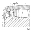
- the Fig. 1 shows a machine axis 12, to which extends symmetrically and concentrically an annular main flow channel 1, which is bounded by a hub assembly 22 and a housing assembly 23. Outside the housing assembly 23, a bypass channel 10 is formed.
- At least one stator 3 is arranged, which has individual stator blades 2. ( Fig. 2 )
- a rotor 5 Downstream of the stator 3 there is provided a rotor 5 having rotor blades 4, which rotates about the machine axis 12, as in the direction of rotation 21 in the Fig. 2 and 6 is shown.
- the Fig. 1 . 3 and 4 show a schematic representation of a plurality of substantially mutually parallel, slot-like, adjacent to the profile trailing edge of the stator (trailing edge) 15 arranged recesses 6, through which a part of the flowing on a suction side 11 of the stator 2 (see Fig. 3 ) is introduced into a flow channel 7, which is formed in the interior of the stator blade 2 and forms a plenum.
- the flow channel 7 extends substantially over the entire radial length of the stator blade 2 and opens into an outflow channel 9, which is formed in the housing assembly 23.
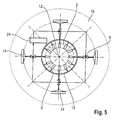
- the respective outflow channel 9, which is assigned to each stator blade 2 opens into an annular channel 13, as well as in Fig. 5 is shown.
- the annular channel 13 thus leads to a pressure uniformization in the circumferential direction.
- shut-off 8 a diffuser 14 which opens into the bypass duct 10.
- the individual shut-off elements (8) can each be actuated as a function of the operating states.
- the slot-like recesses 6 extend transversely to the flow direction, they can be arranged at uniform or varying intervals. It is also possible to provide rows of holes or holes and to vary them in the radial direction. Thus, it is possible to discharge suitable fluid streams from the suction side 11.
- the arrangement of the recesses 6, adjacent to the profile trailing edge of the stator (trailing edge) 15, is advantageous because there is the thickness of the impulse-poor boundary layer, which further downstream of the tail (trailing area 18), is greatest.
- the invention shows in Fig. 7 a preferred embodiment of the invention, wherein guide surfaces 25 on the inner sides 26 of the plenum (flow channel 7) are formed. These serve to guide the flow within the flow channel 7, as indicated by the dashed lines in FIG Fig. 4 is shown (flow 27).
- guide surfaces 25 of the flow within the plenum 7 (flow channel 7) is optimized
- the pressure in the passage 19 between the stator blades 2 is greater than the pressure in the bypass duct 10 and the pressure in a free environment.
- the shut-off elements 8 are opened, a flow is driven by the pressure difference between the flow in the passages 19 and the bypass duct 10 or the free environment. In this case, fluid is sucked out of the passage 19 through the recesses 6, transported through the plenum (flow channel 7) and the Ring channel 13 fed. From there, the fluid passes through the shut-off elements 8 and diffusers 14 in the bypass duct 10 and in the free environment.
- the wake 18 (wake flow) beginning at the profile trailing edges of the stator (trailing edge) 15 becomes weaker in intensity, its Expansion in the circumferential direction becomes narrower.
- the velocity profile in the circumferential direction 20 is equalized and varies weaker.
- the spatial variance of the airfoil decreases in the circumferential direction and, in the case of a relative movement between stator 3 and rotor 5, the temporal variance and amplitude of the pressure field associated therewith, which forms the mechanism of sound generation in the stator / rotor interaction, also decreases.
- the generated noise is thus much lower.
- the tonal interaction noise can thus be reduced within the scope of a noise reduction potential of approximately 5 to 6 dB.
Landscapes
- Engineering & Computer Science (AREA)
- Mechanical Engineering (AREA)
- General Engineering & Computer Science (AREA)
- Chemical & Material Sciences (AREA)
- Combustion & Propulsion (AREA)
- Physics & Mathematics (AREA)
- Fluid Mechanics (AREA)
- Life Sciences & Earth Sciences (AREA)
- Sustainable Development (AREA)
- Geometry (AREA)
- Structures Of Non-Positive Displacement Pumps (AREA)
Description
- Die Erfindung bezieht sich auf eine Turbomaschine mit Geräuschreduzierung gemäß den Merkmalen des Oberbegriffs des Anspruchs 1.
- Im Einzelnen bezieht sich die Erfindung auf eine Turbomaschine mit einem durchströmten ringförmigen Hauptströmungskanal, in welchem zumindest ein mit Statorschaufeln versehener Stator und stromab von diesem ein mit Rotorschaufeln versehener Rotor angeordnet sind. Im Speziellen kann die Erfindung in Form eines Gasturbinentriebwerks oder einer stationären Gasturbine ausgebildet werden.
- Die Erfindung bezieht sich dabei ganz allgemein auf jede Stator-Rotor-Anordnung, welche bei einem Flugzeugtriebwerk oder einer stationären Gasturbineanlage oder eines Wellenleistungstriebwerks vorgesehen sein kann. Die erfindungsgemäße Anordnung kann dabei in den unterschiedlichen Baugruppen zum Einsatz kommen, nämlich beispielsweise bei einem Bläser, bei einem Booster, bei einem Kompressor oder bei einer Turbine.
- Die Erfindung bezieht sich somit ganz allgemein auf Turbomaschinen, bei welchen eine Energieumwandlung stattfindet. Das Arbeitsmedium kann dabei Gas, Dampf oder Flüssigkeit sein.
- Die Erfindung ist somit nicht auf Gasturbinen beschränkt.
- Bei Stator-Rotor-Kombinationen strömt das Arbeitsmedium im Allgemeinen in Richtung einer Rotationsachse (Maschinenachse) oder auch in radialer Richtung oder in eine Kombination aus axialer und radialer Richtung.
- Die
Fig. 2 zeigt in schematischer Weise eine derartige Anordnung in einer Axialschnittebene (siehe auchFig. 1 ). Dabei erfolgt die Strömung von links nach rechts gemäßFig. 2 , so dass die Strömung zunächst Statorschaufeln 2 durchströmt, nachfolgend nach Abströmung von einer Profilhinterkante des Stators (Abströmkante) 15 der jeweiligen Statorschaufel 2 in einen Zwischenraum gelangt und nachfolgend in den Bereich von Rotorschaufeln 4 einströmt. - Das in
Fig. 2 gezeigte ebene Schaufelgitter bewirkt somit, dass in einem durch die Statorschaufeln 2 gebildeten Stator 3 ein Arbeitsmedium 16 in Rotationsrichtung eines durch die Rotorschaufeln 4 gebildeten Rotors 5 umgelenkt wird. In dem Rotor 5 expandiert die Strömung, dabei wird das Arbeitsmedium 16 beschleunigt. Nach dem Impulssatz der Strömungsmechanik ergibt sich aus dem Eintritts- und Austrittsimpuls ein resultierender Impuls, der Reaktionsimpuls. Die daraus resultierende Kraftkomponente in Umfangsrichtung versetzt den Rotor 5 in Rotation. Stromab der Profilhinterkanten des Stators (Abströmkanten) 15 von Stator 3 bzw. Profilhinterkante des Rotors (Abströmkante) 17 von Rotor 5 besitzt die Strömung lokale Gebiete mit geringem Impuls. Diese sogenannten Nachlaufgebiete sind inFig. 2 mit dem Bezugszeichen 18 dargestellt. Die Strömung des Nachlaufes weist eine geringere Strömungsgeschwindigkeit in Richtung der Hauptströmung gegenüber der Strömung in einer Passage 19 zwischen den Statorschaufeln 2 sowie eine Wirbelbildung auf. - Die
Fig. 2 zeigt eine variierende Strömungsgeschwindigkeit infolge der Nachläufe, welche sich periodisch in Umfangsrichtung 20 ergibt. Durch die relative Bewegung zwischen dem Rotor 5 und dem Stator 3 bzw. dem Stator 3 und dem Rotor 5 entstehen somit eine zeitveränderliche Geschwindigkeit und ein zeitveränderlicher Impuls an einem Ort im ruhenden System (Stator) bzw. bewegten System (Rotor). Trifft die vom Stator 3 bzw. Rotor 5 abgehende Strömung auf den stromab liegenden Rotor bzw. Stator, erzeugt die zeitveränderliche, periodische Strömung am Rotor bzw. Stator ein zeitlich periodisch veränderliches Druckfeld. Diese Interaktion der Strömung, insbesondere das Auftreffen des Nachlaufs 18 (Nachlaufströmung) auf die Beschaufelung stromab, ist ein unerwünschter, jedoch sehr effektiver Erzeugungsmechanismus für den tonalen Lärm in einer derartigen Turbomaschine. Häufig ist es die dominierende Lärmquelle oder Geräuschquelle. - Derartige Strömungsverhältnisse und Lärmerzeugungsmechanismen treten auch in einem Triebwerksbläser durch eine Interaktion des Nachlaufs des Rotors mit den Statoren des Nebenstromkanals sowie im Kompressor auf.
- Aus dem Stand der Technik sind sowohl aktive als auch passive Lösungen zur Lärmminderung oder Lärmreduzierung bekannt.
- Bei den passiven Lösungen werden beispielsweise akustische Schallabsorber verschiedener Bauform verwendet, welche die Energie der sich ausbreitenden akustischen Felder reduzieren. Bauartbedingt sind derartige Maßnahmen jedoch nicht immer optimal einsetzbar und auch hinsichtlich ihrer Wirkung nicht völlig zufriedenstellend.
- Bei den aktiven Lösungen sind verstellbare Elemente an den Vorderkanten und/oder Hinterkanten von Profilen bekannt. Derartige Maßnahmen sind technisch schwierig zu realisieren. Weiterhin ist es bekannt, gasförmige oder flüssige Medien aus der Oberfläche von Rotoren bzw. Statoren auszublasen. Eine derartige Lösung zeigt beispielsweise die
US 5 813 625 A . - Das Ausblasen von Fluid in der Nähe der Vorderkante bzw. Hinterkante erweist sich jedoch nicht als effizient.
- Aus der
EP 1 536 146 A2 ist eine Strömungsarbeitsmaschine mit Fluidentnahme vorbekannt. Bei dieser wird Fluid durch die Statorschaufeln abgeleitet. Dieses Fluid wird jedoch entweder zur Umgebung hin abgeleitet oder in den Strömungskanal zurückgeführt. - Eine ähnliche Ausgestaltung zeigt die
EP 1 382 855 A2 . - Die
GB 1 085 227 A - Der Erfindung liegt die Aufgabe zugrunde, eine Gasturbine der eingangs genannten Art zu schaffen, welche bei einfachem Aufbau und einfacher, kostengünstiger Herstellbarkeit die Nachteile des Standes der Technik vermeidet und ein hohes Maß an Geräuschreduzierung ermöglicht.
- Erfindungsgemäß wird die Aufgabe durch die Merkmalskombination des Anspruchs 1 gelöst, die Unteransprüche zeigen weitere vorteilhafte Ausgestaltungen der Erfindung.
- Erfindungsgemäß ist somit vorgesehen, dass die Statorschaufeln jeweils zumindest eine Ausnehmung aufweisen, welche in einen Strömungskanal innerhalb der Statorschaufel mündet, und dass der Strömungskanal über zumindest einen mit einem Absperrelement versehenen Ausströmkanal in einen Nebenstromkanal der Gasturbine mündet.
- Erfindungsgemäß wird somit durch die zumindest eine Ausnehmung Fluid im Bereich der Statorschaufel abgeführt und aus dem ringförmigen Hauptströmungskanal abgeleitet. Durch diese aktive Maßnahme ist es möglich, in Abhängigkeit vom Arbeitspunkt der Turbomaschine (Gasturbine) eine erhebliche Geräuschminimierung zu erzielen.
- Erfindungsgemäß sind die Ausnehmungen in günstiger Ausgestaltung schlitzartig oder als linienartige Reihe von Bohrungen oder Ausnehmungen ausgebildet und befinden sich bevorzugterweise an der Saugseite der Statorschaufel. In besonders günstiger Weiterbildung der Erfindung ist vorgesehen, dass sich die Ausnehmungen im Wesentlichen über die gesamte radiale Länge der Statorschaufel erstrecken. Es ist erfindungsgemäß jedoch auch möglich, die durch die Ausnehmungen geschaffene Ausströmfläche in radialer Richtung zu variieren, so dass sich am radial inneren oder radial äußeren Bereich der Statorschaufel unterschiedliche Ausströmflächen ergeben.
- Erfindungsgemäß kann es weiterhin günstig sein, mehrere Ausnehmungen, Schlitze oder Reihen von Löchern vorzusehen, die in Strömungsrichtung aufeinanderfolgend und somit nebeneinander angeordnet sind. Es ist somit möglich, auf einem angrenzend an die Profilhinterkante des Stators (Abströmkante) 15 der Statorschaufel variablen Bereich Fluid abzuführen.
- Die Abführung des Fluids erfolgt durch den Strömungskanal innerhalb der Statorschaufel, welcher ein Plenum darstellt, in welchem, bedingt durch ein relativ großes Innenvolumen, ein Abbau von Druckspannungen oder Druckunterschieden erfolgen kann. Mittels des Ausströmkanals wird das Fluid in einen Nebenstromkanal abgeführt. Durch den in dem Nebenstromkanal herrschenden niedrigeren Druck ergibt sich eine Saugwirkung.
- Das zumindest eine Absperrelement kann mittels einer geeigneten Steuerung oder Regelung in Abhängigkeit von den Betriebszuständen geöffnet oder geschlossen werden. So ist es beispielsweise möglich, eine Fluggasturbine im Landeanflug erheblich geräuschzureduzieren. Die Erfindung kann somit aktiv in unterschiedlichen Betriebszuständen genutzt werden.
- Erfindungsgemäß ergibt sich eine Reihe erheblicher Vorteile. Zum einen ergibt sich eine effiziente Reduktion des tonalen Rotorlärms (Stator-Rotor-Interaktionslärm). Weiterhin ergeben sich keine oder nur sehr geringe Strömungsverluste. Die erfindungsgemäße Lösung ist robust, wartungsarm, zeichnet sich durch ein geringes zusätzliches Gewicht aus und benötigt, außer dem Absperrelement, keine beweglichen Teile. Somit ergeben sich erhebliche Vorteile hinsichtlich der Produktionskosten. Ein weiterer Vorteil liegt darin, dass keine zusätzliche Energie erforderlich ist, außer zur Betätigung des Absperrelementes. Durch die Aktivier-Möglichkeit der Erfindung in Abhängigkeit vom jeweiligen Betriebszustand der Maschine ergibt sich eine sehr vorteilhafte variable Einsatzmöglichkeit.
- Es versteht sich, dass die Erfindung auch auf einem Rotor anwendbar ist, aus dessen Rotorblättern Fluid abgeführt und durch eine rotierende Nabe in einen Nebenstromkanal oder die Umgebung abgeleitet wird.
- Im Folgenden wird die Erfindung anhand eines Ausführungsbeispiels in Verbindung mit der Zeichnung beschrieben. Dabei zeigt:
- Fig. 1
- eine schematische Teil-Axialschnitt-Ansicht,
- Fig. 2
- eine Schnittansicht längs der Linie A-A von
Fig. 1 in Abwicklung in einer Ebene, - Fig. 3
- eine vergrößerte Schnittansicht durch eine erfindungsgemäße Statorschaufel in Darstellung analog
Fig. 2 , - Fig. 4
- eine Seitenansicht einer erfindungsgemäßen Statorschaufel in Darstellung analog
Fig. 1 , - Fig. 5
- eine vereinfachte Schnittansicht in einer senkrecht zu einer Maschinenachse angeordneten Ebene,
- Fig. 6
- eine Darstellung der erfindungsgemäßen Strömungsverhältnisse in Schnittansicht A-A analog
Fig. 2 , und - Fig. 7
- eine Seitenansicht, analog
Fig. 4 , mit Darstellung von Leitflächen - Die
Fig. 1 zeigt eine Maschinenachse 12, zu welcher sich symmetrisch und konzentrisch ein ringförmiger Hauptströmungskanal 1 erstreckt, welcher durch eine Nabenanordnung 22 und eine Gehäuseanordnung 23 begrenzt wird. Außerhalb der Gehäuseanordnung 23 ist ein Nebenstromkanal 10 ausgebildet. - In dem ringförmigen Hauptströmungskanal 1 ist zumindest ein Stator 3 angeordnet, welcher einzelne Statorschaufeln 2 aufweist. (
Fig. 2 ) - Stromab des Stators 3 ist ein Rotorschaufeln 4 aufweisender Rotor 5 vorgesehen, welcher sich um die Maschinenachse 12 dreht, so wie dies durch die Rotationsrichtung 21 in den
Fig. 2 und6 dargestellt ist. - Die
Fig. 1 ,3 und 4 zeigen in schematischer Darstellung mehrere im wesentlichen parallel zueinander angeordnete, schlitzartige, benachbart zu der Profilhinterkante des Stators (Abströmkante) 15 angeordnete Ausnehmungen 6, durch welche ein Teil der an einer Saugseite 11 der Statorschaufel 2 strömenden Strömung (sieheFig. 3 ) in einen Strömungskanal 7 eingeleitet wird, welcher im Innenraum der Statorschaufel 2 ausgebildet ist und ein Plenum bildet. Der Strömungskanal 7 erstreckt sich im Wesentlichen über die gesamte radiale Länge der Statorschaufel 2 und mündet in einen Ausströmkanal 9, welcher in der Gehäuseanordnung 23 ausgebildet ist. Der jeweilige Ausströmkanal 9, welcher jeder einzelnen Statorschaufel 2 zugeordnet ist, mündet in einen Ringkanal 13, so wie dies auch inFig. 5 dargestellt ist. Der Ringkanal 13 führt somit zu einer Druckvereinheitlichung in Umfangsrichtung. - Die in den Ringkanal 13 eingeführte Strömung wird über zumindest ein Absperrelement 8 einem Diffusor 14 zugeführt, welcher in den Nebenstromkanal 10 mündet. Mittels einer Steuerung sind die einzelnen Absperrelemente (8) (Ventile) jeweils in Abhängigkeit von den Betriebszuständen betätigbar.
- Wie sich aus den Figuren ergibt, verlaufen bei dem gezeigten Ausführungsbeispiel die schlitzartigen Ausnehmungen 6 quer zur Strömungsrichtung, sie können in gleichmäßigen oder variierenden Abständen angeordnet sein. Es ist auch möglich, Reihen von Bohrungen oder Löchern vorzusehen und diese in radialer Richtung zu variieren. Somit ist es möglich, geeignete Fluidströme von der Saugseite 11 abzuführen.
- Die Anordnung der Ausnehmungen 6, angrenzend an die Profilhinterkante des Stators (Abströmkante) 15, ist vorteilhaft, weil dort die Dicke der impulsarmen Grenzschicht, welche weiter stromab den Nachlauf (Nachlaufgebiet 18) ausmacht, am größten ist.
- Die Erfindung zeigt in
Fig. 7 eine bevorzugte Weiterbildung der Erfindung, bei welcher Leitflächen 25 an den Innenseiten 26 des Plenums (Strömungskanal 7) ausgebildet sind. Diese dienen der Strömungsführung innerhalb des Strömungskanals 7, so wie dies durch die gestrichelten Linien inFig. 4 dargestellt ist (Strömungsverlauf 27). Durch die inFig. 7 gezeigten erfindungsgemäßen Leitflächen 25 wird der Strömungsverlauf innerhalb des Plenums 7 (Strömungskanal 7) optimiert - Erfindungsgemäß erfolgt somit eine Absaugung von Fluid aus der Hauptströmung des Arbeitsmediums 16 in der Passage 19 zwischen den Statorschaufeln 2. Wie sich aus den
Fig. 1 und6 ergibt, ist der Druck in der Passage 19 zwischen den Statorschaufeln 2 größer, als der Druck im Nebenstromkanal 10 bzw. der Druck in einer freien Umgebung. Beim Öffnen der Absperrelemente 8 wird durch die Druckdifferenz zwischen der Strömung in den Passagen 19 und dem Nebenstromkanal 10 bzw. der freien Umgebung eine Strömung angetrieben. Dabei wird Fluid aus der Passage 19 durch die Ausnehmungen 6 abgesogen, durch das Plenum (Strömungskanal 7) transportiert und dem Ringkanal 13 zugeleitet. Von dort gelangt das Fluid durch die Absperrelemente 8 und Diffusoren 14 in den Nebenstromkanal 10 bzw. in die freie Umgebung. - Wie in
Fig. 6 gezeigt, ergibt sich hierdurch ein Effekt auf die Strömung in der Passage 19. Durch das Absaugen von Fluid aus der wandnahen Strömung (Strömungsgrenzschicht) wird der an den Profilhinterkanten des Stators (Abströmkanten) 15 beginnende Nachlauf 18 (Nachlaufströmung) in seiner Intensität schwächer, seine Ausdehnung in Umfangsrichtung wird schmaler. Das Geschwindigkeitsprofil in Umfangsrichtung 20 wird egalisiert und variiert schwächer. Gegenüber der Darstellung derFig. 2 (Stand der Technik) ergibt sich ausFig. 6 , dass die räumliche Varianz des Strömungsprofils in Umfangsrichtung sinkt und bei einer relativen Bewegung zwischen Stator 3 und Rotor 5 die zeitliche Varianz und Amplitude des damit verbundenen Druckfeldes, welches den Mechanismus der Schallerzeugung bei der Stator/Rotor-Wechselwirkung bildet, ebenfalls sinkt. Der generierte Lärm ist somit weitaus geringer. Der tonale Interaktionslärm kann damit im Rahmen eines Lärmreduktionspotentials von ca. 5 bis 6 dB reduziert werden. -
- 1
- Ringförmiger Hauptströmungskanal
- 2
- Statorschaufel
- 3
- Stator
- 4
- Rotorschaufel
- 5
- Rotor
- 6
- Ausnehmung
- 7
- Strömungskanal/Plenum
- 8
- Absperrelement
- 9
- Ausströmkanal
- 10
- Nebenstromkanal
- 11
- Saugseite
- 12
- Maschinenachse
- 13
- Ringkanal
- 14
- Diffusor
- 15
- Profilhinterkante des Stators (Abströmkante)
- 16
- Arbeitsmedium
- 17
- Profilhinterkante des Rotors (Abströmkante)
- 18
- Nachtaufgebiet/Nachlauf / Nachlaufströmung
- 19
- Passage
- 20
- Umfangsrichtung
- 21
- Rotationsrichtung des Rotors
- 22
- Nabenanordnung
- 23
- Gehäuseanordnung
- 24
- Steuerung
- 25
- Leitfläche
- 26
- Innenseite
- 27
- Strömungsverlauf
Claims (15)
- Turbomaschine mit einem durchströmten ringförmigen Hauptströmungskanal (1), in welchem zumindest ein mit Statorschaufeln (2) versehener Stator angeordnet ist, und die Statorschaufeln (2) jeweils zumindest eine Ausnehmung (6) aufweise welche in einen Strömungskanal (7) innerhalb der Statorschaufeln (2) mündet, dadurch gekennzeichnet, dass der Strömungskanal (7) in zumindest einen mit einem Absperrelement (8) versehenen Ausströmkanal (9) in einen Nebenstromkanal (10) der Turbomaschine mündet.
- Turbomaschine nach Anspruch 1, dadurch gekennzeichnet, dass der Stator (3) in Form eines Leitrades ausgebildet ist.
- Turbomaschine nach Anspruch 1 oder 2, dadurch gekennzeichnet, dass die Ausnehmung (6) der Statorschaufel (2) schlitzartig ausgebildet ist.
- Turbomaschine nach einem der Ansprüche 1 oder 2, dadurch gekennzeichnet, dass die Ausnehmung (6) der Statorschaufel (2) als linienartige Reihe von Bohrungen ausgebildet ist.
- Turbomaschine nach einem der Ansprüche 1 bis 4, dadurch gekennzeichnet, dass die Ausnehmungen (6) auf der Saugseite (11) der Statorschaufel (2) angeordnet sind.
- Turbomaschine nach einem der Ansprüche 1 bis 5, dadurch gekennzeichnet, dass die Anordnung der Ausnehmungen (6) angrenzend an eine Profilhinterkante des Stators (15) der Statorschaufel (2) angeordnet ist.
- Turbomaschine nach einem der Ansprüche 1 bis 6, dadurch gekennzeichnet, dass sich die Anordnung im Wesentlichen über die gesamte radiale Länge der Statorschaufel (2) erstreckt.
- Turbomaschine nach einem der Ansprüche 1 bis 7, dadurch gekennzeichnet, dass mehrere Ausnehmungen (6) in gleichen oder unterschiedlichen Abständen zueinander angeordnet sind.
- Turbomaschine nach einem der Ansprüche 1 bis 8, dadurch gekennzeichnet, dass der zumindest eine Ausströmkanal mit einem sich in Umfangsrichtung zu einer Maschinenachse (12) erstreckenden Ringkanal (13) verbunden ist, in welchen die Strömungskanäle (7) der Statorschaufeln (2) münden.
- Turbomaschine nach einem der Ansprüche 1 bis 9, dadurch gekennzeichnet, dass der Ausströmkanal (9) über einen Diffusor (14) in den Nebenstromkanal (10) mündet.
- Turbomaschine nach einem der Ansprüche 1 bis 10, dadurch gekennzeichnet, dass die zumindest eine Ausnehmung (6) zur Verringerung der Intensität und/oder der Ausdehnung in Umfangsrichtung einer an der Profilhinterkante (15) der Statorschaufel (2) abströmenden Nachlaufströmung (18) dimensioniert ausgebildet ist.
- Turbomaschine nach einem der Ansprüche 1 bis 11, dadurch gekennzeichnet, dass das Absperrelement (8) zur Öffnung mittels einer Steuerung (24) bei geräuschrelevanten Betriebszuständen, insbesondere im Landeanflug, ausgebildet ist.
- Verfahren zur Geräuschminderung einer Turbomaschine, nach einem der Ansprüche 1 bis 12, bei welchem zur Verringerung der Intensität einer an einer Profilhinterkante (15) einer Statorschaufel (2) abströmenden Nachlaufströmung (18) durch zumindest eine Ausnehmung (6) der Statorschaufel (2) eine Fluidströmung durch die Statorschaufel (2) abgeleitet wird.
- Verfahren nach Anspruch 13, dadurch gekennzeichnet, dass die Fluidströmung in einen Nebenstromkanal der Turbomaschine geleitet wird.
- Verfahren nach einem der Ansprüche 13 oder 14, dadurch gekennzeichnet, dass die Fluidströmung von den Ausnehmungen (6) durch einen Strömungskanal (7) innerhalb der Statorschaufeln (2) und/oder einen mit den Strömungskanälen (7) strömungsverbundenen Ringkanal (13) geleitet wird.
Applications Claiming Priority (2)
| Application Number | Priority Date | Filing Date | Title |
|---|---|---|---|
| DE102010023703A DE102010023703A1 (de) | 2010-06-14 | 2010-06-14 | Turbomaschine mit Geräuschreduzierung |
| PCT/EP2011/002919 WO2011157398A2 (de) | 2010-06-14 | 2011-06-14 | Turbomaschine mit geräuschreduzierung |
Publications (2)
| Publication Number | Publication Date |
|---|---|
| EP2582921A2 EP2582921A2 (de) | 2013-04-24 |
| EP2582921B1 true EP2582921B1 (de) | 2014-05-14 |
Family
ID=44626979
Family Applications (1)
| Application Number | Title | Priority Date | Filing Date |
|---|---|---|---|
| EP11724976.3A Not-in-force EP2582921B1 (de) | 2010-06-14 | 2011-06-14 | Turbomaschine mit geräuschreduzierung |
Country Status (4)
| Country | Link |
|---|---|
| US (1) | US9574452B2 (de) |
| EP (1) | EP2582921B1 (de) |
| DE (1) | DE102010023703A1 (de) |
| WO (1) | WO2011157398A2 (de) |
Families Citing this family (19)
| Publication number | Priority date | Publication date | Assignee | Title |
|---|---|---|---|---|
| US8246292B1 (en) * | 2012-01-31 | 2012-08-21 | United Technologies Corporation | Low noise turbine for geared turbofan engine |
| US20160130949A1 (en) | 2012-01-31 | 2016-05-12 | United Technologies Corporation | Low noise turbine for geared turbofan engine |
| JP5968173B2 (ja) * | 2012-09-14 | 2016-08-10 | 三菱日立パワーシステムズ株式会社 | 蒸気タービン静翼及び蒸気タービン |
| US20160138474A1 (en) | 2012-09-28 | 2016-05-19 | United Technologies Corporation | Low noise compressor rotor for geared turbofan engine |
| US9624834B2 (en) | 2012-09-28 | 2017-04-18 | United Technologies Corporation | Low noise compressor rotor for geared turbofan engine |
| US10605172B2 (en) | 2013-03-14 | 2020-03-31 | United Technologies Corporation | Low noise turbine for geared gas turbine engine |
| US11719161B2 (en) | 2013-03-14 | 2023-08-08 | Raytheon Technologies Corporation | Low noise turbine for geared gas turbine engine |
| ES2925599T3 (es) * | 2013-04-09 | 2022-10-18 | MTU Aero Engines AG | Cascada de álabes para una turbomáquina y método de fabricación asociado |
| US10196982B2 (en) * | 2015-11-04 | 2019-02-05 | General Electric Company | Gas turbine engine having a flow control surface with a cooling conduit |
| US10428660B2 (en) * | 2017-01-31 | 2019-10-01 | United Technologies Corporation | Hybrid airfoil cooling |
| DE102017222210A1 (de) * | 2017-12-07 | 2019-06-13 | MTU Aero Engines AG | Verdichtermodul für eine Strömungsmaschine |
| JP7045851B2 (ja) * | 2017-12-28 | 2022-04-01 | 三菱重工業株式会社 | 燃焼器及びガスタービン |
| US11408349B2 (en) | 2020-08-14 | 2022-08-09 | Raytheon Technologies Corporation | Active flow control transpirational flow acoustically lined guide vane |
| US11512608B2 (en) | 2020-08-14 | 2022-11-29 | Raytheon Technologies Corporation | Passive transpirational flow acoustically lined guide vane |
| WO2022113570A1 (ja) * | 2020-11-25 | 2022-06-02 | 三菱パワー株式会社 | タービン |
| US11555420B1 (en) * | 2021-08-20 | 2023-01-17 | Raytheon Technologies Corporation | Frame connection between fan case and core housing in a gas turbine engine |
| US11674415B2 (en) | 2021-08-20 | 2023-06-13 | Raytheon Technologies Corporation | Front section stiffness ratio |
| US11708772B2 (en) * | 2021-11-12 | 2023-07-25 | Raytheon Technologies Corporation | Triangular-frame connection between fan case and core housing in a gas turbine engine |
| US11686220B2 (en) * | 2021-11-12 | 2023-06-27 | Raytheon Technologies Corporation | H-frame connection between fan case and core housing in a gas turbine engine |
Family Cites Families (11)
| Publication number | Priority date | Publication date | Assignee | Title |
|---|---|---|---|---|
| US2720356A (en) * | 1952-06-12 | 1955-10-11 | John R Erwin | Continuous boundary layer control in compressors |
| DE1456067A1 (de) * | 1962-12-24 | 1970-07-30 | Hermann Papst | Anordnungen zur Grenzschichtbeeinflussung bei Schaufeln von Geblaesen oder Turbinen |
| GB1085227A (en) | 1963-07-26 | 1967-09-27 | Rolls Royce | Improvements in or relating to gas turbine engines |
| FR2734320B1 (fr) * | 1995-05-15 | 1997-07-18 | Aerospatiale | Dispositif pour prelever et refroidir de l'air chaud au niveau d'un moteur d'aeronef |
| US5813625A (en) | 1996-10-09 | 1998-09-29 | Mcdonnell Douglas Helicopter Company | Active blowing system for rotorcraft vortex interaction noise reduction |
| AU2003205939A1 (en) * | 2002-02-19 | 2003-09-09 | Alstom Technology Ltd | Turboblower and method for operating such a turboblower |
| DE10233032A1 (de) | 2002-07-20 | 2004-01-29 | Rolls-Royce Deutschland Ltd & Co Kg | Strömungsarbeitsmaschine mit integriertem Fluidzirkulationssystem |
| GB2407142B (en) * | 2003-10-15 | 2006-03-01 | Rolls Royce Plc | An arrangement for bleeding the boundary layer from an aircraft engine |
| DE10355240A1 (de) | 2003-11-26 | 2005-07-07 | Rolls-Royce Deutschland Ltd & Co Kg | Strömungsarbeitsmaschine mit Fluidentnahme |
| FR2911923B1 (fr) | 2007-01-25 | 2011-07-08 | Snecma | Redresseur acoustique pour carter de soufflante de turboreacteur |
| US7607287B2 (en) * | 2007-05-29 | 2009-10-27 | United Technologies Corporation | Airfoil acoustic impedance control |
-
2010
- 2010-06-14 DE DE102010023703A patent/DE102010023703A1/de not_active Withdrawn
-
2011
- 2011-06-14 EP EP11724976.3A patent/EP2582921B1/de not_active Not-in-force
- 2011-06-14 WO PCT/EP2011/002919 patent/WO2011157398A2/de not_active Ceased
- 2011-06-14 US US13/704,073 patent/US9574452B2/en not_active Expired - Fee Related
Also Published As
| Publication number | Publication date |
|---|---|
| DE102010023703A1 (de) | 2011-12-15 |
| EP2582921A2 (de) | 2013-04-24 |
| US20130195610A1 (en) | 2013-08-01 |
| WO2011157398A3 (de) | 2013-04-04 |
| US9574452B2 (en) | 2017-02-21 |
| WO2011157398A2 (de) | 2011-12-22 |
Similar Documents
| Publication | Publication Date | Title |
|---|---|---|
| EP2582921A2 (de) | Turbomaschine mit geräuschreduzierung | |
| EP1659293B1 (de) | Strömungsmaschine | |
| EP1004748B1 (de) | Laufrad für eine Strömungsmaschine | |
| EP2659093B1 (de) | Strömungsmaschine | |
| EP2179143B1 (de) | Spaltkühlung zwischen brennkammerwand und turbinenwand einer gasturbinenanlage | |
| EP0690206A2 (de) | Diffusor für Turbomaschine | |
| DE1964057A1 (de) | Kompressor | |
| DE10233032A1 (de) | Strömungsarbeitsmaschine mit integriertem Fluidzirkulationssystem | |
| EP2101040A2 (de) | Strömungsarbeitsmaschine mit mehrstromiger Rotoranordnung | |
| EP2617947B1 (de) | Fluggasturbine mit justierbarem Fan | |
| EP2543861B1 (de) | Fluggasturbine mit variabler Nebenstromdüse | |
| EP3064706A1 (de) | Leitschaufelreihe für eine axial durchströmte Strömungsmaschine | |
| DE10357075B4 (de) | Verfahren zur Lärmreduzierung von Turbomaschinen | |
| DE112015005131B4 (de) | Kühlstruktur für Turbine, und Gasturbine | |
| EP3059431A1 (de) | Triebwerksverkleidung einer gasturbine mit schubumkehrvorrichtung und im querschnitt verstellbarer ausströmdüse | |
| EP3561228A1 (de) | Schaufel, schaufelsegment und baugruppe für eine turbomaschine und turbomaschine | |
| EP3124742B1 (de) | Gasturbine | |
| EP3159487B1 (de) | Stator einer turbine einer gasturbine mit verbesserter kühlluftführung | |
| EP3498972B1 (de) | Turbinenmodul für eine strömungsmaschine | |
| DE102016015296A1 (de) | Turbine für einen Abgasturbolader | |
| EP3204614B1 (de) | Vorrichtung zur beeinflussung der strömung in einer turbomaschine | |
| EP3150799A1 (de) | Strömungsleitvorrichtung und turbomaschine mit mindestens einer strömungsleitvorrichtung | |
| EP2944765B1 (de) | Verfahren zum auslegen einer turbine | |
| DE102011119191B4 (de) | Fluidaktuator sowie Gasturbine mit Fluidaktuator | |
| EP2298643B1 (de) | Antriebsrotor mit Luftkanal |
Legal Events
| Date | Code | Title | Description |
|---|---|---|---|
| PUAI | Public reference made under article 153(3) epc to a published international application that has entered the european phase |
Free format text: ORIGINAL CODE: 0009012 |
|
| 17P | Request for examination filed |
Effective date: 20121205 |
|
| AK | Designated contracting states |
Kind code of ref document: A2 Designated state(s): AL AT BE BG CH CY CZ DE DK EE ES FI FR GB GR HR HU IE IS IT LI LT LU LV MC MK MT NL NO PL PT RO RS SE SI SK SM TR |
|
| R17D | Deferred search report published (corrected) |
Effective date: 20130404 |
|
| GRAP | Despatch of communication of intention to grant a patent |
Free format text: ORIGINAL CODE: EPIDOSNIGR1 |
|
| DAX | Request for extension of the european patent (deleted) | ||
| INTG | Intention to grant announced |
Effective date: 20140211 |
|
| GRAS | Grant fee paid |
Free format text: ORIGINAL CODE: EPIDOSNIGR3 |
|
| GRAA | (expected) grant |
Free format text: ORIGINAL CODE: 0009210 |
|
| AK | Designated contracting states |
Kind code of ref document: B1 Designated state(s): AL AT BE BG CH CY CZ DE DK EE ES FI FR GB GR HR HU IE IS IT LI LT LU LV MC MK MT NL NO PL PT RO RS SE SI SK SM TR |
|
| REG | Reference to a national code |
Ref country code: GB Ref legal event code: FG4D Free format text: NOT ENGLISH |
|
| REG | Reference to a national code |
Ref country code: AT Ref legal event code: REF Ref document number: 668456 Country of ref document: AT Kind code of ref document: T Effective date: 20140615 |
|
| REG | Reference to a national code |
Ref country code: IE Ref legal event code: FG4D Free format text: LANGUAGE OF EP DOCUMENT: GERMAN |
|
| REG | Reference to a national code |
Ref country code: DE Ref legal event code: R096 Ref document number: 502011003120 Country of ref document: DE Effective date: 20140626 |
|
| REG | Reference to a national code |
Ref country code: NL Ref legal event code: VDEP Effective date: 20140514 |
|
| REG | Reference to a national code |
Ref country code: LT Ref legal event code: MG4D |
|
| PG25 | Lapsed in a contracting state [announced via postgrant information from national office to epo] |
Ref country code: CY Free format text: LAPSE BECAUSE OF FAILURE TO SUBMIT A TRANSLATION OF THE DESCRIPTION OR TO PAY THE FEE WITHIN THE PRESCRIBED TIME-LIMIT Effective date: 20140514 Ref country code: LT Free format text: LAPSE BECAUSE OF FAILURE TO SUBMIT A TRANSLATION OF THE DESCRIPTION OR TO PAY THE FEE WITHIN THE PRESCRIBED TIME-LIMIT Effective date: 20140514 Ref country code: FI Free format text: LAPSE BECAUSE OF FAILURE TO SUBMIT A TRANSLATION OF THE DESCRIPTION OR TO PAY THE FEE WITHIN THE PRESCRIBED TIME-LIMIT Effective date: 20140514 Ref country code: GR Free format text: LAPSE BECAUSE OF FAILURE TO SUBMIT A TRANSLATION OF THE DESCRIPTION OR TO PAY THE FEE WITHIN THE PRESCRIBED TIME-LIMIT Effective date: 20140815 Ref country code: NO Free format text: LAPSE BECAUSE OF FAILURE TO SUBMIT A TRANSLATION OF THE DESCRIPTION OR TO PAY THE FEE WITHIN THE PRESCRIBED TIME-LIMIT Effective date: 20140814 Ref country code: IS Free format text: LAPSE BECAUSE OF FAILURE TO SUBMIT A TRANSLATION OF THE DESCRIPTION OR TO PAY THE FEE WITHIN THE PRESCRIBED TIME-LIMIT Effective date: 20140914 |
|
| PG25 | Lapsed in a contracting state [announced via postgrant information from national office to epo] |
Ref country code: SE Free format text: LAPSE BECAUSE OF FAILURE TO SUBMIT A TRANSLATION OF THE DESCRIPTION OR TO PAY THE FEE WITHIN THE PRESCRIBED TIME-LIMIT Effective date: 20140514 Ref country code: RS Free format text: LAPSE BECAUSE OF FAILURE TO SUBMIT A TRANSLATION OF THE DESCRIPTION OR TO PAY THE FEE WITHIN THE PRESCRIBED TIME-LIMIT Effective date: 20140514 Ref country code: LV Free format text: LAPSE BECAUSE OF FAILURE TO SUBMIT A TRANSLATION OF THE DESCRIPTION OR TO PAY THE FEE WITHIN THE PRESCRIBED TIME-LIMIT Effective date: 20140514 Ref country code: ES Free format text: LAPSE BECAUSE OF FAILURE TO SUBMIT A TRANSLATION OF THE DESCRIPTION OR TO PAY THE FEE WITHIN THE PRESCRIBED TIME-LIMIT Effective date: 20140514 Ref country code: PL Free format text: LAPSE BECAUSE OF FAILURE TO SUBMIT A TRANSLATION OF THE DESCRIPTION OR TO PAY THE FEE WITHIN THE PRESCRIBED TIME-LIMIT Effective date: 20140514 Ref country code: HR Free format text: LAPSE BECAUSE OF FAILURE TO SUBMIT A TRANSLATION OF THE DESCRIPTION OR TO PAY THE FEE WITHIN THE PRESCRIBED TIME-LIMIT Effective date: 20140514 |
|
| PG25 | Lapsed in a contracting state [announced via postgrant information from national office to epo] |
Ref country code: PT Free format text: LAPSE BECAUSE OF FAILURE TO SUBMIT A TRANSLATION OF THE DESCRIPTION OR TO PAY THE FEE WITHIN THE PRESCRIBED TIME-LIMIT Effective date: 20140915 |
|
| PG25 | Lapsed in a contracting state [announced via postgrant information from national office to epo] |
Ref country code: RO Free format text: LAPSE BECAUSE OF FAILURE TO SUBMIT A TRANSLATION OF THE DESCRIPTION OR TO PAY THE FEE WITHIN THE PRESCRIBED TIME-LIMIT Effective date: 20140514 Ref country code: SK Free format text: LAPSE BECAUSE OF FAILURE TO SUBMIT A TRANSLATION OF THE DESCRIPTION OR TO PAY THE FEE WITHIN THE PRESCRIBED TIME-LIMIT Effective date: 20140514 Ref country code: CZ Free format text: LAPSE BECAUSE OF FAILURE TO SUBMIT A TRANSLATION OF THE DESCRIPTION OR TO PAY THE FEE WITHIN THE PRESCRIBED TIME-LIMIT Effective date: 20140514 Ref country code: DK Free format text: LAPSE BECAUSE OF FAILURE TO SUBMIT A TRANSLATION OF THE DESCRIPTION OR TO PAY THE FEE WITHIN THE PRESCRIBED TIME-LIMIT Effective date: 20140514 Ref country code: EE Free format text: LAPSE BECAUSE OF FAILURE TO SUBMIT A TRANSLATION OF THE DESCRIPTION OR TO PAY THE FEE WITHIN THE PRESCRIBED TIME-LIMIT Effective date: 20140514 |
|
| REG | Reference to a national code |
Ref country code: CH Ref legal event code: PL |
|
| REG | Reference to a national code |
Ref country code: DE Ref legal event code: R097 Ref document number: 502011003120 Country of ref document: DE |
|
| PG25 | Lapsed in a contracting state [announced via postgrant information from national office to epo] |
Ref country code: NL Free format text: LAPSE BECAUSE OF FAILURE TO SUBMIT A TRANSLATION OF THE DESCRIPTION OR TO PAY THE FEE WITHIN THE PRESCRIBED TIME-LIMIT Effective date: 20140514 |
|
| PLBE | No opposition filed within time limit |
Free format text: ORIGINAL CODE: 0009261 |
|
| STAA | Information on the status of an ep patent application or granted ep patent |
Free format text: STATUS: NO OPPOSITION FILED WITHIN TIME LIMIT |
|
| REG | Reference to a national code |
Ref country code: IE Ref legal event code: MM4A |
|
| 26N | No opposition filed |
Effective date: 20150217 |
|
| PG25 | Lapsed in a contracting state [announced via postgrant information from national office to epo] |
Ref country code: CH Free format text: LAPSE BECAUSE OF NON-PAYMENT OF DUE FEES Effective date: 20140630 Ref country code: IT Free format text: LAPSE BECAUSE OF FAILURE TO SUBMIT A TRANSLATION OF THE DESCRIPTION OR TO PAY THE FEE WITHIN THE PRESCRIBED TIME-LIMIT Effective date: 20140514 Ref country code: IE Free format text: LAPSE BECAUSE OF NON-PAYMENT OF DUE FEES Effective date: 20140614 Ref country code: LI Free format text: LAPSE BECAUSE OF NON-PAYMENT OF DUE FEES Effective date: 20140630 |
|
| REG | Reference to a national code |
Ref country code: DE Ref legal event code: R097 Ref document number: 502011003120 Country of ref document: DE Effective date: 20150217 |
|
| PG25 | Lapsed in a contracting state [announced via postgrant information from national office to epo] |
Ref country code: SI Free format text: LAPSE BECAUSE OF FAILURE TO SUBMIT A TRANSLATION OF THE DESCRIPTION OR TO PAY THE FEE WITHIN THE PRESCRIBED TIME-LIMIT Effective date: 20140514 |
|
| PG25 | Lapsed in a contracting state [announced via postgrant information from national office to epo] |
Ref country code: MT Free format text: LAPSE BECAUSE OF FAILURE TO SUBMIT A TRANSLATION OF THE DESCRIPTION OR TO PAY THE FEE WITHIN THE PRESCRIBED TIME-LIMIT Effective date: 20140514 |
|
| PG25 | Lapsed in a contracting state [announced via postgrant information from national office to epo] |
Ref country code: MC Free format text: LAPSE BECAUSE OF FAILURE TO SUBMIT A TRANSLATION OF THE DESCRIPTION OR TO PAY THE FEE WITHIN THE PRESCRIBED TIME-LIMIT Effective date: 20140514 Ref country code: SM Free format text: LAPSE BECAUSE OF FAILURE TO SUBMIT A TRANSLATION OF THE DESCRIPTION OR TO PAY THE FEE WITHIN THE PRESCRIBED TIME-LIMIT Effective date: 20140514 |
|
| REG | Reference to a national code |
Ref country code: FR Ref legal event code: PLFP Year of fee payment: 6 |
|
| PG25 | Lapsed in a contracting state [announced via postgrant information from national office to epo] |
Ref country code: BG Free format text: LAPSE BECAUSE OF FAILURE TO SUBMIT A TRANSLATION OF THE DESCRIPTION OR TO PAY THE FEE WITHIN THE PRESCRIBED TIME-LIMIT Effective date: 20140514 |
|
| PG25 | Lapsed in a contracting state [announced via postgrant information from national office to epo] |
Ref country code: HU Free format text: LAPSE BECAUSE OF FAILURE TO SUBMIT A TRANSLATION OF THE DESCRIPTION OR TO PAY THE FEE WITHIN THE PRESCRIBED TIME-LIMIT; INVALID AB INITIO Effective date: 20110614 Ref country code: LU Free format text: LAPSE BECAUSE OF NON-PAYMENT OF DUE FEES Effective date: 20140614 Ref country code: BE Free format text: LAPSE BECAUSE OF FAILURE TO SUBMIT A TRANSLATION OF THE DESCRIPTION OR TO PAY THE FEE WITHIN THE PRESCRIBED TIME-LIMIT Effective date: 20140630 Ref country code: TR Free format text: LAPSE BECAUSE OF FAILURE TO SUBMIT A TRANSLATION OF THE DESCRIPTION OR TO PAY THE FEE WITHIN THE PRESCRIBED TIME-LIMIT Effective date: 20140514 |
|
| REG | Reference to a national code |
Ref country code: FR Ref legal event code: PLFP Year of fee payment: 7 |
|
| REG | Reference to a national code |
Ref country code: AT Ref legal event code: MM01 Ref document number: 668456 Country of ref document: AT Kind code of ref document: T Effective date: 20160614 |
|
| PG25 | Lapsed in a contracting state [announced via postgrant information from national office to epo] |
Ref country code: AT Free format text: LAPSE BECAUSE OF NON-PAYMENT OF DUE FEES Effective date: 20160614 |
|
| REG | Reference to a national code |
Ref country code: FR Ref legal event code: PLFP Year of fee payment: 8 |
|
| PG25 | Lapsed in a contracting state [announced via postgrant information from national office to epo] |
Ref country code: MK Free format text: LAPSE BECAUSE OF FAILURE TO SUBMIT A TRANSLATION OF THE DESCRIPTION OR TO PAY THE FEE WITHIN THE PRESCRIBED TIME-LIMIT Effective date: 20140514 |
|
| PG25 | Lapsed in a contracting state [announced via postgrant information from national office to epo] |
Ref country code: AL Free format text: LAPSE BECAUSE OF FAILURE TO SUBMIT A TRANSLATION OF THE DESCRIPTION OR TO PAY THE FEE WITHIN THE PRESCRIBED TIME-LIMIT Effective date: 20140514 |
|
| PGFP | Annual fee paid to national office [announced via postgrant information from national office to epo] |
Ref country code: FR Payment date: 20190625 Year of fee payment: 9 |
|
| PGFP | Annual fee paid to national office [announced via postgrant information from national office to epo] |
Ref country code: GB Payment date: 20190627 Year of fee payment: 9 Ref country code: DE Payment date: 20190627 Year of fee payment: 9 |
|
| REG | Reference to a national code |
Ref country code: DE Ref legal event code: R082 Ref document number: 502011003120 Country of ref document: DE |
|
| REG | Reference to a national code |
Ref country code: DE Ref legal event code: R119 Ref document number: 502011003120 Country of ref document: DE |
|
| GBPC | Gb: european patent ceased through non-payment of renewal fee |
Effective date: 20200614 |
|
| PG25 | Lapsed in a contracting state [announced via postgrant information from national office to epo] |
Ref country code: FR Free format text: LAPSE BECAUSE OF NON-PAYMENT OF DUE FEES Effective date: 20200630 Ref country code: GB Free format text: LAPSE BECAUSE OF NON-PAYMENT OF DUE FEES Effective date: 20200614 |
|
| PG25 | Lapsed in a contracting state [announced via postgrant information from national office to epo] |
Ref country code: DE Free format text: LAPSE BECAUSE OF NON-PAYMENT OF DUE FEES Effective date: 20210101 |