EP2582414B1 - Rotor pour pompe à sang muni de paliers de butée hydrodynamiques à chanfrein - Google Patents
Rotor pour pompe à sang muni de paliers de butée hydrodynamiques à chanfrein Download PDFInfo
- Publication number
- EP2582414B1 EP2582414B1 EP11796539.2A EP11796539A EP2582414B1 EP 2582414 B1 EP2582414 B1 EP 2582414B1 EP 11796539 A EP11796539 A EP 11796539A EP 2582414 B1 EP2582414 B1 EP 2582414B1
- Authority
- EP
- European Patent Office
- Prior art keywords
- rotor
- axis
- chamfer
- pump
- bore
- Prior art date
- Legal status (The legal status is an assumption and is not a legal conclusion. Google has not performed a legal analysis and makes no representation as to the accuracy of the status listed.)
- Active
Links
- 239000008280 blood Substances 0.000 title claims description 31
- 210000004369 blood Anatomy 0.000 title claims description 31
- 238000011144 upstream manufacturing Methods 0.000 claims description 31
- 230000005291 magnetic effect Effects 0.000 claims description 24
- 230000002093 peripheral effect Effects 0.000 description 9
- 239000012530 fluid Substances 0.000 description 6
- 239000000463 material Substances 0.000 description 5
- 238000004891 communication Methods 0.000 description 3
- 230000000694 effects Effects 0.000 description 3
- 210000005240 left ventricle Anatomy 0.000 description 3
- 230000000747 cardiac effect Effects 0.000 description 2
- 230000007423 decrease Effects 0.000 description 2
- 239000003302 ferromagnetic material Substances 0.000 description 2
- 208000019622 heart disease Diseases 0.000 description 2
- 208000014674 injury Diseases 0.000 description 2
- 238000005086 pumping Methods 0.000 description 2
- 230000003068 static effect Effects 0.000 description 2
- 230000008733 trauma Effects 0.000 description 2
- 230000002861 ventricular Effects 0.000 description 2
- 229910000531 Co alloy Inorganic materials 0.000 description 1
- 241000282412 Homo Species 0.000 description 1
- 229910001030 Iron–nickel alloy Inorganic materials 0.000 description 1
- 241000124008 Mammalia Species 0.000 description 1
- 241001465754 Metazoa Species 0.000 description 1
- 229910001260 Pt alloy Inorganic materials 0.000 description 1
- 208000007536 Thrombosis Diseases 0.000 description 1
- 230000001154 acute effect Effects 0.000 description 1
- 210000000709 aorta Anatomy 0.000 description 1
- 230000003190 augmentative effect Effects 0.000 description 1
- 230000017531 blood circulation Effects 0.000 description 1
- 230000036772 blood pressure Effects 0.000 description 1
- 230000002612 cardiopulmonary effect Effects 0.000 description 1
- 239000000919 ceramic Substances 0.000 description 1
- 239000011248 coating agent Substances 0.000 description 1
- 238000000576 coating method Methods 0.000 description 1
- 239000010941 cobalt Substances 0.000 description 1
- GUTLYIVDDKVIGB-UHFFFAOYSA-N cobalt atom Chemical compound [Co] GUTLYIVDDKVIGB-UHFFFAOYSA-N 0.000 description 1
- 230000000295 complement effect Effects 0.000 description 1
- 238000005094 computer simulation Methods 0.000 description 1
- 230000005347 demagnetization Effects 0.000 description 1
- 230000002706 hydrostatic effect Effects 0.000 description 1
- 238000002513 implantation Methods 0.000 description 1
- 230000003993 interaction Effects 0.000 description 1
- 229910052751 metal Inorganic materials 0.000 description 1
- 239000002184 metal Substances 0.000 description 1
- 238000012986 modification Methods 0.000 description 1
- 230000004048 modification Effects 0.000 description 1
- 230000001453 nonthrombogenic effect Effects 0.000 description 1
- 238000011084 recovery Methods 0.000 description 1
- 210000005241 right ventricle Anatomy 0.000 description 1
- 238000004088 simulation Methods 0.000 description 1
- 238000009987 spinning Methods 0.000 description 1
- 238000001356 surgical procedure Methods 0.000 description 1
- 238000002054 transplantation Methods 0.000 description 1
- 230000002792 vascular Effects 0.000 description 1
Images


Classifications
-
- F—MECHANICAL ENGINEERING; LIGHTING; HEATING; WEAPONS; BLASTING
- F04—POSITIVE - DISPLACEMENT MACHINES FOR LIQUIDS; PUMPS FOR LIQUIDS OR ELASTIC FLUIDS
- F04D—NON-POSITIVE-DISPLACEMENT PUMPS
- F04D29/00—Details, component parts, or accessories
- F04D29/04—Shafts or bearings, or assemblies thereof
- F04D29/041—Axial thrust balancing
- F04D29/0413—Axial thrust balancing hydrostatic; hydrodynamic thrust bearings
-
- A—HUMAN NECESSITIES
- A61—MEDICAL OR VETERINARY SCIENCE; HYGIENE
- A61M—DEVICES FOR INTRODUCING MEDIA INTO, OR ONTO, THE BODY; DEVICES FOR TRANSDUCING BODY MEDIA OR FOR TAKING MEDIA FROM THE BODY; DEVICES FOR PRODUCING OR ENDING SLEEP OR STUPOR
- A61M60/00—Blood pumps; Devices for mechanical circulatory actuation; Balloon pumps for circulatory assistance
- A61M60/10—Location thereof with respect to the patient's body
- A61M60/122—Implantable pumps or pumping devices, i.e. the blood being pumped inside the patient's body
- A61M60/126—Implantable pumps or pumping devices, i.e. the blood being pumped inside the patient's body implantable via, into, inside, in line, branching on, or around a blood vessel
- A61M60/135—Implantable pumps or pumping devices, i.e. the blood being pumped inside the patient's body implantable via, into, inside, in line, branching on, or around a blood vessel inside a blood vessel, e.g. using grafting
-
- A—HUMAN NECESSITIES
- A61—MEDICAL OR VETERINARY SCIENCE; HYGIENE
- A61M—DEVICES FOR INTRODUCING MEDIA INTO, OR ONTO, THE BODY; DEVICES FOR TRANSDUCING BODY MEDIA OR FOR TAKING MEDIA FROM THE BODY; DEVICES FOR PRODUCING OR ENDING SLEEP OR STUPOR
- A61M60/00—Blood pumps; Devices for mechanical circulatory actuation; Balloon pumps for circulatory assistance
- A61M60/20—Type thereof
- A61M60/205—Non-positive displacement blood pumps
- A61M60/216—Non-positive displacement blood pumps including a rotating member acting on the blood, e.g. impeller
- A61M60/237—Non-positive displacement blood pumps including a rotating member acting on the blood, e.g. impeller the blood flow through the rotating member having mainly axial components, e.g. axial flow pumps
-
- A—HUMAN NECESSITIES
- A61—MEDICAL OR VETERINARY SCIENCE; HYGIENE
- A61M—DEVICES FOR INTRODUCING MEDIA INTO, OR ONTO, THE BODY; DEVICES FOR TRANSDUCING BODY MEDIA OR FOR TAKING MEDIA FROM THE BODY; DEVICES FOR PRODUCING OR ENDING SLEEP OR STUPOR
- A61M60/00—Blood pumps; Devices for mechanical circulatory actuation; Balloon pumps for circulatory assistance
- A61M60/40—Details relating to driving
- A61M60/403—Details relating to driving for non-positive displacement blood pumps
- A61M60/422—Details relating to driving for non-positive displacement blood pumps the force acting on the blood contacting member being electromagnetic, e.g. using canned motor pumps
-
- A—HUMAN NECESSITIES
- A61—MEDICAL OR VETERINARY SCIENCE; HYGIENE
- A61M—DEVICES FOR INTRODUCING MEDIA INTO, OR ONTO, THE BODY; DEVICES FOR TRANSDUCING BODY MEDIA OR FOR TAKING MEDIA FROM THE BODY; DEVICES FOR PRODUCING OR ENDING SLEEP OR STUPOR
- A61M60/00—Blood pumps; Devices for mechanical circulatory actuation; Balloon pumps for circulatory assistance
- A61M60/80—Constructional details other than related to driving
- A61M60/802—Constructional details other than related to driving of non-positive displacement blood pumps
- A61M60/818—Bearings
- A61M60/824—Hydrodynamic or fluid film bearings
-
- F—MECHANICAL ENGINEERING; LIGHTING; HEATING; WEAPONS; BLASTING
- F04—POSITIVE - DISPLACEMENT MACHINES FOR LIQUIDS; PUMPS FOR LIQUIDS OR ELASTIC FLUIDS
- F04D—NON-POSITIVE-DISPLACEMENT PUMPS
- F04D29/00—Details, component parts, or accessories
- F04D29/18—Rotors
- F04D29/181—Axial flow rotors
-
- A—HUMAN NECESSITIES
- A61—MEDICAL OR VETERINARY SCIENCE; HYGIENE
- A61M—DEVICES FOR INTRODUCING MEDIA INTO, OR ONTO, THE BODY; DEVICES FOR TRANSDUCING BODY MEDIA OR FOR TAKING MEDIA FROM THE BODY; DEVICES FOR PRODUCING OR ENDING SLEEP OR STUPOR
- A61M60/00—Blood pumps; Devices for mechanical circulatory actuation; Balloon pumps for circulatory assistance
- A61M60/10—Location thereof with respect to the patient's body
- A61M60/122—Implantable pumps or pumping devices, i.e. the blood being pumped inside the patient's body
- A61M60/126—Implantable pumps or pumping devices, i.e. the blood being pumped inside the patient's body implantable via, into, inside, in line, branching on, or around a blood vessel
- A61M60/148—Implantable pumps or pumping devices, i.e. the blood being pumped inside the patient's body implantable via, into, inside, in line, branching on, or around a blood vessel in line with a blood vessel using resection or like techniques, e.g. permanent endovascular heart assist devices
-
- Y—GENERAL TAGGING OF NEW TECHNOLOGICAL DEVELOPMENTS; GENERAL TAGGING OF CROSS-SECTIONAL TECHNOLOGIES SPANNING OVER SEVERAL SECTIONS OF THE IPC; TECHNICAL SUBJECTS COVERED BY FORMER USPC CROSS-REFERENCE ART COLLECTIONS [XRACs] AND DIGESTS
- Y10—TECHNICAL SUBJECTS COVERED BY FORMER USPC
- Y10S—TECHNICAL SUBJECTS COVERED BY FORMER USPC CROSS-REFERENCE ART COLLECTIONS [XRACs] AND DIGESTS
- Y10S415/00—Rotary kinetic fluid motors or pumps
- Y10S415/90—Rotary blood pump
Definitions
- Heart pumps are typically used in the later stages of heart disease or after trauma to the heart, when the heart itself is too weak or otherwise incapable of creating sufficient blood pressure and blood circulation to satisfy body function.
- Heart pumps are already in use for the purpose of augmenting or replacing the blood pumping action of damaged or diseased hearts.
- Heart pumps are commonly used in three situations: (1)for acute support during cardio-pulmonary operations; (2) for short-term support while awaiting recovery of the heart from surgery; or (3) as a bridge to keep a patient alive while awaiting heart transplantation.
- the pumps may be designed to provide at least one of right or left ventricular assist, although left ventricular assist is the most common application in that it is far more common for the left ventricle to become diseased or damaged than it is for the right ventricle.
- Intravascular pumps comprise miniaturized pumps capable of being percutaneously or surgically introduced into the vascular system of a patient, typically to provide left or right heart support, or even total heart support.
- Various types of intravascular pumps include radial flow centrifugal pumps and axial flow pumps.
- US 2006/0245959 A1 discloses a blood pump comprising a pump housing; a plurality of rotors positioned in said housing, each rotor comprising an impeller having a hydrodynamic surface for pumping blood; a motor including a plurality of magnetic poles carried by each impeller, and motor stators, each including electrically conductive coils, located adjacent to or within said housing; at least one of said rotors being adapted to rotate clockwise and at least one of said rotors being adapted to rotate counterclockwise.
- One form of axial flow heart pump is disclosed in co-pending, commonly assigned U.S. Patent Application No 12/322,746 ("the '746 Application").
- An axial flow pump uses magnetic or electromagnetic forces, for example, to power a magnetic rotor placed within a flow path of blood moving into or out of the heart.
- An electromagnet, or stator is positioned around the outside of a tubular casing containing the flow path, whereas the rotor is disposed inside the casing. The axis of the rotor is coincident with the axis of the casing.
- the rotor is magnetic.
- the stator typically is a set of electrically conductive coils.
- the rotor is energized by a power source with alternating currents through the coils to create a rotating magnetic field. That is, the field is directed transverse to the axis of the tubular casing, and the direction of the field rotates about the axis of the casing. As the field rotates, the rotor spins about its axis.
- the rotor is configured with vanes which impel the blood in a downstream direction along the axis as the rotor turns in a forward direction of rotation.
- the circumferential surface of the rotor includes hydrodynamic bearing surfaces.
- the power source may be implanted somewhere within the body of the patient or may be external to the patient, as is known in the art.
- Axial flow cardiac pumps are efficient, compact and reliable.
- the forces associated with axial flow cardiac pumps can present problems.
- the rotor impels the blood in the downstream direction, the blood applies thrust forces to the rotor. These thrust forces urge the rotor in the upstream direction.
- the static pressure of the blood downstream from the rotor is greater than the static pressure of the blood upstream from the rotor.
- the pressure differential also urges the rotor in the upstream direction along the axis. Under certain flow conditions, especially at lower flow volumes and/or higher rotational speeds, the axial stiffness of the stator may not be capable of counteracting the axial forces on the rotor.
- the rotor may even contact a mechanical stop, such as a narrowed portion of the casing, which is provided as a backup or emergency restraint. Such contact can cause wear on the rotor and casing, which in turn can shorten the life of the pump and cause other undesirable effects.
- a mechanical stop such as a narrowed portion of the casing
- a rotor for a blood circulating pump according to independent claim 1.
- a rotor has a magnetic, biocompatible body having an upstream end, a downstream end and an axis extending between the ends.
- the body includes a plurality of vanes defining a plurality of channels therebetween, and is constructed and arranged to impel blood downstream upon rotation of said rotor in a forward circumferential direction.
- the vanes have hydrodynamic thrust bearing surfaces, each such thrust bearing surface being constructed and arranged to apply a hydrodynamic force to the rotor upon rotation of said rotor in the forward circumferential direction, with a component of this force directed in the downstream direction.
- a further aspect of the invention provides an implantable blood circulating pump according to claim 11.
- a pump includes a casing having an interior bore having an axis, an upstream end, a downstream end, and a stop surface bounding the bore.
- the said stop surface is substantially in the form of at least a portion of a surface of revolution about the bore axis.
- the stop surface has a diameter increasing progressively in a downstream direction along said bore axis.
- the pump according to this aspect of the invention also includes a rotor according to claim 1 disposed within the bore, the rotor comprising a magnetic, biocompatible body including a plurality of vanes defining a plurality of channels therebetween.
- the rotor is constructed and arranged to impel blood downstream upon rotation of the rotor within said bore in a forward circumferential direction about the axis.
- the vanes have hydrodynamic thrust bearing surfaces, each such thrust bearing surface being constructed and arranged to apply a hydrodynamic force to said rotor with a component of said force in the downstream direction upon rotation of said rotor in the forward circumferential direction.
- the pump according to this aspect of the invention also includes a stator disposed in proximity to the casing outside said bore, said stator including one or more electromagnetic coils for applying a magnetic field to said rotor so as to rotate said rotor about said axis.
- downstream forces applied to the rotor through the hydrodynamic thrust bearing surfaces helps to offset the forces tending to move the rotor upstream during operation.
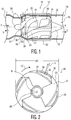
- a blood circulating pump 10 includes a rotor having body 20.
- the body 20 is magnetic and biocompatible, and further includes an upstream end 23, a downstream end 24 and an axis R extending between the ends.
- the body 20 further includes a plurality of vanes 25 defining a plurality of channels 21 therebetween.
- the rotor body 20 is constructed and arranged to impel blood downstream, in the direction of fluid flow F, upon rotation of the rotor about axis R in a forward circumferential direction FC ( FIG. 2 ).
- the forward circumferential direction FC is the clockwise direction as seen in FIG. 2 , looking downstream towards the upstream end of the rotor.
- Each vane 25 includes at least one hydrodynamic thrust bearing surface 35. As further explained below, each thrust bearing surface 35 is constructed and arranged to apply a hydrodynamic force V ( FIG. 1 ) to the rotor with a component of the force in the downstream direction D upon rotation of the rotor in the forward circumferential direction FC. Each vane 25 also has additional radial bearing surfaces 22 along the length of body 20. The radial bearing surfaces are arranged to apply hydrodynamic forces directed generally radially inwardly, toward axis R, upon rotation of the rotor in the forward circumferential direction.
- Each thrust bearing surface 35 has a normal vector X.
- the normal vector of a surface is the vector directed out of the surface and perpendicular to the surface. Where the surface is non-planar, the normal vector of the surface as referred to herein should be understood as the integral of the normal vector over the entire extent of the surface.
- the normal vector X of each thrust bearing surface includes non-zero components in the radially outward direction, in the upstream direction, and in the circumferentially forward direction. As best seen in FIG. 1 , vector X projects in the upstream direction U and projects radially outward, away from the axis of rotation R. As best seen in FIG. 2 , each vector X also slopes and slightly in the circumferentially forward direction.
- the rotor body 20 includes a principal surface of revolution about the axis R, generally defined as the peripheral surfaces of vanes 25, that is substantially cylindrical in shape.
- the substantially cylindrical principal surface of revolution generally has an outside diameter OD ( FIG. 2 ), which is preferably about 4 to about 12 mm in the case of a blood pump intended for intravascular implantation in an adult human, and more preferably about 9 to 11 mm.
- Vanes 25 define chamfer surfaces 30 at the upstream ends of the vanes.
- the chamfer surfaces 30 slope radially outwardly in the downstream direction, so that the chamfer surfaces are in the form of portions of a conical surface of revolution about the axis having increasing diameter in the downstream direction. As illustrated in FIGS.
- the downstream diameter of the chamfer surfaces 30 is substantially equal to the first diameter of the vanes and the cylindrical surface of revolution of body 20.
- Thrust bearing surfaces 35 are provided as portions of the chamfer surfaces 30. Thrust bearing surfaces 35 are recessed relative to surrounding portions of the chamfer surfaces 30 such that each thrust bearing surface 35 defines a pocket in the chamfer surfaces 30.
- Each pocket, defining thrust bearing surface 35 includes a leading portion 36 and a trailing portion 37, relative to the forward circumferential direction FC.
- the pocket has a progressively increasing depth such that the deepest portion of the pocket is at leading portion 36. Stated another way, each thrust bearing surface slopes progressively outward, toward the surrounding chamfer surface 30, in the direction from the leading portion to the trailing portion.
- leading portion 36 is open to adjacent channel 21.
- the chamfer surfaces 30 define a chamfer angle A such that the chamfer surfaces are positioned at an angle relative to axis R and relative the cylindrical surface of revolution of the rotor body 20.
- the chamfer angle is in the range of 20 degrees to 45 degrees.
- the chamfer angle A of the chamfer surfaces 30 may be about 30 degrees.
- the chamfer surfaces 30 have a chamfer length L measured in the axial directions which may be in the range of about .06 inches (1.5 mm) to about .1 inches (2.5 mm). In one example, the chamfer length L is about .08 inches (2 mm).
- the rotor body 20 may further include and projection members 28 and 29 extending upstream and downstream from the vanes.
- the particular example of the rotor shown in FIGS. 1-3 includes four vanes 25 defining four channels 21, each vane having two radial bearings 22 on the peripheral surfaces of the vanes defining the cylindrical surface of revolution of body 20. While the configuration of the vanes, channels and radial thrust bearings may be generally in accordance with the aforementioned '746 Application, their configuration is, within the scope the present invention, solely defined by the appended claims.
- each channel 21 slopes in the circumferentially forward direction FC toward the upstream end of the body, so that as the body rotates in the circumferentially forward direction, the surfaces of the body defining the channels will impel blood in the downstream direction D.
- Each radial bearing 22 is formed as a recessed pocket in the peripheral surface of the vane, and each such pocket has its maximum depth at the leading edge of the pocket, i.e. , the edge of the pocket which lies at the circumferentially forward side. The depth of each pocket 22 decreases progressively toward the trailing end of the pocket.
- the radial bearing pockets 22 are open to channels 21 at the leading edges of the pockets. Any number of vanes and radial bearings is contemplated.
- Rotor body 20 is positioned within a hollow casing 50.
- the hollow casing 50 defines an interior bore 55 therethrough, within which the rotor body 20 is positioned.
- Casing 50 also includes an upstream end and a downstream end, corresponding to the direction of fluid flow F, and corresponding to the upstream and downstream ends of the rotor.
- the interior bore has a central axis R coincident with the central axis of the rotor, an inlet 57 at its upstream end and an outlet 59 at its downstream end.
- Casing 50 further includes a mechanical stop surface 56 positioned upstream of vanes and chamfer surfaces of rotor body 20. The stop surface 56 is intended to prohibit excessive upstream motion of the rotor body 20 out of its ordinary position.
- the stop surface 56 is positioned adjacent to a portion of the rotor body 20 and may be shaped similarly to such portion of body 20.
- the stop surface 56 is substantially in the form of a surface of revolution about the central axis R, such surface facing inwardly toward the central axis.
- the stop surface 56 has a diameter increasing progressively in the downstream direction.
- the stop surface 56 is substantially conical, and lies at an angle A to the central axis which is substantially equal to the angle A of the chamfer surfaces 30.
- the stop surface may have a length in the axial direction approximately equal to the length L of the chamfer surfaces 30.
- the smaller (minor) inside diameter of the stop surface should be less than the outside diameter OD defined by the vanes.
- the main portion of the bore 55, downstream from stop surface 56 desirably has an inside diameter just slightly larger than the outside diameter OD defined by the vanes on the rotor.
- the casing may include additional features such as a downstream stop (not shown) to prevent movement of the rotor out of the casing through the outlet 59 while the pump is inactive.
- a set of stationary vanes sometimes referred to as a "diffuser" (not shown) may be positioned downstream from the rotor.
- the vanes of the diffuser may be arranged to reduce rotation of fluid around the axis R.
- a stator 52 is disposed in proximity to casing 50 and outside of the interior bore 55 and preferably surrounding at least a portion of the rotor body 20.
- the stator 52 may include one or more electromagnetic coils, most commonly a plurality of coils such as three coils disposed at equal 120 degree intervals about the central axis R, as discussed above and as is known in the art.
- a power source (not shown) creates alternating currents which pass through the coils, to create a magnetic field in a direction transverse to axis R and rotating axis R. This field is applied to the rotor so as to rotate the rotor body 20 about axis R.
- the magnetic field of the stator also tends to hold the rotor in position along the axis, in alignment with the stator. As discussed above, this effect is referred to as the axial magnetic stiffness of the stator.
- Casing 50 may be made of any non-ferromagnetic material capable of handling the rotor 20 operation, which substantially resists thrombosis, and which is biocompatible. Desirably, the casing material should be resistant to mechanical wear.
- the material of casing 50 may be a ceramic.
- Rotor body 20 includes a magnetically hard ferromagnetic material, i.e. , a material which forms a strong permanent magnet and which is resistant to demagnetization.
- the material of the rotor body also should be biocompatible and substantially non-thrombogenic.
- the rotor body may be formed as a unitary mass of an alloy of platinum and cobalt.
- the rotor body may be formed from a magnetic metal such as an iron-nickel alloy with an exterior coating of another material to increase the body's biocompatibility.
- the rotor is magnetized with a magnetic field transverse to the axis R, so as to provide magnetic poles at the peripheral surfaces of the vanes.
- the pump is implanted in a mammalian subject such as a human subject, with the inlet 57 and outlet 59 of the bore in communication with the circulatory system of the subject.
- a mammalian subject such as a human subject
- the inlet 57 may be in communication with the interior of the left ventricle
- the outlet 59 may be in communication with the aorta.
- the stator is actuated by the power source to provide a rotating magnetic field and thus spin the rotor 20 about axis R in the forward circumferential direction FC.
- the spinning rotor draws the blood into the channels 21 and impels the blood downstream, in the fluid flow direction F.
- the radial bearings 22 hold the rotor centered within the bore 55 of the housing and out of contact with the wall of the bore.
- the radial bearings 22 operate as hydrodynamic bearings. A small portion of the blood passing through the pump enters the pockets of the radial bearings, and encounters the sloping pocket surfaces. This interaction generates forces on the rotor directed radially inwardly, toward the axis.
- a small portion of the blood flowing within bore 55 passes between the chamfer surfaces 30 of the rotor and the stop surface 56 of the casing.
- This blood enters into the pockets defined by thrust bearing surfaces 35.
- the thrust bearings also operate as hydrodynamic bearings.
- the thrust bearing surfaces As the rotor turns, the blood contained in the pockets applies forces to the thrust bearing surfaces. These forces are directed approximately normal to the bearing surfaces. Thus, the forces are directed along vector V, approximately opposite to the normal vector X of each thrust bearing surface.
- the forces on the thrust bearing surfaces thus have components directed radially inwardly, toward axis R, and also have components directed in the downstream direction D.
- the rotor is subjected to thrust forces and pressure forces directed upstream.
- the downstream component of the forces on the thrust bearing surfaces helps to counteract these forces.
- the downstream component of the forces on the thrust bearing together with the axial magnetic stiffness of the stator, prevents the rotor from moving upstream and keeps the rotor out of contact with the stop surface 56.
- the downstream force component generated by the thrust bearings varies directly with the sine of the chamfer angle A and varies directly with the chamfer length L.
- the maximum downstream force component would be obtained at a chamfer angle of 90 degrees.
- such a chamfer angle would mean that the stop surface constitutes an abrupt step in diameter of the bore 55.
- chamfer angles of about 20-45 degrees or less facilitate fluid flow through the bore and still provide adequate downstream force components.
- the radially-directed force components from the thrust bearings mean that the thrust bearings act as additional radial bearings at the upstream end of the rotor. The thrust bearings thus help to stabilize the rotor and maintain it centered in the bore of the housing.
- the forces applied to the thrust bearings are directly related to the area of the thrust bearings. Surprisingly, despite the relatively small area available for the thrust bearings on the chamfer surfaces of the vanes, the thrust bearings provide enough force to aid in keeping the rotor out of contact with the stop surface. The forces applied to the thrust bearings also vary directly with the rotational speed of the rotor. This means that the forces applied by the thrust bearings will be greatest when they are most needed.
- the chamfer surfaces 30, and thrust bearing surfaces 35 may decrease or eliminate the risk of the rotor body 20 contacting the stop surface 56. This may be particularly useful when operating the pump 10 at higher speeds and/or capacity.
- the chamfer surfaces 30 and thrust bearing surfaces 35 may also allow the pump 10 to be operated at higher rotational speeds than a comparable pump without thrust bearings, to provide a greater pressure differential, greater flow rate or both.
- FIGS. 4 and 5 display the results of hydrodynamic simulations run on the pump 10 with thrust bearings as shown in FIGS. 1-3 (labeled "New Chamfer") versus an existing pump having a rotor of comparable configuration (labeled "Orig Rotor).
- the "Axial Load” (expressed in pounds force) represents the summation of all hydrodynamic and hydrostatic forces acting on the rotor.
- the axial load does not include magnetic forces associated with the axial magnetic stiffness of the stator.
- the axial load is the load which must be resisted by the axial magnetic stiffness of the stator to hold the rotor in place.
- Data is presented for combinations of rotors and casings with different radial gaps (labeled “Rad Gap”).
- the "radial gap” is one-half of the difference between the outside diameter of the rotor and the inside diameter of the bore in the casing.
- a positive axial load represents a load which tends to push the rotor upstream
- a negative axial load represents a net load in the downstream direction.
- the graphs show that the absolute value of axial loading on the rotor is significantly less for the pump with the thrust bearing, under all operating conditions studied.
- a pump according to a further embodiment of the invention includes a rotor body 120 ( FIG. 6 ) positioned within a casing 150.
- the vanes of the rotor flare radially outwardly and define chamfer surfaces 130 near the downstream end 124 of rotor body 20 rather than at the upstream end 123.
- the body 120 includes a substantially cylindrical body, but has a portion having a first diameter and a portion having a second diameter. The two portions are separated by the chamfer surfaces 130.
- Chamfer surfaces 130 are provided with thrust bearing surfaces 135, similar to thrust bearing surfaces of the embodiment discussed above.
- Casing 150 includes stop surface 156, which in this example is positioned downstream of the stator 152.
- the stop surface has a form of at least a portion of a surface of revolution about axis R'. This surface has a diameter which increases progressively in the downstream direction along the bore axis R'.
- Pump 110 operates in a similar fashion as the pump 10 discussed above with reference to FIGS. 1-3 .
- rotor body 120 is prevented from migrating upstream by combined action of the magnet stiffness of stator 152 and the force generated by thrust surfaces 135.
- FIG. 7 illustrates yet another embodiment of a blood circulating pump 210.
- the vanes of the rotor progressively increase in diameter along the length of the body.
- the main portion of rotor body 220 has a tapered peripheral surface 221 in the form of a surface of revolution about axis R" having progressively increasing diameter in the downstream direction.
- the peripheral surface 221 of the rotor main portion is a cone having a generatrix disposed at an angle A" to axis R". This peripheral surface is provided with bearing surfaces 235.
- the casing 250 includes a bore with an interior surface 256 which also has a diameter which increases progressively in the downstream direction along the axis R".
- the inwardly facing surface 256 is complementary to the outwardly facing peripheral surface 221 of the rotor.
- surface 256 may be a conical surface having a generatrix disposed at approximately the same angle A" to axis R".
- the stator 252 surrounds at least a portion of the interior surface 256 and tapered peripheral surface 221 of the rotor.
- each bearing surface 235 has a normal vector X" with a positive, non-zero component in the upstream direction U" and also in the radially outward direction, away from axis R".
- the normal vector X" also has a component in the circumferentially forward direction.
- each bearing surface 235 Upon rotation of rotor 220 about axis R" in the forward direction, each bearing surface 235 will be subjected to forces directed along vector V", with both downstream and radially inward components.
- bearing surfaces 235 act as radial bearings to keep the rotor centered in the bore of the housing, and also act as thrust bearing surfaces to provide downstream forces on the rotor.
- the bearing surfaces 235 may be larger than the bearing surfaces 35 ( FIGS. 1-3 ), the angle A" may be relatively small as, for example, a few degrees while still providing sufficient downstream force component. However, the angle A" according to the present invention is in the range of 20 degrees to less than 45 degrees.
- the exemplary devices and uses herein focus on the use of the pump as a heart pump for the transfer of blood therethrough, for use in humans or other mammals in the event of heart disease or severe trauma. However, it is envisioned that other similar uses may be available for use on other animals or for other anatomical systems requiring assisted fluid flow.
Landscapes
- Health & Medical Sciences (AREA)
- Engineering & Computer Science (AREA)
- Heart & Thoracic Surgery (AREA)
- Mechanical Engineering (AREA)
- Anesthesiology (AREA)
- Animal Behavior & Ethology (AREA)
- Veterinary Medicine (AREA)
- Public Health (AREA)
- General Health & Medical Sciences (AREA)
- Cardiology (AREA)
- Life Sciences & Earth Sciences (AREA)
- Biomedical Technology (AREA)
- Hematology (AREA)
- General Engineering & Computer Science (AREA)
- Physics & Mathematics (AREA)
- Fluid Mechanics (AREA)
- Vascular Medicine (AREA)
- Transplantation (AREA)
- Structures Of Non-Positive Displacement Pumps (AREA)
- External Artificial Organs (AREA)
Claims (13)
- Rotor pour une pompe de circulation sanguine destinée à la circulation du sang, le rotor comprenant un corps magnétique biocompatible (20) ayant une extrémité amont (23), une extrémité aval (24) et un axe (R) s'étendant entre les extrémités sur lequel le rotor tourne circonférentiellement, le corps comportant une pluralité d'aubes (25) définissant une pluralité de canaux (21) entre elles, le rotor étant construit et agencé pour propulser le sang en aval lors de la rotation du rotor autour de l'axe dans une direction circonférentielle avant (FC),
les aubes définissant des surfaces de chanfrein (30), les surfaces de chanfrein ayant la forme de parties d'une surface conique de révolution autour de l'axe ayant un diamètre croissant dans la direction aval (D), les surfaces de chanfrein comportant un angle de chanfrein de telle sorte que les surfaces de chanfrein sont positionnées à un angle par rapport à l'axe, caractérisé en ce que :l'angle de chanfrein est dans la plage de 20 degrés à moins de 45 degrés, les aubes ont des surfaces de palier de butée hydrodynamiques (35) prévues sous forme de parties des surfaces de chanfrein et évidées par rapport aux parties environnantes des surfaces de chanfrein de telle sorte que chaque surface de palier de butée définit une poche dans les surfaces de chanfrein, chacune desdites poches dans la surface de chanfrein ayant une profondeur progressivement croissante dans la direction circonférentielle avant, etchacune de ces surfaces de palier de butée est construite et agencée pour appliquer une force hydrodynamique (V) au rotor avec une composante de la force dans une direction en aval le long de l'axe lors de la rotation du rotor dans la direction circonférentielle avant. - Rotor selon la revendication 1, chacune desdites surfaces de palier de butée hydrodynamiques ayant un vecteur normal avec des composantes non-nulles dans les directions amont et circonférentielle avant.
- Rotor selon la revendication 2, le vecteur normal de chacune desdites surfaces de palier de butée hydrodynamiques ayant également une composante non nulle dans une direction radiale vers l'extérieur, à l'opposé de l'axe.
- Rotor selon la revendication 1, l'angle de chanfrein étant d'environ 30 degrés.
- Rotor selon la revendication 1, les surfaces de chanfrein comportant une longueur de chanfrein (L) mesurée dans la direction axiale, la longueur de chanfrein étant dans la plage d'environ 0,15 cm à environ 0,25 cm, de préférence d'environ 0,2 cm.
- Rotor selon la revendication 1, chacune desdites poches ayant une extrémité circonférentielle avant ouverte vers l'un desdits canaux.
- Rotor selon la revendication 6, la poche définissant une hauteur d'espace, mesurée à l'extrémité avant ouverte de la poche, d'environ 0,0025 cm à environ 0,005 cm, de préférence d'environ 0,0038 cm.
- Pompe comprenant un rotor selon la revendication 1, et un carter (50) ayant un alésage intérieur (55) ayant un axe (R), une extrémité amont, une extrémité aval et une surface d'arrêt (56) délimitant l'alésage, la surface de butée ayant sensiblement la forme d'au moins une partie de la surface de révolution et ayant un diamètre augmentant progressivement vers l'aval le long de l'axe de l'alésage, le rotor étant disposé à l'intérieur du carter avec l'extrémité amont du rotor disposée adjacent à la surface d'arrêt.
- Pompe selon la revendication 8, la surface d'arrêt ayant une forme sensiblement inverse aux surfaces de chanfrein.
- Pompe selon la revendication 8, comprenant en outre un stator (52) disposé à proximité du carter à l'extérieur de l'alésage, le stator comportant une ou plusieurs bobines électromagnétiques pour appliquer un champ magnétique au rotor de manière à faire tourner le rotor autour de l'axe.
- Pompe de circulation sanguine implantable, la pompe comprenant le rotor selon la revendication 1, la pompe comprenant en outre :un carter ayant un alésage intérieur présentant un axe, une extrémité amont, une extrémité aval et une surface d'arrêt délimitant l'alésage, la surface d'arrêt ayant sensiblement la forme d'au moins une partie d'une surface de révolution autour de l'axe d'alésage ayant un diamètre augmentant progressivement dans une direction aval le long de l'axe de l'alésage ;un stator disposé à proximité du carter à l'extérieur de l'alésage, le stator comportant une ou plusieurs bobines électromagnétiques pour appliquer un champ magnétique au rotor de manière à faire tourner le rotor autour de l'axe.
- Pompe selon la revendication 11, chacune desdites surfaces de palier de butée hydrodynamiques ayant un vecteur normal avec des composantes non nulles dans les directions amont et circonférentiellement avant, de préférence le vecteur normal de chacune desdites surfaces de palier de butée hydrodynamiques ayant également un composant non-nul dans une direction radiale vers l'extérieur, s'écartant de l'axe.
- Pompe selon la revendication 11, la surface d'arrêt ayant une forme sensiblement inverse aux surfaces de chanfrein.
Applications Claiming Priority (2)
| Application Number | Priority Date | Filing Date | Title |
|---|---|---|---|
| US39797210P | 2010-06-18 | 2010-06-18 | |
| PCT/US2011/040938 WO2011160056A1 (fr) | 2010-06-18 | 2011-06-17 | Palier de butée hydrodynamique à chanfrein |
Publications (3)
| Publication Number | Publication Date |
|---|---|
| EP2582414A1 EP2582414A1 (fr) | 2013-04-24 |
| EP2582414A4 EP2582414A4 (fr) | 2018-02-28 |
| EP2582414B1 true EP2582414B1 (fr) | 2021-08-04 |
Family
ID=45328850
Family Applications (1)
| Application Number | Title | Priority Date | Filing Date |
|---|---|---|---|
| EP11796539.2A Active EP2582414B1 (fr) | 2010-06-18 | 2011-06-17 | Rotor pour pompe à sang muni de paliers de butée hydrodynamiques à chanfrein |
Country Status (3)
| Country | Link |
|---|---|
| US (1) | US8894387B2 (fr) |
| EP (1) | EP2582414B1 (fr) |
| WO (1) | WO2011160056A1 (fr) |
Families Citing this family (25)
| Publication number | Priority date | Publication date | Assignee | Title |
|---|---|---|---|---|
| US9492600B2 (en) | 2011-05-13 | 2016-11-15 | Heartware, Inc. | Intravascular blood pump and method of implantation |
| AU2013259287B2 (en) | 2012-05-11 | 2017-02-02 | Heartware, Inc. | Silver motor stator for implantable blood pump |
| US10111994B2 (en) | 2013-05-14 | 2018-10-30 | Heartware, Inc. | Blood pump with separate mixed-flow and axial-flow impeller stages and multi-stage stators |
| AU2014306563A1 (en) | 2013-08-14 | 2016-02-18 | Heartware, Inc. | Impeller for axial flow pump |
| JP2016044673A (ja) * | 2014-08-22 | 2016-04-04 | 日本電産株式会社 | 動圧軸受ポンプ |
| JP2016044674A (ja) * | 2014-08-22 | 2016-04-04 | 日本電産株式会社 | 動圧軸受ポンプ |
| CN104162191B (zh) * | 2014-09-05 | 2016-08-24 | 长治市久安人工心脏科技开发有限公司 | 一种液磁悬浮轴流式心脏辅助血泵 |
| WO2016187057A1 (fr) | 2015-05-15 | 2016-11-24 | Thoratec Corporation | Amélioration d'une pompe à sang à écoulement axial |
| WO2017173217A1 (fr) * | 2016-04-01 | 2017-10-05 | Heartware, Inc. | Pompe à sang à écoulement axial dotée d'un rotor décalé radialement |
| CN109641092B (zh) * | 2016-09-06 | 2021-03-12 | 心脏器械股份有限公司 | 用于心室内vad的集成传感器 |
| WO2018213666A1 (fr) * | 2017-05-19 | 2018-11-22 | Heartware, Inc. | Aimant de tige centrale |
| JP7414529B2 (ja) | 2017-06-07 | 2024-01-16 | シファメド・ホールディングス・エルエルシー | 血管内流体移動デバイス、システム、および使用方法 |
| JP7319266B2 (ja) | 2017-11-13 | 2023-08-01 | シファメド・ホールディングス・エルエルシー | 血管内流体移動デバイス、システム、および使用方法 |
| DE102018201030A1 (de) | 2018-01-24 | 2019-07-25 | Kardion Gmbh | Magnetkuppelelement mit magnetischer Lagerungsfunktion |
| CN117959583A (zh) | 2018-02-01 | 2024-05-03 | 施菲姆德控股有限责任公司 | 血管内血泵以及使用和制造方法 |
| US11331467B2 (en) * | 2018-04-24 | 2022-05-17 | Tc1 Llc | Percutaneous heart pump transitionable between separated and operational configurations |
| DE102018211327A1 (de) | 2018-07-10 | 2020-01-16 | Kardion Gmbh | Laufrad für ein implantierbares, vaskuläres Unterstützungssystem |
| CN109821084B (zh) * | 2019-03-22 | 2019-10-29 | 河海大学 | 一种基于流道渐变的可植入无轴心脏泵 |
| EP3996797A4 (fr) | 2019-07-12 | 2023-08-02 | Shifamed Holdings, LLC | Pompes à sang intravasculaires et méthode d'utilisation et procédé de fabrication |
| WO2021016372A1 (fr) | 2019-07-22 | 2021-01-28 | Shifamed Holdings, Llc | Pompes à sang intravasculaires à entretoises et procédés d'utilisation et de fabrication |
| US11724089B2 (en) | 2019-09-25 | 2023-08-15 | Shifamed Holdings, Llc | Intravascular blood pump systems and methods of use and control thereof |
| DE102020102474A1 (de) | 2020-01-31 | 2021-08-05 | Kardion Gmbh | Pumpe zum Fördern eines Fluids und Verfahren zum Herstellen einer Pumpe |
| US20210378678A1 (en) * | 2020-06-08 | 2021-12-09 | White Swell Medical Ltd | Non-thrombogenic devices for treating edema |
| CN113153804B (zh) * | 2021-04-27 | 2022-12-06 | 丰凯利医疗器械(上海)有限公司 | 一种泵血叶轮及心室辅助装置 |
| CN113546297B (zh) * | 2021-07-14 | 2022-06-17 | 清华大学 | 植入式微型磁悬浮轴流血泵 |
Family Cites Families (12)
| Publication number | Priority date | Publication date | Assignee | Title |
|---|---|---|---|---|
| US5211546A (en) * | 1990-05-29 | 1993-05-18 | Nu-Tech Industries, Inc. | Axial flow blood pump with hydrodynamically suspended rotor |
| EP0599138A3 (fr) | 1992-11-27 | 1994-12-07 | Urawa Kohgyo Co Ltd | Pompe de sang pour faire circuler le sang. |
| AUPO902797A0 (en) * | 1997-09-05 | 1997-10-02 | Cortronix Pty Ltd | A rotary blood pump with hydrodynamically suspended impeller |
| DE20004136U1 (de) * | 2000-03-04 | 2000-12-14 | Krankenhausbetr Sgesellschaft | Blutpumpe |
| WO2005032620A1 (fr) * | 2003-10-09 | 2005-04-14 | Ventracor Limited | Turbine |
| US7972122B2 (en) * | 2005-04-29 | 2011-07-05 | Heartware, Inc. | Multiple rotor, wide blade, axial flow pump |
| US8419609B2 (en) * | 2005-10-05 | 2013-04-16 | Heartware Inc. | Impeller for a rotary ventricular assist device |
| CA2636418A1 (fr) * | 2006-01-13 | 2007-07-26 | Heartware, Inc. | Pompe sanguine rotative |
| EP2131888B1 (fr) | 2007-02-26 | 2017-04-05 | HeartWare, Inc. | Dispositif d'assistance ventriculaire intervasculaire |
| JP5442598B2 (ja) * | 2007-04-30 | 2014-03-12 | ハートウェア、インコーポレイテッド | 遠心回転血液ポンプ |
| WO2009099644A1 (fr) | 2008-02-08 | 2009-08-13 | Heartware, Inc. | Dispositif d'assistance ventriculaire pour une mise en place intraventriculaire |
| US8551163B2 (en) * | 2010-10-07 | 2013-10-08 | Everheart Systems Inc. | Cardiac support systems and methods for chronic use |
-
2011
- 2011-06-17 EP EP11796539.2A patent/EP2582414B1/fr active Active
- 2011-06-17 WO PCT/US2011/040938 patent/WO2011160056A1/fr active Application Filing
- 2011-06-17 US US13/163,253 patent/US8894387B2/en active Active
Non-Patent Citations (1)
| Title |
|---|
| None * |
Also Published As
| Publication number | Publication date |
|---|---|
| EP2582414A1 (fr) | 2013-04-24 |
| WO2011160056A1 (fr) | 2011-12-22 |
| US8894387B2 (en) | 2014-11-25 |
| US20110311383A1 (en) | 2011-12-22 |
| EP2582414A4 (fr) | 2018-02-28 |
Similar Documents
| Publication | Publication Date | Title |
|---|---|---|
| EP2582414B1 (fr) | Rotor pour pompe à sang muni de paliers de butée hydrodynamiques à chanfrein | |
| US11883641B2 (en) | Axial flow blood pump | |
| US7798952B2 (en) | Axial flow blood pump | |
| US9943630B2 (en) | Impeller for axial flow pump | |
| EP3436106B1 (fr) | Pompe à sang à écoulement axial dotée d'un rotor décalé radialement | |
| US7467929B2 (en) | Device for axially conveying fluids | |
| EP2145108B1 (fr) | Pompe à sang rotative centrifuge | |
| US10926012B2 (en) | Blood pump, preferably for assisting a heart | |
| US20140309481A1 (en) | Rotary pump with levitated impeller having thrust bearing for improved startup | |
| CA2636418A1 (fr) | Pompe sanguine rotative | |
| JP2006525460A (ja) | 流体ポンプ | |
| US11318295B2 (en) | HVAD rinse via a non-uniform thrust bearing gap | |
| AU2004277286B2 (en) | Impeller |
Legal Events
| Date | Code | Title | Description |
|---|---|---|---|
| PUAI | Public reference made under article 153(3) epc to a published international application that has entered the european phase |
Free format text: ORIGINAL CODE: 0009012 |
|
| 17P | Request for examination filed |
Effective date: 20130107 |
|
| AK | Designated contracting states |
Kind code of ref document: A1 Designated state(s): AL AT BE BG CH CY CZ DE DK EE ES FI FR GB GR HR HU IE IS IT LI LT LU LV MC MK MT NL NO PL PT RO RS SE SI SK SM TR |
|
| DAX | Request for extension of the european patent (deleted) | ||
| RA4 | Supplementary search report drawn up and despatched (corrected) |
Effective date: 20180131 |
|
| RIC1 | Information provided on ipc code assigned before grant |
Ipc: A61M 1/12 20060101AFI20180125BHEP Ipc: F04D 3/00 20060101ALI20180125BHEP Ipc: F04D 29/041 20060101ALI20180125BHEP Ipc: F04D 29/18 20060101ALI20180125BHEP |
|
| STAA | Information on the status of an ep patent application or granted ep patent |
Free format text: STATUS: EXAMINATION IS IN PROGRESS |
|
| 17Q | First examination report despatched |
Effective date: 20190603 |
|
| STAA | Information on the status of an ep patent application or granted ep patent |
Free format text: STATUS: EXAMINATION IS IN PROGRESS |
|
| REG | Reference to a national code |
Ref country code: DE Ref legal event code: R079 Ref document number: 602011071499 Country of ref document: DE Free format text: PREVIOUS MAIN CLASS: A61M0001120000 Ipc: F04D0029041000 |
|
| GRAP | Despatch of communication of intention to grant a patent |
Free format text: ORIGINAL CODE: EPIDOSNIGR1 |
|
| STAA | Information on the status of an ep patent application or granted ep patent |
Free format text: STATUS: GRANT OF PATENT IS INTENDED |
|
| RIC1 | Information provided on ipc code assigned before grant |
Ipc: A61M 60/824 20210101ALN20210304BHEP Ipc: F04D 29/18 20060101ALI20210304BHEP Ipc: A61M 60/148 20210101ALN20210304BHEP Ipc: A61M 60/422 20210101ALN20210304BHEP Ipc: F04D 29/041 20060101AFI20210304BHEP Ipc: A61M 60/205 20210101ALN20210304BHEP |
|
| RIC1 | Information provided on ipc code assigned before grant |
Ipc: F04D 29/041 20060101AFI20210309BHEP Ipc: F04D 29/18 20060101ALI20210309BHEP Ipc: A61M 60/148 20210101ALN20210309BHEP Ipc: A61M 60/205 20210101ALN20210309BHEP Ipc: A61M 60/422 20210101ALN20210309BHEP Ipc: A61M 60/824 20210101ALN20210309BHEP |
|
| INTG | Intention to grant announced |
Effective date: 20210326 |
|
| GRAS | Grant fee paid |
Free format text: ORIGINAL CODE: EPIDOSNIGR3 |
|
| GRAA | (expected) grant |
Free format text: ORIGINAL CODE: 0009210 |
|
| STAA | Information on the status of an ep patent application or granted ep patent |
Free format text: STATUS: THE PATENT HAS BEEN GRANTED |
|
| AK | Designated contracting states |
Kind code of ref document: B1 Designated state(s): AL AT BE BG CH CY CZ DE DK EE ES FI FR GB GR HR HU IE IS IT LI LT LU LV MC MK MT NL NO PL PT RO RS SE SI SK SM TR |
|
| REG | Reference to a national code |
Ref country code: GB Ref legal event code: FG4D |
|
| REG | Reference to a national code |
Ref country code: AT Ref legal event code: REF Ref document number: 1417248 Country of ref document: AT Kind code of ref document: T Effective date: 20210815 |
|
| REG | Reference to a national code |
Ref country code: CH Ref legal event code: EP |
|
| REG | Reference to a national code |
Ref country code: DE Ref legal event code: R096 Ref document number: 602011071499 Country of ref document: DE |
|
| REG | Reference to a national code |
Ref country code: IE Ref legal event code: FG4D |
|
| REG | Reference to a national code |
Ref country code: LT Ref legal event code: MG9D |
|
| REG | Reference to a national code |
Ref country code: NL Ref legal event code: MP Effective date: 20210804 |
|
| REG | Reference to a national code |
Ref country code: AT Ref legal event code: MK05 Ref document number: 1417248 Country of ref document: AT Kind code of ref document: T Effective date: 20210804 |
|
| PG25 | Lapsed in a contracting state [announced via postgrant information from national office to epo] |
Ref country code: HR Free format text: LAPSE BECAUSE OF FAILURE TO SUBMIT A TRANSLATION OF THE DESCRIPTION OR TO PAY THE FEE WITHIN THE PRESCRIBED TIME-LIMIT Effective date: 20210804 Ref country code: SE Free format text: LAPSE BECAUSE OF FAILURE TO SUBMIT A TRANSLATION OF THE DESCRIPTION OR TO PAY THE FEE WITHIN THE PRESCRIBED TIME-LIMIT Effective date: 20210804 Ref country code: AT Free format text: LAPSE BECAUSE OF FAILURE TO SUBMIT A TRANSLATION OF THE DESCRIPTION OR TO PAY THE FEE WITHIN THE PRESCRIBED TIME-LIMIT Effective date: 20210804 Ref country code: BG Free format text: LAPSE BECAUSE OF FAILURE TO SUBMIT A TRANSLATION OF THE DESCRIPTION OR TO PAY THE FEE WITHIN THE PRESCRIBED TIME-LIMIT Effective date: 20211104 Ref country code: LT Free format text: LAPSE BECAUSE OF FAILURE TO SUBMIT A TRANSLATION OF THE DESCRIPTION OR TO PAY THE FEE WITHIN THE PRESCRIBED TIME-LIMIT Effective date: 20210804 Ref country code: NO Free format text: LAPSE BECAUSE OF FAILURE TO SUBMIT A TRANSLATION OF THE DESCRIPTION OR TO PAY THE FEE WITHIN THE PRESCRIBED TIME-LIMIT Effective date: 20211104 Ref country code: RS Free format text: LAPSE BECAUSE OF FAILURE TO SUBMIT A TRANSLATION OF THE DESCRIPTION OR TO PAY THE FEE WITHIN THE PRESCRIBED TIME-LIMIT Effective date: 20210804 Ref country code: PT Free format text: LAPSE BECAUSE OF FAILURE TO SUBMIT A TRANSLATION OF THE DESCRIPTION OR TO PAY THE FEE WITHIN THE PRESCRIBED TIME-LIMIT Effective date: 20211206 Ref country code: FI Free format text: LAPSE BECAUSE OF FAILURE TO SUBMIT A TRANSLATION OF THE DESCRIPTION OR TO PAY THE FEE WITHIN THE PRESCRIBED TIME-LIMIT Effective date: 20210804 Ref country code: ES Free format text: LAPSE BECAUSE OF FAILURE TO SUBMIT A TRANSLATION OF THE DESCRIPTION OR TO PAY THE FEE WITHIN THE PRESCRIBED TIME-LIMIT Effective date: 20210804 |
|
| PG25 | Lapsed in a contracting state [announced via postgrant information from national office to epo] |
Ref country code: PL Free format text: LAPSE BECAUSE OF FAILURE TO SUBMIT A TRANSLATION OF THE DESCRIPTION OR TO PAY THE FEE WITHIN THE PRESCRIBED TIME-LIMIT Effective date: 20210804 Ref country code: LV Free format text: LAPSE BECAUSE OF FAILURE TO SUBMIT A TRANSLATION OF THE DESCRIPTION OR TO PAY THE FEE WITHIN THE PRESCRIBED TIME-LIMIT Effective date: 20210804 Ref country code: GR Free format text: LAPSE BECAUSE OF FAILURE TO SUBMIT A TRANSLATION OF THE DESCRIPTION OR TO PAY THE FEE WITHIN THE PRESCRIBED TIME-LIMIT Effective date: 20211105 |
|
| PG25 | Lapsed in a contracting state [announced via postgrant information from national office to epo] |
Ref country code: NL Free format text: LAPSE BECAUSE OF FAILURE TO SUBMIT A TRANSLATION OF THE DESCRIPTION OR TO PAY THE FEE WITHIN THE PRESCRIBED TIME-LIMIT Effective date: 20210804 |
|
| PG25 | Lapsed in a contracting state [announced via postgrant information from national office to epo] |
Ref country code: DK Free format text: LAPSE BECAUSE OF FAILURE TO SUBMIT A TRANSLATION OF THE DESCRIPTION OR TO PAY THE FEE WITHIN THE PRESCRIBED TIME-LIMIT Effective date: 20210804 |
|
| REG | Reference to a national code |
Ref country code: DE Ref legal event code: R097 Ref document number: 602011071499 Country of ref document: DE |
|
| PG25 | Lapsed in a contracting state [announced via postgrant information from national office to epo] |
Ref country code: SM Free format text: LAPSE BECAUSE OF FAILURE TO SUBMIT A TRANSLATION OF THE DESCRIPTION OR TO PAY THE FEE WITHIN THE PRESCRIBED TIME-LIMIT Effective date: 20210804 Ref country code: SK Free format text: LAPSE BECAUSE OF FAILURE TO SUBMIT A TRANSLATION OF THE DESCRIPTION OR TO PAY THE FEE WITHIN THE PRESCRIBED TIME-LIMIT Effective date: 20210804 Ref country code: RO Free format text: LAPSE BECAUSE OF FAILURE TO SUBMIT A TRANSLATION OF THE DESCRIPTION OR TO PAY THE FEE WITHIN THE PRESCRIBED TIME-LIMIT Effective date: 20210804 Ref country code: EE Free format text: LAPSE BECAUSE OF FAILURE TO SUBMIT A TRANSLATION OF THE DESCRIPTION OR TO PAY THE FEE WITHIN THE PRESCRIBED TIME-LIMIT Effective date: 20210804 Ref country code: CZ Free format text: LAPSE BECAUSE OF FAILURE TO SUBMIT A TRANSLATION OF THE DESCRIPTION OR TO PAY THE FEE WITHIN THE PRESCRIBED TIME-LIMIT Effective date: 20210804 Ref country code: AL Free format text: LAPSE BECAUSE OF FAILURE TO SUBMIT A TRANSLATION OF THE DESCRIPTION OR TO PAY THE FEE WITHIN THE PRESCRIBED TIME-LIMIT Effective date: 20210804 |
|
| PLBE | No opposition filed within time limit |
Free format text: ORIGINAL CODE: 0009261 |
|
| STAA | Information on the status of an ep patent application or granted ep patent |
Free format text: STATUS: NO OPPOSITION FILED WITHIN TIME LIMIT |
|
| 26N | No opposition filed |
Effective date: 20220506 |
|
| PG25 | Lapsed in a contracting state [announced via postgrant information from national office to epo] |
Ref country code: IT Free format text: LAPSE BECAUSE OF FAILURE TO SUBMIT A TRANSLATION OF THE DESCRIPTION OR TO PAY THE FEE WITHIN THE PRESCRIBED TIME-LIMIT Effective date: 20210804 |
|
| PG25 | Lapsed in a contracting state [announced via postgrant information from national office to epo] |
Ref country code: SI Free format text: LAPSE BECAUSE OF FAILURE TO SUBMIT A TRANSLATION OF THE DESCRIPTION OR TO PAY THE FEE WITHIN THE PRESCRIBED TIME-LIMIT Effective date: 20210804 |
|
| REG | Reference to a national code |
Ref country code: DE Ref legal event code: R119 Ref document number: 602011071499 Country of ref document: DE |
|
| PG25 | Lapsed in a contracting state [announced via postgrant information from national office to epo] |
Ref country code: MC Free format text: LAPSE BECAUSE OF FAILURE TO SUBMIT A TRANSLATION OF THE DESCRIPTION OR TO PAY THE FEE WITHIN THE PRESCRIBED TIME-LIMIT Effective date: 20210804 |
|
| REG | Reference to a national code |
Ref country code: CH Ref legal event code: PL |
|
| REG | Reference to a national code |
Ref country code: BE Ref legal event code: MM Effective date: 20220630 |
|
| GBPC | Gb: european patent ceased through non-payment of renewal fee |
Effective date: 20220617 |
|
| PG25 | Lapsed in a contracting state [announced via postgrant information from national office to epo] |
Ref country code: LU Free format text: LAPSE BECAUSE OF NON-PAYMENT OF DUE FEES Effective date: 20220617 Ref country code: LI Free format text: LAPSE BECAUSE OF NON-PAYMENT OF DUE FEES Effective date: 20220630 Ref country code: IE Free format text: LAPSE BECAUSE OF NON-PAYMENT OF DUE FEES Effective date: 20220617 Ref country code: FR Free format text: LAPSE BECAUSE OF NON-PAYMENT OF DUE FEES Effective date: 20220630 Ref country code: CH Free format text: LAPSE BECAUSE OF NON-PAYMENT OF DUE FEES Effective date: 20220630 |
|
| PG25 | Lapsed in a contracting state [announced via postgrant information from national office to epo] |
Ref country code: GB Free format text: LAPSE BECAUSE OF NON-PAYMENT OF DUE FEES Effective date: 20220617 Ref country code: DE Free format text: LAPSE BECAUSE OF NON-PAYMENT OF DUE FEES Effective date: 20230103 Ref country code: BE Free format text: LAPSE BECAUSE OF NON-PAYMENT OF DUE FEES Effective date: 20220630 |
|
| PG25 | Lapsed in a contracting state [announced via postgrant information from national office to epo] |
Ref country code: HU Free format text: LAPSE BECAUSE OF FAILURE TO SUBMIT A TRANSLATION OF THE DESCRIPTION OR TO PAY THE FEE WITHIN THE PRESCRIBED TIME-LIMIT; INVALID AB INITIO Effective date: 20110617 |
|
| PG25 | Lapsed in a contracting state [announced via postgrant information from national office to epo] |
Ref country code: MK Free format text: LAPSE BECAUSE OF FAILURE TO SUBMIT A TRANSLATION OF THE DESCRIPTION OR TO PAY THE FEE WITHIN THE PRESCRIBED TIME-LIMIT Effective date: 20210804 Ref country code: CY Free format text: LAPSE BECAUSE OF FAILURE TO SUBMIT A TRANSLATION OF THE DESCRIPTION OR TO PAY THE FEE WITHIN THE PRESCRIBED TIME-LIMIT Effective date: 20210804 |