EP2582327B1 - Bone implant interface system - Google Patents
Bone implant interface system Download PDFInfo
- Publication number
- EP2582327B1 EP2582327B1 EP11726306.1A EP11726306A EP2582327B1 EP 2582327 B1 EP2582327 B1 EP 2582327B1 EP 11726306 A EP11726306 A EP 11726306A EP 2582327 B1 EP2582327 B1 EP 2582327B1
- Authority
- EP
- European Patent Office
- Prior art keywords
- implant
- bone
- rod
- orthopedic implant
- truss
- Prior art date
- Legal status (The legal status is an assumption and is not a legal conclusion. Google has not performed a legal analysis and makes no representation as to the accuracy of the status listed.)
- Active
Links
Images


Classifications
-
- A—HUMAN NECESSITIES
- A61—MEDICAL OR VETERINARY SCIENCE; HYGIENE
- A61F—FILTERS IMPLANTABLE INTO BLOOD VESSELS; PROSTHESES; DEVICES PROVIDING PATENCY TO, OR PREVENTING COLLAPSING OF, TUBULAR STRUCTURES OF THE BODY, e.g. STENTS; ORTHOPAEDIC, NURSING OR CONTRACEPTIVE DEVICES; FOMENTATION; TREATMENT OR PROTECTION OF EYES OR EARS; BANDAGES, DRESSINGS OR ABSORBENT PADS; FIRST-AID KITS
- A61F2/00—Filters implantable into blood vessels; Prostheses, i.e. artificial substitutes or replacements for parts of the body; Appliances for connecting them with the body; Devices providing patency to, or preventing collapsing of, tubular structures of the body, e.g. stents
- A61F2/02—Prostheses implantable into the body
- A61F2/30—Joints
- A61F2/30767—Special external or bone-contacting surface, e.g. coating for improving bone ingrowth
- A61F2/30771—Special external or bone-contacting surface, e.g. coating for improving bone ingrowth applied in original prostheses, e.g. holes or grooves
-
- A—HUMAN NECESSITIES
- A61—MEDICAL OR VETERINARY SCIENCE; HYGIENE
- A61F—FILTERS IMPLANTABLE INTO BLOOD VESSELS; PROSTHESES; DEVICES PROVIDING PATENCY TO, OR PREVENTING COLLAPSING OF, TUBULAR STRUCTURES OF THE BODY, e.g. STENTS; ORTHOPAEDIC, NURSING OR CONTRACEPTIVE DEVICES; FOMENTATION; TREATMENT OR PROTECTION OF EYES OR EARS; BANDAGES, DRESSINGS OR ABSORBENT PADS; FIRST-AID KITS
- A61F2/00—Filters implantable into blood vessels; Prostheses, i.e. artificial substitutes or replacements for parts of the body; Appliances for connecting them with the body; Devices providing patency to, or preventing collapsing of, tubular structures of the body, e.g. stents
- A61F2/02—Prostheses implantable into the body
- A61F2/30—Joints
- A61F2/30767—Special external or bone-contacting surface, e.g. coating for improving bone ingrowth
-
- A—HUMAN NECESSITIES
- A61—MEDICAL OR VETERINARY SCIENCE; HYGIENE
- A61F—FILTERS IMPLANTABLE INTO BLOOD VESSELS; PROSTHESES; DEVICES PROVIDING PATENCY TO, OR PREVENTING COLLAPSING OF, TUBULAR STRUCTURES OF THE BODY, e.g. STENTS; ORTHOPAEDIC, NURSING OR CONTRACEPTIVE DEVICES; FOMENTATION; TREATMENT OR PROTECTION OF EYES OR EARS; BANDAGES, DRESSINGS OR ABSORBENT PADS; FIRST-AID KITS
- A61F2/00—Filters implantable into blood vessels; Prostheses, i.e. artificial substitutes or replacements for parts of the body; Appliances for connecting them with the body; Devices providing patency to, or preventing collapsing of, tubular structures of the body, e.g. stents
- A61F2/02—Prostheses implantable into the body
- A61F2/30—Joints
- A61F2/38—Joints for elbows or knees
-
- A—HUMAN NECESSITIES
- A61—MEDICAL OR VETERINARY SCIENCE; HYGIENE
- A61F—FILTERS IMPLANTABLE INTO BLOOD VESSELS; PROSTHESES; DEVICES PROVIDING PATENCY TO, OR PREVENTING COLLAPSING OF, TUBULAR STRUCTURES OF THE BODY, e.g. STENTS; ORTHOPAEDIC, NURSING OR CONTRACEPTIVE DEVICES; FOMENTATION; TREATMENT OR PROTECTION OF EYES OR EARS; BANDAGES, DRESSINGS OR ABSORBENT PADS; FIRST-AID KITS
- A61F2/00—Filters implantable into blood vessels; Prostheses, i.e. artificial substitutes or replacements for parts of the body; Appliances for connecting them with the body; Devices providing patency to, or preventing collapsing of, tubular structures of the body, e.g. stents
- A61F2/02—Prostheses implantable into the body
- A61F2/30—Joints
- A61F2/44—Joints for the spine, e.g. vertebrae, spinal discs
- A61F2/4455—Joints for the spine, e.g. vertebrae, spinal discs for the fusion of spinal bodies, e.g. intervertebral fusion of adjacent spinal bodies, e.g. fusion cages
- A61F2/447—Joints for the spine, e.g. vertebrae, spinal discs for the fusion of spinal bodies, e.g. intervertebral fusion of adjacent spinal bodies, e.g. fusion cages substantially parallelepipedal, e.g. having a rectangular or trapezoidal cross-section
-
- A—HUMAN NECESSITIES
- A61—MEDICAL OR VETERINARY SCIENCE; HYGIENE
- A61F—FILTERS IMPLANTABLE INTO BLOOD VESSELS; PROSTHESES; DEVICES PROVIDING PATENCY TO, OR PREVENTING COLLAPSING OF, TUBULAR STRUCTURES OF THE BODY, e.g. STENTS; ORTHOPAEDIC, NURSING OR CONTRACEPTIVE DEVICES; FOMENTATION; TREATMENT OR PROTECTION OF EYES OR EARS; BANDAGES, DRESSINGS OR ABSORBENT PADS; FIRST-AID KITS
- A61F2/00—Filters implantable into blood vessels; Prostheses, i.e. artificial substitutes or replacements for parts of the body; Appliances for connecting them with the body; Devices providing patency to, or preventing collapsing of, tubular structures of the body, e.g. stents
- A61F2/02—Prostheses implantable into the body
- A61F2/30—Joints
- A61F2/46—Special tools for implanting artificial joints
-
- A—HUMAN NECESSITIES
- A61—MEDICAL OR VETERINARY SCIENCE; HYGIENE
- A61F—FILTERS IMPLANTABLE INTO BLOOD VESSELS; PROSTHESES; DEVICES PROVIDING PATENCY TO, OR PREVENTING COLLAPSING OF, TUBULAR STRUCTURES OF THE BODY, e.g. STENTS; ORTHOPAEDIC, NURSING OR CONTRACEPTIVE DEVICES; FOMENTATION; TREATMENT OR PROTECTION OF EYES OR EARS; BANDAGES, DRESSINGS OR ABSORBENT PADS; FIRST-AID KITS
- A61F2/00—Filters implantable into blood vessels; Prostheses, i.e. artificial substitutes or replacements for parts of the body; Appliances for connecting them with the body; Devices providing patency to, or preventing collapsing of, tubular structures of the body, e.g. stents
- A61F2/02—Prostheses implantable into the body
- A61F2/30—Joints
- A61F2/30767—Special external or bone-contacting surface, e.g. coating for improving bone ingrowth
- A61F2/30907—Nets or sleeves applied to surface of prostheses or in cement
-
- A—HUMAN NECESSITIES
- A61—MEDICAL OR VETERINARY SCIENCE; HYGIENE
- A61F—FILTERS IMPLANTABLE INTO BLOOD VESSELS; PROSTHESES; DEVICES PROVIDING PATENCY TO, OR PREVENTING COLLAPSING OF, TUBULAR STRUCTURES OF THE BODY, e.g. STENTS; ORTHOPAEDIC, NURSING OR CONTRACEPTIVE DEVICES; FOMENTATION; TREATMENT OR PROTECTION OF EYES OR EARS; BANDAGES, DRESSINGS OR ABSORBENT PADS; FIRST-AID KITS
- A61F2/00—Filters implantable into blood vessels; Prostheses, i.e. artificial substitutes or replacements for parts of the body; Appliances for connecting them with the body; Devices providing patency to, or preventing collapsing of, tubular structures of the body, e.g. stents
- A61F2/02—Prostheses implantable into the body
- A61F2/30—Joints
- A61F2/40—Joints for shoulders
-
- A—HUMAN NECESSITIES
- A61—MEDICAL OR VETERINARY SCIENCE; HYGIENE
- A61F—FILTERS IMPLANTABLE INTO BLOOD VESSELS; PROSTHESES; DEVICES PROVIDING PATENCY TO, OR PREVENTING COLLAPSING OF, TUBULAR STRUCTURES OF THE BODY, e.g. STENTS; ORTHOPAEDIC, NURSING OR CONTRACEPTIVE DEVICES; FOMENTATION; TREATMENT OR PROTECTION OF EYES OR EARS; BANDAGES, DRESSINGS OR ABSORBENT PADS; FIRST-AID KITS
- A61F2/00—Filters implantable into blood vessels; Prostheses, i.e. artificial substitutes or replacements for parts of the body; Appliances for connecting them with the body; Devices providing patency to, or preventing collapsing of, tubular structures of the body, e.g. stents
- A61F2/02—Prostheses implantable into the body
- A61F2/30—Joints
- A61F2002/30001—Additional features of subject-matter classified in A61F2/28, A61F2/30 and subgroups thereof
- A61F2002/30108—Shapes
- A61F2002/3011—Cross-sections or two-dimensional shapes
- A61F2002/30112—Rounded shapes, e.g. with rounded corners
- A61F2002/30131—Rounded shapes, e.g. with rounded corners horseshoe- or crescent- or C-shaped or U-shaped
-
- A—HUMAN NECESSITIES
- A61—MEDICAL OR VETERINARY SCIENCE; HYGIENE
- A61F—FILTERS IMPLANTABLE INTO BLOOD VESSELS; PROSTHESES; DEVICES PROVIDING PATENCY TO, OR PREVENTING COLLAPSING OF, TUBULAR STRUCTURES OF THE BODY, e.g. STENTS; ORTHOPAEDIC, NURSING OR CONTRACEPTIVE DEVICES; FOMENTATION; TREATMENT OR PROTECTION OF EYES OR EARS; BANDAGES, DRESSINGS OR ABSORBENT PADS; FIRST-AID KITS
- A61F2/00—Filters implantable into blood vessels; Prostheses, i.e. artificial substitutes or replacements for parts of the body; Appliances for connecting them with the body; Devices providing patency to, or preventing collapsing of, tubular structures of the body, e.g. stents
- A61F2/02—Prostheses implantable into the body
- A61F2/30—Joints
- A61F2002/30001—Additional features of subject-matter classified in A61F2/28, A61F2/30 and subgroups thereof
- A61F2002/30108—Shapes
- A61F2002/3011—Cross-sections or two-dimensional shapes
- A61F2002/30159—Concave polygonal shapes
- A61F2002/30176—V-shaped
-
- A—HUMAN NECESSITIES
- A61—MEDICAL OR VETERINARY SCIENCE; HYGIENE
- A61F—FILTERS IMPLANTABLE INTO BLOOD VESSELS; PROSTHESES; DEVICES PROVIDING PATENCY TO, OR PREVENTING COLLAPSING OF, TUBULAR STRUCTURES OF THE BODY, e.g. STENTS; ORTHOPAEDIC, NURSING OR CONTRACEPTIVE DEVICES; FOMENTATION; TREATMENT OR PROTECTION OF EYES OR EARS; BANDAGES, DRESSINGS OR ABSORBENT PADS; FIRST-AID KITS
- A61F2/00—Filters implantable into blood vessels; Prostheses, i.e. artificial substitutes or replacements for parts of the body; Appliances for connecting them with the body; Devices providing patency to, or preventing collapsing of, tubular structures of the body, e.g. stents
- A61F2/02—Prostheses implantable into the body
- A61F2/30—Joints
- A61F2002/30001—Additional features of subject-matter classified in A61F2/28, A61F2/30 and subgroups thereof
- A61F2002/30108—Shapes
- A61F2002/30199—Three-dimensional shapes
- A61F2002/30273—Three-dimensional shapes pyramidal
-
- A—HUMAN NECESSITIES
- A61—MEDICAL OR VETERINARY SCIENCE; HYGIENE
- A61F—FILTERS IMPLANTABLE INTO BLOOD VESSELS; PROSTHESES; DEVICES PROVIDING PATENCY TO, OR PREVENTING COLLAPSING OF, TUBULAR STRUCTURES OF THE BODY, e.g. STENTS; ORTHOPAEDIC, NURSING OR CONTRACEPTIVE DEVICES; FOMENTATION; TREATMENT OR PROTECTION OF EYES OR EARS; BANDAGES, DRESSINGS OR ABSORBENT PADS; FIRST-AID KITS
- A61F2/00—Filters implantable into blood vessels; Prostheses, i.e. artificial substitutes or replacements for parts of the body; Appliances for connecting them with the body; Devices providing patency to, or preventing collapsing of, tubular structures of the body, e.g. stents
- A61F2/02—Prostheses implantable into the body
- A61F2/30—Joints
- A61F2002/30001—Additional features of subject-matter classified in A61F2/28, A61F2/30 and subgroups thereof
- A61F2002/30316—The prosthesis having different structural features at different locations within the same prosthesis; Connections between prosthetic parts; Special structural features of bone or joint prostheses not otherwise provided for
- A61F2002/30535—Special structural features of bone or joint prostheses not otherwise provided for
- A61F2002/30593—Special structural features of bone or joint prostheses not otherwise provided for hollow
-
- A—HUMAN NECESSITIES
- A61—MEDICAL OR VETERINARY SCIENCE; HYGIENE
- A61F—FILTERS IMPLANTABLE INTO BLOOD VESSELS; PROSTHESES; DEVICES PROVIDING PATENCY TO, OR PREVENTING COLLAPSING OF, TUBULAR STRUCTURES OF THE BODY, e.g. STENTS; ORTHOPAEDIC, NURSING OR CONTRACEPTIVE DEVICES; FOMENTATION; TREATMENT OR PROTECTION OF EYES OR EARS; BANDAGES, DRESSINGS OR ABSORBENT PADS; FIRST-AID KITS
- A61F2/00—Filters implantable into blood vessels; Prostheses, i.e. artificial substitutes or replacements for parts of the body; Appliances for connecting them with the body; Devices providing patency to, or preventing collapsing of, tubular structures of the body, e.g. stents
- A61F2/02—Prostheses implantable into the body
- A61F2/30—Joints
- A61F2/30767—Special external or bone-contacting surface, e.g. coating for improving bone ingrowth
- A61F2/30771—Special external or bone-contacting surface, e.g. coating for improving bone ingrowth applied in original prostheses, e.g. holes or grooves
- A61F2002/3082—Grooves
- A61F2002/30823—Grooves having the shape of a reverse dovetail
-
- A—HUMAN NECESSITIES
- A61—MEDICAL OR VETERINARY SCIENCE; HYGIENE
- A61F—FILTERS IMPLANTABLE INTO BLOOD VESSELS; PROSTHESES; DEVICES PROVIDING PATENCY TO, OR PREVENTING COLLAPSING OF, TUBULAR STRUCTURES OF THE BODY, e.g. STENTS; ORTHOPAEDIC, NURSING OR CONTRACEPTIVE DEVICES; FOMENTATION; TREATMENT OR PROTECTION OF EYES OR EARS; BANDAGES, DRESSINGS OR ABSORBENT PADS; FIRST-AID KITS
- A61F2/00—Filters implantable into blood vessels; Prostheses, i.e. artificial substitutes or replacements for parts of the body; Appliances for connecting them with the body; Devices providing patency to, or preventing collapsing of, tubular structures of the body, e.g. stents
- A61F2/02—Prostheses implantable into the body
- A61F2/30—Joints
- A61F2/30767—Special external or bone-contacting surface, e.g. coating for improving bone ingrowth
- A61F2/30771—Special external or bone-contacting surface, e.g. coating for improving bone ingrowth applied in original prostheses, e.g. holes or grooves
- A61F2002/30838—Microstructures
-
- A—HUMAN NECESSITIES
- A61—MEDICAL OR VETERINARY SCIENCE; HYGIENE
- A61F—FILTERS IMPLANTABLE INTO BLOOD VESSELS; PROSTHESES; DEVICES PROVIDING PATENCY TO, OR PREVENTING COLLAPSING OF, TUBULAR STRUCTURES OF THE BODY, e.g. STENTS; ORTHOPAEDIC, NURSING OR CONTRACEPTIVE DEVICES; FOMENTATION; TREATMENT OR PROTECTION OF EYES OR EARS; BANDAGES, DRESSINGS OR ABSORBENT PADS; FIRST-AID KITS
- A61F2/00—Filters implantable into blood vessels; Prostheses, i.e. artificial substitutes or replacements for parts of the body; Appliances for connecting them with the body; Devices providing patency to, or preventing collapsing of, tubular structures of the body, e.g. stents
- A61F2/02—Prostheses implantable into the body
- A61F2/30—Joints
- A61F2/30767—Special external or bone-contacting surface, e.g. coating for improving bone ingrowth
- A61F2/30771—Special external or bone-contacting surface, e.g. coating for improving bone ingrowth applied in original prostheses, e.g. holes or grooves
- A61F2002/30841—Sharp anchoring protrusions for impaction into the bone, e.g. sharp pins, spikes
- A61F2002/30843—Pyramidally-shaped
-
- A—HUMAN NECESSITIES
- A61—MEDICAL OR VETERINARY SCIENCE; HYGIENE
- A61F—FILTERS IMPLANTABLE INTO BLOOD VESSELS; PROSTHESES; DEVICES PROVIDING PATENCY TO, OR PREVENTING COLLAPSING OF, TUBULAR STRUCTURES OF THE BODY, e.g. STENTS; ORTHOPAEDIC, NURSING OR CONTRACEPTIVE DEVICES; FOMENTATION; TREATMENT OR PROTECTION OF EYES OR EARS; BANDAGES, DRESSINGS OR ABSORBENT PADS; FIRST-AID KITS
- A61F2/00—Filters implantable into blood vessels; Prostheses, i.e. artificial substitutes or replacements for parts of the body; Appliances for connecting them with the body; Devices providing patency to, or preventing collapsing of, tubular structures of the body, e.g. stents
- A61F2/02—Prostheses implantable into the body
- A61F2/30—Joints
- A61F2/30767—Special external or bone-contacting surface, e.g. coating for improving bone ingrowth
- A61F2/30771—Special external or bone-contacting surface, e.g. coating for improving bone ingrowth applied in original prostheses, e.g. holes or grooves
- A61F2002/30878—Special external or bone-contacting surface, e.g. coating for improving bone ingrowth applied in original prostheses, e.g. holes or grooves with non-sharp protrusions, for instance contacting the bone for anchoring, e.g. keels, pegs, pins, posts, shanks, stems, struts
- A61F2002/30879—Ribs
- A61F2002/30883—Ribs dovetail-shaped
Definitions
- the present invention relates generally to medical devices and, more particularly to implants.
- Implants may be used in human and/or animals to support and/or secure one or more bones.
- Orthopedic implants are designed to be placed in the body as a replacement for damaged joints or repair of broken bones.
- a knee replacement procedure may include replacing diseased or damaged joint surfaces of the knee with implants, such as metal and plastic components shaped to allow continued motion of the knee.
- implants such as metal and plastic components shaped to allow continued motion of the knee.
- implants may be susceptible to drawbacks, such as in insufficient interface between the bone and the implant.
- the bone-implant interface may significantly impact how an implant integrates into the patient's anatomy and, thus, may directly impact long term success of an implant procedure. Providing a sufficient bone-implant interface may be of increased importance where the implant is subject to loading, such as with knee replacements.
- osteointegration The direct structural and functional connection between living bone and the surface of a load-bearing implant is often referred to as osteointegration.
- Wolfs Law relating to osteointegration is a recognized theory that bone in a healthy person or animal will adapt to the loads it is placed under. If loading on a particular bone increases, the bone will remodel itself over time to become stronger to resist that sort of loading (the external cortical portion of the bone becomes thicker). The converse is true as well: if the loading on a bone decreases, the bone will become weaker due to turnover, it is less metabolically costly to maintain and there is no stimulus for continued remodeling that is required to maintain bone mass.
- implants include a porous coating to promote adhesion to the bone Due to multidirectional forces being applied to implants at any given point in time, these coatings may not offer sufficient initial fixation. This lack of fixation may enable micromotion which may lead to irregular bone healing and remodeling, lack of adherence and non-uniformity.
- porous coatings may not provide sufficient thickness to facilitate effective bone tissue in-growth within the dynamic environment that implants exist.
- inadequate structural designs often lead to inadequate long term fixation due to issues such as implant component loosening, implant instability, migration of the implant, rotation of the implant, premature wear on articulating surfaces of the bone or implant, periprosthetic fractures of bone at or near the bone-implant interface, as well as other issues.
- Each of DE10206047663 , EP0561263 , DE19543530 and US6206924 discloses an orthopedic implant of the type set forth in the preamble of the accompanying claim 1.
- EP2358309 forms prior art under Art. 54
- EPC discloses an implant for interfacing with a bone structure including a web structure including a space truss.
- the space truss includes two or more planar truss units having a plurality of struts joined at nodes and the web structure is configured to interface with human bone tissue.
- an orthopedic implant as set forth in the accompanying claim 1, that includes an implant body having a bone contact surface to be in contact or near contact with a bone structure during use.
- the implant body comprises a web structure comprising a plurality of planar truss units joined together to form a space truss;
- a bone interface structure includes a first elongated portion to be at least partially pressed into the bone structure during use, and a second elongated portion to be at least partially pressed into the bone structure during use.
- the second elongated portion is coupled to the first elongated portion and extends from the first elongated portion at an angle oblique to the first elongated portion.
- the web structure comprises a plurality of smaller sized space trusses and the bone interface structure comprises a plurality of larger sized space trusses that extend between and above the smaller sized space trusses.
- a method that includes providing an orthopedic implant includes an implant body having a bone contact surface to be in contact or near contact with a bone structure during use, wherein the bone contact surface has a bone interface structure protruding therefrom.
- the bone interface structure includes a first elongated portion to be at least partially pressed into the bone structure during use, and a second elongated portion to be at least partially pressed into the bone structure during use.
- the second elongated portion is coupled to the first elongated portion and extends from the first elongated portion at an angle oblique to the first elongated portion.
- the method also includes inserting the bone interface structure into the bone structure such that that bone contact surface is in contact or near contact with the bone structure.
- An implant that includes an implant body having a bone contact surface in contact or near contact with bone structure during use and a bone interface structure protruding from the contact surface, wherein the bone interface structure includes a space truss, and wherein the bone interface structure is disposed within the bone structure during use.
- an implant includes a bone-implant interface that facilitates integration of the implant with adjacent bone structures.
- a Done-implant interface provides for effective load transfer between the implant and the adjacent bone.
- a bone-implant interface includes a surface of the implant having an interface structure (e.g., a rod structure) extending therefrom that is to be disposed in bone structure during use.
- the rod structure includes a first portion extending away from the surface of the implant and a second portion oriented at least partially oblique to the first portion of the rod structure.
- the rod structure comprises a two dimensional structure extending from the surface.
- the rod structure comprises one or more hook shaped members (e.g., V-shaped or U-shaped members) extending from the bone interface surface. In certain embodiments, the rod structure comprises a three dimensional structure extending from the bone interface surface. In some embodiments, the rod structure comprises a plurality of rod members coupled to one another at an apex of the orthopedic implant. In certain embodiments, the rod structure comprises two or more triangular truss structures extending from the bone interface surface, wherein two or more of the triangular truss structures (e.g., triangular planar truss units) share at least one common strut.
- the triangular truss structures e.g., triangular planar truss units
- one or more rod members of the rod structure and/or the surface of the implant include a biologic disposed thereon.
- the rod structures are pushed into the bone during implantation. With the rods pushed into the bone the elastic nature of the bone structure may cause the bone to rebound (e.g., grow) in and around the rod structure. This may provide a "grabbing" or “holding” effect of the rod structure which enables the implants initial fixation through integration of the rod structure with adjacent bone structure. Such a grabbing or holding may inhibit movement of the implant.
- the implant may comprises one or more of large joint implants (e.g., a hip and/or knee implant), small joint implants (e.g., shoulder, elbow and/or ankle implants), trauma implants (e.g., shoulder fracture, long bone reconstruction implants and/or intermedullary rod implants), spine implants (e.g., fusion or dynamic implants), cranial maxi facial (e.g., jaw replacement), dental implants.
- large joint implants e.g., a hip and/or knee implant
- small joint implants e.g., shoulder, elbow and/or ankle implants
- trauma implants e.g., shoulder fracture, long bone reconstruction implants and/or intermedullary rod implants
- spine implants e.g., fusion or dynamic implants
- cranial maxi facial e.g., jaw replacement
- dental implants e.g., a dental implants.
- Truss refers to a structure having one or more elongate struts connected at joints referred to as nodes. Trusses may include variants of a pratt truss, king post truss, queen post truss, town's lattice truss, planar truss, space truss, and/or a tardendeel truss (other trusses may also be used). Each unit (e.g., region having a perimeter defined by the elongate struts) may be referred to as a "truss unit".
- planar truss refers to a truss structure where all of the struts and nodes lie substantially within a single two-dimensional plane.
- a planar truss may include one or more "truss units" where each of the struts is a substantially straight member such that the entirety of the struts and the nodes of the one or more truss units lie in substantially the same plane.
- a truss unit where each of the struts is a substantially straight member such that the entirety of the struts and the nodes of the truss units lie in substantially the same plane is referred to as a "planar truss unit".
- space truss refers a truss having struts and nodes that are not substantially confined in a single two-dimensional plane.
- a space truss may include two or more planar trusses (e.g., planar truss units) wherein at least one of the two or more planar trusses lies in a plane that is not substantially parallel to a plane of at least one or more of the other two or more planar trusses.
- a space truss may include two planar truss units adjacent to one another (e.g., sharing a common strut) wherein each of the planar truss units lie in separate planes that are angled with respect to one another (e.g., not parallel to one another).
- triangular truss refers to a structure having one or more triangular units that are formed by three straight struts connected at joints referred to as nodes.
- a triangular truss may include three straight elongate strut members that are coupled to one another at three nodes to from a triangular shaped truss.
- a "planar triangular truss” is a triangular truss structure where all of the struts and nodes lie substantially within a single two-dimensional plane. Each triangular unit may be referred to as a "triangular truss unit”.
- a triangular truss unit where each of the struts is a substantially straight member such that the entirety of the struts and the nodes of the triangular truss units lie in substantially the same plane is referred to as a "planar triangular truss unit".
- a "triangular space truss” is a space truss including one or more triangular truss units.
- rod refers to an elongated member.
- a rod may include cross-sectional shape of varying geometries, such as a circular, oval, triangular, square, rectangular, pentagonal, or the like.
- a rod may include a longitudinal axis that is straight, substantially straight or curved along its length.
- strut refers to a rod that forms at least a portion of a truss.
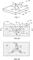
- FIG. 1 is a block diagram that illustrates an implant 100 in accordance with one or more embodiments of the present technique.
- implant 100 may include a large joint implant (e.g., a hip and/or knee implant), a small joint implant (e.g., shoulder, elbow and/or ankle implants), trauma implants (e.g., shoulder fracture, long bone reconstruction implants and/or intermedullary rod implants), a spine implant (e.g., fusion or dynamic implants), cranial maxi facial implant (e.g., jaw replacement), a dental implant, or the like.
- implant 100 may include an intervertebral implant to be implanted between end plates of two adjacent vertebras during a spinal implant procedure.
- implant 100 may include a fusion implant (e.g., a fusion cage) intended to rigidly fix the relative positions of two adjacent vertebrae, or and dynamic intervertebral device intended to couple to each of the two adjacent vertebrae and to facilitate motion (e.g., flexion, extension, and/or lateral bending) between the two adjacent vertebrae.
- implant 100 may include one or more portions of an articulating knee implant.
- implant 100 may include an upper or lower portion of a knee implant that articulate relative to one another during use, where one or both of the upper and lower portions include bone-implant interfaces that couple implant 100 to bone structures of the knee.
- Implant 100 includes one or more bone-interfaces.
- implant 100 includes an implant body 102 having an upper bone-implant interface 104a and a lower bone-implant interface 104b.
- Implant 100 may include any number of bone-implant interfaces that provide for interface of the implant with bone structure.
- upper bone-implant interface 104a may contact and secure to a first adjacent bone structure during use and lower bone- implant interface 104b may contact and secure to a second adjacent bone structure during use.
- upper bone-implant interface 104a may couple to a portion of the first bone structure disposed above implant 100 and lower bone- implant interface 104b may couple to the second bone structure disposed below implant 100.
- the number and orientation of bone-implant interfaces for a given implant may vary based on the intended applications, and, thus, relative terms such as upper and lower are intended as exemplary and are not intended to be limiting.
- one or both of the upper and lower bone-implant interfaces 104a and 104b may be oriented such that they are disposed laterally (e.g., as right, left, back and/or front sides of implant body 102).
- body 102 may include any desirable implant construct for the given implant application.
- spinal implants or knee implants may include a shape, components, and a mechanical construct that provides for motion preservation.
- Bone-implant interfaces 104a and 104b include a contact surface.
- the term "contact surface” refers to a portion of an implant intended to be in contact or near contact with an adjacent structure (e.g., a bone structure) and/or to adhere/couple with the adjacent structure when implanted.
- a contact surface may include an interface plate of an implant, for instance.
- bone-implant interfaces 104a and 104b include an upper contact surface 106a and a lower contact surface 106b, respectively.
- Contact surfaces 106a and 106b includes portions of implant 100 that are intended to abut and/or integrate with adjacent bone structure when implant 100 is implanted.
- implant 100 includes a single contact surface or more than two contact surfaces. Contact surface(s) may take any suitable shape (e.g., a substantially flat planar surface, a curved/contoured surface, ridges, or the like).
- bone-implant interfaces includes a structure that facilitates coupling of implant 100 to adjacent bone structure.
- upper bone interface 104a includes contact surface 106a a rod structure 108 extending therefrom.
- rod structure 108 may be pressed into adjacent bone structures.
- implant 100 may be pressed against a bone structure such that rod structure 108 penetrates into the bone structure and contact face 106a is pressed against a corresponding surface the bone structure.
- rod structure 108 may be disposed in the bone structure as discussed in more detail below with respect to FIGS. 2A and 2B .
- some or all of the bone-implant interfaces of an implant include one or more rod structures.
- upper bone-implant interface 104a includes a rod structure 108 disposed thereon.
- rod structure 108 is illustrated on a single contact surface 106a of a single bone-implant interface 104a, other embodiments may include any number of rod structures disposed at any number of bone-implant interfaces and contact surfaces.
- implant 100 includes one or more rod structures disposed on one or both of upper and lower contact surfaces 106a and 106b of bone-implant interfaces 104a and 104b, respectively.
- Rod structures 108 disposed on both of upper and lower contact surfaces 106a and 106b may be of particular use where implant 100 is intended to span a gap/distance between two adjacent bone structures (e.g., implant 100 is sandwiched between the end plates of two adjacent vertebrae as discussed above).
- a rod structure includes at least two rod members (e.g., struts) that extend from a respective contact surface and define region (e.g., an opening or at least a partial opening) that enables bone through growth to facilitate coupling of the rod structure and, thus the implant, to the bone structure.
- rod structure 108 includes a space truss formed of three struts 110a, 110b and 110c.
- Struts 110a, 110b and 110c may each include substantially straight elongate rod members having a first end coupled to contact surface 106a and a second end coupled to each of the other struts at a vertex 112.
- Each face of the triangular shaped truss structure includes a planar truss unit having a triangular opening with a perimeter defined by two of struts 110a, 110b and 110c and the adjacent portion of contact face 106a.
- rod structure 108 includes a generally triangular shaped space truss that defines a four sided, substantially open region (e.g., opening/volume) 114.
- opening/volume 114 may facilitate bone growth through rod structure 108, thereby enhancing coupling and integration of implant 100 to the adjacent bone structure.
- at least a portion of rod structure 108 may be in contact or near contact with the adjacent bone structure, thereby enabling bone growth to extend into and/or through at least a portion of opening/volume 114 of truss structure 108 such that the bone growth interlocks with one or more struts 110a, 110b or 110c of rod structure 108.
- Interlocking of the bone growth and the struts 110a, 110b or 110c may rigidly fix implant 100 in a fixed location relative to the bone structure.
- FIG. 2A illustrates a side view of implant 100 of FIG, 1 implanted in a bone structure 120 in accordance with one or more embodiments of the present technique.
- FIG. 2B illustrates a cross-sectioned view of implant 100 implanted in a bone structure 120 of FIG. 2A taken across line 2B-2B in accordance with one or more embodiments of the present technique.
- rod structure 108 is disposed into bone structure 120 and contact surface 106a is pressed into contact with face 122 of bone structure 120.
- Bone structure 120 is disposed in volume 114 of rod structure 108.
- bone structure 120 may include bone through growth that grows around struts 110a, 110b and 110c and into opening/volume 114.
- bone structure 120 may include bone growth that encloses slits that are created in bone structure 120 during implanting of rod structure into bone structure 120.
- bone growth may provide for an interlock of rod structure 108 with bone structure 120 and may, thus, rigidly fix implant 100 in a fixed location relative to the bone structure 120.
- Rod structure 108 may effectively be 'grabbed' onto by the adjacent bone structure which enables integration of rod structure 108 with the adjacent bone structure 120.
- a force in the direction of arrow 124 acting upon implant 100 may be counteracted by a force in the direction of arrow 126 provided by bone structure 120 resisting movement of implant 100.
- implant 100 includes a knee implant force 124 may represent an "uplift" force.
- a net uplift may be the result of forces acting at a particular portion of implant.
- uplift may be the result of a downward force on implant 100 as represented by arrow 124a.
- bone structure 120 coupled to rod structure 108 and provided in volume 114 may inhibit implant 100 from moving upward in the direction of arrow 124.
- Similar resistance to lateral/shearing forces e.g., side to side motion, rotation motion, etc.
- the load transfer to bone structure 120 in volume 114 through the pulling of strut 110b and 110c in the direction of force 124 may encourage an increase in bone density through remodeling principles found in previously mentioned Wolfs law.
- coupling of surface to bone structure 120 e.g., enhanced via use of a biologic or porous coating
- rod structure 108 extends from contact surface 106a by a distance (e.g., height) that is less than, about the same, the same, or greater than a height/thickness of a body 102 of implant 100.
- rod structure 108 protrudes extends a distance that is about four times the height/thickness of implant body 102.
- rod structure 108 may have a height that is about 10%, 15%, 20%, 30%, 40%, 50%, 60%, 70%, 80%, 90%, 100%, 150%, 200%, 250%, 300%, 350%, 400%, 450%, 500%, 550% that of body 102 of implant 100.
- rod structure 108 may have a height that is about 1mm, 2mm, 3mm, 4mm, 5mm, 10mm, 15mm, 20mm, 25mm, 30mm, 40mm, 45mm, 50mm, 55mm, 60mm, 65mm, 70mm, 75mm, 80mm or greater.
- implant 100 may be pressed into contact with the adjacent bone structure such that at least a portion of rod structure 108 is disposed inside of the adjacent bone structure upon implantation.
- implant 100 may be pressed into contact with bone structure 120 such that vertex 112 pierces into the bone structure and is advanced such that at least a portion of struts 110a, 110b or 110c and opening/volume 114 extend into bone structure 120.
- Such a technique may encourage bone to grow into and/or through opening/volume 114.
- implant 100 may be advanced/pressed into bone structure 120 until the respective contact surface (e.g., upper contact surface 106a) is in contact or near contact with surface 122 of bone structure 120.
- a bone-implant interface e.g., the rod structure and/or the contact surfaces
- a material intend to promote bone growth and/or bone adherence and/or an antimicrobial to prevent infection via the rod structure and/or the contact surface.
- at least a portion of a bone- implant interface may be coated with a pain medication (e.g., analgesics) to reduce pain after insertion of the implant into the bone.
- a pain medication e.g., analgesics
- at least some or all of the surfaces of struts 110a, 110b or 110c and/or contact surfaces 106a and 106b may be coated with a biologic, a bone growth factor and/or pain medication.
- some or all the bone -implant interface may include a porous surface/coating that facilitates adherence of the contact surface to the adjacent bone structure.
- some or all of struts 110a, 110b and 110c and/or contact surfaces 106a and 106b may include a porous surface texture to promote bone growth that adheres to rod structure 108 and contact surfaces 106a and 106b.
- At least a portion of the adjacent bone structure in which a rod structure is to be implanted may be pierced/cut/slit prior to the rod structure being advanced/pressed into the adjacent bone structure.
- a bone end plate of a vertebra may be cut to accept struts 110a, 110b and 110c of rod structure 108.
- a cutting tool/edge may be used to cut into the adjacent bone structure such that the resulting cuts accommodate portions (e.g., one or more struts or rods) of rod structure 108.
- rod structure 108 includes a triangular shape, such as that depicted in FIGS. 1-2 A
- one or more complementary cuts may be made into the adjacent bone structure in a complementary Y-shaped pattern.
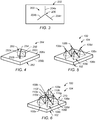
- FIG. 3 illustrates a cut 200 that may be provided in a bone structure 202 in accordance with one or more examples of the present technique.
- Bone structure 202 may be similar to bone structure 120.
- Cut 220 may be provided prior to or as a result of rod structure 108 being advanced/pressed into the adjacent bone structure 202.
- FIG. 3 may be representative of an end view of a bone structure.
- FIG. 3 may be illustrative of the face of a vertebra end plate and a Y-shaped cut extending into the face (e.g., looking upward/downward into the end plate of the vertebrae) that is shaped to accept at least a portion of rod structure 108.
- cut 200 may include one or more segments intended to accommodate one or more portions (e.g., struts or rods) of a rod structure.
- cut 200 includes three slits 204a, 204b and 204c formed in bone structure 202. Slits 204a, 204b and 204c may extend from the face of bone structure 202 into bone structure 202 in a direction substantially perpendicular to a face of bone structure 202 and/or substantially parallel to the intended direction of advancement of struts of rod structure 108 and/or implant 100 into bone structure 202.
- slits include cuts into the bone that do not require any bone material to be removed.
- a sharp cutting edge e.g., a knife/blade
- struts 110a, 110b or 110c may slide into slits 204a, 204b and 204c, respectively.
- Cut 200 may be complementary to the shape/orientation of portions (e.g., rods or struts) of rod structure 108.
- cut 200 may include four slits oriented at approximately ninety-degrees relative to one another.
- cut 200 may be formed by one or more complementary cutting members (e.g., knives/blades) that are pressed, slid, or otherwise advanced into bone structure 202.
- a cutting member includes one or more cutting edges arranged complementary to the profile of the portions (e.g., rods or struts) of rod structure 108 such that advancement of the cutting edge cuts one, a plurality, or all of the slits to accommodate rod structure 108 being advanced/pressed into the bone structure.
- FIG. 4 illustrates a cutting member 250 in accordance with one or more examples of the present technique.
- Cutting member 250 may include three cutting blades 252a, 252b and 252c oriented at approximately one-hundred twenty degrees relative to one another about a vertex 254.
- cutting members 252a, 252b and 252c are arranged complementary to slits 204a, 204b and 204c of cut 200 and/or struts 110a, 110b or 110c of rod structure 108.
- cutting member 250 may include four cutting blades oriented at approximately ninety-degrees relative to one another.
- the cutting blades of cutting member 250 may be advanced into bone structure 202 at a depth that is about the same or deeper than a height of rod structure 108. In some examples, the cutting blades may be advanced into bone structure 202 at a depth that is about the same or shallower than a height of rod structure 108. In some examples, a leading edge of the cutting blades may be shaped to be complementary to the shape of the struts.
- leading edge of one, a plurality, or all of cutting blades 252a, 252b and 252c may be angled similar to the angle of struts 110a, 110b or 110c extending from contact surface 106a, as illustrated by dashed line 256 which includes an angle substantially similar to that of a corresponding strut 110c of implant 100.
- cutting member 250 may be provided as an instrument that is advanced into bone structure 202.
- cutting member 250 may be integrated with or more other devices used during the implantation procedure.
- cutting member 250 may be coupled to a distractor typically positioned between the vertebrae and expanded to set the relative positions of adjacent vertebrae. The force of distraction may act to advance cutting member 250 into bone structure 202.
- FIG. 4 illustrates cutting member 250 disposed on a top surface 260a of a body 262 of a distractor 264, in accordance with one or more examples of the present technique.
- one or more cutting members may be disposed on other portions of an instruments (e.g., distractor 264), such as a bottom surface 206b.
- distractor 264 may be disposed between the adjacent bone structures (e.g., adjacent vertebrae) and expanded such that top and bottom surfaces 260a and 260b move away from one another, thereby pressing one or more of cutting members 250 (e.g., on top and/or bottom contact surfaces 260a and 260b) into the adjacent bone structure (e.g., 202) to form one or more cuts (e.g., cut 200) into the bone structure (e.g., end plates of the adjacent vertebrae), where the cuts are intended to accommodate struts (e.g., struts 110a, 110b and 110c) of the rod one or more structures (e.g., rod structure 108) of an implant (e.g., implant 100) to be engaged with the bone structure (e.g., bone structure 120 or 202).
- struts e.g., struts 110a, 110b and 110c
- a distractor may be used to increase a separation distance between two adjacent bone structures (e.g., between end plates of adjacent vertebrae).
- the distractor is unexpanded and/or removed, and the implant (e.g., 100) is disposed between the bone structures (e.g., in substantially the same position as the distractor) such that one or more rod structures are aligned/engaged with one or more of the resulting cuts.
- Other examples may include pressing or otherwise advancing cutting member 250 into a bone structure where a rod structure is to be disposed.
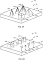
- FIG. 5 depicts bone -implant interface 104 including a plurality of rod structures 108a, 108b, 108c and 108d provided at upper contact surface 106a of implant 100 in accordance with one or more embodiments of the present technique.
- four rod structures 108a, 108b, 108c and 108d are disposed substantially adjacent one another on upper contact surface 106a of implant 100.
- Some or all struts of rod structures 108a, 108b, 108c and 108d may share at least one common vertex with another of rod structures 108a, 108b, 108c and 108d at the contact surface 106a.
- one, a plurality or all of rod structures are spaced apart from one another.
- one, a plurality, or all of rod structures 108a, 108b, 108c and 108d may not share a vertex at or near contact surface 106a.
- any number of rod structures may be provided on any portion of implant 100.
- the shape and orientation of the rod structures may be varied to mimic various desired shapes.
- the truss structures of rod structures 108a-108d may be varied in height and/or orientation to provide a curved profile similar to that of a ball and/or a socket of a joint.
- a bone-implant interface includes a plurality of rod structures stacked upon one another to form a web-like truss structure disposed on one or more contact surfaces of implant 100.
- FIG. 6 illustrates implant 100 having bone-implant interface 104 including a multi-layer rod-structure (e.g., truss/web structure) 270 in accordance with one or more embodiments of the present technique.
- Multilayer rod structure 270 is disposed at a bone-implant interface of implant 1000.
- multi-layer rod-structure 270 is disposed on contact surface 106a of implant 100.
- a multi-layer rod-structure includes a plurality of rod structures interconnected and/or stacked upon one another.
- the first layer of the stacked design may replace the 'height' of the primary bone structure and can be filled with a cement such as PMMA or bone void filler such as calcium phosphate which will remodel into bone over time.
- the second layer of the stacked structure may provide for fixation and load transferring.
- a triangular rod structure 108e is stacked atop vertices of rod structures 108b, 108c and 108d.
- the shape and orientation of the web structure 270 may be varied to mimic various desired shapes.
- web structure 270 may be varied in height and/or orientation to provide a curved profile similar to that of a ball and/or a socket of a joint.
- one or more additional rod members may be provided between one, a plurality, or all of the vertices of rod structures.
- struts 110d- 110h extend between vertices of rod structures 108a-108d.
- one or more struts may extend between some or all of the struts at or near the point where they are coupled to the contact face.
- one or more rod members/struts may extend in place of one or more of the dashed lines illustrated in FIGS. 1 , 4 and 5 .
- rod structure 108 includes a web/truss structure, such as those described in U.S. Provisional Patent Application No. 61/138707 entitled “TRUSS IMPLANT” by Jessee Hunt, filed December 18, 2008 and U.S. Patent Application No. 12/640,825 entitled “TRUSS IMPLANT” by Jessee Hunt, filed December 17, 2009.
- a rod structure includes a two-dimensional rod structure.
- FIGS. 7A-7G illustrate side views of exemplary two-dimensional rod structures 108f-108l in accordance with one or more embodiments of the present technique.
- FIG. 8 illustrates an isometric view of each of rod structures 108f-108l of FIGS. 7A-7G disposed on contact surface 106 of bone -implant interface 104 of implant 100 in accordance with one or more embodiments of the present technique.
- FIG. 7A includes a triangular shaped rod structure 108f that includes two rod members 110 each having ends coupled to one another at a vertex and coupled to contact surface 106 of body 102, defining an opening 114 through which bone growth may occur.
- Rod structure 108f may include a triangular-shaped planar truss.
- FIG. 7B includes a U-shaped rod structure 108g that includes a curved rod member 110 having a U-shaped bend at its apex and having ends coupled to contact surface 106 of body 102, defining an opening 114 through which bone growth may occur.
- curved rod member 110 may include two or more portions (e.g., rod members) that form the U-shape. For example, a right curved portion may extend from contact surface 106, a left curved portion may extend from contact surface 106 and the two portions may be coupled to one another at an apex of rod structure 108g.
- FIG. 7C includes a U- shaped rod structure 108h that includes a plurality of substantially straight rod members 110 having a substantially straight rod member its apex and having two substantially straight rod members at either end coupled to contact surface 106 of body 102, defining an open region 114 through which bone growth may occur.
- FIG. 7D includes a L-shaped rod structure 108i that includes a first a substantially straight rod member 110 extending from contact surface 106 of body 102 and a second substantially straight rod member 110 oriented at an oblique angle (e.g., substantially perpendicular angle) to the first rod member 100.
- FIG. 1 includes a first a substantially straight rod member 110 extending from contact surface 106 of body 102 and a second substantially straight rod member 110 oriented at an oblique angle (e.g., substantially perpendicular angle) to the first rod member 100.
- 7E includes a hook/barb-shaped rod structure 108j that includes a first a substantially straight rod member 110 extending from contact surface 106 of body 102 and a second substantially straight rod member 110 oriented at an oblique angle (e.g., an acute angle of about forty-five degrees) relative to the first rod member 110.
- a hook/barb-shaped rod structure 108j that includes a first a substantially straight rod member 110 extending from contact surface 106 of body 102 and a second substantially straight rod member 110 oriented at an oblique angle (e.g., an acute angle of about forty-five degrees) relative to the first rod member 110.
- Other embodiments may include various angles of the second rod member relative to the first rod member from about ten degrees to about one hundred seventy degrees (e.g., a second rod member angled oblique about ten, twenty, thirty, forty, fifty, sixty, seventy, eighty, ninety, one hundred, one hundred ten, one hundred twenty, one hundred thirty, one hundred forty, one hundred fifty, one hundred sixty, and/or one seventy degrees relative to the first rod member).
- 7F includes a hook-shaped rod structure 108k that includes a first a substantially straight rod member 110 extending from contact surface 106 of body 102, a second substantially straight rod member 110 oriented at an oblique angle (e.g., substantially perpendicular angle) to the first rod member 100, and a third substantially straight rod member 110 oriented substantially parallel to the first rod member 110.
- a hook-shaped rod structure 108k that includes a first a substantially straight rod member 110 extending from contact surface 106 of body 102, a second substantially straight rod member 110 oriented at an oblique angle (e.g., substantially perpendicular angle) to the first rod member 100, and a third substantially straight rod member 110 oriented substantially parallel to the first rod member 110.
- Other embodiments may include various angles of the second rod member relative to the first rod member (e.g., a second member angled oblique from about ten degrees to about one-hundred seventy degrees relative to the first rod member - a second member angled oblique about ten, twenty, thirty, forty, fifty, sixty, seventy, eighty, ninety, one hundred, one hundred ten, one hundred twenty, one hundred thirty, one hundred forty, one hundred fifty, one hundred sixty, and/or one seventy degrees relative to the first member) and various angles of the third rod member relative to the second rod member (e.g., a third rod member angled oblique from about ten degrees to about one-hundred seventy degrees relative to the second rod member - a third member angled oblique about ten, twenty, thirty, forty, fifty, sixty, seventy, eighty, ninety, one hundred, one hundred ten, one hundred twenty, one hundred thirty, one hundred forty, one hundred fifty, one hundred sixty, and
- FIG. 7G includes a hook-shaped rod structure 1081 that includes a rod member having a rounded end curved back towards contact surface 106 of body 102.
- rod structure 1081 may include rod member 100 having a longitudinal axis that is curved at least at one end to provide a rounded bend that forms a hook-like shape.
- the bend may include a bend from about ten degrees to about one hundred eighty degrees, as depicted, or more.
- a rod structure may include a three-dimensional rod structure.
- rod structure may include one or more three-sided triangular shaped space truss structure similar that of rod structure 108 described above with respect to FIGS 1-6 .
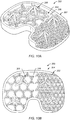
- FIGS. 9A-9B illustrate isometric views of a plurality of exemplary three-dimensional rod structures 108m-108w disposed on contact surfaces 106 of bone-implant interfaces 104 of implants 100 in accordance with one or more embodiments of the present technique.
- Rod structures 108m, 108n, 108n and 108p include a four-sided (e.g., pyramidal) space truss, five-sided space truss, six-sided space truss, and an eight sided space truss, respectively.
- Rod structure 108q includes a rectangular/square shaped rod structure formed from a plurality of rod members similar to those of rod structure 108h of FIG. 7C .
- Rod structure 108r includes an X-shaped rod structure formed from a plurality of rod members similar to those of rod structure 108h of FIG. 7C .
- Rod structure 108s includes an X-shaped rod structure formed from a plurality of curved rod members similar to those of rod structure 108g of FIG. 7B .
- Rod structure 108t includes a three hook (e.g., treble-hook) shaped rod structure formed from a plurality of rod structures similar to those of rod structure 108i of FIG. 7D .
- Rod structure 108u includes a treble-hook shaped rod structure formed from a plurality of rod structures similar to those of rod structure 108j of FIG. 7E .
- Rod structure 108v includes a treble-hook shaped rod structure formed from a plurality of rod structures similar to those of rod structure 108k of FIG. 7F .
- Rod structure 108w includes a treble-hook shaped rod structure formed from a plurality of rod structures similar to those of rod structure 1081 of FIG. 7G .
- Rod structure 108x includes an S-shaped rod structure formed from a plurality of rod members similar to those of rod structure 108h of FIG. 7C disposed in a repetitive pattern. Other embodiments may include a random pattern and/or may include a pattern that includes some or all of the other shapes and arrangements of rod structures (e.g., 108-108w) described herein.
- any of the rod structures described herein may be formed via coupling of a plurality of rod members or may be formed of a single rod member that is bent/formed/molded into the provided shape.
- rod members e.g., struts
- a rod structure may have an overall length or width of less than about 1 inch (e.g., a length less than about 0.9 in, 0.8 in, 0.7 in, 0.6 in, 0.5 in, 0.4 in, 0.3 in, 0.2 in, 0.1 in) , with 1 inch being equal to 2.54 cm.
- Embodiments may include rod structures having any variety of shapes.
- other embodiments may include a seven sided space truss and/or space trusses having more than eight sides.
- any type, size, number, or combination of number, types and sizes of rod structures may be provided on one, a plurality, or all of the contact faces of an implant as defined in claim 1.
- FIGS. 10A and 10B illustrate an isometric view and top view, respectively, of an exemplary implant 300 in accordance with one or more embodiments of the present technique.
- implant 300 includes a bone-implant interface 304 that includes a contact face 306 having a plurality of rod structures 308 extending therefrom.
- rod structures 308 include a plurality of different shapes and sizes.
- rod structures 308 include smaller sized triangular shaped space trusses, some of rod structures 308 include larger sized triangular shaped space trusses that extend between and above rod members of the smaller sized space trusses, and some of the rod structures 308 include struts arranges in a hexagonal pattern to form six-sided planar trusses of corresponding space trusses.
- implant 300 may include a lower portion of a knee implant.
- FIG. 11 A illustrates a side view of a knee implant 400 in accordance with one or more embodiments of the present technique.
- implant 400 includes an upper body 402a and a lower body 402b having bone-implant interfaces 404a and 404b respectively.
- Upper body 402a includes a cup that cradles bone structure 420a.
- one or both of bone-implant interfaces 404a and 404b includes a rod structure.
- interfaces 404a and 404b include rod structures 408a and 408b extending from contact surfaces 406a and 406b, respectively.
- rod structures may be used in conjunction with other forms and types of bone -implant interfaces, such as a rod or keel.
- upper body 402a may include an elongated rod 410a that is disposed into bone structure 420a and/or lower body 410 may include an elongated rod 410b that is disposed into bone structure 420b.
- Elongated rod may include a dowel rod, screw, keel or the like.
- implant 100 (e.g., implant body 102) includes a web/truss structure, such as those described in U.S. Provisional Patent Application No. 61/138707 entitled “TRUSS IMPLANT” by Jessee Hunt, filed December 18, 2008 and U.S. Patent Application No. 12/640,825 entitled “TRUSS IMPLANT” by Jessee Hunt, filed December 17, 2009.
- FIG. 12 illustrates a side view of an implant 500 in accordance with one or more embodiments of the present technique.
- implant 500 includes a body 502 having web/truss structure, and upper and lower bone-implant interfaces 504a and 504b that include a plurality of rod structures 508a and 508b extending from upper and lower contact surfaces 506a and 506b, respectively, of implant 500.
- Implant 500 may include a spinal implant (e.g., spinal fusion cage, vertebral body replacement (VBR) or spinal motion preservation implant) in some embodiments.
- spinal implant e.g., spinal fusion cage, vertebral body replacement (VBR) or spinal motion preservation implant
- upper bone-implant interface 504a may integrate with an endplate of an upper vertebrae (e.g., rod structures 508a may be pressed in the endplate of the upper vertebrae) and lower bone-implant interface 504b may integrate with an endplate of a lower vertebrae (e.g., rod structures 508b may be pressed in the endplate of the vertebrae).
- upper vertebrae e.g., rod structures 508a may be pressed in the endplate of the upper vertebrae
- lower bone-implant interface 504b may integrate with an endplate of a lower vertebrae (e.g., rod structures 508b may be pressed in the endplate of the vertebrae).
- FIG. 13 is a diagram that illustrates a shoulder implant 600 in accordance with one or more embodiments of the present technique.
- implant 600 includes a first body 602a and a second body 602b having bone-implant interfaces 604a and 604b respectively.
- one or both of bone-implant interfaces 604a and 604b includes a rod structure.
- interfaces 604a and 604b include rod structures 608a and 608b.
- only a rod interface is used to interface with bone.
- the elongated portion of body 602a may not be present and/or the screws of body 602b may not be present.
- FIG. 14 is a flowchart that illustrates an illustrative method 1000 - the method not falling under the scope of the present invention-of implanting an implant in accordance with one or more examples of the present technique.
- method 1000 includes preparing a bone structure, as depicted at block 1002, and inserting an implant (e.g., implant 100), as depicted at block 1002.
- preparing a bone structure includes positioning the bone structure.
- a distractor e.g., distractor 262 of FIG. 4
- preparing a bone structure includes cutting/slitting the bone structure to accommodate one or more struts of a rod structure of an implant to be coupled to the bone structure.
- a cutting member e.g., cutting member 250
- a cut e.g., cut 200
- distraction and cutting may be provided simultaneously via use of a distractor that includes one or more cutting members coupled to one or more of its contact faces (e.g., distractor 264 having cutting members 250 coupled to both upper and lower faces 206a and 206b).
- inserting the implant includes positioning the implant (e.g., implant 100) adjacent the bone structure (e.g., bone structure 202), aligning the rod structure (e.g., rod structure 108) with a complementary portion of the bone structure (e.g., cut 200) and/or advancing bone-implant interface (e.g., bone-implant interface 104, 104a or 104b) toward the bone structure such that at least the rod structure is in contact or near contact with the bone structure.
- the implant may be advanced until the contact surface (e.g., contact surfaces 106a and/or 106b) is in contact or near contact with the bone structure, such that at least portion or substantially all of the rod structure is disposed in the bone structure.
- substantially all of the struts of the truss structure 108 may be disposed in the slits 204a, 204b and 204c provided in the bone structure.
- method 1000 is exemplary and is not intended to be limiting. One or more of the elements described may be performed concurrently, in a different order than shown, or may be omitted entirely.
- Method 1000 may include any number of variations.
- rod/struts of rod structure 108 may include a sharp/thin profile such that minimal preparation of the bone structure needed (e.g., cuts do not need to be provided in the bone structure) as the struts of the rod structure may pierce/slice the bone structure as the implant is advanced into contact with the bone surface. Accordingly, in some examples, steps 1002 and 1004 of method 1000 may be combined into a single step.
Landscapes
- Health & Medical Sciences (AREA)
- Orthopedic Medicine & Surgery (AREA)
- Engineering & Computer Science (AREA)
- Biomedical Technology (AREA)
- Transplantation (AREA)
- Heart & Thoracic Surgery (AREA)
- Oral & Maxillofacial Surgery (AREA)
- Cardiology (AREA)
- Vascular Medicine (AREA)
- Life Sciences & Earth Sciences (AREA)
- Animal Behavior & Ethology (AREA)
- General Health & Medical Sciences (AREA)
- Public Health (AREA)
- Veterinary Medicine (AREA)
- Neurology (AREA)
- Physical Education & Sports Medicine (AREA)
- Prostheses (AREA)
Applications Claiming Priority (2)
| Application Number | Priority Date | Filing Date | Title |
|---|---|---|---|
| US12/818,508 US20110313532A1 (en) | 2010-06-18 | 2010-06-18 | Bone implant interface system and method |
| PCT/US2011/040117 WO2011159587A1 (en) | 2010-06-18 | 2011-06-13 | Bone implant interface system and method |
Publications (2)
| Publication Number | Publication Date |
|---|---|
| EP2582327A1 EP2582327A1 (en) | 2013-04-24 |
| EP2582327B1 true EP2582327B1 (en) | 2020-12-23 |
Family
ID=44314521
Family Applications (1)
| Application Number | Title | Priority Date | Filing Date |
|---|---|---|---|
| EP11726306.1A Active EP2582327B1 (en) | 2010-06-18 | 2011-06-13 | Bone implant interface system |
Country Status (6)
| Country | Link |
|---|---|
| US (2) | US20110313532A1 (enExample) |
| EP (1) | EP2582327B1 (enExample) |
| JP (1) | JP5990516B2 (enExample) |
| AU (1) | AU2011267941B2 (enExample) |
| CA (1) | CA2803015C (enExample) |
| WO (1) | WO2011159587A1 (enExample) |
Families Citing this family (93)
| Publication number | Priority date | Publication date | Assignee | Title |
|---|---|---|---|---|
| ATE287307T1 (de) | 2002-11-08 | 2005-02-15 | Howmedica Osteonics Corp | Lasererzeugte poröse oberfläche |
| US20060147332A1 (en) | 2004-12-30 | 2006-07-06 | Howmedica Osteonics Corp. | Laser-produced porous structure |
| US8414648B2 (en) | 2004-08-09 | 2013-04-09 | Si-Bone Inc. | Apparatus, systems, and methods for achieving trans-iliac lumbar fusion |
| US9949843B2 (en) | 2004-08-09 | 2018-04-24 | Si-Bone Inc. | Apparatus, systems, and methods for the fixation or fusion of bone |
| US8986348B2 (en) | 2004-08-09 | 2015-03-24 | Si-Bone Inc. | Systems and methods for the fusion of the sacral-iliac joint |
| US20180228621A1 (en) | 2004-08-09 | 2018-08-16 | Mark A. Reiley | Apparatus, systems, and methods for the fixation or fusion of bone |
| US8425570B2 (en) | 2004-08-09 | 2013-04-23 | Si-Bone Inc. | Apparatus, systems, and methods for achieving anterior lumbar interbody fusion |
| US8728387B2 (en) | 2005-12-06 | 2014-05-20 | Howmedica Osteonics Corp. | Laser-produced porous surface |
| US9539097B2 (en) * | 2007-11-08 | 2017-01-10 | Linares Medical Devices, Llc | Hip and knee joint assemblies incorporating debris collection architecture between the ball and seat interface |
| US9700431B2 (en) * | 2008-08-13 | 2017-07-11 | Smed-Ta/Td, Llc | Orthopaedic implant with porous structural member |
| US10842645B2 (en) | 2008-08-13 | 2020-11-24 | Smed-Ta/Td, Llc | Orthopaedic implant with porous structural member |
| PL2358309T3 (pl) | 2008-12-18 | 2016-04-29 | 4 Web Inc | Implant o strukturze kratownicowej |
| US12279964B2 (en) | 2008-12-18 | 2025-04-22 | 4Web, Llc | Implants having bone growth promoting agents and methods of using such implants to repair bone structures |
| US8715356B2 (en) * | 2010-04-13 | 2014-05-06 | Biomet Manufacturing, Llc | Prosthetic having a modular soft tissue fixation mechanism |
| US8709092B2 (en) | 2011-02-16 | 2014-04-29 | Genesis Medical Devices, LLC | Periprosthetic fracture management enhancements |
| US9186252B2 (en) * | 2011-07-26 | 2015-11-17 | Rita Leibinger GmbH & Co. KG | Tibia implant for tightening the patella tendons |
| DE102011079821A1 (de) | 2011-07-26 | 2013-01-31 | Rita Leibinger GmbH & Co. KG | Tibiaimplantat zur Straffung der Kniescheibenbänder |
| HK1205902A1 (zh) | 2012-03-09 | 2015-12-31 | Si-Bone, Inc | 結合植入物 |
| US10363140B2 (en) | 2012-03-09 | 2019-07-30 | Si-Bone Inc. | Systems, device, and methods for joint fusion |
| US9180010B2 (en) | 2012-04-06 | 2015-11-10 | Howmedica Osteonics Corp. | Surface modified unit cell lattice structures for optimized secure freeform fabrication |
| US9135374B2 (en) | 2012-04-06 | 2015-09-15 | Howmedica Osteonics Corp. | Surface modified unit cell lattice structures for optimized secure freeform fabrication |
| IN2014DN08676A (enExample) | 2012-05-04 | 2015-05-22 | Si Bone Inc | |
| WO2013181375A1 (en) * | 2012-05-30 | 2013-12-05 | New York University | Tissue repair devices and scaffolds |
| US9415137B2 (en) * | 2012-08-22 | 2016-08-16 | Biomet Manufacturing, Llc. | Directional porous coating |
| US20210228360A1 (en) | 2012-09-25 | 2021-07-29 | 4Web, Inc. | Sacroiliac joint fusion systems and methods |
| US12115071B2 (en) | 2012-09-25 | 2024-10-15 | 4Web, Llc | Programmable intramedullary implants and methods of using programmable intramedullary implants to repair bone structures |
| US9271845B2 (en) | 2012-09-25 | 2016-03-01 | 4Web | Programmable implants and methods of using programmable implants to repair bone structures |
| US9936983B2 (en) | 2013-03-15 | 2018-04-10 | Si-Bone Inc. | Implants for spinal fixation or fusion |
| US8974538B2 (en) | 2013-03-15 | 2015-03-10 | Steven M. Teeny | Orthopedic spacer |
| EP4458325A3 (en) | 2013-03-15 | 2025-01-22 | 4-web, Inc. | Traumatic bone fracture repair systems |
| US9839448B2 (en) | 2013-10-15 | 2017-12-12 | Si-Bone Inc. | Implant placement |
| US11147688B2 (en) | 2013-10-15 | 2021-10-19 | Si-Bone Inc. | Implant placement |
| CN104207867B (zh) * | 2014-08-13 | 2017-02-22 | 中国科学院福建物质结构研究所 | 一种低模量医用植入多孔支架结构 |
| US11090168B2 (en) * | 2014-08-29 | 2021-08-17 | Newsouth Innovations Pty Limited | Fusion device |
| US9662157B2 (en) | 2014-09-18 | 2017-05-30 | Si-Bone Inc. | Matrix implant |
| US10166033B2 (en) | 2014-09-18 | 2019-01-01 | Si-Bone Inc. | Implants for bone fixation or fusion |
| AU2016200195B2 (en) | 2015-01-14 | 2020-07-02 | Vb Spine Us Opco Llc | Spinal implant with fluid delivery capabilities |
| AU2016200179B2 (en) | 2015-01-14 | 2020-09-17 | Stryker European Operations Holdings Llc | Spinal implant with porous and solid surfaces |
| US10070962B1 (en) | 2015-02-13 | 2018-09-11 | Nextstep Arthropedix, LLC | Medical implants having desired surface features and methods of manufacturing |
| US10376206B2 (en) | 2015-04-01 | 2019-08-13 | Si-Bone Inc. | Neuromonitoring systems and methods for bone fixation or fusion procedures |
| CN114259328A (zh) | 2015-04-29 | 2022-04-01 | 肌肉骨骼科学教育研究所有限公司 | 线圈状的植入物和系统及其使用方法 |
| US10449051B2 (en) | 2015-04-29 | 2019-10-22 | Institute for Musculoskeletal Science and Education, Ltd. | Implant with curved bone contacting elements |
| US10709570B2 (en) | 2015-04-29 | 2020-07-14 | Institute for Musculoskeletal Science and Education, Ltd. | Implant with a diagonal insertion axis |
| US10492921B2 (en) | 2015-04-29 | 2019-12-03 | Institute for Musculoskeletal Science and Education, Ltd. | Implant with arched bone contacting elements |
| CA2930123A1 (en) | 2015-05-18 | 2016-11-18 | Stryker European Holdings I, Llc | Partially resorbable implants and methods |
| EP3297553B1 (en) | 2015-05-22 | 2020-10-14 | Stryker European Operations Limited | Joint or segmental bone implant for deformity correction |
| EP3389570B1 (en) | 2015-12-16 | 2024-04-17 | Nuvasive, Inc. | Porous spinal fusion implant |
| DE102015226063A1 (de) | 2015-12-18 | 2017-06-22 | Aesculap Ag | Medizinisches Produkt sowie medizinisches Kit zur Anwendung bei der Behandlung, insbesondere zur Anwendung beim Auffüllen und/oder Verschluss, einer Knochenkavität |
| CA3011965A1 (en) | 2016-01-28 | 2017-08-03 | DePuy Synthes Products, Inc. | Splitting attachment for graft containment cage |
| FR3050927B1 (fr) * | 2016-05-03 | 2022-01-07 | Ldr Medical | Implant vertebral et insert pour implant vertebral |
| US10660764B2 (en) * | 2016-06-14 | 2020-05-26 | The Trustees Of The Stevens Institute Of Technology | Load sustaining bone scaffolds for spinal fusion utilizing hyperbolic struts and translational strength gradients |
| US11033394B2 (en) | 2016-10-25 | 2021-06-15 | Institute for Musculoskeletal Science and Education, Ltd. | Implant with multi-layer bone interfacing lattice |
| US10478312B2 (en) | 2016-10-25 | 2019-11-19 | Institute for Musculoskeletal Science and Education, Ltd. | Implant with protected fusion zones |
| CN107252365A (zh) * | 2017-01-16 | 2017-10-17 | 吴栋 | 一种人工关节股骨假体及其制备方法 |
| US10251744B2 (en) * | 2017-01-27 | 2019-04-09 | Onkos Surgical, Inc. | Soft tissue fixation device |
| EP3582722A4 (en) * | 2017-02-16 | 2021-03-17 | Paragon 28, Inc. | IMPLANTS, DEVICES, SYSTEMS, KITS AND IMPLEMENTATION METHODS |
| US10512549B2 (en) * | 2017-03-13 | 2019-12-24 | Institute for Musculoskeletal Science and Education, Ltd. | Implant with structural members arranged around a ring |
| US10357377B2 (en) | 2017-03-13 | 2019-07-23 | Institute for Musculoskeletal Science and Education, Ltd. | Implant with bone contacting elements having helical and undulating planar geometries |
| US10667924B2 (en) * | 2017-03-13 | 2020-06-02 | Institute for Musculoskeletal Science and Education, Ltd. | Corpectomy implant |
| US10213317B2 (en) | 2017-03-13 | 2019-02-26 | Institute for Musculoskeletal Science and Education | Implant with supported helical members |
| AU2018203479B2 (en) | 2017-05-18 | 2024-04-18 | Howmedica Osteonics Corp. | High fatigue strength porous structure |
| KR101806140B1 (ko) * | 2017-06-29 | 2017-12-15 | 주식회사 멘티스로지텍 | 삼차원 프린터로 출력된 단위 구조를 가진 척추 임플란트 |
| US10835388B2 (en) | 2017-09-20 | 2020-11-17 | Stryker European Operations Holdings Llc | Spinal implants |
| EP3769724B1 (en) | 2017-09-22 | 2022-03-02 | Encore Medical, L.P. dba DJO Surgical | Talar ankle implant |
| EP3687422A4 (en) | 2017-09-26 | 2021-09-22 | SI-Bone, Inc. | SYSTEMS AND PROCESSES FOR DECORTICATION OF THE SACROILIAC JOINT |
| US10940015B2 (en) * | 2017-11-21 | 2021-03-09 | Institute for Musculoskeletal Science and Education, Ltd. | Implant with improved flow characteristics |
| US10744001B2 (en) * | 2017-11-21 | 2020-08-18 | Institute for Musculoskeletal Science and Education, Ltd. | Implant with improved bone contact |
| EP3501432A1 (en) | 2017-12-20 | 2019-06-26 | Stryker European Holdings I, LLC | Joint instrumentation |
| US11103356B2 (en) * | 2018-01-22 | 2021-08-31 | DePuy Synthes Products, Inc. | Orthopaedic prosthesis having support structure |
| US10695192B2 (en) | 2018-01-31 | 2020-06-30 | Institute for Musculoskeletal Science and Education, Ltd. | Implant with internal support members |
| US20190298528A1 (en) | 2018-03-28 | 2019-10-03 | Derek P. LINDSEY | Threaded implants and methods of use across bone segments |
| RU2020135532A (ru) * | 2018-03-30 | 2022-05-04 | Депуи Синтез Продактс, Инк. | Текстуры поверхности трехмерных пористых структур для врастания кости и способы их изготовления |
| CN112704584B (zh) * | 2018-06-12 | 2022-02-22 | 深圳市立心科学有限公司 | 具有多个支柱的椎间融合器 |
| AU2019367508B2 (en) * | 2018-10-23 | 2025-02-27 | Nakashima Healthforce Co., Ltd. | Implant material and method for producing said implant material |
| US11369419B2 (en) | 2019-02-14 | 2022-06-28 | Si-Bone Inc. | Implants for spinal fixation and or fusion |
| WO2020168269A1 (en) | 2019-02-14 | 2020-08-20 | Si-Bone Inc. | Implants for spinal fixation and or fusion |
| CN113631122A (zh) * | 2019-02-28 | 2021-11-09 | 丽玛共同股份公司 | 膝假体的胫骨组分的胫骨基板(胫骨组分包括胫骨基板)及制造胫骨基板的方法 |
| US11123201B2 (en) | 2019-09-24 | 2021-09-21 | Additive Implants, Inc. | Intervertebral spacer |
| CA3155565A1 (en) * | 2019-09-25 | 2021-04-01 | Depuy Ireland Unlimited Company | Three-dimensional porous structures for bone ingrowth and methods for producing |
| EP4606354A1 (en) | 2019-10-30 | 2025-08-27 | 4-web, Inc. | Programmable intramedullary implants and methods of using programmable intramedullary implants to repair bone structures |
| WO2021097438A1 (en) | 2019-11-15 | 2021-05-20 | 4Web, Inc. | Piezoelectric coated implants and methods of using piezoelectric coated implants to repair bone structures |
| WO2021102429A1 (en) | 2019-11-21 | 2021-05-27 | Si-Bone Inc. | Rod coupling assemblies for bone stabilization constructs |
| AU2020392121B2 (en) | 2019-11-27 | 2025-05-22 | Si-Bone, Inc. | Bone stabilizing implants and methods of placement across SI joints |
| EP4072452A4 (en) | 2019-12-09 | 2023-12-20 | SI-Bone, Inc. | SACROILIAC JOINT STABILIZATION IMPLANTS AND METHODS OF IMPLANTATION |
| CA3183956A1 (en) | 2020-07-08 | 2022-01-13 | Jessee Hunt | Implants having bone growth promoting agents contained within biodegradable materials |
| BE1028795B1 (nl) * | 2020-11-12 | 2022-06-13 | Umc Utrecht Holding Bv | Acetabulair implantaat en werkwijze voor het vervormen van dit implantaat |
| EP4000555B1 (en) * | 2020-11-13 | 2024-07-10 | Common Sense Engineering and Consult | An anatomical dental implant arranged to be implanted in a naturally occurring cavity of the jawbone |
| JP2023553120A (ja) | 2020-12-09 | 2023-12-20 | エスアイ-ボーン・インコーポレイテッド | 仙腸関節安定化インプラントおよびインプラント方法 |
| WO2023102533A1 (en) | 2021-12-03 | 2023-06-08 | Si-Bone Inc. | Fusion cages and methods for sacro-iliac joint stabilization |
| WO2024161253A1 (en) * | 2023-01-31 | 2024-08-08 | Mathys Ag Bettlach | Endoprosthesis having improved primary stability |
| US12433733B2 (en) | 2023-08-15 | 2025-10-07 | Si-Bone Inc. | Pelvic stabilization implants, methods of use and manufacture |
| US20250134520A1 (en) | 2023-10-27 | 2025-05-01 | 4Web, Llc | Devices for securing implants to bone tissue |
| WO2025221089A1 (ko) * | 2024-04-16 | 2025-10-23 | (주)시지바이오 | 척추 유합용 임플란트 |
Citations (1)
| Publication number | Priority date | Publication date | Assignee | Title |
|---|---|---|---|---|
| WO2010080511A1 (en) * | 2008-12-18 | 2010-07-15 | 4-Web Spine, Inc. | Truss implant |
Family Cites Families (22)
| Publication number | Priority date | Publication date | Assignee | Title |
|---|---|---|---|---|
| US3840904A (en) * | 1973-04-30 | 1974-10-15 | R Tronzo | Acetabular cup prosthesis |
| DE3637314A1 (de) * | 1986-11-03 | 1988-05-11 | Lutz Biedermann | Platzhalter-implantat |
| DE4133877C1 (enExample) * | 1991-10-12 | 1993-05-19 | S + G Implants Gmbh, 2400 Luebeck, De | |
| DE4208247C1 (de) * | 1992-03-14 | 1993-10-14 | Eska Medical Gmbh & Co | Implantat als Knochenersatz |
| AU713540B2 (en) * | 1994-10-25 | 1999-12-02 | Osteonics Corp. | Interlocking structural elements and method for bone repair, augmentation and replacement |
| DE19543530C1 (de) * | 1995-11-22 | 1997-05-07 | Eska Implants Gmbh & Co | Implantat als Knochenersatz |
| US6991643B2 (en) * | 2000-12-20 | 2006-01-31 | Usgi Medical Inc. | Multi-barbed device for retaining tissue in apposition and methods of use |
| US6206924B1 (en) * | 1999-10-20 | 2001-03-27 | Interpore Cross Internat | Three-dimensional geometric bio-compatible porous engineered structure for use as a bone mass replacement or fusion augmentation device |
| US6660008B1 (en) * | 2001-06-07 | 2003-12-09 | Opus Medical, Inc. | Method and apparatus for attaching connective tissues to bone using a suture anchoring device |
| FI20010523A0 (fi) * | 2001-03-16 | 2001-03-16 | Yli Urpo Antti | Soolien, geelien ja niiden seosten käsittely |
| FR2833480B1 (fr) * | 2001-12-13 | 2004-01-30 | Fixano | Prothese d'articulation du poignet et jeu d'elements permettant de constituer cette prothese |
| US6712852B1 (en) * | 2002-09-30 | 2004-03-30 | Depuy Spine, Inc. | Laminoplasty cage |
| WO2005009729A2 (en) * | 2003-07-24 | 2005-02-03 | Tecomet, Inc. | Assembled non-random foams |
| US8062365B2 (en) * | 2003-08-04 | 2011-11-22 | Warsaw Orthopedic, Inc. | Bone supporting devices with bio-absorbable end members |
| US20050222683A1 (en) * | 2004-03-31 | 2005-10-06 | Sdgi Holdings | Shape memory alloy disc replacement device |
| WO2006116761A2 (en) * | 2005-04-27 | 2006-11-02 | Stout Medical Group, L.P. | Expandable support device and methods of use |
| US7569075B2 (en) * | 2005-08-26 | 2009-08-04 | Johnson James F | Thrust plate hip prosthesis |
| US8728387B2 (en) * | 2005-12-06 | 2014-05-20 | Howmedica Osteonics Corp. | Laser-produced porous surface |
| DE102005061932A1 (de) * | 2005-12-23 | 2007-07-05 | Biedermann Motech Gmbh | Mehrwandiger Platzhalter |
| EP2043563B1 (en) * | 2006-07-24 | 2019-07-17 | Centinel Spine Schweiz GmbH | Intervertebral implant with keel |
| DE102006047663A1 (de) * | 2006-09-29 | 2008-04-03 | Aesculap Ag & Co. Kg | Augmentationskomponente für Knochenimplantate |
| US8858636B2 (en) * | 2010-04-09 | 2014-10-14 | DePuy Synthes Products, LLC | Intervertebral implant |
-
2010
- 2010-06-18 US US12/818,508 patent/US20110313532A1/en not_active Abandoned
-
2011
- 2011-06-13 AU AU2011267941A patent/AU2011267941B2/en active Active
- 2011-06-13 US US13/805,231 patent/US20130158672A1/en not_active Abandoned
- 2011-06-13 CA CA2803015A patent/CA2803015C/en active Active
- 2011-06-13 JP JP2013515407A patent/JP5990516B2/ja active Active
- 2011-06-13 WO PCT/US2011/040117 patent/WO2011159587A1/en not_active Ceased
- 2011-06-13 EP EP11726306.1A patent/EP2582327B1/en active Active
Patent Citations (2)
| Publication number | Priority date | Publication date | Assignee | Title |
|---|---|---|---|---|
| WO2010080511A1 (en) * | 2008-12-18 | 2010-07-15 | 4-Web Spine, Inc. | Truss implant |
| EP2358309A1 (en) * | 2008-12-18 | 2011-08-24 | 4-web Spine, Inc. | Truss implant |
Also Published As
| Publication number | Publication date |
|---|---|
| CA2803015A1 (en) | 2011-12-22 |
| JP5990516B2 (ja) | 2016-09-14 |
| CA2803015C (en) | 2022-07-12 |
| EP2582327A1 (en) | 2013-04-24 |
| US20110313532A1 (en) | 2011-12-22 |
| AU2011267941B2 (en) | 2015-04-02 |
| US20130158672A1 (en) | 2013-06-20 |
| WO2011159587A1 (en) | 2011-12-22 |
| JP2013532025A (ja) | 2013-08-15 |
| AU2011267941A1 (en) | 2013-01-10 |
Similar Documents
| Publication | Publication Date | Title |
|---|---|---|
| EP2582327B1 (en) | Bone implant interface system | |
| US20130030529A1 (en) | Implant interface system and method | |
| US12263094B2 (en) | Implant having a shaft coated with a web structure | |
| AU2018201065B2 (en) | Method of length preservation during bone repair | |
| CA2911880C (en) | Traumatic bone fracture repair systems and methods | |
| US20170319344A1 (en) | Prosthetic implant for ball and socket joints and method of use | |
| EP4125650A1 (en) | Sacroiliac joint fusion systems and methods | |
| WO2013006778A2 (en) | Foot and ankle implant system and method |
Legal Events
| Date | Code | Title | Description |
|---|---|---|---|
| PUAI | Public reference made under article 153(3) epc to a published international application that has entered the european phase |
Free format text: ORIGINAL CODE: 0009012 |
|
| 17P | Request for examination filed |
Effective date: 20130117 |
|
| AK | Designated contracting states |
Kind code of ref document: A1 Designated state(s): AL AT BE BG CH CY CZ DE DK EE ES FI FR GB GR HR HU IE IS IT LI LT LU LV MC MK MT NL NO PL PT RO RS SE SI SK SM TR |
|
| DAX | Request for extension of the european patent (deleted) | ||
| 17Q | First examination report despatched |
Effective date: 20160107 |
|
| STAA | Information on the status of an ep patent application or granted ep patent |
Free format text: STATUS: EXAMINATION IS IN PROGRESS |
|
| GRAP | Despatch of communication of intention to grant a patent |
Free format text: ORIGINAL CODE: EPIDOSNIGR1 |
|
| STAA | Information on the status of an ep patent application or granted ep patent |
Free format text: STATUS: GRANT OF PATENT IS INTENDED |
|
| INTG | Intention to grant announced |
Effective date: 20200715 |
|
| GRAS | Grant fee paid |
Free format text: ORIGINAL CODE: EPIDOSNIGR3 |
|
| GRAA | (expected) grant |
Free format text: ORIGINAL CODE: 0009210 |
|
| STAA | Information on the status of an ep patent application or granted ep patent |
Free format text: STATUS: THE PATENT HAS BEEN GRANTED |
|
| AK | Designated contracting states |
Kind code of ref document: B1 Designated state(s): AL AT BE BG CH CY CZ DE DK EE ES FI FR GB GR HR HU IE IS IT LI LT LU LV MC MK MT NL NO PL PT RO RS SE SI SK SM TR |
|
| REG | Reference to a national code |
Ref country code: GB Ref legal event code: FG4D |
|
| REG | Reference to a national code |
Ref country code: DE Ref legal event code: R096 Ref document number: 602011069724 Country of ref document: DE |
|
| REG | Reference to a national code |
Ref country code: AT Ref legal event code: REF Ref document number: 1346982 Country of ref document: AT Kind code of ref document: T Effective date: 20210115 |
|
| REG | Reference to a national code |
Ref country code: IE Ref legal event code: FG4D |
|
| PG25 | Lapsed in a contracting state [announced via postgrant information from national office to epo] |
Ref country code: GR Free format text: LAPSE BECAUSE OF FAILURE TO SUBMIT A TRANSLATION OF THE DESCRIPTION OR TO PAY THE FEE WITHIN THE PRESCRIBED TIME-LIMIT Effective date: 20210324 Ref country code: NO Free format text: LAPSE BECAUSE OF FAILURE TO SUBMIT A TRANSLATION OF THE DESCRIPTION OR TO PAY THE FEE WITHIN THE PRESCRIBED TIME-LIMIT Effective date: 20210323 Ref country code: RS Free format text: LAPSE BECAUSE OF FAILURE TO SUBMIT A TRANSLATION OF THE DESCRIPTION OR TO PAY THE FEE WITHIN THE PRESCRIBED TIME-LIMIT Effective date: 20201223 Ref country code: FI Free format text: LAPSE BECAUSE OF FAILURE TO SUBMIT A TRANSLATION OF THE DESCRIPTION OR TO PAY THE FEE WITHIN THE PRESCRIBED TIME-LIMIT Effective date: 20201223 |
|
| REG | Reference to a national code |
Ref country code: AT Ref legal event code: MK05 Ref document number: 1346982 Country of ref document: AT Kind code of ref document: T Effective date: 20201223 |
|
| REG | Reference to a national code |
Ref country code: NL Ref legal event code: MP Effective date: 20201223 |
|
| PG25 | Lapsed in a contracting state [announced via postgrant information from national office to epo] |
Ref country code: SE Free format text: LAPSE BECAUSE OF FAILURE TO SUBMIT A TRANSLATION OF THE DESCRIPTION OR TO PAY THE FEE WITHIN THE PRESCRIBED TIME-LIMIT Effective date: 20201223 Ref country code: LV Free format text: LAPSE BECAUSE OF FAILURE TO SUBMIT A TRANSLATION OF THE DESCRIPTION OR TO PAY THE FEE WITHIN THE PRESCRIBED TIME-LIMIT Effective date: 20201223 Ref country code: BG Free format text: LAPSE BECAUSE OF FAILURE TO SUBMIT A TRANSLATION OF THE DESCRIPTION OR TO PAY THE FEE WITHIN THE PRESCRIBED TIME-LIMIT Effective date: 20210323 |
|
| PG25 | Lapsed in a contracting state [announced via postgrant information from national office to epo] |
Ref country code: NL Free format text: LAPSE BECAUSE OF FAILURE TO SUBMIT A TRANSLATION OF THE DESCRIPTION OR TO PAY THE FEE WITHIN THE PRESCRIBED TIME-LIMIT Effective date: 20201223 Ref country code: HR Free format text: LAPSE BECAUSE OF FAILURE TO SUBMIT A TRANSLATION OF THE DESCRIPTION OR TO PAY THE FEE WITHIN THE PRESCRIBED TIME-LIMIT Effective date: 20201223 |
|
| REG | Reference to a national code |
Ref country code: LT Ref legal event code: MG9D |
|
| PG25 | Lapsed in a contracting state [announced via postgrant information from national office to epo] |
Ref country code: PT Free format text: LAPSE BECAUSE OF FAILURE TO SUBMIT A TRANSLATION OF THE DESCRIPTION OR TO PAY THE FEE WITHIN THE PRESCRIBED TIME-LIMIT Effective date: 20210423 Ref country code: RO Free format text: LAPSE BECAUSE OF FAILURE TO SUBMIT A TRANSLATION OF THE DESCRIPTION OR TO PAY THE FEE WITHIN THE PRESCRIBED TIME-LIMIT Effective date: 20201223 Ref country code: SK Free format text: LAPSE BECAUSE OF FAILURE TO SUBMIT A TRANSLATION OF THE DESCRIPTION OR TO PAY THE FEE WITHIN THE PRESCRIBED TIME-LIMIT Effective date: 20201223 Ref country code: LT Free format text: LAPSE BECAUSE OF FAILURE TO SUBMIT A TRANSLATION OF THE DESCRIPTION OR TO PAY THE FEE WITHIN THE PRESCRIBED TIME-LIMIT Effective date: 20201223 Ref country code: EE Free format text: LAPSE BECAUSE OF FAILURE TO SUBMIT A TRANSLATION OF THE DESCRIPTION OR TO PAY THE FEE WITHIN THE PRESCRIBED TIME-LIMIT Effective date: 20201223 Ref country code: CZ Free format text: LAPSE BECAUSE OF FAILURE TO SUBMIT A TRANSLATION OF THE DESCRIPTION OR TO PAY THE FEE WITHIN THE PRESCRIBED TIME-LIMIT Effective date: 20201223 Ref country code: SM Free format text: LAPSE BECAUSE OF FAILURE TO SUBMIT A TRANSLATION OF THE DESCRIPTION OR TO PAY THE FEE WITHIN THE PRESCRIBED TIME-LIMIT Effective date: 20201223 |
|
| PG25 | Lapsed in a contracting state [announced via postgrant information from national office to epo] |
Ref country code: AT Free format text: LAPSE BECAUSE OF FAILURE TO SUBMIT A TRANSLATION OF THE DESCRIPTION OR TO PAY THE FEE WITHIN THE PRESCRIBED TIME-LIMIT Effective date: 20201223 Ref country code: PL Free format text: LAPSE BECAUSE OF FAILURE TO SUBMIT A TRANSLATION OF THE DESCRIPTION OR TO PAY THE FEE WITHIN THE PRESCRIBED TIME-LIMIT Effective date: 20201223 |
|
| REG | Reference to a national code |
Ref country code: DE Ref legal event code: R097 Ref document number: 602011069724 Country of ref document: DE |
|
| PG25 | Lapsed in a contracting state [announced via postgrant information from national office to epo] |
Ref country code: IS Free format text: LAPSE BECAUSE OF FAILURE TO SUBMIT A TRANSLATION OF THE DESCRIPTION OR TO PAY THE FEE WITHIN THE PRESCRIBED TIME-LIMIT Effective date: 20210423 |
|
| PG25 | Lapsed in a contracting state [announced via postgrant information from national office to epo] |
Ref country code: AL Free format text: LAPSE BECAUSE OF FAILURE TO SUBMIT A TRANSLATION OF THE DESCRIPTION OR TO PAY THE FEE WITHIN THE PRESCRIBED TIME-LIMIT Effective date: 20201223 Ref country code: IT Free format text: LAPSE BECAUSE OF FAILURE TO SUBMIT A TRANSLATION OF THE DESCRIPTION OR TO PAY THE FEE WITHIN THE PRESCRIBED TIME-LIMIT Effective date: 20201223 |
|
| PLBE | No opposition filed within time limit |
Free format text: ORIGINAL CODE: 0009261 |
|
| STAA | Information on the status of an ep patent application or granted ep patent |
Free format text: STATUS: NO OPPOSITION FILED WITHIN TIME LIMIT |
|
| PG25 | Lapsed in a contracting state [announced via postgrant information from national office to epo] |
Ref country code: ES Free format text: LAPSE BECAUSE OF FAILURE TO SUBMIT A TRANSLATION OF THE DESCRIPTION OR TO PAY THE FEE WITHIN THE PRESCRIBED TIME-LIMIT Effective date: 20201223 Ref country code: DK Free format text: LAPSE BECAUSE OF FAILURE TO SUBMIT A TRANSLATION OF THE DESCRIPTION OR TO PAY THE FEE WITHIN THE PRESCRIBED TIME-LIMIT Effective date: 20201223 |
|
| 26N | No opposition filed |
Effective date: 20210924 |
|
| PG25 | Lapsed in a contracting state [announced via postgrant information from national office to epo] |
Ref country code: MC Free format text: LAPSE BECAUSE OF FAILURE TO SUBMIT A TRANSLATION OF THE DESCRIPTION OR TO PAY THE FEE WITHIN THE PRESCRIBED TIME-LIMIT Effective date: 20201223 |
|
| REG | Reference to a national code |
Ref country code: CH Ref legal event code: PL |
|
| PG25 | Lapsed in a contracting state [announced via postgrant information from national office to epo] |
Ref country code: SI Free format text: LAPSE BECAUSE OF FAILURE TO SUBMIT A TRANSLATION OF THE DESCRIPTION OR TO PAY THE FEE WITHIN THE PRESCRIBED TIME-LIMIT Effective date: 20201223 |
|
| REG | Reference to a national code |
Ref country code: BE Ref legal event code: MM Effective date: 20210630 |
|
| PG25 | Lapsed in a contracting state [announced via postgrant information from national office to epo] |
Ref country code: LU Free format text: LAPSE BECAUSE OF NON-PAYMENT OF DUE FEES Effective date: 20210613 |
|
| PG25 | Lapsed in a contracting state [announced via postgrant information from national office to epo] |
Ref country code: LI Free format text: LAPSE BECAUSE OF NON-PAYMENT OF DUE FEES Effective date: 20210630 Ref country code: IE Free format text: LAPSE BECAUSE OF NON-PAYMENT OF DUE FEES Effective date: 20210613 Ref country code: CH Free format text: LAPSE BECAUSE OF NON-PAYMENT OF DUE FEES Effective date: 20210630 |
|
| PG25 | Lapsed in a contracting state [announced via postgrant information from national office to epo] |
Ref country code: IS Free format text: LAPSE BECAUSE OF FAILURE TO SUBMIT A TRANSLATION OF THE DESCRIPTION OR TO PAY THE FEE WITHIN THE PRESCRIBED TIME-LIMIT Effective date: 20210423 |
|
| PG25 | Lapsed in a contracting state [announced via postgrant information from national office to epo] |
Ref country code: BE Free format text: LAPSE BECAUSE OF NON-PAYMENT OF DUE FEES Effective date: 20210630 |
|
| PG25 | Lapsed in a contracting state [announced via postgrant information from national office to epo] |
Ref country code: HU Free format text: LAPSE BECAUSE OF FAILURE TO SUBMIT A TRANSLATION OF THE DESCRIPTION OR TO PAY THE FEE WITHIN THE PRESCRIBED TIME-LIMIT; INVALID AB INITIO Effective date: 20110613 Ref country code: CY Free format text: LAPSE BECAUSE OF FAILURE TO SUBMIT A TRANSLATION OF THE DESCRIPTION OR TO PAY THE FEE WITHIN THE PRESCRIBED TIME-LIMIT Effective date: 20201223 |
|
| PG25 | Lapsed in a contracting state [announced via postgrant information from national office to epo] |
Ref country code: MK Free format text: LAPSE BECAUSE OF FAILURE TO SUBMIT A TRANSLATION OF THE DESCRIPTION OR TO PAY THE FEE WITHIN THE PRESCRIBED TIME-LIMIT Effective date: 20201223 |
|
| PG25 | Lapsed in a contracting state [announced via postgrant information from national office to epo] |
Ref country code: MT Free format text: LAPSE BECAUSE OF FAILURE TO SUBMIT A TRANSLATION OF THE DESCRIPTION OR TO PAY THE FEE WITHIN THE PRESCRIBED TIME-LIMIT Effective date: 20201223 |
|
| PGFP | Annual fee paid to national office [announced via postgrant information from national office to epo] |
Ref country code: DE Payment date: 20250627 Year of fee payment: 15 |
|
| PGFP | Annual fee paid to national office [announced via postgrant information from national office to epo] |
Ref country code: GB Payment date: 20250627 Year of fee payment: 15 |
|
| PGFP | Annual fee paid to national office [announced via postgrant information from national office to epo] |
Ref country code: FR Payment date: 20250625 Year of fee payment: 15 |
|
| PG25 | Lapsed in a contracting state [announced via postgrant information from national office to epo] |
Ref country code: TR Free format text: LAPSE BECAUSE OF FAILURE TO SUBMIT A TRANSLATION OF THE DESCRIPTION OR TO PAY THE FEE WITHIN THE PRESCRIBED TIME-LIMIT Effective date: 20201223 |