EP3297553B1 - Joint or segmental bone implant for deformity correction - Google Patents
Joint or segmental bone implant for deformity correction Download PDFInfo
- Publication number
- EP3297553B1 EP3297553B1 EP16729417.2A EP16729417A EP3297553B1 EP 3297553 B1 EP3297553 B1 EP 3297553B1 EP 16729417 A EP16729417 A EP 16729417A EP 3297553 B1 EP3297553 B1 EP 3297553B1
- Authority
- EP
- European Patent Office
- Prior art keywords
- implant
- bone
- component
- talus
- tibia
- Prior art date
- Legal status (The legal status is an assumption and is not a legal conclusion. Google has not performed a legal analysis and makes no representation as to the accuracy of the status listed.)
- Active
Links
- 239000007943 implant Substances 0.000 title claims description 112
- 210000000988 bone and bone Anatomy 0.000 title description 60
- 238000012937 correction Methods 0.000 title description 3
- 210000000544 articulatio talocruralis Anatomy 0.000 claims description 24
- 210000002303 tibia Anatomy 0.000 claims description 14
- 210000004233 talus Anatomy 0.000 claims description 13
- 210000003108 foot joint Anatomy 0.000 description 21
- 230000008468 bone growth Effects 0.000 description 14
- 239000000463 material Substances 0.000 description 8
- 239000003102 growth factor Substances 0.000 description 5
- 238000000034 method Methods 0.000 description 4
- 239000004696 Poly ether ether ketone Substances 0.000 description 3
- 210000003423 ankle Anatomy 0.000 description 3
- 210000002683 foot Anatomy 0.000 description 3
- 229920002530 polyetherether ketone Polymers 0.000 description 3
- 230000008569 process Effects 0.000 description 3
- 238000000110 selective laser sintering Methods 0.000 description 3
- 238000007792 addition Methods 0.000 description 2
- 238000000149 argon plasma sintering Methods 0.000 description 2
- 238000005266 casting Methods 0.000 description 2
- 230000012010 growth Effects 0.000 description 2
- 238000002513 implantation Methods 0.000 description 2
- 238000001746 injection moulding Methods 0.000 description 2
- 238000002844 melting Methods 0.000 description 2
- 230000008018 melting Effects 0.000 description 2
- 238000012986 modification Methods 0.000 description 2
- 230000004048 modification Effects 0.000 description 2
- 229920000642 polymer Polymers 0.000 description 2
- 102000004169 proteins and genes Human genes 0.000 description 2
- 108090000623 proteins and genes Proteins 0.000 description 2
- VYZAMTAEIAYCRO-UHFFFAOYSA-N Chromium Chemical compound [Cr] VYZAMTAEIAYCRO-UHFFFAOYSA-N 0.000 description 1
- 102000003971 Fibroblast Growth Factor 1 Human genes 0.000 description 1
- 108090000386 Fibroblast Growth Factor 1 Proteins 0.000 description 1
- 102000003974 Fibroblast growth factor 2 Human genes 0.000 description 1
- 108090000379 Fibroblast growth factor 2 Proteins 0.000 description 1
- 241000282412 Homo Species 0.000 description 1
- 108090000723 Insulin-Like Growth Factor I Proteins 0.000 description 1
- 241001465754 Metazoa Species 0.000 description 1
- 102000010780 Platelet-Derived Growth Factor Human genes 0.000 description 1
- 108010038512 Platelet-Derived Growth Factor Proteins 0.000 description 1
- 102000013275 Somatomedins Human genes 0.000 description 1
- 229910001069 Ti alloy Inorganic materials 0.000 description 1
- 102000004887 Transforming Growth Factor beta Human genes 0.000 description 1
- 108090001012 Transforming Growth Factor beta Proteins 0.000 description 1
- 230000002378 acidificating effect Effects 0.000 description 1
- 239000004599 antimicrobial Substances 0.000 description 1
- 208000037873 arthrodesis Diseases 0.000 description 1
- 239000000560 biocompatible material Substances 0.000 description 1
- 230000024245 cell differentiation Effects 0.000 description 1
- 230000010261 cell growth Effects 0.000 description 1
- 230000004663 cell proliferation Effects 0.000 description 1
- 239000000919 ceramic Substances 0.000 description 1
- 229910052804 chromium Inorganic materials 0.000 description 1
- 239000011651 chromium Substances 0.000 description 1
- 239000011248 coating agent Substances 0.000 description 1
- 238000000576 coating method Methods 0.000 description 1
- 229910017052 cobalt Inorganic materials 0.000 description 1
- 239000010941 cobalt Substances 0.000 description 1
- GUTLYIVDDKVIGB-UHFFFAOYSA-N cobalt atom Chemical compound [Co] GUTLYIVDDKVIGB-UHFFFAOYSA-N 0.000 description 1
- 230000000295 complement effect Effects 0.000 description 1
- 230000008878 coupling Effects 0.000 description 1
- 238000010168 coupling process Methods 0.000 description 1
- 238000005859 coupling reaction Methods 0.000 description 1
- 230000007547 defect Effects 0.000 description 1
- 238000013461 design Methods 0.000 description 1
- 238000002224 dissection Methods 0.000 description 1
- 238000010894 electron beam technology Methods 0.000 description 1
- 230000002708 enhancing effect Effects 0.000 description 1
- 210000000610 foot bone Anatomy 0.000 description 1
- 230000004927 fusion Effects 0.000 description 1
- 230000036541 health Effects 0.000 description 1
- 229910052588 hydroxylapatite Inorganic materials 0.000 description 1
- 208000015181 infectious disease Diseases 0.000 description 1
- 238000002347 injection Methods 0.000 description 1
- 239000007924 injection Substances 0.000 description 1
- 238000011068 loading method Methods 0.000 description 1
- 230000007774 longterm Effects 0.000 description 1
- 229910052751 metal Inorganic materials 0.000 description 1
- 239000002184 metal Substances 0.000 description 1
- 230000005012 migration Effects 0.000 description 1
- 238000013508 migration Methods 0.000 description 1
- XYJRXVWERLGGKC-UHFFFAOYSA-D pentacalcium;hydroxide;triphosphate Chemical compound [OH-].[Ca+2].[Ca+2].[Ca+2].[Ca+2].[Ca+2].[O-]P([O-])([O-])=O.[O-]P([O-])([O-])=O.[O-]P([O-])([O-])=O XYJRXVWERLGGKC-UHFFFAOYSA-D 0.000 description 1
- 239000011148 porous material Substances 0.000 description 1
- 238000005245 sintering Methods 0.000 description 1
- 239000010935 stainless steel Substances 0.000 description 1
- 229910001220 stainless steel Inorganic materials 0.000 description 1
- 239000003270 steroid hormone Substances 0.000 description 1
- 230000004936 stimulating effect Effects 0.000 description 1
- 239000000126 substance Substances 0.000 description 1
- 238000001356 surgical procedure Methods 0.000 description 1
- 210000001137 tarsal bone Anatomy 0.000 description 1
- ZRKFYGHZFMAOKI-QMGMOQQFSA-N tgfbeta Chemical compound C([C@H](NC(=O)[C@H](C(C)C)NC(=O)CNC(=O)[C@H](CCC(O)=O)NC(=O)[C@H](CCCNC(N)=N)NC(=O)[C@H](CC(N)=O)NC(=O)[C@H](CC(C)C)NC(=O)[C@H]([C@@H](C)O)NC(=O)[C@H](CCC(O)=O)NC(=O)[C@H]([C@@H](C)O)NC(=O)[C@H](CC(C)C)NC(=O)CNC(=O)[C@H](C)NC(=O)[C@H](CO)NC(=O)[C@H](CCC(N)=O)NC(=O)[C@@H](NC(=O)[C@H](C)NC(=O)[C@H](C)NC(=O)[C@@H](NC(=O)[C@H](CC(C)C)NC(=O)[C@@H](N)CCSC)C(C)C)[C@@H](C)CC)C(=O)N[C@@H]([C@@H](C)O)C(=O)N[C@@H](C(C)C)C(=O)N[C@@H](CC=1C=CC=CC=1)C(=O)N[C@@H](C)C(=O)N1[C@@H](CCC1)C(=O)N[C@@H]([C@@H](C)O)C(=O)N[C@@H](CC(N)=O)C(=O)N[C@@H](CCC(O)=O)C(=O)N[C@@H](C)C(=O)N[C@@H](CC=1C=CC=CC=1)C(=O)N[C@@H](CCCNC(N)=N)C(=O)N[C@@H](C)C(=O)N[C@@H](CC(C)C)C(=O)N1[C@@H](CCC1)C(=O)N1[C@@H](CCC1)C(=O)N[C@@H](CCCNC(N)=N)C(=O)N[C@@H](CCC(O)=O)C(=O)N[C@@H](CCCNC(N)=N)C(=O)N[C@@H](CO)C(=O)N[C@@H](CCCNC(N)=N)C(=O)N[C@@H](CC(C)C)C(=O)N[C@@H](CC(C)C)C(O)=O)C1=CC=C(O)C=C1 ZRKFYGHZFMAOKI-QMGMOQQFSA-N 0.000 description 1
- 210000001519 tissue Anatomy 0.000 description 1
- 229910021324 titanium aluminide Inorganic materials 0.000 description 1
- 238000003466 welding Methods 0.000 description 1
Images


Classifications
-
- A—HUMAN NECESSITIES
- A61—MEDICAL OR VETERINARY SCIENCE; HYGIENE
- A61F—FILTERS IMPLANTABLE INTO BLOOD VESSELS; PROSTHESES; DEVICES PROVIDING PATENCY TO, OR PREVENTING COLLAPSING OF, TUBULAR STRUCTURES OF THE BODY, e.g. STENTS; ORTHOPAEDIC, NURSING OR CONTRACEPTIVE DEVICES; FOMENTATION; TREATMENT OR PROTECTION OF EYES OR EARS; BANDAGES, DRESSINGS OR ABSORBENT PADS; FIRST-AID KITS
- A61F2/00—Filters implantable into blood vessels; Prostheses, i.e. artificial substitutes or replacements for parts of the body; Appliances for connecting them with the body; Devices providing patency to, or preventing collapsing of, tubular structures of the body, e.g. stents
- A61F2/02—Prostheses implantable into the body
- A61F2/30—Joints
- A61F2/46—Special tools or methods for implanting or extracting artificial joints, accessories, bone grafts or substitutes, or particular adaptations therefor
- A61F2/4603—Special tools or methods for implanting or extracting artificial joints, accessories, bone grafts or substitutes, or particular adaptations therefor for insertion or extraction of endoprosthetic joints or of accessories thereof
- A61F2/4606—Special tools or methods for implanting or extracting artificial joints, accessories, bone grafts or substitutes, or particular adaptations therefor for insertion or extraction of endoprosthetic joints or of accessories thereof of wrists or ankles; of hands, e.g. fingers; of feet, e.g. toes
-
- A—HUMAN NECESSITIES
- A61—MEDICAL OR VETERINARY SCIENCE; HYGIENE
- A61B—DIAGNOSIS; SURGERY; IDENTIFICATION
- A61B17/00—Surgical instruments, devices or methods, e.g. tourniquets
- A61B17/56—Surgical instruments or methods for treatment of bones or joints; Devices specially adapted therefor
- A61B17/58—Surgical instruments or methods for treatment of bones or joints; Devices specially adapted therefor for osteosynthesis, e.g. bone plates, screws, setting implements or the like
- A61B17/68—Internal fixation devices, including fasteners and spinal fixators, even if a part thereof projects from the skin
- A61B17/72—Intramedullary pins, nails or other devices
- A61B17/7291—Intramedullary pins, nails or other devices for small bones, e.g. in the foot, ankle, hand or wrist
-
- A—HUMAN NECESSITIES
- A61—MEDICAL OR VETERINARY SCIENCE; HYGIENE
- A61F—FILTERS IMPLANTABLE INTO BLOOD VESSELS; PROSTHESES; DEVICES PROVIDING PATENCY TO, OR PREVENTING COLLAPSING OF, TUBULAR STRUCTURES OF THE BODY, e.g. STENTS; ORTHOPAEDIC, NURSING OR CONTRACEPTIVE DEVICES; FOMENTATION; TREATMENT OR PROTECTION OF EYES OR EARS; BANDAGES, DRESSINGS OR ABSORBENT PADS; FIRST-AID KITS
- A61F2/00—Filters implantable into blood vessels; Prostheses, i.e. artificial substitutes or replacements for parts of the body; Appliances for connecting them with the body; Devices providing patency to, or preventing collapsing of, tubular structures of the body, e.g. stents
- A61F2/02—Prostheses implantable into the body
- A61F2/30—Joints
- A61F2/42—Joints for wrists or ankles; for hands, e.g. fingers; for feet, e.g. toes
- A61F2/4202—Joints for wrists or ankles; for hands, e.g. fingers; for feet, e.g. toes for ankles
-
- A—HUMAN NECESSITIES
- A61—MEDICAL OR VETERINARY SCIENCE; HYGIENE
- A61B—DIAGNOSIS; SURGERY; IDENTIFICATION
- A61B17/00—Surgical instruments, devices or methods, e.g. tourniquets
- A61B17/56—Surgical instruments or methods for treatment of bones or joints; Devices specially adapted therefor
- A61B2017/564—Methods for bone or joint treatment
-
- A—HUMAN NECESSITIES
- A61—MEDICAL OR VETERINARY SCIENCE; HYGIENE
- A61F—FILTERS IMPLANTABLE INTO BLOOD VESSELS; PROSTHESES; DEVICES PROVIDING PATENCY TO, OR PREVENTING COLLAPSING OF, TUBULAR STRUCTURES OF THE BODY, e.g. STENTS; ORTHOPAEDIC, NURSING OR CONTRACEPTIVE DEVICES; FOMENTATION; TREATMENT OR PROTECTION OF EYES OR EARS; BANDAGES, DRESSINGS OR ABSORBENT PADS; FIRST-AID KITS
- A61F2/00—Filters implantable into blood vessels; Prostheses, i.e. artificial substitutes or replacements for parts of the body; Appliances for connecting them with the body; Devices providing patency to, or preventing collapsing of, tubular structures of the body, e.g. stents
- A61F2/0077—Special surfaces of prostheses, e.g. for improving ingrowth
-
- A—HUMAN NECESSITIES
- A61—MEDICAL OR VETERINARY SCIENCE; HYGIENE
- A61F—FILTERS IMPLANTABLE INTO BLOOD VESSELS; PROSTHESES; DEVICES PROVIDING PATENCY TO, OR PREVENTING COLLAPSING OF, TUBULAR STRUCTURES OF THE BODY, e.g. STENTS; ORTHOPAEDIC, NURSING OR CONTRACEPTIVE DEVICES; FOMENTATION; TREATMENT OR PROTECTION OF EYES OR EARS; BANDAGES, DRESSINGS OR ABSORBENT PADS; FIRST-AID KITS
- A61F2/00—Filters implantable into blood vessels; Prostheses, i.e. artificial substitutes or replacements for parts of the body; Appliances for connecting them with the body; Devices providing patency to, or preventing collapsing of, tubular structures of the body, e.g. stents
- A61F2/02—Prostheses implantable into the body
- A61F2/30—Joints
- A61F2002/30001—Additional features of subject-matter classified in A61F2/28, A61F2/30 and subgroups thereof
- A61F2002/30108—Shapes
- A61F2002/30199—Three-dimensional shapes
- A61F2002/30242—Three-dimensional shapes spherical
-
- A—HUMAN NECESSITIES
- A61—MEDICAL OR VETERINARY SCIENCE; HYGIENE
- A61F—FILTERS IMPLANTABLE INTO BLOOD VESSELS; PROSTHESES; DEVICES PROVIDING PATENCY TO, OR PREVENTING COLLAPSING OF, TUBULAR STRUCTURES OF THE BODY, e.g. STENTS; ORTHOPAEDIC, NURSING OR CONTRACEPTIVE DEVICES; FOMENTATION; TREATMENT OR PROTECTION OF EYES OR EARS; BANDAGES, DRESSINGS OR ABSORBENT PADS; FIRST-AID KITS
- A61F2/00—Filters implantable into blood vessels; Prostheses, i.e. artificial substitutes or replacements for parts of the body; Appliances for connecting them with the body; Devices providing patency to, or preventing collapsing of, tubular structures of the body, e.g. stents
- A61F2/02—Prostheses implantable into the body
- A61F2/30—Joints
- A61F2002/30001—Additional features of subject-matter classified in A61F2/28, A61F2/30 and subgroups thereof
- A61F2002/30108—Shapes
- A61F2002/30199—Three-dimensional shapes
- A61F2002/3028—Three-dimensional shapes polyhedral different from parallelepipedal and pyramidal
-
- A—HUMAN NECESSITIES
- A61—MEDICAL OR VETERINARY SCIENCE; HYGIENE
- A61F—FILTERS IMPLANTABLE INTO BLOOD VESSELS; PROSTHESES; DEVICES PROVIDING PATENCY TO, OR PREVENTING COLLAPSING OF, TUBULAR STRUCTURES OF THE BODY, e.g. STENTS; ORTHOPAEDIC, NURSING OR CONTRACEPTIVE DEVICES; FOMENTATION; TREATMENT OR PROTECTION OF EYES OR EARS; BANDAGES, DRESSINGS OR ABSORBENT PADS; FIRST-AID KITS
- A61F2/00—Filters implantable into blood vessels; Prostheses, i.e. artificial substitutes or replacements for parts of the body; Appliances for connecting them with the body; Devices providing patency to, or preventing collapsing of, tubular structures of the body, e.g. stents
- A61F2/02—Prostheses implantable into the body
- A61F2/30—Joints
- A61F2002/30001—Additional features of subject-matter classified in A61F2/28, A61F2/30 and subgroups thereof
- A61F2002/30316—The prosthesis having different structural features at different locations within the same prosthesis; Connections between prosthetic parts; Special structural features of bone or joint prostheses not otherwise provided for
- A61F2002/30329—Connections or couplings between prosthetic parts, e.g. between modular parts; Connecting elements
- A61F2002/30476—Connections or couplings between prosthetic parts, e.g. between modular parts; Connecting elements locked by an additional locking mechanism
- A61F2002/30517—Connections or couplings between prosthetic parts, e.g. between modular parts; Connecting elements locked by an additional locking mechanism using a locking plate
-
- A—HUMAN NECESSITIES
- A61—MEDICAL OR VETERINARY SCIENCE; HYGIENE
- A61F—FILTERS IMPLANTABLE INTO BLOOD VESSELS; PROSTHESES; DEVICES PROVIDING PATENCY TO, OR PREVENTING COLLAPSING OF, TUBULAR STRUCTURES OF THE BODY, e.g. STENTS; ORTHOPAEDIC, NURSING OR CONTRACEPTIVE DEVICES; FOMENTATION; TREATMENT OR PROTECTION OF EYES OR EARS; BANDAGES, DRESSINGS OR ABSORBENT PADS; FIRST-AID KITS
- A61F2/00—Filters implantable into blood vessels; Prostheses, i.e. artificial substitutes or replacements for parts of the body; Appliances for connecting them with the body; Devices providing patency to, or preventing collapsing of, tubular structures of the body, e.g. stents
- A61F2/02—Prostheses implantable into the body
- A61F2/30—Joints
- A61F2002/30001—Additional features of subject-matter classified in A61F2/28, A61F2/30 and subgroups thereof
- A61F2002/30316—The prosthesis having different structural features at different locations within the same prosthesis; Connections between prosthetic parts; Special structural features of bone or joint prostheses not otherwise provided for
- A61F2002/30535—Special structural features of bone or joint prostheses not otherwise provided for
- A61F2002/30593—Special structural features of bone or joint prostheses not otherwise provided for hollow
-
- A—HUMAN NECESSITIES
- A61—MEDICAL OR VETERINARY SCIENCE; HYGIENE
- A61F—FILTERS IMPLANTABLE INTO BLOOD VESSELS; PROSTHESES; DEVICES PROVIDING PATENCY TO, OR PREVENTING COLLAPSING OF, TUBULAR STRUCTURES OF THE BODY, e.g. STENTS; ORTHOPAEDIC, NURSING OR CONTRACEPTIVE DEVICES; FOMENTATION; TREATMENT OR PROTECTION OF EYES OR EARS; BANDAGES, DRESSINGS OR ABSORBENT PADS; FIRST-AID KITS
- A61F2/00—Filters implantable into blood vessels; Prostheses, i.e. artificial substitutes or replacements for parts of the body; Appliances for connecting them with the body; Devices providing patency to, or preventing collapsing of, tubular structures of the body, e.g. stents
- A61F2/02—Prostheses implantable into the body
- A61F2/30—Joints
- A61F2002/30001—Additional features of subject-matter classified in A61F2/28, A61F2/30 and subgroups thereof
- A61F2002/30316—The prosthesis having different structural features at different locations within the same prosthesis; Connections between prosthetic parts; Special structural features of bone or joint prostheses not otherwise provided for
- A61F2002/30535—Special structural features of bone or joint prostheses not otherwise provided for
- A61F2002/30604—Special structural features of bone or joint prostheses not otherwise provided for modular
-
- A—HUMAN NECESSITIES
- A61—MEDICAL OR VETERINARY SCIENCE; HYGIENE
- A61F—FILTERS IMPLANTABLE INTO BLOOD VESSELS; PROSTHESES; DEVICES PROVIDING PATENCY TO, OR PREVENTING COLLAPSING OF, TUBULAR STRUCTURES OF THE BODY, e.g. STENTS; ORTHOPAEDIC, NURSING OR CONTRACEPTIVE DEVICES; FOMENTATION; TREATMENT OR PROTECTION OF EYES OR EARS; BANDAGES, DRESSINGS OR ABSORBENT PADS; FIRST-AID KITS
- A61F2/00—Filters implantable into blood vessels; Prostheses, i.e. artificial substitutes or replacements for parts of the body; Appliances for connecting them with the body; Devices providing patency to, or preventing collapsing of, tubular structures of the body, e.g. stents
- A61F2/02—Prostheses implantable into the body
- A61F2/30—Joints
- A61F2/42—Joints for wrists or ankles; for hands, e.g. fingers; for feet, e.g. toes
- A61F2/4202—Joints for wrists or ankles; for hands, e.g. fingers; for feet, e.g. toes for ankles
- A61F2002/4205—Tibial components
-
- A—HUMAN NECESSITIES
- A61—MEDICAL OR VETERINARY SCIENCE; HYGIENE
- A61F—FILTERS IMPLANTABLE INTO BLOOD VESSELS; PROSTHESES; DEVICES PROVIDING PATENCY TO, OR PREVENTING COLLAPSING OF, TUBULAR STRUCTURES OF THE BODY, e.g. STENTS; ORTHOPAEDIC, NURSING OR CONTRACEPTIVE DEVICES; FOMENTATION; TREATMENT OR PROTECTION OF EYES OR EARS; BANDAGES, DRESSINGS OR ABSORBENT PADS; FIRST-AID KITS
- A61F2/00—Filters implantable into blood vessels; Prostheses, i.e. artificial substitutes or replacements for parts of the body; Appliances for connecting them with the body; Devices providing patency to, or preventing collapsing of, tubular structures of the body, e.g. stents
- A61F2/02—Prostheses implantable into the body
- A61F2/30—Joints
- A61F2/42—Joints for wrists or ankles; for hands, e.g. fingers; for feet, e.g. toes
- A61F2/4202—Joints for wrists or ankles; for hands, e.g. fingers; for feet, e.g. toes for ankles
- A61F2002/4207—Talar components
-
- A—HUMAN NECESSITIES
- A61—MEDICAL OR VETERINARY SCIENCE; HYGIENE
- A61F—FILTERS IMPLANTABLE INTO BLOOD VESSELS; PROSTHESES; DEVICES PROVIDING PATENCY TO, OR PREVENTING COLLAPSING OF, TUBULAR STRUCTURES OF THE BODY, e.g. STENTS; ORTHOPAEDIC, NURSING OR CONTRACEPTIVE DEVICES; FOMENTATION; TREATMENT OR PROTECTION OF EYES OR EARS; BANDAGES, DRESSINGS OR ABSORBENT PADS; FIRST-AID KITS
- A61F2/00—Filters implantable into blood vessels; Prostheses, i.e. artificial substitutes or replacements for parts of the body; Appliances for connecting them with the body; Devices providing patency to, or preventing collapsing of, tubular structures of the body, e.g. stents
- A61F2/02—Prostheses implantable into the body
- A61F2/30—Joints
- A61F2/42—Joints for wrists or ankles; for hands, e.g. fingers; for feet, e.g. toes
- A61F2/4202—Joints for wrists or ankles; for hands, e.g. fingers; for feet, e.g. toes for ankles
- A61F2002/4212—Tarsal bones
- A61F2002/4215—Lateral row of tarsal bones
- A61F2002/4217—Calcaneum or calcaneus or heel bone
-
- A—HUMAN NECESSITIES
- A61—MEDICAL OR VETERINARY SCIENCE; HYGIENE
- A61F—FILTERS IMPLANTABLE INTO BLOOD VESSELS; PROSTHESES; DEVICES PROVIDING PATENCY TO, OR PREVENTING COLLAPSING OF, TUBULAR STRUCTURES OF THE BODY, e.g. STENTS; ORTHOPAEDIC, NURSING OR CONTRACEPTIVE DEVICES; FOMENTATION; TREATMENT OR PROTECTION OF EYES OR EARS; BANDAGES, DRESSINGS OR ABSORBENT PADS; FIRST-AID KITS
- A61F2250/00—Special features of prostheses classified in groups A61F2/00 - A61F2/26 or A61F2/82 or A61F9/00 or A61F11/00 or subgroups thereof
- A61F2250/0014—Special features of prostheses classified in groups A61F2/00 - A61F2/26 or A61F2/82 or A61F9/00 or A61F11/00 or subgroups thereof having different values of a given property or geometrical feature, e.g. mechanical property or material property, at different locations within the same prosthesis
- A61F2250/0023—Special features of prostheses classified in groups A61F2/00 - A61F2/26 or A61F2/82 or A61F9/00 or A61F11/00 or subgroups thereof having different values of a given property or geometrical feature, e.g. mechanical property or material property, at different locations within the same prosthesis differing in porosity
- A61F2250/0024—Special features of prostheses classified in groups A61F2/00 - A61F2/26 or A61F2/82 or A61F9/00 or A61F11/00 or subgroups thereof having different values of a given property or geometrical feature, e.g. mechanical property or material property, at different locations within the same prosthesis differing in porosity made from both porous and non-porous parts, e.g. adjacent parts
Definitions
- a medical implant is described and, more particularly, a medical implant for use in joint or segmental bone defects for deformity correction with or without obtaining arthrodesis.
- Implants may be used in humans or animals to support or secure one or more bones. Once implanted, the implant may provide support between the bones and bone growth may take place around and through the implant to at least partially fuse the bones for longterm support.
- Documents EP 1 800 627 A2 and US 5,281,226 A disclose implants for replacing a portion of a tubular bone, the implants comprising a porous rigid component and an intramedullary nail.
- An implant according to claim 1 is provided for use in an ankle joint between reconditioned end surfaces established on a distal end of an upper tibia bone and an opposing lower talus bone.
- the implant comprises a substantially porous rigid component adapted to be anchored against the upper tibia reconditioned end surface and the lower talus reconditioned end surface.
- the component defining an opening therethrough.
- An intramedullary nail is configured to pass through the opening in the component when the nail is driven through the talus and into the tibia
- the component presents at least one convex surface adapted to be disposed against the reconditioned ends of the tibia and the talus.
- the implant 20 comprises a porous web structure 22 configured to interface with human bone tissue.
- the web structure 22 extends throughout the implant 20 to provide support.
- the web structure 22 disperses the stress of compressive forces throughout implant 20, wherein the implant 20 is supported against tensile, compressive, and shear forces.
- the web structure 22 can be further employed to receive and distribute throughout the implant 20 loading forces of the surrounding tissue.
- the web structure 22 may also reinforce the implant 20 along multiple planes.
- the web structure 22 is formed with interconnected triangular-shaped building blocks.
- the result is a web structure 22 formed from a pattern of triangularly-shaped geometrical building blocks.
- the triangularly-shaped building blocks may form tetrahedrons that may also be used as building blocks. Other patterns from the triangles are also contemplated.
- Each tetrahedron may include four triangular faces in which three of the four triangles meet at each vertex. At least two of the plurality of tetrahedrons are coupled together via one or more common components connecting two respective vertices on each of the two tetrahedrons such that two tetrahedrons share a common unit to form a hexahedron.
- the porous web structure 22 is configured to form a substantially spherical structure as shown in FIGs. 1 and 2 .
- the implant 20 can have a diameter of at least about 38 mm to about 40 mm.
- the design of the implant 20 may be sized appropriately to meet specified dimensions of the implantation site.
- multiple implants of different sizes may be constructed and delivered in a kit.
- a medical health professional may choose an implant (e.g., according to a needed size) during surgery.
- various shapes of web structures are contemplated.
- a portion of the spherical implant may be removed to form an implant 44 having a planar side ( FIG. 9 ).
- the implant 54 may be egg-shaped ( FIG. 14 ).
- the implant 20 may be formed from a biocompatible material such as a titanium alloy (e.g., y-titanium aluminides), cobalt, chromium, stainless steel, polyetheretherketone (PEEK), ceramics, or other suitable material.
- the implant 20 may be made through a rapid prototyping process (e.g., electron beam melting (EBM) process).
- EBM electron beam melting
- Other processes are also possible, such as injection molding, casting, sintering, selective laser sintering (SLS), direct metal laser sintering (DMLS), etc).
- SLS may include laser-sintering of high-performance polymers such as that provided by EOS of North America, Inc., headquartered in Novi, Michigan, U.S.A.
- High-performance polymers may include various forms of PEEK (e.g., HP3 having a tensile strength of up to about 95 mega Pascal (MPa) and a Young's modulus of up to about 4400 MPa and continuous operating temperature between about 180 °C (356 °F) and 260 °C (500 °F)).
- Other materials may include PA 12 and PA 1 1 provided by EOS of North America, Inc. Multiple parts may be cast or injection molded and joined together (e.g., through welding, melting, etc.).
- individual components 24 forming the implant 20 may be generated separately (e.g., by casting, injection molding, etc.) and welded together to form the implant 20.
- the porous web structure 22 may be made according to the disclosure of International Application No. PCT/US2012/045717, filed July 6, 2012 , and published January 10, 2013, as International Publication No. WO 2013/006778 A2 .
- the web structure 22 of the implant 50 may be formed from a generally porous material having random openings 45.
- the implant 20, 50 may include a top face 26 and an opposed bottom face 28 wherein at least a portion of the top face 26 and the bottom face 28 are generally parallel to one another.
- the top and bottom faces 26, 28 are configured to be disposed in contact, or near contact, of an adjacent bony structure for contacting the bony structure during use to adhere or couple with the adjacent structure when implanted.
- the implant 20, 50 is intended to sandwich between two adjacent bony structures interfacing with bone structure of a foot and ankle joint 34.
- the top contact face 26 may couple to a portion of the first bony structure disposed above implant 20 and the bottom contact face 28 may couple to the second bony structure disposed below implant 20.
- the web structure 22 defines openings configured to define open volume to enable bone growth through the openings of the web structure 22, thereby enhancing coupling of the implant 20 to the adjacent bony structure. At least a portion of the web structure 22 is in contact, or near contact, with the adjacent bony structure, thereby enabling bone growth to extend into or through at least a portion of open volume of the web structure 22 such that the bone growth interlocks with the web structure 22 of the implant 20.
- the interlocking of the bone growth and the web structure 22 may rigidly fix the implant 20 in a fixed location relative to the bony structure.
- a web structure 22 may define an open space for bone growth therethrough, thereby enabling bone through growth to interlock the bone structure and the web structure 22 with one another to couple the implant 20 to the bony structure at or near the contact surface.
- Such interlocking bone through growth may inhibit movement between the implant 20 and the bony structure, which could otherwise lead to loosening, migration, subsidence, or dislodging of the implant 20 from the intended position.
- the web structure 22 of the implant 20 may also provide surface area for bone graft fusion.
- the voids in the web structure 22 of the implant 20 may be filled with, or surfaces of the web structure 22 may be coated with, bone grafting material, a biologic, growth factor or the like.
- the web structure 22 extending throughout the implant 20 may add additional surface area on the surface of the components 24 to fuse to the bone graft material and prevent the bone graft material from loosening or migrating from the implant 20.
- the web structure 22 may also support and facilitate bone in-growth. For example, adjacent bone in an ankle joint may grow over at least a portion of the components 24 of the implant 22.
- the bone growth and engagement between the bone growth and the implant 20 may further stabilize the implant.
- the surfaces of the implant 20 may be formed with a rough surface to assist in bone in-growth adhesion.
- At least a portion of the open volume of the web structure 22 of the implant 20 may be filled with bone growth material.
- cancellous bone may be packed into the openings internally of the implant 20.
- at least a portion of the surfaces of implant 20 may be coated or treated with a material intend to promote bone growth or bone adhesion or an antimicrobial agent to prevent infections.
- the surface of the web structure 22 may be coated with a biologic or a bone growth factor.
- the biologic or growth factor may be physically secured to the web structure 22 in a central portion of the implant 20 provided there is the physical attachment of the biologic or growth factor.
- the biologic may include a coating, such as hydroxyapatite, bone morphaginic protein (BMP), insulin-like growth factors I and II, transforming growth factor-beta, acidic and basic fibroblast growth factor, platelet-derived growth factor, or similar bone growth stimulant that facilitates good biological fixation between the bone growth and a surface of the implant 20.
- the bone growth factor may include a naturally occurring substance capable of stimulating cellular growth, proliferation and cellular differentiation (e.g., a protein or steroid hormone).
- the center portion of the spherical web structure 22 defines a cylindrical passage 30.
- the central passage 30 is configured to receive an intramedullary nail extending therethrough ( FIG. 3 ).
- the planar or aspherical portion of the implant 44 accommodates a plate 42 or the like to facilitate attaching the combined porous web structure 45 and the plate 42 to bone using screws 48.
- one or more structures may be disposed on or extend from a surface (e.g., an interface plate) of the implant that is intended to contact, and at least partially adhere to, the bony structure during use.
- a method includes the steps of providing an opening in a foot or ankle 34 of a human, and installing into the opening the implant 20, 44, 50, 54.
- the implant location is first prepared, including surgical dissection for forming an opening proximate the foot or ankle 34 to the level of proposed implantation.
- a bone bed can be prepared from the adjacent bony structure either by using a spherical reaming device or using a saw and osteotomes.
- the bone bed may be formed in either a joint or within a single bone.
- Bone graft material may be packed in the bone bed or within the porous web structure 22 of the implant 20.
- the implant 20 is then inserted into the bone bed.
- the implant 20 may be incorporated into the end surfaces established between an upper tibia bone 36 and an opposite and lower talus bone 38.
- the shape of at least a portion of the implant 20 allows the bone or the joint surface on either side of the implant 20 to be placed in a preferred position, for example, to correct a deformity.
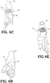
- FIGs. 6A-6E show the implant 20 disposed in respective openings of the foot and ankle bones.
- inserting the implant 20 includes positioning the implant 20 adjacent the boney structure, aligning the web structure 22 with a complementary portion of the boney structure, or advancing a contact surface toward the boney structure such that at least the web structure 22 is in contact or near contact with the boney structure.
- the implant 20 may be advanced until the contact surface is in contact or near contact with the boney structure, such that at least portion or substantially all of the web structure 22 is disposed in the boney structure.
- the implant 20 then may, or may not be, fixed in place.
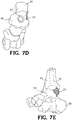
- an intramedullary nail 32 is inserted into the heel and through the passage 30 in the web structure 22 of the implant 20.
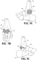
- the nail 32 is driven into the end of the tibia 36 for fusing the foot and ankle joint 34 ( FIGs. 7A-7E ).
- a tab 40 integral with the web structure 22 may be included on the implant 20.
- the tab 40 may be secured to adjacent bone with staples, screws, plates, or other means of fixation.
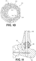
- FIG. 11 shows openings in the intramedullary nail 32 for receiving at least one screw passing through another part of the foot and ankle joint.
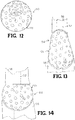
- FIGs. 13 and 14 schematically show the implants 44, 54 having an aspherical side and an egg-shape implant contacting adjacent bony structure 56.
- the implants 44, 54 are intended to be disposed between the adjacent bony structures interfacing with bone structure of a foot and ankle joint.
- the top of the implants 44, 54 may couple to a portion of the first bony structure 56 disposed above the implants and the bottom contact faces 28 may couple to the second bony structure disposed below implants 44, 54.
- the access point to the implant site may be closed using sutures or other closure devices.
Description
- A medical implant is described and, more particularly, a medical implant for use in joint or segmental bone defects for deformity correction with or without obtaining arthrodesis.
- Implants may be used in humans or animals to support or secure one or more bones. Once implanted, the implant may provide support between the bones and bone growth may take place around and through the implant to at least partially fuse the bones for longterm support.
Documents EP 1 800 627 A2 andUS 5,281,226 A disclose implants for replacing a portion of a tubular bone, the implants comprising a porous rigid component and an intramedullary nail. - There is a need for an improved medical implant for use in body areas, such as bones of the foot and ankle.
- An implant according to
claim 1 is provided for use in an ankle joint between reconditioned end surfaces established on a distal end of an upper tibia bone and an opposing lower talus bone. The implant comprises a substantially porous rigid component adapted to be anchored against the upper tibia reconditioned end surface and the lower talus reconditioned end surface. The component defining an opening therethrough. An intramedullary nail is configured to pass through the opening in the component when the nail is driven through the talus and into the tibia The component presents at least one convex surface adapted to be disposed against the reconditioned ends of the tibia and the talus. - For a more complete understanding of the bone implant, reference should now be had to the embodiments shown in the accompanying drawings and described below. In the drawings:
-
FIG. 1 is a top plan view of an embodiment of a joint or segmental bone implant. -
FIG. 2 is a top perspective view of the bone implant as shown inFIG. 1 . -
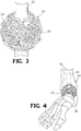
FIG. 3 is a perspective view of the bone implant as shown inFIG. 1 receiving a portion of an intramedullary nail. -
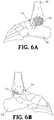
FIG. 4 is a perspective view of the bone implant as shown inFIG. 1 positioned in a foot and ankle joint. -
FIG. 5 is an exploded perspective view of the bone implant and the foot and ankle joint as shown inFIG. 4 . -
FIG. 6A is a side elevation view of the bone implant as shown inFIG. 1 positioned in a foot and ankle joint. -
FIG. 6B is an opposite side elevation view of the bone implant positioned in a foot and ankle joint as shown inFIG. 6A . -
FIG. 6C is a rear perspective view of the bone implant positioned in a foot and ankle joint as shown inFIG. 6A . -
FIG. 6D is a front perspective view of the bone implant shown in phantom positioned in a foot and ankle joint as shown inFIG. 6A . -
FIG. 6E is a top perspective view of the bone implant positioned in a foot and ankle joint as shown inFIG. 6A . -
FIG. 7A is a side elevation view of the bone implant as shown inFIG. 1 positioned in a foot and ankle joint and a portion of an intramedullary nail shown in phantom. -
FIG. 7B is a rear perspective view of the bone implant positioned in a foot and ankle joint as shown inFIG. 7A . -
FIG. 7C is an opposite side elevation view of the bone implant positioned in a foot and ankle joint as shown inFIG. 7A . -
FIG. 7D is a top plan view of the bone implant positioned in a foot and ankle joint as shown inFIG. 7A . -
FIG. 7E is an up-close view of the bone implant positioned in a foot and ankle joint as shown inFIG. 7A . -
FIG. 8 is a perspective view of another embodiment of a bone implant positioned in a foot and ankle joint and including a fixation device. -
FIG. 9 is an elevation view of a third embodiment of a bone implant having a planar surface to accommodate a plate or other device. -
FIG. 10 is an elevation view of a fourth embodiment of a bone implant positioned in a foot and ankle joint. -
FIG. 11 is a perspective view of fifth embodiment of a bone implant for use in a foot and ankle joint. -
FIG. 12 is a perspective view of a sixth embodiment of a bone implant for use in a foot and ankle joint. -
FIG. 13 is schematic elevation view of the third embodiment of the bone implant as shown inFIG. 9 between two portions of bone. -
FIG. 14 is schematic elevation view of a seventh embodiment of a bone implant shown between two portions of bone. - Certain terminology is used herein for convenience only and is not to be taken as a limitation on the invention. For example, words such as "upper," "lower," "left," "right," "horizontal," "vertical," "upward," and "downward" merely describe the configuration shown in the FIGs. Indeed, the components may be oriented in any direction and the terminology, therefore, should be understood as encompassing such variations unless specified otherwise.
- Referring now to
FIGs. 1 and 2 , there is shown an embodiment of a medical joint or segmental bone implant for deformity correction and generally designated at 20. Theimplant 20 comprises aporous web structure 22 configured to interface with human bone tissue. Theweb structure 22 extends throughout theimplant 20 to provide support. Theweb structure 22 disperses the stress of compressive forces throughout implant 20, wherein theimplant 20 is supported against tensile, compressive, and shear forces. Theweb structure 22 can be further employed to receive and distribute throughout theimplant 20 loading forces of the surrounding tissue. Theweb structure 22 may also reinforce theimplant 20 along multiple planes. - In one embodiment, the
web structure 22 is formed with interconnected triangular-shaped building blocks. The result is aweb structure 22 formed from a pattern of triangularly-shaped geometrical building blocks. The triangularly-shaped building blocks may form tetrahedrons that may also be used as building blocks. Other patterns from the triangles are also contemplated. Each tetrahedron may include four triangular faces in which three of the four triangles meet at each vertex. At least two of the plurality of tetrahedrons are coupled together via one or more common components connecting two respective vertices on each of the two tetrahedrons such that two tetrahedrons share a common unit to form a hexahedron. - In one embodiment, the
porous web structure 22 is configured to form a substantially spherical structure as shown inFIGs. 1 and 2 . Theimplant 20 can have a diameter of at least about 38 mm to about 40 mm. However, it is understood that the design of theimplant 20 may be sized appropriately to meet specified dimensions of the implantation site. In some embodiments, multiple implants of different sizes may be constructed and delivered in a kit. A medical health professional may choose an implant (e.g., according to a needed size) during surgery. It is understood that while the embodiment of theimplant 20 has been described with respect to a particular spherically-shaped web structure, various shapes of web structures are contemplated. For example, a portion of the spherical implant may be removed to form animplant 44 having a planar side (FIG. 9 ). In another embodiment shown inFIG. 14 , theimplant 54 may be egg-shaped (FIG. 14 ). - The
implant 20 may be formed from a biocompatible material such as a titanium alloy (e.g., y-titanium aluminides), cobalt, chromium, stainless steel, polyetheretherketone (PEEK), ceramics, or other suitable material. Theimplant 20 may be made through a rapid prototyping process (e.g., electron beam melting (EBM) process). Other processes are also possible, such as injection molding, casting, sintering, selective laser sintering (SLS), direct metal laser sintering (DMLS), etc). SLS may include laser-sintering of high-performance polymers such as that provided by EOS of North America, Inc., headquartered in Novi, Michigan, U.S.A. High-performance polymers may include various forms of PEEK (e.g., HP3 having a tensile strength of up to about 95 mega Pascal (MPa) and a Young's modulus of up to about 4400 MPa and continuous operating temperature between about 180 °C (356 °F) and 260 °C (500 °F)). Other materials may include PA 12 andPA 1 1 provided by EOS of North America, Inc. Multiple parts may be cast or injection molded and joined together (e.g., through welding, melting, etc.). For example,individual components 24 forming theimplant 20 may be generated separately (e.g., by casting, injection molding, etc.) and welded together to form theimplant 20. Theporous web structure 22 may be made according to the disclosure of International Application No.PCT/US2012/045717, filed July 6, 2012 , and published January 10, 2013, as International Publication No.WO 2013/006778 A2 . - In another embodiment shown in
FIG. 12 and generally designated at 50, theweb structure 22 of theimplant 50 may be formed from a generally porous material havingrandom openings 45. - The
implant top face 26 and an opposed bottom face 28 wherein at least a portion of thetop face 26 and the bottom face 28 are generally parallel to one another. In use, the top and bottom faces 26, 28 are configured to be disposed in contact, or near contact, of an adjacent bony structure for contacting the bony structure during use to adhere or couple with the adjacent structure when implanted. As depicted, for example, theimplant top contact face 26 may couple to a portion of the first bony structure disposed aboveimplant 20 and the bottom contact face 28 may couple to the second bony structure disposed belowimplant 20. - The
web structure 22 defines openings configured to define open volume to enable bone growth through the openings of theweb structure 22, thereby enhancing coupling of theimplant 20 to the adjacent bony structure. At least a portion of theweb structure 22 is in contact, or near contact, with the adjacent bony structure, thereby enabling bone growth to extend into or through at least a portion of open volume of theweb structure 22 such that the bone growth interlocks with theweb structure 22 of theimplant 20. The interlocking of the bone growth and theweb structure 22 may rigidly fix theimplant 20 in a fixed location relative to the bony structure. For example, aweb structure 22 may define an open space for bone growth therethrough, thereby enabling bone through growth to interlock the bone structure and theweb structure 22 with one another to couple theimplant 20 to the bony structure at or near the contact surface. Such interlocking bone through growth may inhibit movement between theimplant 20 and the bony structure, which could otherwise lead to loosening, migration, subsidence, or dislodging of theimplant 20 from the intended position. - The
web structure 22 of theimplant 20 may also provide surface area for bone graft fusion. For example, the voids in theweb structure 22 of theimplant 20 may be filled with, or surfaces of theweb structure 22 may be coated with, bone grafting material, a biologic, growth factor or the like. Theweb structure 22 extending throughout theimplant 20 may add additional surface area on the surface of thecomponents 24 to fuse to the bone graft material and prevent the bone graft material from loosening or migrating from theimplant 20. In some embodiments, theweb structure 22 may also support and facilitate bone in-growth. For example, adjacent bone in an ankle joint may grow over at least a portion of thecomponents 24 of theimplant 22. The bone growth and engagement between the bone growth and theimplant 20 may further stabilize the implant. In some embodiments, the surfaces of theimplant 20 may be formed with a rough surface to assist in bone in-growth adhesion. - At least a portion of the open volume of the
web structure 22 of theimplant 20 may be filled with bone growth material. For example, cancellous bone may be packed into the openings internally of theimplant 20. In some embodiments, at least a portion of the surfaces ofimplant 20 may be coated or treated with a material intend to promote bone growth or bone adhesion or an antimicrobial agent to prevent infections. For example, in some embodiments, the surface of theweb structure 22 may be coated with a biologic or a bone growth factor. For example, the biologic or growth factor may be physically secured to theweb structure 22 in a central portion of theimplant 20 provided there is the physical attachment of the biologic or growth factor. The biologic may include a coating, such as hydroxyapatite, bone morphaginic protein (BMP), insulin-like growth factors I and II, transforming growth factor-beta, acidic and basic fibroblast growth factor, platelet-derived growth factor, or similar bone growth stimulant that facilitates good biological fixation between the bone growth and a surface of theimplant 20. The bone growth factor may include a naturally occurring substance capable of stimulating cellular growth, proliferation and cellular differentiation (e.g., a protein or steroid hormone). - As shown in the
FIGs. 1 and 2 , the center portion of thespherical web structure 22 defines acylindrical passage 30. Thecentral passage 30 is configured to receive an intramedullary nail extending therethrough (FIG. 3 ). - In the embodiment of the
implant 44 shown inFIG. 9 , the planar or aspherical portion of theimplant 44 accommodates aplate 42 or the like to facilitate attaching the combinedporous web structure 45 and theplate 42 to bone using screws 48. For example, where an implant is implanted adjacent to a bony structure, one or more structures may be disposed on or extend from a surface (e.g., an interface plate) of the implant that is intended to contact, and at least partially adhere to, the bony structure during use. - A method is disclosed that includes the steps of providing an opening in a foot or
ankle 34 of a human, and installing into the opening theimplant ankle 34 to the level of proposed implantation. Next, a bone bed can be prepared from the adjacent bony structure either by using a spherical reaming device or using a saw and osteotomes. The bone bed may be formed in either a joint or within a single bone. Bone graft material may be packed in the bone bed or within theporous web structure 22 of theimplant 20. Theimplant 20 is then inserted into the bone bed. Theimplant 20 may be incorporated into the end surfaces established between anupper tibia bone 36 and an opposite andlower talus bone 38. The shape of at least a portion of theimplant 20 allows the bone or the joint surface on either side of theimplant 20 to be placed in a preferred position, for example, to correct a deformity.FIGs. 6A-6E show theimplant 20 disposed in respective openings of the foot and ankle bones. - Optionally, inserting the
implant 20 includes positioning theimplant 20 adjacent the boney structure, aligning theweb structure 22 with a complementary portion of the boney structure, or advancing a contact surface toward the boney structure such that at least theweb structure 22 is in contact or near contact with the boney structure. Optionally, theimplant 20 may be advanced until the contact surface is in contact or near contact with the boney structure, such that at least portion or substantially all of theweb structure 22 is disposed in the boney structure. - The
implant 20 then may, or may not be, fixed in place. In one embodiment, anintramedullary nail 32 is inserted into the heel and through thepassage 30 in theweb structure 22 of theimplant 20. Thenail 32 is driven into the end of thetibia 36 for fusing the foot and ankle joint 34 (FIGs. 7A-7E ). In an embodiment shown inFIG. 8 , atab 40 integral with theweb structure 22 may be included on theimplant 20. Thetab 40 may be secured to adjacent bone with staples, screws, plates, or other means of fixation.FIG. 11 shows openings in theintramedullary nail 32 for receiving at least one screw passing through another part of the foot and ankle joint. -
FIGs. 13 and 14 schematically show theimplants bony structure 56. As depicted, theimplants implants bony structure 56 disposed above the implants and the bottom contact faces 28 may couple to the second bony structure disposed belowimplants - Once the implant is positioned in the foot and ankle joint 34, the access point to the implant site may be closed using sutures or other closure devices.
- Although the bone implant has been shown and described in considerable detail with respect to only a few exemplary embodiments thereof, it should be understood by those skilled in the art that I do not intend to limit the invention to the embodiments since various modifications, omissions and additions may be made to the disclosed embodiments without materially departing from the novel teachings and advantages, particularly in light of the foregoing teachings. Accordingly, I intend to cover all such modifications, omission, additions and equivalents as are included within the scope of the bone implant as defined by the following claims.
Claims (6)
- An implant for use in an ankle joint between reconditioned end surfaces established on a distal end of an upper tibia bone and an opposing lower talus bone, the implant comprising:a substantially porous rigid component (20) adapted to be anchored against the upper tibia reconditioned end surface and the lower talus reconditioned end surface, the component defining an opening (30) therethrough; andan intramedullary nail (32) configured to pass through the opening in the component when the nail is driven through the talus and into the tibia, wherein the component presents at least one convex surface adapted to be disposed against the reconditioned ends of the tibia and the talus.
- The implant as recited in claim 1, wherein the component is a spherical shape.
- The implant as recited in claim 1, wherein the component has a generally spherical shape wherein a portion of a sphere is removed to present a planar surface adapted to be disposed against the reconditioned ends of the tibia and the talus.
- The implant as recited in claim 1, wherein the component has a generally spherical shape wherein a portion of a sphere is removed to present a planar surface, further comprising a planar plate member (42) configured to be secured to the planar surface of the component, the plate member adapted to be fastened to the tibia or the talus.
- The implant as recited in claim 2, further comprising a tab extending from the component, the tab adapted to be fastened to the tibia or the talus for further securing the component between the end surfaces.
- The implant as recited in any one of the preceding claims, wherein the intramedullary nail defines a plurality of longitudinally spaced openings, and further comprising a fastener adapted to pass through the talus or the tibia and at least one opening in the nail for further securing the component.
Applications Claiming Priority (2)
| Application Number | Priority Date | Filing Date | Title |
|---|---|---|---|
| US201562165376P | 2015-05-22 | 2015-05-22 | |
| PCT/US2016/033835 WO2016191393A1 (en) | 2015-05-22 | 2016-05-23 | Joint or segmental bone implant for deformity correction |
Publications (2)
| Publication Number | Publication Date |
|---|---|
| EP3297553A1 EP3297553A1 (en) | 2018-03-28 |
| EP3297553B1 true EP3297553B1 (en) | 2020-10-14 |
Family
ID=56131615
Family Applications (1)
| Application Number | Title | Priority Date | Filing Date |
|---|---|---|---|
| EP16729417.2A Active EP3297553B1 (en) | 2015-05-22 | 2016-05-23 | Joint or segmental bone implant for deformity correction |
Country Status (7)
| Country | Link |
|---|---|
| US (5) | US10045854B2 (en) |
| EP (1) | EP3297553B1 (en) |
| JP (1) | JP2018519134A (en) |
| CN (1) | CN107835669A (en) |
| AU (1) | AU2016267051A1 (en) |
| CA (1) | CA2986752A1 (en) |
| WO (1) | WO2016191393A1 (en) |
Families Citing this family (12)
| Publication number | Priority date | Publication date | Assignee | Title |
|---|---|---|---|---|
| US8728387B2 (en) * | 2005-12-06 | 2014-05-20 | Howmedica Osteonics Corp. | Laser-produced porous surface |
| WO2015017074A1 (en) * | 2013-07-02 | 2015-02-05 | Cmarr Enterprises | Curved tibiotalar fusion nail and method of use |
| US10610368B2 (en) * | 2018-05-26 | 2020-04-07 | Acumed Llc | Ankle fusion system with expandable spacer |
| EP3297553B1 (en) | 2015-05-22 | 2020-10-14 | Stryker European Operations Limited | Joint or segmental bone implant for deformity correction |
| US11547456B2 (en) * | 2017-01-12 | 2023-01-10 | Dt Medtech, Llc | Internal ankle fixation systems, foot securement and jig devices, and related methods |
| CN110678150B (en) * | 2017-02-21 | 2021-11-05 | 拜欧米特制造有限责任公司 | Implant for bridging a bone defect |
| EP3582725B1 (en) * | 2017-06-13 | 2023-06-21 | Wright Medical Technology, Inc. | Calcaneal prosthesis |
| US20190167433A1 (en) * | 2017-12-04 | 2019-06-06 | Duke University | Orthopedic implant for sustained drug release |
| WO2019119156A1 (en) * | 2017-12-22 | 2019-06-27 | Pure Technologies Ltd. | Surround for pipeline inspection equipment |
| US11147679B2 (en) * | 2018-02-05 | 2021-10-19 | Paragon Advanced Technologies, Inc. | Bone fixation device |
| CA3159552A1 (en) * | 2019-10-30 | 2021-05-06 | 4Web, Inc. | Programmable intramedullary implants and methods of using programmable intramedullary implants to repair bone structures |
| WO2023015196A1 (en) * | 2021-08-02 | 2023-02-09 | Paragon 28, Inc. | Implants, instruments, systems, and methods of using |
Family Cites Families (91)
| Publication number | Priority date | Publication date | Assignee | Title |
|---|---|---|---|---|
| GB595628A (en) | 1944-06-28 | 1947-12-11 | George Samuel Adams | Improvements in clothes drying and airing devices |
| GB190118231A (en) | 1901-09-12 | 1901-11-30 | Samuel Adams White | An Improved Dish for use in Dressing Boots and Shoes |
| FR373990A (en) | 1906-04-29 | 1907-05-31 | Edwin Trueman | Device for braking or locking the wheels of wagons, mine tanks, etc. |
| GB972282A (en) | 1959-10-06 | 1964-10-14 | Samuel Adams | Device for production of electrons for high frequency purposes |
| DE3637314A1 (en) | 1986-11-03 | 1988-05-11 | Lutz Biedermann | SPACE HOLDER IMPLANT |
| US5281226A (en) * | 1989-03-31 | 1994-01-25 | Davydov Anatoly B | Missing portion of a tubular bone |
| US4936848A (en) * | 1989-09-22 | 1990-06-26 | Bagby George W | Implant for vertebrae |
| DE19504867C1 (en) | 1995-02-14 | 1996-02-29 | Harms Juergen | Position retainer for spine |
| US5609367A (en) | 1995-12-01 | 1997-03-11 | Alliedsignal Inc. | Adjustable three-point restraint seat belt system for children and adults |
| DE29616778U1 (en) | 1996-09-26 | 1998-01-29 | Howmedica Gmbh | Vertebral body placeholder |
| US6585770B1 (en) | 1997-06-02 | 2003-07-01 | Sdgi Holdings, Inc. | Devices for supporting bony structures |
| ATE247442T1 (en) | 1997-09-30 | 2003-09-15 | Ct Pulse Orthopedics Ltd | TUBULAR SUPPORT BODY FOR BRIDGING TWO VERTEBRATES |
| US6086613A (en) | 1997-12-23 | 2000-07-11 | Depuy Acromed, Inc. | Spacer assembly for use in spinal surgeries |
| WO1999033641A1 (en) | 1997-12-24 | 1999-07-08 | Molecular Geodesics, Inc. | Foam scaffold materials |
| DE19804765C2 (en) | 1998-02-06 | 2000-09-28 | Biedermann Motech Gmbh | Placeholder with adjustable axial length |
| US6206924B1 (en) | 1999-10-20 | 2001-03-27 | Interpore Cross Internat | Three-dimensional geometric bio-compatible porous engineered structure for use as a bone mass replacement or fusion augmentation device |
| DE60025532T2 (en) | 1999-10-22 | 2006-09-14 | Reiley, Mark A., Peidmont | ANKLE PROSTHESIS |
| US6673116B2 (en) | 1999-10-22 | 2004-01-06 | Mark A. Reiley | Intramedullary guidance systems and methods for installing ankle replacement prostheses |
| JP2003517875A (en) * | 1999-12-17 | 2003-06-03 | カーティフィシャル・アクティーゼルスカブ | Prosthetic device |
| US6579293B1 (en) | 2000-08-02 | 2003-06-17 | Rama E. Chandran | Intramedullary rod with interlocking oblique screw for tibio-calcaneal arthrodesis |
| AU2002213404A1 (en) | 2000-10-24 | 2002-05-06 | Howmedica Osteonics Corp. | Barrel-shaped apparatus for fusing adjacent bone structure |
| US6931812B1 (en) | 2000-12-22 | 2005-08-23 | Stephen Leon Lipscomb | Web structure and method for making the same |
| EP1345888A1 (en) | 2000-12-22 | 2003-09-24 | Bayer Aktiengesellschaft | Method for the production of 1,5-naphthalenediamine |
| WO2003000480A1 (en) | 2001-06-22 | 2003-01-03 | The Regents Of The University Of Michigan | Methods of designing and fabricating molds |
| GB0129176D0 (en) | 2001-12-06 | 2002-01-23 | Dca Design Int Ltd | Improvements in and realting to a medicament cartridge assembly |
| TWI231755B (en) | 2002-10-07 | 2005-05-01 | Conformis Inc | An interpositional articular implant and the method for making the same |
| EP1418013B1 (en) | 2002-11-08 | 2005-01-19 | Howmedica Osteonics Corp. | Laser-produced porous surface |
| US20060147332A1 (en) | 2004-12-30 | 2006-07-06 | Howmedica Osteonics Corp. | Laser-produced porous structure |
| EP1638459A2 (en) | 2003-06-11 | 2006-03-29 | Case Western Reserve University | Computer-aided-design of skeletal implants |
| US9364330B2 (en) | 2003-06-25 | 2016-06-14 | Biedermann Technologies Gmbh & Co. Kg | Tissue integration design for seamless implant fixation |
| US8062365B2 (en) | 2003-08-04 | 2011-11-22 | Warsaw Orthopedic, Inc. | Bone supporting devices with bio-absorbable end members |
| WO2005051233A2 (en) | 2003-11-21 | 2005-06-09 | William Marsh Rice University | Computer-aided tissue engineering of a biological body |
| US7410488B2 (en) | 2005-02-18 | 2008-08-12 | Smith & Nephew, Inc. | Hindfoot nail |
| US8292967B2 (en) | 2005-04-21 | 2012-10-23 | Biomet Manufacturing Corp. | Method and apparatus for use of porous implants |
| US9005944B2 (en) | 2005-12-14 | 2015-04-14 | The Invention Science Fund I, Llc | Bone cell delivery device |
| US20110172826A1 (en) | 2005-12-14 | 2011-07-14 | Amodei Dario G | Device including altered microorganisms, and methods and systems of use |
| US8367384B2 (en) | 2005-12-14 | 2013-02-05 | The Invention Science Fund I, Llc | Bone semi-permeable device |
| US8198080B2 (en) | 2005-12-14 | 2012-06-12 | The Invention Science Fund I, Llc | Bone delivery device |
| US8278094B2 (en) | 2005-12-14 | 2012-10-02 | The Invention Science Fund I, Llc | Bone semi-permeable device |
| US8734823B2 (en) | 2005-12-14 | 2014-05-27 | The Invention Science Fund I, Llc | Device including altered microorganisms, and methods and systems of use |
| US8682619B2 (en) | 2005-12-14 | 2014-03-25 | The Invention Science Fund I, Llc | Device including altered microorganisms, and methods and systems of use |
| US8900865B2 (en) | 2005-12-14 | 2014-12-02 | The Invention Science Fund I, Llc | Blood brain barrier device |
| US9061075B2 (en) | 2005-12-14 | 2015-06-23 | The Invention Science Fund I, Llc | Bone delivery device |
| US8354258B2 (en) | 2005-12-14 | 2013-01-15 | The Invention Science Fund I, Llc | Diatom device |
| DE102005061932A1 (en) | 2005-12-23 | 2007-07-05 | Biedermann Motech Gmbh | Placeholder for implantation to the human vertebrae has three tubular bodies having different lengths and diameters that are inserted and connected to each other by pins so that they project over the edges of the next larger tubular body |
| WO2008022206A2 (en) | 2006-08-15 | 2008-02-21 | Motionback Llc | Spinal implant |
| US9890827B2 (en) | 2007-05-10 | 2018-02-13 | Hrl Laboratories, Llc | Energy absorbing truss structures for mitigation of injuries from blasts and impacts |
| CN101772357A (en) | 2007-06-07 | 2010-07-07 | 史密夫和内修有限公司 | Reticulated particle porous coating for medical implant use |
| US20090177240A1 (en) | 2007-10-16 | 2009-07-09 | Perez Edward A | Long bone fixation system and methods |
| CN201164511Y (en) | 2008-03-03 | 2008-12-17 | 曼德卡姆有限公司 | Artificial hip joint acetabulum exterior lining |
| DE102008012731A1 (en) | 2008-03-05 | 2009-09-24 | Uhde Gmbh | Device for discharging fine-grained or dust-like solids from a container |
| CN201200499Y (en) | 2008-05-19 | 2009-03-04 | 曼德卡姆有限公司 | Grid-shaped metal implantation body of orthopaedics |
| GB0809721D0 (en) | 2008-05-28 | 2008-07-02 | Univ Bath | Improvements in or relating to joints and/or implants |
| CA2746505C (en) | 2008-12-18 | 2017-06-13 | 4-Web Spine, Inc. | Truss implant |
| US8808303B2 (en) | 2009-02-24 | 2014-08-19 | Microport Orthopedics Holdings Inc. | Orthopedic surgical guide |
| DE102009054605B8 (en) | 2009-12-14 | 2011-12-15 | Fraunhofer-Gesellschaft zur Förderung der angewandten Forschung e.V. | Open-cell titanium metal foams |
| US20110200478A1 (en) | 2010-02-14 | 2011-08-18 | Romain Louis Billiet | Inorganic structures with controlled open cell porosity and articles made therefrom |
| EP2544608A4 (en) | 2010-03-08 | 2017-02-22 | Conventus Orthopaedics, Inc. | Apparatus and methods for securing a bone implant |
| WO2011123110A1 (en) | 2010-03-30 | 2011-10-06 | Daniel Sunho Oh | Method of preparing ceramic/polymer composite scaffolds with bioactive molecules for hard tissue regeneration |
| US8532806B1 (en) | 2010-06-07 | 2013-09-10 | Marcos V. Masson | Process for manufacture of joint implants |
| US20110313532A1 (en) | 2010-06-18 | 2011-12-22 | Jessee Hunt | Bone implant interface system and method |
| US9161796B2 (en) * | 2010-12-18 | 2015-10-20 | The Brigham And Women's Hospital, Inc. | Medical devices for use during ankle fusion surgery |
| US8545572B2 (en) | 2011-01-21 | 2013-10-01 | Trilliant Surgical, Ltd. | Subtalar implant |
| CN103476363B (en) | 2011-02-15 | 2017-06-30 | 康复米斯公司 | Operation and the instrument of change and/or asymmetry are dissected in improved suitable patient's type joint implant and treatment, assessment, correction, modification and/or adaptation |
| WO2013006778A2 (en) | 2011-07-07 | 2013-01-10 | 4-Web, Inc. | Foot and ankle implant system and method |
| US20130030529A1 (en) | 2011-07-29 | 2013-01-31 | Jessee Hunt | Implant interface system and method |
| US8979937B2 (en) | 2011-09-27 | 2015-03-17 | Linares Medical Devices, Llc | Implantable ankle joint assembly with spherical inter-support |
| AU2012332092A1 (en) | 2011-11-03 | 2014-05-15 | 4-Web, Inc. | Method of length preservation during bone repair |
| US8485820B1 (en) | 2011-12-22 | 2013-07-16 | Mohamed Ikbal Ali | Devices and methods for enhancing bone growth |
| US9364896B2 (en) | 2012-02-07 | 2016-06-14 | Medical Modeling Inc. | Fabrication of hybrid solid-porous medical implantable devices with electron beam melting technology |
| JP2015511838A (en) | 2012-02-08 | 2015-04-23 | フォー−ウェブ・インコーポレイテッド | Prosthetic implant for acetabular joint and method of using the same |
| US20130218278A1 (en) | 2012-02-21 | 2013-08-22 | Steve Wolfe | Device and method for performing spinal interbody fusion |
| JP6310922B2 (en) | 2012-09-25 | 2018-04-11 | フォー−ウェブ・インコーポレイテッド | Programmable graft and method of using a programmable graft to repair bone structure |
| US9125695B2 (en) * | 2012-10-18 | 2015-09-08 | Bespa, Inc. | Ankle fusion nail apparatus and method |
| CN102940542B (en) * | 2012-10-23 | 2015-05-20 | 华中科技大学 | Artificial limb ankle joint with four passive degrees of freedom |
| CN203001181U (en) * | 2012-11-14 | 2013-06-19 | 黄国富 | Buffer type artificial ankle joint |
| US10123862B2 (en) | 2013-03-14 | 2018-11-13 | Ethicon, Inc. | Randomly uniform three dimensional tissue scaffold of absorbable and non-absorbable materials |
| US9352071B2 (en) | 2013-03-14 | 2016-05-31 | Ethicon, Inc. | Method of forming an implantable device |
| US20140288650A1 (en) | 2013-03-15 | 2014-09-25 | 4Web, Inc. | Motion preservation implant and methods |
| US9724203B2 (en) | 2013-03-15 | 2017-08-08 | Smed-Ta/Td, Llc | Porous tissue ingrowth structure |
| WO2014145529A2 (en) | 2013-03-15 | 2014-09-18 | 4-Web, Inc. | Traumatic bone fracture repair systems and methods |
| US10166033B2 (en) | 2014-09-18 | 2019-01-01 | Si-Bone Inc. | Implants for bone fixation or fusion |
| US9452056B2 (en) * | 2014-09-29 | 2016-09-27 | Biomet C.V. | Implants for fixation of the distal tibia |
| US10070962B1 (en) | 2015-02-13 | 2018-09-11 | Nextstep Arthropedix, LLC | Medical implants having desired surface features and methods of manufacturing |
| EP3297553B1 (en) | 2015-05-22 | 2020-10-14 | Stryker European Operations Limited | Joint or segmental bone implant for deformity correction |
| WO2017192632A1 (en) | 2016-05-03 | 2017-11-09 | Additive Orthopaedics, LLC | Bone fixation device and method of use |
| WO2017210695A1 (en) | 2016-06-03 | 2017-12-07 | Additive Orthopaedics, LLC | Bone fixation devices |
| WO2018023131A1 (en) | 2016-07-29 | 2018-02-01 | Additive Orthopaedics, LLC | Bone fixation device and method of use |
| JP6822043B2 (en) | 2016-09-28 | 2021-01-27 | ブラザー工業株式会社 | Printing equipment |
| US10064726B1 (en) | 2017-04-18 | 2018-09-04 | Warsaw Orthopedic, Inc. | 3D printing of mesh implants for bone delivery |
| US10182832B1 (en) | 2017-08-24 | 2019-01-22 | Limacorporate S.P.A. | Ankle arthroplasty systems and methods |
-
2016
- 2016-05-23 EP EP16729417.2A patent/EP3297553B1/en active Active
- 2016-05-23 JP JP2018512843A patent/JP2018519134A/en active Pending
- 2016-05-23 CN CN201680040821.5A patent/CN107835669A/en active Pending
- 2016-05-23 AU AU2016267051A patent/AU2016267051A1/en not_active Abandoned
- 2016-05-23 US US15/162,525 patent/US10045854B2/en active Active
- 2016-05-23 CA CA2986752A patent/CA2986752A1/en not_active Abandoned
- 2016-05-23 WO PCT/US2016/033835 patent/WO2016191393A1/en active Application Filing
-
2017
- 2017-03-02 US US15/447,227 patent/US10517737B2/en active Active
-
2018
- 2018-08-13 US US16/102,107 patent/US11395747B2/en active Active
-
2019
- 2019-12-30 US US16/729,739 patent/US11759332B2/en active Active
-
2023
- 2023-08-14 US US18/233,598 patent/US20230380987A1/en active Pending
Non-Patent Citations (1)
| Title |
|---|
| None * |
Also Published As
| Publication number | Publication date |
|---|---|
| US11395747B2 (en) | 2022-07-26 |
| JP2018519134A (en) | 2018-07-19 |
| US10517737B2 (en) | 2019-12-31 |
| US20160338842A1 (en) | 2016-11-24 |
| US20170172752A1 (en) | 2017-06-22 |
| US10045854B2 (en) | 2018-08-14 |
| CN107835669A (en) | 2018-03-23 |
| CA2986752A1 (en) | 2016-12-01 |
| US20200129303A1 (en) | 2020-04-30 |
| US11759332B2 (en) | 2023-09-19 |
| EP3297553A1 (en) | 2018-03-28 |
| AU2016267051A1 (en) | 2017-12-14 |
| US20230380987A1 (en) | 2023-11-30 |
| WO2016191393A1 (en) | 2016-12-01 |
| US20180360611A1 (en) | 2018-12-20 |
Similar Documents
| Publication | Publication Date | Title |
|---|---|---|
| US11395747B2 (en) | Joint or segmental bone implant for deformity correction | |
| US10828111B2 (en) | Implant placement planning | |
| US10213309B2 (en) | Tissue integration design for seamless implant fixation | |
| JP5885355B2 (en) | Implant components and methods | |
| CA2911880C (en) | Traumatic bone fracture repair systems and methods | |
| JP6177788B2 (en) | How to preserve length during bone repair | |
| JP2022000292A (en) | Implant with multi-layer bone interfacing lattice | |
| US20070185582A1 (en) | Methods and Devices for Resurfacing the Wrist Joint | |
| JP2013524981A (en) | Prosthesis | |
| AU2004275762A1 (en) | Reinforced fusion implant | |
| CN110312479B (en) | Stepped nail for fracture fixation |
Legal Events
| Date | Code | Title | Description |
|---|---|---|---|
| STAA | Information on the status of an ep patent application or granted ep patent |
Free format text: STATUS: THE INTERNATIONAL PUBLICATION HAS BEEN MADE |
|
| PUAI | Public reference made under article 153(3) epc to a published international application that has entered the european phase |
Free format text: ORIGINAL CODE: 0009012 |
|
| STAA | Information on the status of an ep patent application or granted ep patent |
Free format text: STATUS: REQUEST FOR EXAMINATION WAS MADE |
|
| 17P | Request for examination filed |
Effective date: 20171122 |
|
| AK | Designated contracting states |
Kind code of ref document: A1 Designated state(s): AL AT BE BG CH CY CZ DE DK EE ES FI FR GB GR HR HU IE IS IT LI LT LU LV MC MK MT NL NO PL PT RO RS SE SI SK SM TR |
|
| AX | Request for extension of the european patent |
Extension state: BA ME |
|
| DAV | Request for validation of the european patent (deleted) | ||
| DAX | Request for extension of the european patent (deleted) | ||
| RAP1 | Party data changed (applicant data changed or rights of an application transferred) |
Owner name: STRYKER EUROPEAN OPERATIONS LIMITED |
|
| GRAP | Despatch of communication of intention to grant a patent |
Free format text: ORIGINAL CODE: EPIDOSNIGR1 |
|
| STAA | Information on the status of an ep patent application or granted ep patent |
Free format text: STATUS: GRANT OF PATENT IS INTENDED |
|
| INTG | Intention to grant announced |
Effective date: 20200506 |
|
| GRAS | Grant fee paid |
Free format text: ORIGINAL CODE: EPIDOSNIGR3 |
|
| GRAA | (expected) grant |
Free format text: ORIGINAL CODE: 0009210 |
|
| STAA | Information on the status of an ep patent application or granted ep patent |
Free format text: STATUS: THE PATENT HAS BEEN GRANTED |
|
| AK | Designated contracting states |
Kind code of ref document: B1 Designated state(s): AL AT BE BG CH CY CZ DE DK EE ES FI FR GB GR HR HU IE IS IT LI LT LU LV MC MK MT NL NO PL PT RO RS SE SI SK SM TR |
|
| REG | Reference to a national code |
Ref country code: GB Ref legal event code: FG4D |
|
| REG | Reference to a national code |
Ref country code: AT Ref legal event code: REF Ref document number: 1322805 Country of ref document: AT Kind code of ref document: T Effective date: 20201015 Ref country code: CH Ref legal event code: EP |
|
| REG | Reference to a national code |
Ref country code: DE Ref legal event code: R096 Ref document number: 602016045810 Country of ref document: DE |
|
| REG | Reference to a national code |
Ref country code: IE Ref legal event code: FG4D |
|
| REG | Reference to a national code |
Ref country code: AT Ref legal event code: MK05 Ref document number: 1322805 Country of ref document: AT Kind code of ref document: T Effective date: 20201014 |
|
| REG | Reference to a national code |
Ref country code: NL Ref legal event code: MP Effective date: 20201014 |
|
| PG25 | Lapsed in a contracting state [announced via postgrant information from national office to epo] |
Ref country code: PT Free format text: LAPSE BECAUSE OF FAILURE TO SUBMIT A TRANSLATION OF THE DESCRIPTION OR TO PAY THE FEE WITHIN THE PRESCRIBED TIME-LIMIT Effective date: 20210215 Ref country code: RS Free format text: LAPSE BECAUSE OF FAILURE TO SUBMIT A TRANSLATION OF THE DESCRIPTION OR TO PAY THE FEE WITHIN THE PRESCRIBED TIME-LIMIT Effective date: 20201014 Ref country code: NO Free format text: LAPSE BECAUSE OF FAILURE TO SUBMIT A TRANSLATION OF THE DESCRIPTION OR TO PAY THE FEE WITHIN THE PRESCRIBED TIME-LIMIT Effective date: 20210114 Ref country code: NL Free format text: LAPSE BECAUSE OF FAILURE TO SUBMIT A TRANSLATION OF THE DESCRIPTION OR TO PAY THE FEE WITHIN THE PRESCRIBED TIME-LIMIT Effective date: 20201014 Ref country code: FI Free format text: LAPSE BECAUSE OF FAILURE TO SUBMIT A TRANSLATION OF THE DESCRIPTION OR TO PAY THE FEE WITHIN THE PRESCRIBED TIME-LIMIT Effective date: 20201014 Ref country code: GR Free format text: LAPSE BECAUSE OF FAILURE TO SUBMIT A TRANSLATION OF THE DESCRIPTION OR TO PAY THE FEE WITHIN THE PRESCRIBED TIME-LIMIT Effective date: 20210115 |
|
| REG | Reference to a national code |
Ref country code: LT Ref legal event code: MG4D |
|
| PG25 | Lapsed in a contracting state [announced via postgrant information from national office to epo] |
Ref country code: SE Free format text: LAPSE BECAUSE OF FAILURE TO SUBMIT A TRANSLATION OF THE DESCRIPTION OR TO PAY THE FEE WITHIN THE PRESCRIBED TIME-LIMIT Effective date: 20201014 Ref country code: BG Free format text: LAPSE BECAUSE OF FAILURE TO SUBMIT A TRANSLATION OF THE DESCRIPTION OR TO PAY THE FEE WITHIN THE PRESCRIBED TIME-LIMIT Effective date: 20210114 Ref country code: IS Free format text: LAPSE BECAUSE OF FAILURE TO SUBMIT A TRANSLATION OF THE DESCRIPTION OR TO PAY THE FEE WITHIN THE PRESCRIBED TIME-LIMIT Effective date: 20210214 Ref country code: PL Free format text: LAPSE BECAUSE OF FAILURE TO SUBMIT A TRANSLATION OF THE DESCRIPTION OR TO PAY THE FEE WITHIN THE PRESCRIBED TIME-LIMIT Effective date: 20201014 Ref country code: LV Free format text: LAPSE BECAUSE OF FAILURE TO SUBMIT A TRANSLATION OF THE DESCRIPTION OR TO PAY THE FEE WITHIN THE PRESCRIBED TIME-LIMIT Effective date: 20201014 Ref country code: ES Free format text: LAPSE BECAUSE OF FAILURE TO SUBMIT A TRANSLATION OF THE DESCRIPTION OR TO PAY THE FEE WITHIN THE PRESCRIBED TIME-LIMIT Effective date: 20201014 Ref country code: AT Free format text: LAPSE BECAUSE OF FAILURE TO SUBMIT A TRANSLATION OF THE DESCRIPTION OR TO PAY THE FEE WITHIN THE PRESCRIBED TIME-LIMIT Effective date: 20201014 |
|
| PG25 | Lapsed in a contracting state [announced via postgrant information from national office to epo] |
Ref country code: HR Free format text: LAPSE BECAUSE OF FAILURE TO SUBMIT A TRANSLATION OF THE DESCRIPTION OR TO PAY THE FEE WITHIN THE PRESCRIBED TIME-LIMIT Effective date: 20201014 |
|
| REG | Reference to a national code |
Ref country code: DE Ref legal event code: R097 Ref document number: 602016045810 Country of ref document: DE |
|
| PG25 | Lapsed in a contracting state [announced via postgrant information from national office to epo] |
Ref country code: SM Free format text: LAPSE BECAUSE OF FAILURE TO SUBMIT A TRANSLATION OF THE DESCRIPTION OR TO PAY THE FEE WITHIN THE PRESCRIBED TIME-LIMIT Effective date: 20201014 Ref country code: LT Free format text: LAPSE BECAUSE OF FAILURE TO SUBMIT A TRANSLATION OF THE DESCRIPTION OR TO PAY THE FEE WITHIN THE PRESCRIBED TIME-LIMIT Effective date: 20201014 Ref country code: CZ Free format text: LAPSE BECAUSE OF FAILURE TO SUBMIT A TRANSLATION OF THE DESCRIPTION OR TO PAY THE FEE WITHIN THE PRESCRIBED TIME-LIMIT Effective date: 20201014 Ref country code: EE Free format text: LAPSE BECAUSE OF FAILURE TO SUBMIT A TRANSLATION OF THE DESCRIPTION OR TO PAY THE FEE WITHIN THE PRESCRIBED TIME-LIMIT Effective date: 20201014 Ref country code: RO Free format text: LAPSE BECAUSE OF FAILURE TO SUBMIT A TRANSLATION OF THE DESCRIPTION OR TO PAY THE FEE WITHIN THE PRESCRIBED TIME-LIMIT Effective date: 20201014 Ref country code: SK Free format text: LAPSE BECAUSE OF FAILURE TO SUBMIT A TRANSLATION OF THE DESCRIPTION OR TO PAY THE FEE WITHIN THE PRESCRIBED TIME-LIMIT Effective date: 20201014 |
|
| PLBE | No opposition filed within time limit |
Free format text: ORIGINAL CODE: 0009261 |
|
| STAA | Information on the status of an ep patent application or granted ep patent |
Free format text: STATUS: NO OPPOSITION FILED WITHIN TIME LIMIT |
|
| PG25 | Lapsed in a contracting state [announced via postgrant information from national office to epo] |
Ref country code: DK Free format text: LAPSE BECAUSE OF FAILURE TO SUBMIT A TRANSLATION OF THE DESCRIPTION OR TO PAY THE FEE WITHIN THE PRESCRIBED TIME-LIMIT Effective date: 20201014 |
|
| 26N | No opposition filed |
Effective date: 20210715 |
|
| PG25 | Lapsed in a contracting state [announced via postgrant information from national office to epo] |
Ref country code: IT Free format text: LAPSE BECAUSE OF FAILURE TO SUBMIT A TRANSLATION OF THE DESCRIPTION OR TO PAY THE FEE WITHIN THE PRESCRIBED TIME-LIMIT Effective date: 20201014 Ref country code: AL Free format text: LAPSE BECAUSE OF FAILURE TO SUBMIT A TRANSLATION OF THE DESCRIPTION OR TO PAY THE FEE WITHIN THE PRESCRIBED TIME-LIMIT Effective date: 20201014 |
|
| PG25 | Lapsed in a contracting state [announced via postgrant information from national office to epo] |
Ref country code: SI Free format text: LAPSE BECAUSE OF FAILURE TO SUBMIT A TRANSLATION OF THE DESCRIPTION OR TO PAY THE FEE WITHIN THE PRESCRIBED TIME-LIMIT Effective date: 20201014 |
|
| REG | Reference to a national code |
Ref country code: CH Ref legal event code: PL |
|
| PG25 | Lapsed in a contracting state [announced via postgrant information from national office to epo] |
Ref country code: CH Free format text: LAPSE BECAUSE OF NON-PAYMENT OF DUE FEES Effective date: 20210531 Ref country code: LU Free format text: LAPSE BECAUSE OF NON-PAYMENT OF DUE FEES Effective date: 20210523 Ref country code: LI Free format text: LAPSE BECAUSE OF NON-PAYMENT OF DUE FEES Effective date: 20210531 Ref country code: MC Free format text: LAPSE BECAUSE OF FAILURE TO SUBMIT A TRANSLATION OF THE DESCRIPTION OR TO PAY THE FEE WITHIN THE PRESCRIBED TIME-LIMIT Effective date: 20201014 |
|
| REG | Reference to a national code |
Ref country code: BE Ref legal event code: MM Effective date: 20210531 |
|
| PG25 | Lapsed in a contracting state [announced via postgrant information from national office to epo] |
Ref country code: IS Free format text: LAPSE BECAUSE OF FAILURE TO SUBMIT A TRANSLATION OF THE DESCRIPTION OR TO PAY THE FEE WITHIN THE PRESCRIBED TIME-LIMIT Effective date: 20210214 |
|
| PG25 | Lapsed in a contracting state [announced via postgrant information from national office to epo] |
Ref country code: BE Free format text: LAPSE BECAUSE OF NON-PAYMENT OF DUE FEES Effective date: 20210531 |
|
| PGFP | Annual fee paid to national office [announced via postgrant information from national office to epo] |
Ref country code: IE Payment date: 20230310 Year of fee payment: 8 |
|
| PG25 | Lapsed in a contracting state [announced via postgrant information from national office to epo] |
Ref country code: HU Free format text: LAPSE BECAUSE OF FAILURE TO SUBMIT A TRANSLATION OF THE DESCRIPTION OR TO PAY THE FEE WITHIN THE PRESCRIBED TIME-LIMIT; INVALID AB INITIO Effective date: 20160523 |
|
| PGFP | Annual fee paid to national office [announced via postgrant information from national office to epo] |
Ref country code: GB Payment date: 20230330 Year of fee payment: 8 |
|
| P01 | Opt-out of the competence of the unified patent court (upc) registered |
Effective date: 20230522 |
|
| PG25 | Lapsed in a contracting state [announced via postgrant information from national office to epo] |
Ref country code: CY Free format text: LAPSE BECAUSE OF FAILURE TO SUBMIT A TRANSLATION OF THE DESCRIPTION OR TO PAY THE FEE WITHIN THE PRESCRIBED TIME-LIMIT Effective date: 20201014 |
|
| PGFP | Annual fee paid to national office [announced via postgrant information from national office to epo] |
Ref country code: FR Payment date: 20230411 Year of fee payment: 8 Ref country code: DE Payment date: 20230331 Year of fee payment: 8 |
|
| PGFP | Annual fee paid to national office [announced via postgrant information from national office to epo] |
Ref country code: IE Payment date: 20240312 Year of fee payment: 9 |