EP2582314B1 - Anastomose intravasculaire d'une artère à une veine, et cathéter pour soudage de tissu - Google Patents
Anastomose intravasculaire d'une artère à une veine, et cathéter pour soudage de tissu Download PDFInfo
- Publication number
- EP2582314B1 EP2582314B1 EP11796389.2A EP11796389A EP2582314B1 EP 2582314 B1 EP2582314 B1 EP 2582314B1 EP 11796389 A EP11796389 A EP 11796389A EP 2582314 B1 EP2582314 B1 EP 2582314B1
- Authority
- EP
- European Patent Office
- Prior art keywords
- distal
- recited
- tapered face
- elongate
- elongate member
- Prior art date
- Legal status (The legal status is an assumption and is not a legal conclusion. Google has not performed a legal analysis and makes no representation as to the accuracy of the status listed.)
- Active
Links
- 238000003466 welding Methods 0.000 title description 5
- 230000003878 venous anastomosis Effects 0.000 title 1
- 206010016717 Fistula Diseases 0.000 claims description 35
- 230000003890 fistula Effects 0.000 claims description 35
- 238000010438 heat treatment Methods 0.000 claims description 33
- 239000004020 conductor Substances 0.000 claims description 11
- 210000001367 artery Anatomy 0.000 description 25
- 230000003872 anastomosis Effects 0.000 description 24
- 210000003462 vein Anatomy 0.000 description 22
- 238000000034 method Methods 0.000 description 19
- 238000005520 cutting process Methods 0.000 description 12
- 239000008280 blood Substances 0.000 description 8
- 210000004369 blood Anatomy 0.000 description 8
- 238000013459 approach Methods 0.000 description 6
- 210000004204 blood vessel Anatomy 0.000 description 4
- 238000001631 haemodialysis Methods 0.000 description 4
- 230000000322 hemodialysis Effects 0.000 description 4
- 238000000502 dialysis Methods 0.000 description 3
- 230000000916 dilatatory effect Effects 0.000 description 3
- 239000002699 waste material Substances 0.000 description 3
- 206010003226 Arteriovenous fistula Diseases 0.000 description 2
- CURLTUGMZLYLDI-UHFFFAOYSA-N Carbon dioxide Chemical compound O=C=O CURLTUGMZLYLDI-UHFFFAOYSA-N 0.000 description 2
- 239000000463 material Substances 0.000 description 2
- 230000007246 mechanism Effects 0.000 description 2
- 235000015097 nutrients Nutrition 0.000 description 2
- 230000008569 process Effects 0.000 description 2
- 208000031481 Pathologic Constriction Diseases 0.000 description 1
- 208000001647 Renal Insufficiency Diseases 0.000 description 1
- FAPWRFPIFSIZLT-UHFFFAOYSA-M Sodium chloride Chemical compound [Na+].[Cl-] FAPWRFPIFSIZLT-UHFFFAOYSA-M 0.000 description 1
- 229910052782 aluminium Inorganic materials 0.000 description 1
- XAGFODPZIPBFFR-UHFFFAOYSA-N aluminium Chemical compound [Al] XAGFODPZIPBFFR-UHFFFAOYSA-N 0.000 description 1
- 210000000436 anus Anatomy 0.000 description 1
- 210000000941 bile Anatomy 0.000 description 1
- 210000000013 bile duct Anatomy 0.000 description 1
- 239000000560 biocompatible material Substances 0.000 description 1
- 230000000740 bleeding effect Effects 0.000 description 1
- 230000017531 blood circulation Effects 0.000 description 1
- 210000001736 capillary Anatomy 0.000 description 1
- 229910002092 carbon dioxide Inorganic materials 0.000 description 1
- 239000001569 carbon dioxide Substances 0.000 description 1
- 238000002512 chemotherapy Methods 0.000 description 1
- 238000005345 coagulation Methods 0.000 description 1
- 230000015271 coagulation Effects 0.000 description 1
- 230000006835 compression Effects 0.000 description 1
- 238000007906 compression Methods 0.000 description 1
- 238000001816 cooling Methods 0.000 description 1
- 201000010099 disease Diseases 0.000 description 1
- 208000037265 diseases, disorders, signs and symptoms Diseases 0.000 description 1
- 238000002224 dissection Methods 0.000 description 1
- 210000001198 duodenum Anatomy 0.000 description 1
- 230000004064 dysfunction Effects 0.000 description 1
- 230000000694 effects Effects 0.000 description 1
- 239000012530 fluid Substances 0.000 description 1
- 210000000245 forearm Anatomy 0.000 description 1
- 210000000936 intestine Anatomy 0.000 description 1
- 210000003734 kidney Anatomy 0.000 description 1
- 201000006370 kidney failure Diseases 0.000 description 1
- 210000004185 liver Anatomy 0.000 description 1
- 229910052751 metal Inorganic materials 0.000 description 1
- 239000002184 metal Substances 0.000 description 1
- 238000012986 modification Methods 0.000 description 1
- 230000004048 modification Effects 0.000 description 1
- HLXZNVUGXRDIFK-UHFFFAOYSA-N nickel titanium Chemical compound [Ti].[Ti].[Ti].[Ti].[Ti].[Ti].[Ti].[Ti].[Ti].[Ti].[Ti].[Ni].[Ni].[Ni].[Ni].[Ni].[Ni].[Ni].[Ni].[Ni].[Ni].[Ni].[Ni].[Ni].[Ni] HLXZNVUGXRDIFK-UHFFFAOYSA-N 0.000 description 1
- 229910001000 nickel titanium Inorganic materials 0.000 description 1
- 210000000056 organ Anatomy 0.000 description 1
- 229920000642 polymer Polymers 0.000 description 1
- 230000009467 reduction Effects 0.000 description 1
- 238000000926 separation method Methods 0.000 description 1
- 238000009958 sewing Methods 0.000 description 1
- 238000004513 sizing Methods 0.000 description 1
- 239000011780 sodium chloride Substances 0.000 description 1
- 238000006467 substitution reaction Methods 0.000 description 1
- 238000001356 surgical procedure Methods 0.000 description 1
- 210000000689 upper leg Anatomy 0.000 description 1
- 210000000626 ureter Anatomy 0.000 description 1
- 210000002700 urine Anatomy 0.000 description 1
- 230000002792 vascular Effects 0.000 description 1
Images


Classifications
-
- A—HUMAN NECESSITIES
- A61—MEDICAL OR VETERINARY SCIENCE; HYGIENE
- A61B—DIAGNOSIS; SURGERY; IDENTIFICATION
- A61B18/00—Surgical instruments, devices or methods for transferring non-mechanical forms of energy to or from the body
- A61B18/04—Surgical instruments, devices or methods for transferring non-mechanical forms of energy to or from the body by heating
- A61B18/12—Surgical instruments, devices or methods for transferring non-mechanical forms of energy to or from the body by heating by passing a current through the tissue to be heated, e.g. high-frequency current
- A61B18/14—Probes or electrodes therefor
- A61B18/1492—Probes or electrodes therefor having a flexible, catheter-like structure, e.g. for heart ablation
-
- A—HUMAN NECESSITIES
- A61—MEDICAL OR VETERINARY SCIENCE; HYGIENE
- A61B—DIAGNOSIS; SURGERY; IDENTIFICATION
- A61B17/00—Surgical instruments, devices or methods, e.g. tourniquets
- A61B17/11—Surgical instruments, devices or methods, e.g. tourniquets for performing anastomosis; Buttons for anastomosis
-
- A—HUMAN NECESSITIES
- A61—MEDICAL OR VETERINARY SCIENCE; HYGIENE
- A61B—DIAGNOSIS; SURGERY; IDENTIFICATION
- A61B18/00—Surgical instruments, devices or methods for transferring non-mechanical forms of energy to or from the body
- A61B18/04—Surgical instruments, devices or methods for transferring non-mechanical forms of energy to or from the body by heating
- A61B18/08—Surgical instruments, devices or methods for transferring non-mechanical forms of energy to or from the body by heating by means of electrically-heated probes
- A61B18/082—Probes or electrodes therefor
-
- A—HUMAN NECESSITIES
- A61—MEDICAL OR VETERINARY SCIENCE; HYGIENE
- A61B—DIAGNOSIS; SURGERY; IDENTIFICATION
- A61B18/00—Surgical instruments, devices or methods for transferring non-mechanical forms of energy to or from the body
- A61B18/18—Surgical instruments, devices or methods for transferring non-mechanical forms of energy to or from the body by applying electromagnetic radiation, e.g. microwaves
- A61B18/20—Surgical instruments, devices or methods for transferring non-mechanical forms of energy to or from the body by applying electromagnetic radiation, e.g. microwaves using laser
- A61B18/22—Surgical instruments, devices or methods for transferring non-mechanical forms of energy to or from the body by applying electromagnetic radiation, e.g. microwaves using laser the beam being directed along or through a flexible conduit, e.g. an optical fibre; Couplings or hand-pieces therefor
- A61B18/24—Surgical instruments, devices or methods for transferring non-mechanical forms of energy to or from the body by applying electromagnetic radiation, e.g. microwaves using laser the beam being directed along or through a flexible conduit, e.g. an optical fibre; Couplings or hand-pieces therefor with a catheter
-
- A—HUMAN NECESSITIES
- A61—MEDICAL OR VETERINARY SCIENCE; HYGIENE
- A61B—DIAGNOSIS; SURGERY; IDENTIFICATION
- A61B17/00—Surgical instruments, devices or methods, e.g. tourniquets
- A61B17/11—Surgical instruments, devices or methods, e.g. tourniquets for performing anastomosis; Buttons for anastomosis
- A61B2017/1107—Surgical instruments, devices or methods, e.g. tourniquets for performing anastomosis; Buttons for anastomosis for blood vessels
-
- A—HUMAN NECESSITIES
- A61—MEDICAL OR VETERINARY SCIENCE; HYGIENE
- A61B—DIAGNOSIS; SURGERY; IDENTIFICATION
- A61B17/00—Surgical instruments, devices or methods, e.g. tourniquets
- A61B17/11—Surgical instruments, devices or methods, e.g. tourniquets for performing anastomosis; Buttons for anastomosis
- A61B2017/1139—Side-to-side connections, e.g. shunt or X-connections
-
- A—HUMAN NECESSITIES
- A61—MEDICAL OR VETERINARY SCIENCE; HYGIENE
- A61B—DIAGNOSIS; SURGERY; IDENTIFICATION
- A61B17/00—Surgical instruments, devices or methods, e.g. tourniquets
- A61B17/32—Surgical cutting instruments
- A61B17/320068—Surgical cutting instruments using mechanical vibrations, e.g. ultrasonic
- A61B2017/320069—Surgical cutting instruments using mechanical vibrations, e.g. ultrasonic for ablating tissue
-
- A—HUMAN NECESSITIES
- A61—MEDICAL OR VETERINARY SCIENCE; HYGIENE
- A61B—DIAGNOSIS; SURGERY; IDENTIFICATION
- A61B18/00—Surgical instruments, devices or methods for transferring non-mechanical forms of energy to or from the body
- A61B2018/00315—Surgical instruments, devices or methods for transferring non-mechanical forms of energy to or from the body for treatment of particular body parts
- A61B2018/00345—Vascular system
- A61B2018/00351—Heart
- A61B2018/00386—Coronary vessels
-
- A—HUMAN NECESSITIES
- A61—MEDICAL OR VETERINARY SCIENCE; HYGIENE
- A61B—DIAGNOSIS; SURGERY; IDENTIFICATION
- A61B18/00—Surgical instruments, devices or methods for transferring non-mechanical forms of energy to or from the body
- A61B2018/00315—Surgical instruments, devices or methods for transferring non-mechanical forms of energy to or from the body for treatment of particular body parts
- A61B2018/00345—Vascular system
- A61B2018/00404—Blood vessels other than those in or around the heart
- A61B2018/00422—Angioplasty
-
- A—HUMAN NECESSITIES
- A61—MEDICAL OR VETERINARY SCIENCE; HYGIENE
- A61B—DIAGNOSIS; SURGERY; IDENTIFICATION
- A61B18/00—Surgical instruments, devices or methods for transferring non-mechanical forms of energy to or from the body
- A61B2018/00571—Surgical instruments, devices or methods for transferring non-mechanical forms of energy to or from the body for achieving a particular surgical effect
- A61B2018/00595—Cauterization
-
- A—HUMAN NECESSITIES
- A61—MEDICAL OR VETERINARY SCIENCE; HYGIENE
- A61B—DIAGNOSIS; SURGERY; IDENTIFICATION
- A61B18/00—Surgical instruments, devices or methods for transferring non-mechanical forms of energy to or from the body
- A61B2018/00571—Surgical instruments, devices or methods for transferring non-mechanical forms of energy to or from the body for achieving a particular surgical effect
- A61B2018/00601—Cutting
-
- A—HUMAN NECESSITIES
- A61—MEDICAL OR VETERINARY SCIENCE; HYGIENE
- A61B—DIAGNOSIS; SURGERY; IDENTIFICATION
- A61B18/00—Surgical instruments, devices or methods for transferring non-mechanical forms of energy to or from the body
- A61B2018/00571—Surgical instruments, devices or methods for transferring non-mechanical forms of energy to or from the body for achieving a particular surgical effect
- A61B2018/00619—Welding
-
- A—HUMAN NECESSITIES
- A61—MEDICAL OR VETERINARY SCIENCE; HYGIENE
- A61B—DIAGNOSIS; SURGERY; IDENTIFICATION
- A61B18/00—Surgical instruments, devices or methods for transferring non-mechanical forms of energy to or from the body
- A61B2018/00636—Sensing and controlling the application of energy
- A61B2018/00696—Controlled or regulated parameters
- A61B2018/00714—Temperature
-
- A—HUMAN NECESSITIES
- A61—MEDICAL OR VETERINARY SCIENCE; HYGIENE
- A61B—DIAGNOSIS; SURGERY; IDENTIFICATION
- A61B18/00—Surgical instruments, devices or methods for transferring non-mechanical forms of energy to or from the body
- A61B18/04—Surgical instruments, devices or methods for transferring non-mechanical forms of energy to or from the body by heating
- A61B18/12—Surgical instruments, devices or methods for transferring non-mechanical forms of energy to or from the body by heating by passing a current through the tissue to be heated, e.g. high-frequency current
- A61B18/14—Probes or electrodes therefor
- A61B2018/1475—Electrodes retractable in or deployable from a housing
Definitions
- Bile ducts carry bile from the liver to the duodenum.
- Ureters carry urine from the kidneys to the bladder.
- the intestines carry nutrients and waste products from the mouth to the anus.
- conduits In medical practice, there is often a need to connect conduits to one another or to a replacement conduit to treat disease or dysfunction of the existing conduits.
- the connection created between conduits is called an anastomosis.
- anastomoses are made between veins and arteries, arteries and arteries, or veins and veins.
- the purpose of these connections is to create either a high flow connection, or fistula, between an artery and a vein, or to carry blood around an obstruction in a replacement conduit, or bypass.
- the conduit for a bypass is a vein, artery, or prosthetic graft.
- An anastomosis is created during surgery by bringing two vessels or a conduit into direct contact. The vessels are joined together with suture or clips.
- the anastomosis can be end-to-end, end-to-side, or side-to-side.
- the anastomosis is elliptical in shape and is most commonly sewn by hand with a continuous suture.
- Other methods for anastomosis creation have been used including carbon dioxide laser, and a number of methods using various connecting prosthesis, clips, and stents.
- An arterio-venous fistula is created by connecting an artery to a vein. This type of connection is used for hemodialysis, to increase exercise tolerance, to keep an artery or vein open, or to provide reliable access for chemotherapy.
- An alternative is to connect a prosthetic graft from an artery to a vein for the same purpose of creating a high flow connection between artery and vein.
- This is called an arterio-venous graft, and requires two anastomoses. One is between artery and graft, and the second is between graft and vein.
- a bypass is similar to an arteriovenous graft.
- two anastomoses and a conduit are required.
- a proximal anastomosis is created from a blood vessel to a conduit.
- the conduit extends around the obstruction, and a second distal anastomosis is created between the conduit and vessel beyond the obstruction.
- hemodialysis requires the removal of blood from the body at a rapid rate, passing the blood through a dialysis machine, and returning the blood to the body.
- the access to the blood circulation is achieved with catheters placed in large veins, prosthetic grafts attached to an artery and a vein, or a fistula where an artery is attached directly to the vein.
- Fistulas for hemodialysis are required by patients with kidney failure.
- the fistula provides a high flow of blood that can be withdrawn from the body into a dialysis machine to remove waste products and then returned to the body.
- the blood is withdrawn through a large access needle near the artery and returned to the fistula through a second large return needle.
- These fistulas are typically created in the forearm, upper arm, less frequently in the thigh, and in rare cases, elsewhere in the body. It is important that the fistula be able to achieve a flow rate of 500 ml per minute or greater.
- Dialysis fistulas have to be close to the skin ( ⁇ 6 mm), and large enough (> 4 mm) to access with a large needle.
- the fistula needs to be long enough (> 6 cm) to allow adequate separation of the access and return needle to prevent recirculation of dialysed and non-dialysed blood between the needles inserted in the fistula.
- Fistulas are created in anesthetized patients by carefully dissecting an artery and vein from their surrounding tissue, and sewing the vessels together with fine suture or clips.
- the connection thus created is an anastomosis. It is highly desirable to be able to make the anastomosis quickly, reliably, with less dissection, and with less pain. It is important that the anastomosis is the correct size, is smooth, and that the artery and vein are not twisted.
- the present disclosed invention eliminates the above described open procedures, reduces operating time, and allows for a consistent and repeatable fistula creation.
- Radio Frequency Radio Frequency
- laser will attach and weld tissue or vessels upon direct pressure and contact over the targeted weld area. This is often done with jaw-type, compression heat delivery devices.
- radially expandable devices such as balloons, metal cages, and baskets are often coupled with energy in the form of RF, or in the case of balloons, heated saline, and used intraluminally to ablate tissue, stop bleeding, or create a stricture.
- the present invention uses catheter based devices that are advanced from one vessel into an adjacent vessel (i.e. a vein into an artery), join the vessel walls by applying heat, and cut through the two walls, creating an anastomosis.
- an adjacent vessel i.e. a vein into an artery
- the inventive catheter-based devices track over a guidewire which has been placed from a first vessel, such as a vein, into a second vessel, such as an artery, or more broadly between any other two vascular structures.
- the distal tip of the catheter has a dilating tip which allows the catheter to advance easily through the vessel walls.
- the catheter Proximal to the distal tip, the catheter has a significant reduction in diameter, and then a blunt, oval shaped tapered surface.
- the tapered distal tip easily passes into the adjacent vessel.
- the blunt proximal surface comes into contact with the wall of the first vessel and encounters resistance, and cannot perforate through the wall into the second vessel.
- the distal tip which has a matching blunt surface on its proximal end, is then retracted, capturing the walls of the two vessels between the two blunt surfaces.
- a known, controlled pressure (approximately 100 mN/mm 2 - 300 mN/mm 2 ) is applied between the two surfaces. The pressure can be controlled either internally in the catheter or by the handle attached to the proximal end of the catheter. Heat is then applied to the blunt surfaces to weld the walls of the two vessels together. It is possible to only apply the heat to one surface as well. Heat can be applied through several different methods, including, but not limited to, radiofrequency, resistance, inductance, or a combination thereof. The heat is controlled at a known temperature ranging from between about 100-150 C. The heat may be applied by either applying a steady heat, pulsing heat, or a combination thereof.
- the heat is then increased to cut through the vessel walls to create the desired size fistula. It should be noted that it is also possible to apply the same heat to both weld the vessel walls and to cut through the vessel.
- a device for creating an arteriovenous (AV) fistula which comprises an elongate member, a distal member connected to the elongate member and movable relative to the elongate member, and a heating member disposed on at least one of the movable distal member and the elongate member.
- the distal member comprises structure for capturing tissue to be cut to create the fistula, and the heating member is adapted to cut through the tissue to create the fistula.
- the elongate member comprises an elongate outer tube.
- a shaft connects the distal member to the elongate member, and is extendable and retractable to extend and retract the distal member relative to the elongate member.
- the elongate member comprises a distal tapered face and the distal member comprises a proximal tapered face, wherein the distal tapered face and the proximal tapered face are substantially aligned to one another.
- the heating member is disposed on the proximal tapered face, while in other embodiments, the heating member is disposed on the distal tapered face.
- Some embodiments further comprise a second heating member disposed on the distal tapered face.
- At least one of the heating member and the second heating member comprises an energized heater and a heat spreader disposed beneath the energized heater to spread heat away from the heater and create a temperature gradient.
- the heat spreader comprises heat conductive material, and is disposed on the tapered face beneath the heating member.
- the distal member is tapered and flexible, so that it can push through a small aperture between the two vessels to be joined with a fistula.
- the distal member comprises a toggle member which is pivotal relative to the elongate member.
- a shaft is provided for connecting the toggle member to the elongate member, the shaft being extendable and retractable to extend and retract the toggle member relative to the elongate member, wherein the toggle member is pivotally connected to the shaft.
- the distal member comprises a flexible clamp to which is connected a heater, wherein the clamp is movable relative to the elongate member and is adapted to capture tissue to be cut to create the fistula.
- the distal member further comprises a distal portion connected to a distal end of the elongate member, the distal portion having a side port therein through which the flexible clamp and connected heater extend.
- a tissue receiving cavity may be associated with the heating member, to capture cut tissue.
- the heating member comprises an energized heater and a heat spreader disposed beneath the energized heater to spread heat away from the heater and create a temperature gradient.
- the heat spreader comprises heat conductive material.
- a method of creating an AV fistula between adjacent first and second vessels which comprises a step of inserting a guidewire from the first vessel into the second vessel, inserting a catheter comprising a proximal elongate member and a distal member over the guidewire, so that a tapered distal tip of the distal member comes into contact with a selected anastomosis site, and advancing the distal member into the second vessel, while the elongate member remains in the first vessel, thereby enlarging an aperture between the two vessels.
- a further step involves retracting the distal member toward the elongate member to clamp tissue surrounding the aperture between opposed surfaces on each of the distal member and the elongate member, and applying energy to a heating member on one of the distal member and the elongate member to cut and form the aperture, and to weld the edges thereof in order to create a desired fistula between the two vessels.
- the opposed surfaces on each of the distal member and the elongate member comprise aligned tapered faces, between which the tissue is clamped, wherein a heating member is disposed on at least one of the two aligned tapered faces.
- the method may advantageously further comprise a step of capturing cut tissue within a cavity disposed adjacent to the heating member. Heat may be dispersed away from the heating member using a heat spreader comprising a conductive material disposed on the tapered face beneath the heating member.
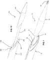
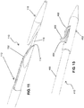
- a bi-polar tapered tip catheter embodiment 10 which comprises an elongate outer tube 12 having an outer diameter that can range from 3F - 12F. It may be manufactured from a variety of materials, either polymer or metallic. It comprises a central lumen 14, within which a tubular structure 16 for attaching a tip 18 may slide. There are separate lumina that run down the elongated core of the outer tube 12 for wiring to power electrodes or heating elements 20, 22 (proximal and distal, respectively), disposed on aligned tapered faces of the respective elongate outer tube 12 and distal tip 18, and to also measure the temperature during the coaptation and cutting processes.
- the catheter is powered using bipolar energy to the distal RF electrode 22 and the proximal RF electrode 20.
- the system can also be used in a monopolar configuration by grounding the patient and applying energy to one or both of the RF electrodes to increase the length of the coaptation.
- the RF electrodes cut at matching angles to increase the surface area of the coaptation and fistula size relative to the catheter diameter. These angles can be adjusted to achieve the desired fistula sizing.
- the RF electrodes are only electrically conductive on the front faces to maximize energy density.
- the electrodes are oval-shaped, and are adapted to cut an anastomosis which is larger than the diameter of the shaft 16.
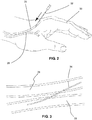
- the practitioner selects an appropriate procedural site having each of a first vessel 26 and a second vessel 28 in close proximity to one another.
- the first vessel 26 comprises a vein
- the second vessel 28 comprises an artery, but the invention is not necessarily limited to this arrangement.
- one presently preferred location is the hand 30 of a patient.
- the first vessel 26 is punctured by a needle 32, which is inserted therein, for the purpose of introducing an access sheath into the site.
- suitable techniques such as the technique described in Provisional U.S. Application Serial No. 61/354,903, filed on June 15, 2010 and herein expressly incorporated by reference, in its entirety, a guidewire 34 is inserted into the patient, from the first vessel 26 into the second vessel 28, as shown in Fig. 3 .
- the guidewire 34 creates an access path for the catheter 10.
- the catheter 10 is inserted into the patient by loading a proximal end of the guidewire 34 into the tip 18, which is fabricated to be flexible and tapered.
- the catheter 10 is advanced further into the patient, tracking over the guidewire 34, until the tapered dilating distal tip 18 comes into contact with the selected anastomosis site.
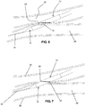
- the device 10 can be tracked over the guidewire with the distal tip extended (as shown in Fig. 5 ) or retracted (as shown in Fig. 4 ).
- the distal tip 18 is extended and further advanced into the second vessel 28 ( Fig.
- the distal tip 18 After the distal tip 18 is advanced into the second vessel 28, as illustrated in Fig. 6 , a slight tension is applied to the distal RF electrode 22 to seat it against the vessel wall.
- the blunt shape of the proximal end of the distal tip 18 prevents the distal tip from pulling back through the vessel wall.
- the proximal end of the device 10, namely the outer tube 12 is then advanced to close the spacing between the tube 12 and tip 18, until the walls of the first and second vessels 26, 28, respectively, are captured between the facing blunt surfaces of each of the outer tube 12 and distal tip 18.
- a controlled tension is maintained between the distal tip 18 and proximal outer tube 12, and at this juncture, with the vessel walls securely clamped, energy is applied to the RF electrodes 20, 22 ( Fig. 7 ).
- the RF electrodes 20, 22 As the electrodes weld and cut the vessels, the electrodes will move closer to one another. When fully retracted, the system 10 is designed so that the two electrodes 20, 22 cannot come into direct contact with one another, thus preventing the electrodes from shorting.
- a variety of RF energy profiles may be applied to achieve the desired coaptation and cutting. For example, during the coaptation phase, a tapered sine wave may be applied to maximize coagulation without cutting through the tissue. The energy may also be adjusted based upon the impedance of the tissue.
- the hot wire is an oval shape and cuts an anastomosis larger than the diameter of the shaft 16. Within the oval shape of the cutting elements, there is a cavity for capturing the tissue that has been cut.
- the outer sliding tube is usable to push the tissue off the heater in case there is a sticking problem due to the heat.
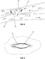
- the RF energy functions to burn and fuse or weld the vessels together, creating an elongate aperture 36 ( Fig. 8 ) through the opposing walls of each of the first and second vessels, as well as any intervening tissue.
- the elongate aperture 36 will typically resemble a slit.
- pressurized flow 38 begins to occur through the slit or aperture 36, which creates a communicating passage between the first vessel and the second vessel, the aperture widens responsive to the pressure, taking the shape of an ellipse as it opens to form the desired fistula. This effect is illustrated in Fig. 9 .
- the edges 40 of the aperture are cauterized and welded. Fig.
- the cut area corresponds to the shape of the heater wire. It can be of multiple shapes, such as round, oval, a slit, or a combination as shown.
- the area outside of the cut has been welded due to the flat face of the catheter in the vein (first vessel) being larger than the cutting wire.
- the heat from the wire is also preferably spread over this area by a conductive material that is below the heater, as will be described below. This creates a temperature gradient, which is a particularly advantageous feature of the present invention.
- Fig. 10 is a cross-sectional view of a handle portion 42 of the embodiment shown in Fig. 1 .
- This is one possible approach for actuating the extension and retraction of the distal tip 18 relative to the elongate outer tube 12, as discussed above, though many other suitable configurations may be used alternatively.
- a trigger 44 is slidably disposed on the handle 42, slidable distally through a slot 46 in the direction of arrow 48, and then retractable in the reverse direction.
- a spring 50 within the handle controls pressure, and a locking mechanism functions to lock the trigger 44 in the retracted state.
- FIG. 11 illustrates an alternative embodiment, wherein a catheter 110 comprises an elongate outer tube 112 having a central lumen 114, a tubular structure 116, and a flexible and tapered distal tip 118.
- a single resistive heating wire 152 is used to provide the tissue heating, cutting, and welding function described above.
- an RF configuration applying only monopolar energy, to either the venous or arterial sides, may be employed. A combination of RF energy and resistance heating may also be used.
- the tip 118 tracks over the guidewire and dilates the anastomosis site, as in the previous embodiment.
- the tapered faces of the members 112 and 118 align.
- the single hot wire 152 down the face cuts a slit in the vessel walls, and the faces are tapered to assist in removing the device.
- the catheter 210 comprises a resistive heating element 252, which is employed in a manner similar to that described above in connection with the Fig. 11 embodiment.
- a conductive material 254 is disposed beneath the heating element 252.
- this conductive material 254 comprises aluminum, though other conductive bio-compatible materials may also be used.
- this conductive material 254 functions to create a heat gradient from the heating element 252, for the purpose of improving the welding function, as described above.
- the tip 218 tracks over the guidewire and dilates the anastomosis site.
- the tapered faces of each of the members 212 and 218 align, for clamping the vessel walls.
- the hot wire 252 is an oval shape and has vertical strips 256 on both sides of the artery.
- the hot wire cuts an anastomosis larger than the diameter of the shaft 216.
- the heat conductive material 254 pulls heat away from the hot wire so that there is a temperature gradient across the face, with the temperature being hottest in the center and cooling as the distance outwardly from the center increases.
- the hot wire 252 (heater) is raised above the spreader 254 to increase pressure on the tissue, to thereby assist in the cutting process. Inside the hot wire, there is a cavity to capture the tissue that has been cut.
- the profile of the distal tip 218 aligns with the edge of the heater when retracted. It is a lower profile than the heat spreader, so that it can be retracted back through the fistula. This also increases the pressure directly on the heater surface to assist in cutting function.
- Figs. 13 and 14 illustrate still another embodiment 310, comprising a distal toggle member 358.
- the cutting elements in this embodiment are substantially identical to those shown and described in connection with Fig. 12 .
- the toggle 358 tracks over the guidewire into the artery. When retracted ( Fig. 15 ), the toggle captures the artery and pulls against the vein.
- the hot wire is an oval shape, has vertical strips 356 on both sides of the artery, and cuts an anastomosis larger than the diameter of the shaft 316. Under the hot wire 352, there is a heat conductive material 356 that pulls heat away from the hot wire so that there is a temperature gradient across the face.
- the hot wire is raised above the heat spreader to increase pressure on the tissue to help it cut through. Inside the hot wire there is a cavity to capture the tissue that has been cut.
- the profile of the toggle 358 aligns with the edge of the heater when retracted. It is of a lower profile than the heat spreader so that it can be retracted back through the fistula. This also increases the pressure directly on the heater surface and helps it cut. Heating elements may also be disposed on the toggle surface to work in conjunction with the heater 352 to cut and weld tissue.
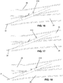
- the cutting device 410 comprises a shaft 460 having a distal portion 462.
- the distal portion comprises a side port 464, from which extends a heater wire 466 which is supported by a flexible clamp 468, preferably fabricated from nitinol or similar material.
- the heater wire may be resistive or utilize any other energy source as described above.
- Figs. 16-18 access to the anastomosis site is gained by methods as described above and the function of this device, once in place, is to manipulate the wire 466, using the flexible clamp 468 and suitable actuation mechanisms in order to create a fistula of a desired configuration.
- the tip 462 tracks over the guidewire 34 and dilates the anastomosis site, as in previously described approaches.
- the catheter 410 is advanced so that the clip 466 is all the way in the artery 28, and then puled back to capture the arterial wall under the clip, as illustrated in Fig. 17 .
- the wire is then activated to heat, and then drawn back, which cuts through the arterial and venous walls.
- the hot wire is then pulled back ( Fig. 18 ), and pulls down the clip portion through the vessel walls.
Landscapes
- Health & Medical Sciences (AREA)
- Surgery (AREA)
- Life Sciences & Earth Sciences (AREA)
- Engineering & Computer Science (AREA)
- Molecular Biology (AREA)
- Public Health (AREA)
- Heart & Thoracic Surgery (AREA)
- Medical Informatics (AREA)
- Nuclear Medicine, Radiotherapy & Molecular Imaging (AREA)
- Animal Behavior & Ethology (AREA)
- General Health & Medical Sciences (AREA)
- Biomedical Technology (AREA)
- Veterinary Medicine (AREA)
- Physics & Mathematics (AREA)
- Plasma & Fusion (AREA)
- Otolaryngology (AREA)
- Cardiology (AREA)
- Surgical Instruments (AREA)
Claims (11)
- Dispositif (10) destiné à la création d'une fistule artérioveineuse (AV), comprenant :un élément allongé (12) comprenantune face biseautée distale (12) ;un élément distal (18) raccordé à l'élément allongé et mobile par rapport à l'élément allongé etun axe (16) destiné au raccordement de l'extrémité distale de l'élément distal à l'élément allongé, l'axe étant extensible et rétractable pour étendre et rétracter ledit élément distal par rapport à l'élément allongé, dans lequel lorsque l'extrémité distale de l'élément distal est rétractée, par rapport à l'élément allongé, la face biseautée distale et la face biseautée proximale sont pratiquement en prise pour serrer le tissu entre elles ; et caractérisé en ce que l'élément distal est composé d'une face biseautée proximale qui est pratiquement alignée avec la face biseautée distale de l'élément allongé et le dispositif comprenant en outreun élément chauffant (20, 22) disposé sur au moins une parmi la face biseautée proximale de l'élément distal et ladite face biseautée distale de l'élément allongé ;dans lequel ledit élément chauffant est conçu pour couper à travers ledit tissu serré pour créer la fistule.
- Dispositif tel que décrit dans la revendication 1, dans lequel ledit élément allongé comprend un tube extérieur allongé.
- Dispositif tel que décrit dans la revendication 1, dans lequel ledit élément chauffant est disposé sur ladite face biseautée proximale.
- Dispositif tel que décrit dans la revendication 3 et comprenant en outre un second élément chauffant disposé sur ladite face biseautée distale.
- Dispositif tel que décrit dans la revendication 4, dans lequel au moins un parmi ledit élément chauffant et ledit second élément chauffant comprend un appareil de chauffage sous tension et un diffuseur de chaleur disposés sous l'appareil de chauffage sous tension pour diffuser la chaleur à l'opposé de l'appareil de chauffage et créer un gradient de température.
- Dispositif tel que décrit dans la revendication 5, dans lequel ledit élément chauffant comprend un matériau conducteur de chaleur et est disposé sous la face biseautée de l'élément chauffant.
- Dispositif tel que décrit dans la revendication 1, dans lequel ledit élément distal est conique et souple.
- Dispositif tel que décrit dans la revendication 1, dans lequel ledit élément chauffant est disposé sur ladite face biseautée distale dudit élément allongé.
- Dispositif tel que décrit dans la revendication 8 et comprenant en outre une cavité recevant le tissu associé audit élément chauffant.
- Dispositif tel que décrit dans la revendication 8, dans lequel ledit élément chauffant comprend un appareil de chauffage sous tension et un diffuseur de chaleur disposés sous l'élément chauffant sous tension pour diffuser la chaleur à l'opposé de l'appareil de chauffage et créer un gradient de température.
- Dispositif tel que décrit dans la revendication 10, dans lequel ledit diffuseur de chaleur comprend un matériau conducteur de la chaleur.
Applications Claiming Priority (3)
| Application Number | Priority Date | Filing Date | Title |
|---|---|---|---|
| US35490310P | 2010-06-15 | 2010-06-15 | |
| US201161480818P | 2011-04-29 | 2011-04-29 | |
| PCT/US2011/040567 WO2011159825A1 (fr) | 2010-06-15 | 2011-06-15 | Anastomose intravasculaire d'une artère à une veine, et cathéter pour soudage de tissu |
Publications (3)
| Publication Number | Publication Date |
|---|---|
| EP2582314A1 EP2582314A1 (fr) | 2013-04-24 |
| EP2582314A4 EP2582314A4 (fr) | 2017-08-02 |
| EP2582314B1 true EP2582314B1 (fr) | 2019-12-18 |
Family
ID=45096810
Family Applications (1)
| Application Number | Title | Priority Date | Filing Date |
|---|---|---|---|
| EP11796389.2A Active EP2582314B1 (fr) | 2010-06-15 | 2011-06-15 | Anastomose intravasculaire d'une artère à une veine, et cathéter pour soudage de tissu |
Country Status (7)
| Country | Link |
|---|---|
| US (4) | US9452015B2 (fr) |
| EP (1) | EP2582314B1 (fr) |
| JP (1) | JP5916237B2 (fr) |
| AU (1) | AU2011268346B2 (fr) |
| CA (1) | CA2804525C (fr) |
| DK (1) | DK2582314T3 (fr) |
| WO (1) | WO2011159825A1 (fr) |
Cited By (2)
| Publication number | Priority date | Publication date | Assignee | Title |
|---|---|---|---|---|
| CN108366822A (zh) * | 2015-08-21 | 2018-08-03 | 艾凡诺医疗公司 | 经皮动静脉造瘘的系统与方法 |
| WO2024030119A1 (fr) * | 2022-08-02 | 2024-02-08 | Tva Medical, Inc. | Cathéters et procédés de traitement endovasculaire avec des électrodes |
Families Citing this family (37)
| Publication number | Priority date | Publication date | Assignee | Title |
|---|---|---|---|---|
| GB0419954D0 (en) | 2004-09-08 | 2004-10-13 | Advotek Medical Devices Ltd | System for directing therapy |
| US20130190676A1 (en) | 2006-04-20 | 2013-07-25 | Limflow Gmbh | Devices and methods for fluid flow through body passages |
| EP2582314B1 (fr) | 2010-06-15 | 2019-12-18 | Avenu Medical, Inc. | Anastomose intravasculaire d'une artère à une veine, et cathéter pour soudage de tissu |
| ES2910440T3 (es) | 2010-11-16 | 2022-05-12 | Tva Medical Inc | Dispositivos para formar una fístula |
| US9474562B2 (en) | 2012-02-08 | 2016-10-25 | Avenu Medical, Inc. | Intravascular arterial to venous anastomosis and tissue welding catheter |
| US20140039478A1 (en) * | 2012-08-01 | 2014-02-06 | Caymus Medical, Inc. | Systems and methods for percutaneous intravascular access for arteriovenous fistula |
| CA2887557C (fr) | 2012-10-11 | 2022-05-17 | Tva Medical, Inc. | Dispositifs et procedes pour la formation de fistules |
| WO2014078601A1 (fr) * | 2012-11-14 | 2014-05-22 | Caymus Medical, Inc. | Anastomose artério-veineuse intravasculaire et cathéter de soudage de tissu |
| CA3191733A1 (fr) | 2013-03-08 | 2014-09-12 | Limflow Gmbh | Procedes et systemes pour etablir ou maintenir un ecoulement de fluide a travers des passages de corps |
| JP6527134B2 (ja) | 2013-03-14 | 2019-06-05 | ティーブイエー メディカル, インコーポレイテッド | 瘻孔作成装置およびそのための方法 |
| US10070866B1 (en) | 2013-08-01 | 2018-09-11 | Avenu Medical, Inc. | Percutaneous arterial to venous anastomosis clip application catheter system and methods |
| US10292708B1 (en) | 2014-02-13 | 2019-05-21 | Avenu Medical, Inc. | Externally supported anastomosis |
| US10772672B2 (en) * | 2014-03-06 | 2020-09-15 | Avenu Medical, Inc. | Systems and methods for percutaneous access and formation of arteriovenous fistulas |
| WO2015138998A1 (fr) | 2014-03-14 | 2015-09-17 | Tva Medical, Inc. | Dispositif de formation de fistule, et méthodes associées |
| US10646666B2 (en) | 2014-08-27 | 2020-05-12 | Tva Medical, Inc. | Cryolipolysis devices and methods therefor |
| US10603040B1 (en) | 2015-02-09 | 2020-03-31 | Tva Medical, Inc. | Methods for treating hypertension and reducing blood pressure with formation of fistula |
| WO2017124059A1 (fr) | 2016-01-15 | 2017-07-20 | Tva Medical, Inc. | Dispositifs et procédés pour faire avancer un fil |
| US10874422B2 (en) | 2016-01-15 | 2020-12-29 | Tva Medical, Inc. | Systems and methods for increasing blood flow |
| WO2017124060A1 (fr) * | 2016-01-15 | 2017-07-20 | Tva Medical, Inc. | Systèmes et procédés pour faire adhérer des vaisseaux |
| BR112018014112A8 (pt) | 2016-01-15 | 2023-02-23 | Tva Medical Inc | Dispositivos e métodos para formação de uma fístula |
| US11285028B2 (en) | 2016-09-25 | 2022-03-29 | Tva Medical, Inc. | Vascular stent devices and methods |
| WO2018089689A1 (fr) | 2016-11-11 | 2018-05-17 | Avenu Medical, Inc. | Systèmes et procédés servant à un accès intravasculaire percutané et le placement d'un fil-guide |
| WO2018189593A2 (fr) | 2017-04-10 | 2018-10-18 | Limflow Gmbh | Dispositifs et méthodes de traitement du système vasculaire des extrémités inférieures |
| US11937821B1 (en) | 2017-05-17 | 2024-03-26 | Avenu Medical, Inc. | Systems and methods for catheter feedback and control for AV fistula creation |
| WO2018213626A1 (fr) | 2017-05-17 | 2018-11-22 | Avenu Medical, Inc. | Système de découpe de tissu par électrode de cathéter unique destiné à créer des anastomoses |
| US11564728B1 (en) * | 2017-12-14 | 2023-01-31 | Avenu Medical, Inc. | Systems and methods for percutaneous access, formation, and maintenance of arteriovenous fistulas |
| JP6982188B2 (ja) * | 2017-12-19 | 2021-12-17 | インテュイティブ サージカル オペレーションズ, インコーポレイテッド | 同時の電気手術シーリング及び切断 |
| US11564690B1 (en) | 2018-02-22 | 2023-01-31 | Avenu Medical, Inc | Vascular flow control devices and methods |
| EP3829457A4 (fr) * | 2018-08-03 | 2022-04-20 | Avenu Medical, Inc. | Fixation de vaisseaux pour la création d'une fistule percutanée |
| WO2020076833A1 (fr) | 2018-10-09 | 2020-04-16 | Limflow Gmbh | Dispositifs et procédés d'alignement de cathéter |
| US20210077186A1 (en) * | 2019-09-13 | 2021-03-18 | Alleviant Medical, Inc. | Systems, devices, and methods for forming an anastomosis |
| US11793623B1 (en) | 2019-10-14 | 2023-10-24 | Avenu Medical, Inc | Systems and methods for percutaneously placing biologic grafts at a procedural site |
| JP2023500067A (ja) | 2019-11-01 | 2023-01-04 | リムフロウ・ゲゼルシャフト・ミット・ベシュレンクテル・ハフツング | 肢遠位部への血液灌流を増加させるための装置及び方法 |
| US20210177508A1 (en) * | 2019-12-12 | 2021-06-17 | Avenu Medical, Inc. | Devices and methods for the creation of an inter-atrial shunt for the treatment of congestive heart failure |
| CA3201019A1 (fr) * | 2020-11-09 | 2022-05-12 | Venova Medical, Inc. | Implants endovasculaires ainsi que dispositifs et procedes de placement precis |
| EP4074352A1 (fr) | 2021-04-12 | 2022-10-19 | Mallios Consulting | Dispositifs de formation d'anastomose vasculaire percutanée, en particulier de fistule artério-veineuse percutanée pour l'hémodialyse |
| WO2024132104A1 (fr) * | 2022-12-20 | 2024-06-27 | Clearstream Technologies Limited | Dispositif médical pour former une fistule |
Family Cites Families (82)
| Publication number | Priority date | Publication date | Assignee | Title |
|---|---|---|---|---|
| US4772283A (en) | 1986-05-16 | 1988-09-20 | White Thomas C | Corneal implant |
| US5409453A (en) * | 1992-08-12 | 1995-04-25 | Vidamed, Inc. | Steerable medical probe with stylets |
| DE69230494T2 (de) | 1991-04-05 | 2000-06-08 | Metcal Inc., Menlo Park | Instrument zum schneiden, koagulieren und abtragen von gewebe |
| NL9200828A (nl) | 1992-05-08 | 1993-12-01 | M A Rademaker B V Maschf | Werkwijze voor het positioneren van deegstukken en inrichtingen voor de uitvoering ervan. |
| US5290278A (en) | 1992-10-20 | 1994-03-01 | Proclosure Inc. | Method and apparatus for applying thermal energy to luminal tissue |
| US6749604B1 (en) | 1993-05-10 | 2004-06-15 | Arthrocare Corporation | Electrosurgical instrument with axially-spaced electrodes |
| US5544230A (en) | 1993-08-05 | 1996-08-06 | Megyesi; Timothy J. | Method and apparatus for recording and playing back a telemarketing sales presentation |
| US6056744A (en) | 1994-06-24 | 2000-05-02 | Conway Stuart Medical, Inc. | Sphincter treatment apparatus |
| US5578030A (en) * | 1994-11-04 | 1996-11-26 | Levin; John M. | Biopsy needle with cauterization feature |
| US6068637A (en) | 1995-10-03 | 2000-05-30 | Cedar Sinai Medical Center | Method and devices for performing vascular anastomosis |
| US6283983B1 (en) | 1995-10-13 | 2001-09-04 | Transvascular, Inc. | Percutaneous in-situ coronary bypass method and apparatus |
| US6302875B1 (en) | 1996-10-11 | 2001-10-16 | Transvascular, Inc. | Catheters and related devices for forming passageways between blood vessels or other anatomical structures |
| US6375615B1 (en) | 1995-10-13 | 2002-04-23 | Transvascular, Inc. | Tissue penetrating catheters having integral imaging transducers and their methods of use |
| US6726677B1 (en) | 1995-10-13 | 2004-04-27 | Transvascular, Inc. | Stabilized tissue penetrating catheters |
| US6190353B1 (en) | 1995-10-13 | 2001-02-20 | Transvascular, Inc. | Methods and apparatus for bypassing arterial obstructions and/or performing other transvascular procedures |
| CA2234389A1 (fr) | 1995-10-13 | 1997-04-17 | Transvascular, Inc. | Dispositif, systeme et procede permettant une intervention interstitielle transvasculaire |
| US5769086A (en) * | 1995-12-06 | 1998-06-23 | Biopsys Medical, Inc. | Control system and method for automated biopsy device |
| US6709444B1 (en) | 1996-02-02 | 2004-03-23 | Transvascular, Inc. | Methods for bypassing total or near-total obstructions in arteries or other anatomical conduits |
| ATE247429T1 (de) | 1996-02-02 | 2003-09-15 | Transvascular Inc | System für interstitielle transvaskuläre chirurgische eingriffe |
| EP0932426A4 (fr) | 1996-02-02 | 2003-07-30 | Transvascular Inc | Methodes et dispositifs permettant de relier des ouvertures menagees dans des vaisseaux sanguins contigus ou d'autres structures anatomiques |
| US5830224A (en) | 1996-03-15 | 1998-11-03 | Beth Israel Deaconess Medical Center | Catheter apparatus and methodology for generating a fistula on-demand between closely associated blood vessels at a pre-chosen anatomic site in-vivo |
| US5957920A (en) * | 1997-08-28 | 1999-09-28 | Isothermix, Inc. | Medical instruments and techniques for treatment of urinary incontinence |
| US6352535B1 (en) * | 1997-09-25 | 2002-03-05 | Nanoptics, Inc. | Method and a device for electro microsurgery in a physiological liquid environment |
| US6379319B1 (en) | 1996-10-11 | 2002-04-30 | Transvascular, Inc. | Systems and methods for directing and snaring guidewires |
| US6541028B1 (en) | 1997-01-17 | 2003-04-01 | Celadon Science, Llc | Methods for promoting healing of corneal resurfacing wounds |
| US5893369A (en) * | 1997-02-24 | 1999-04-13 | Lemole; Gerald M. | Procedure for bypassing an occlusion in a blood vessel |
| US6626901B1 (en) | 1997-03-05 | 2003-09-30 | The Trustees Of Columbia University In The City Of New York | Electrothermal instrument for sealing and joining or cutting tissue |
| US7083613B2 (en) | 1997-03-05 | 2006-08-01 | The Trustees Of Columbia University In The City Of New York | Ringed forceps |
| IL132195A0 (en) | 1997-04-11 | 2001-03-19 | Transvascular Inc | Method and apparatus for transmyocardial direct coronary revascularization |
| US6071292A (en) | 1997-06-28 | 2000-06-06 | Transvascular, Inc. | Transluminal methods and devices for closing, forming attachments to, and/or forming anastomotic junctions in, luminal anatomical structures |
| US6083223A (en) | 1997-08-28 | 2000-07-04 | Baker; James A. | Methods and apparatus for welding blood vessels |
| DE19739699A1 (de) * | 1997-09-04 | 1999-03-11 | Laser & Med Tech Gmbh | Elektrodenanordnung zur elektro-thermischen Behandlung des menschlichen oder tierischen Körpers |
| US6024739A (en) | 1997-09-05 | 2000-02-15 | Cordis Webster, Inc. | Method for detecting and revascularizing ischemic myocardial tissue |
| US6267761B1 (en) | 1997-09-09 | 2001-07-31 | Sherwood Services Ag | Apparatus and method for sealing and cutting tissue |
| US6330884B1 (en) | 1997-11-14 | 2001-12-18 | Transvascular, Inc. | Deformable scaffolding multicellular stent |
| US20070276363A1 (en) | 1998-02-12 | 2007-11-29 | Boris E. Paton | Instrument and method for the end-to-end reconnection of intestinal tissues |
| US6077260A (en) | 1998-02-19 | 2000-06-20 | Target Therapeutics, Inc. | Assembly containing an electrolytically severable joint for endovascular embolic devices |
| IL138666A0 (en) | 1998-03-31 | 2001-10-31 | Transvascular Inc | Catheters, systems and methods for percutaneous in situ arterio-venous bypass |
| US6561998B1 (en) | 1998-04-07 | 2003-05-13 | Transvascular, Inc. | Transluminal devices, systems and methods for enlarging interstitial penetration tracts |
| US6235027B1 (en) | 1999-01-21 | 2001-05-22 | Garrett D. Herzon | Thermal cautery surgical forceps |
| US6391038B2 (en) | 1999-07-28 | 2002-05-21 | Cardica, Inc. | Anastomosis system and method for controlling a tissue site |
| US6464665B1 (en) | 2000-07-05 | 2002-10-15 | Richard R. Heuser | Catheter apparatus and method for arterializing a vein |
| US6699245B2 (en) | 2001-02-05 | 2004-03-02 | A-Med Systems, Inc. | Anastomosis system and related methods |
| US7083618B2 (en) | 2001-04-06 | 2006-08-01 | Sherwood Services Ag | Vessel sealer and divider |
| US20030229344A1 (en) | 2002-01-22 | 2003-12-11 | Dycus Sean T. | Vessel sealer and divider and method of manufacturing same |
| EP1399071B1 (fr) | 2001-06-26 | 2010-06-16 | Tyco Healthcare Group Lp | Instrument de prelevement de vaisseaux sanguins |
| US6632227B2 (en) | 2001-08-24 | 2003-10-14 | Scimed Life Systems, Inc. | Endoscopic resection devices |
| US7029482B1 (en) | 2002-01-22 | 2006-04-18 | Cardica, Inc. | Integrated anastomosis system |
| US7223274B2 (en) | 2002-01-23 | 2007-05-29 | Cardica, Inc. | Method of performing anastomosis |
| AU2003219975A1 (en) | 2002-03-04 | 2003-09-22 | The Cleveland Clinic Foundation | Method and apparatus for controlling ablation in refractive surgery |
| US7074220B2 (en) | 2002-04-03 | 2006-07-11 | Thomas J. Fogarty | Methods and systems for vein harvesting and fistula creation |
| EP1496956B1 (fr) | 2002-04-11 | 2011-04-06 | Medtronic Vascular, Inc. | Dispositifs de placement d'éléctrode transluminale ou interstitielle transthoracique |
| US7351247B2 (en) | 2002-09-04 | 2008-04-01 | Bioconnect Systems, Inc. | Devices and methods for interconnecting body conduits |
| US6960209B2 (en) * | 2002-10-23 | 2005-11-01 | Medtronic, Inc. | Electrosurgical methods and apparatus for making precise incisions in body vessels |
| CA2523675C (fr) | 2003-05-01 | 2016-04-26 | Sherwood Services Ag | Instrument electrochirurgical reduisant les dommages thermiques causes aux tissus adjacents |
| US7628810B2 (en) | 2003-05-28 | 2009-12-08 | Acufocus, Inc. | Mask configured to maintain nutrient transport without producing visible diffraction patterns |
| US7988690B2 (en) | 2004-01-30 | 2011-08-02 | W.L. Gore & Associates, Inc. | Welding systems useful for closure of cardiac openings |
| US7255675B2 (en) | 2004-03-23 | 2007-08-14 | Michael Gertner | Devices and methods to treat a patient |
| US20050251167A1 (en) | 2004-05-07 | 2005-11-10 | Ethicon Endo-Surgery, Inc. | Instrument for effecting anastomosis of respective tissues defining two body lumens |
| EP1750607A2 (fr) * | 2004-06-02 | 2007-02-14 | Medtronic, Inc. | Appareil et methode d'ablation a boucle |
| US20100145331A1 (en) * | 2004-06-02 | 2010-06-10 | Chrisitian Steven C | Loop Ablation Apparatus and Method |
| WO2005122919A2 (fr) | 2004-06-14 | 2005-12-29 | Rox Medical, Inc. | Procedes, dispositifs et systemes destines a la creation d'une fistule arterielle et veineuse |
| US7824408B2 (en) | 2004-08-05 | 2010-11-02 | Tyco Healthcare Group, Lp | Methods and apparatus for coagulating and/or constricting hollow anatomical structures |
| US20060111704A1 (en) * | 2004-11-22 | 2006-05-25 | Rox Medical, Inc. | Devices, systems, and methods for energy assisted arterio-venous fistula creation |
| US8328797B2 (en) | 2004-12-23 | 2012-12-11 | C. R. Bard, Inc. | Blood vessel transecting and anastomosis |
| US7625372B2 (en) | 2005-02-23 | 2009-12-01 | Vnus Medical Technologies, Inc. | Methods and apparatus for coagulating and/or constricting hollow anatomical structures |
| US8197472B2 (en) * | 2005-03-25 | 2012-06-12 | Maquet Cardiovascular, Llc | Tissue welding and cutting apparatus and method |
| US7918848B2 (en) | 2005-03-25 | 2011-04-05 | Maquet Cardiovascular, Llc | Tissue welding and cutting apparatus and method |
| US7422138B2 (en) | 2006-02-01 | 2008-09-09 | Ethicon Endo-Surgery, Inc. | Elliptical intraluminal surgical stapler for anastomosis |
| EP2035062A4 (fr) * | 2006-07-05 | 2013-01-16 | Jms North America Corp | Gaine de protection d'aiguille avec pointe de préparation de site |
| US9492220B2 (en) | 2007-02-01 | 2016-11-15 | Conmed Corporation | Apparatus and method for rapid reliable electrothermal tissue fusion |
| US20080312651A1 (en) | 2007-06-15 | 2008-12-18 | Karl Pope | Apparatus and methods for selective heating of tissue |
| US20090048589A1 (en) | 2007-08-14 | 2009-02-19 | Tomoyuki Takashino | Treatment device and treatment method for living tissue |
| KR101565441B1 (ko) | 2008-04-30 | 2015-11-03 | 각코우호우진 지치 이카다이가쿠 | 무흉터 수술(notes)용 외과 수술 시스템 |
| US9968396B2 (en) | 2008-05-27 | 2018-05-15 | Maquet Cardiovascular Llc | Surgical instrument and method |
| US8267951B2 (en) | 2008-06-12 | 2012-09-18 | Ncontact Surgical, Inc. | Dissecting cannula and methods of use thereof |
| US9820746B2 (en) * | 2008-07-28 | 2017-11-21 | Incube Laboratories LLC | System and method for scaffolding anastomoses |
| US20110011916A1 (en) | 2009-07-16 | 2011-01-20 | New York University | Anastomosis device |
| US8623044B2 (en) | 2010-04-12 | 2014-01-07 | Ethicon Endo-Surgery, Inc. | Cable actuated end-effector for a surgical instrument |
| US8709035B2 (en) | 2010-04-12 | 2014-04-29 | Ethicon Endo-Surgery, Inc. | Electrosurgical cutting and sealing instruments with jaws having a parallel closure motion |
| EP2582314B1 (fr) | 2010-06-15 | 2019-12-18 | Avenu Medical, Inc. | Anastomose intravasculaire d'une artère à une veine, et cathéter pour soudage de tissu |
| ES2910440T3 (es) | 2010-11-16 | 2022-05-12 | Tva Medical Inc | Dispositivos para formar una fístula |
-
2011
- 2011-06-15 EP EP11796389.2A patent/EP2582314B1/fr active Active
- 2011-06-15 WO PCT/US2011/040567 patent/WO2011159825A1/fr active Application Filing
- 2011-06-15 US US13/161,356 patent/US9452015B2/en active Active
- 2011-06-15 AU AU2011268346A patent/AU2011268346B2/en active Active
- 2011-06-15 CA CA2804525A patent/CA2804525C/fr active Active
- 2011-06-15 JP JP2013515487A patent/JP5916237B2/ja active Active
- 2011-06-15 DK DK11796389.2T patent/DK2582314T3/da active
-
2016
- 2016-04-22 US US15/136,794 patent/US9931164B2/en active Active
-
2018
- 2018-03-29 US US15/940,667 patent/US11083518B2/en active Active
-
2021
- 2021-07-17 US US17/378,684 patent/US20210338324A1/en active Pending
Non-Patent Citations (1)
| Title |
|---|
| None * |
Cited By (3)
| Publication number | Priority date | Publication date | Assignee | Title |
|---|---|---|---|---|
| CN108366822A (zh) * | 2015-08-21 | 2018-08-03 | 艾凡诺医疗公司 | 经皮动静脉造瘘的系统与方法 |
| CN108366822B (zh) * | 2015-08-21 | 2021-02-19 | 艾凡诺医疗公司 | 经皮动静脉造瘘的系统与方法 |
| WO2024030119A1 (fr) * | 2022-08-02 | 2024-02-08 | Tva Medical, Inc. | Cathéters et procédés de traitement endovasculaire avec des électrodes |
Also Published As
| Publication number | Publication date |
|---|---|
| JP5916237B2 (ja) | 2016-05-11 |
| CA2804525A1 (fr) | 2011-12-22 |
| DK2582314T3 (da) | 2020-03-02 |
| US20210338324A1 (en) | 2021-11-04 |
| AU2011268346B2 (en) | 2014-07-17 |
| US9452015B2 (en) | 2016-09-27 |
| US20110306959A1 (en) | 2011-12-15 |
| EP2582314A1 (fr) | 2013-04-24 |
| US9931164B2 (en) | 2018-04-03 |
| WO2011159825A1 (fr) | 2011-12-22 |
| US11083518B2 (en) | 2021-08-10 |
| US20180310990A1 (en) | 2018-11-01 |
| CA2804525C (fr) | 2018-09-04 |
| AU2011268346A1 (en) | 2013-01-24 |
| US20160235410A1 (en) | 2016-08-18 |
| EP2582314A4 (fr) | 2017-08-02 |
| JP2013545494A (ja) | 2013-12-26 |
Similar Documents
| Publication | Publication Date | Title |
|---|---|---|
| US20210338324A1 (en) | Intravascular arterial to venous anastomosis and tissue welding catheter | |
| US11950828B2 (en) | Intravascular arterial to venous anastomosis and tissue welding catheter | |
| US11690944B2 (en) | Systems and methods for creating arteriovenous (AV) fistulas | |
| US11457970B2 (en) | Intravascular arterial to venous anastomosis and tissue welding catheter | |
| US9955972B1 (en) | Systems and methods for creating arteriovenous (AV) fistulas |
Legal Events
| Date | Code | Title | Description |
|---|---|---|---|
| PUAI | Public reference made under article 153(3) epc to a published international application that has entered the european phase |
Free format text: ORIGINAL CODE: 0009012 |
|
| 17P | Request for examination filed |
Effective date: 20130110 |
|
| AK | Designated contracting states |
Kind code of ref document: A1 Designated state(s): AL AT BE BG CH CY CZ DE DK EE ES FI FR GB GR HR HU IE IS IT LI LT LU LV MC MK MT NL NO PL PT RO RS SE SI SK SM TR |
|
| RAP1 | Party data changed (applicant data changed or rights of an application transferred) |
Owner name: BAJA RESEARCH, LLC Owner name: AVENU MEDICAL, INC. |
|
| RA4 | Supplementary search report drawn up and despatched (corrected) |
Effective date: 20170703 |
|
| RIC1 | Information provided on ipc code assigned before grant |
Ipc: A61B 17/11 20060101ALI20170627BHEP Ipc: A61B 18/00 20060101ALI20170627BHEP Ipc: A61B 18/14 20060101ALI20170627BHEP Ipc: A61B 17/08 20060101AFI20170627BHEP |
|
| REG | Reference to a national code |
Ref country code: DE Ref legal event code: R079 Ref document number: 602011064113 Country of ref document: DE Free format text: PREVIOUS MAIN CLASS: A61B0018080000 Ipc: A61B0017080000 |
|
| GRAP | Despatch of communication of intention to grant a patent |
Free format text: ORIGINAL CODE: EPIDOSNIGR1 |
|
| STAA | Information on the status of an ep patent application or granted ep patent |
Free format text: STATUS: GRANT OF PATENT IS INTENDED |
|
| RIC1 | Information provided on ipc code assigned before grant |
Ipc: A61B 17/11 20060101ALI20190528BHEP Ipc: A61B 18/14 20060101ALI20190528BHEP Ipc: A61B 18/00 20060101ALI20190528BHEP Ipc: A61B 17/08 20060101AFI20190528BHEP |
|
| INTG | Intention to grant announced |
Effective date: 20190703 |
|
| GRAS | Grant fee paid |
Free format text: ORIGINAL CODE: EPIDOSNIGR3 |
|
| RAP1 | Party data changed (applicant data changed or rights of an application transferred) |
Owner name: BAJA RESEARCH, LLC Owner name: AVENU MEDICAL, INC. |
|
| RIN1 | Information on inventor provided before grant (corrected) |
Inventor name: RITCHART, MARK, A. Inventor name: WROLSTAD, DAVID, K. Inventor name: HULL, JEFFREY, E. Inventor name: ALDRIDGE, DAVID, TROTTINGWOLF Inventor name: KELLERMAN, BRAD, M. |
|
| GRAA | (expected) grant |
Free format text: ORIGINAL CODE: 0009210 |
|
| STAA | Information on the status of an ep patent application or granted ep patent |
Free format text: STATUS: THE PATENT HAS BEEN GRANTED |
|
| AK | Designated contracting states |
Kind code of ref document: B1 Designated state(s): AL AT BE BG CH CY CZ DE DK EE ES FI FR GB GR HR HU IE IS IT LI LT LU LV MC MK MT NL NO PL PT RO RS SE SI SK SM TR |
|
| REG | Reference to a national code |
Ref country code: GB Ref legal event code: FG4D |
|
| REG | Reference to a national code |
Ref country code: CH Ref legal event code: EP |
|
| REG | Reference to a national code |
Ref country code: IE Ref legal event code: FG4D |
|
| REG | Reference to a national code |
Ref country code: DE Ref legal event code: R096 Ref document number: 602011064113 Country of ref document: DE |
|
| REG | Reference to a national code |
Ref country code: AT Ref legal event code: REF Ref document number: 1213700 Country of ref document: AT Kind code of ref document: T Effective date: 20200115 |
|
| REG | Reference to a national code |
Ref country code: DK Ref legal event code: T3 Effective date: 20200227 |
|
| REG | Reference to a national code |
Ref country code: SE Ref legal event code: TRGR |
|
| REG | Reference to a national code |
Ref country code: NL Ref legal event code: FP |
|
| REG | Reference to a national code |
Ref country code: NO Ref legal event code: T2 Effective date: 20191218 |
|
| PG25 | Lapsed in a contracting state [announced via postgrant information from national office to epo] |
Ref country code: FI Free format text: LAPSE BECAUSE OF FAILURE TO SUBMIT A TRANSLATION OF THE DESCRIPTION OR TO PAY THE FEE WITHIN THE PRESCRIBED TIME-LIMIT Effective date: 20191218 Ref country code: LT Free format text: LAPSE BECAUSE OF FAILURE TO SUBMIT A TRANSLATION OF THE DESCRIPTION OR TO PAY THE FEE WITHIN THE PRESCRIBED TIME-LIMIT Effective date: 20191218 Ref country code: BG Free format text: LAPSE BECAUSE OF FAILURE TO SUBMIT A TRANSLATION OF THE DESCRIPTION OR TO PAY THE FEE WITHIN THE PRESCRIBED TIME-LIMIT Effective date: 20200318 Ref country code: LV Free format text: LAPSE BECAUSE OF FAILURE TO SUBMIT A TRANSLATION OF THE DESCRIPTION OR TO PAY THE FEE WITHIN THE PRESCRIBED TIME-LIMIT Effective date: 20191218 |
|
| REG | Reference to a national code |
Ref country code: LT Ref legal event code: MG4D |
|
| REG | Reference to a national code |
Ref country code: GR Ref legal event code: EP Ref document number: 20200400699 Country of ref document: GR Effective date: 20200518 |
|
| PG25 | Lapsed in a contracting state [announced via postgrant information from national office to epo] |
Ref country code: RS Free format text: LAPSE BECAUSE OF FAILURE TO SUBMIT A TRANSLATION OF THE DESCRIPTION OR TO PAY THE FEE WITHIN THE PRESCRIBED TIME-LIMIT Effective date: 20191218 Ref country code: HR Free format text: LAPSE BECAUSE OF FAILURE TO SUBMIT A TRANSLATION OF THE DESCRIPTION OR TO PAY THE FEE WITHIN THE PRESCRIBED TIME-LIMIT Effective date: 20191218 |
|
| PG25 | Lapsed in a contracting state [announced via postgrant information from national office to epo] |
Ref country code: AL Free format text: LAPSE BECAUSE OF FAILURE TO SUBMIT A TRANSLATION OF THE DESCRIPTION OR TO PAY THE FEE WITHIN THE PRESCRIBED TIME-LIMIT Effective date: 20191218 |
|
| PG25 | Lapsed in a contracting state [announced via postgrant information from national office to epo] |
Ref country code: RO Free format text: LAPSE BECAUSE OF FAILURE TO SUBMIT A TRANSLATION OF THE DESCRIPTION OR TO PAY THE FEE WITHIN THE PRESCRIBED TIME-LIMIT Effective date: 20191218 Ref country code: CZ Free format text: LAPSE BECAUSE OF FAILURE TO SUBMIT A TRANSLATION OF THE DESCRIPTION OR TO PAY THE FEE WITHIN THE PRESCRIBED TIME-LIMIT Effective date: 20191218 Ref country code: PT Free format text: LAPSE BECAUSE OF FAILURE TO SUBMIT A TRANSLATION OF THE DESCRIPTION OR TO PAY THE FEE WITHIN THE PRESCRIBED TIME-LIMIT Effective date: 20200513 Ref country code: EE Free format text: LAPSE BECAUSE OF FAILURE TO SUBMIT A TRANSLATION OF THE DESCRIPTION OR TO PAY THE FEE WITHIN THE PRESCRIBED TIME-LIMIT Effective date: 20191218 |
|
| PG25 | Lapsed in a contracting state [announced via postgrant information from national office to epo] |
Ref country code: SM Free format text: LAPSE BECAUSE OF FAILURE TO SUBMIT A TRANSLATION OF THE DESCRIPTION OR TO PAY THE FEE WITHIN THE PRESCRIBED TIME-LIMIT Effective date: 20191218 Ref country code: IS Free format text: LAPSE BECAUSE OF FAILURE TO SUBMIT A TRANSLATION OF THE DESCRIPTION OR TO PAY THE FEE WITHIN THE PRESCRIBED TIME-LIMIT Effective date: 20200418 Ref country code: SK Free format text: LAPSE BECAUSE OF FAILURE TO SUBMIT A TRANSLATION OF THE DESCRIPTION OR TO PAY THE FEE WITHIN THE PRESCRIBED TIME-LIMIT Effective date: 20191218 |
|
| REG | Reference to a national code |
Ref country code: DE Ref legal event code: R097 Ref document number: 602011064113 Country of ref document: DE |
|
| REG | Reference to a national code |
Ref country code: AT Ref legal event code: MK05 Ref document number: 1213700 Country of ref document: AT Kind code of ref document: T Effective date: 20191218 |
|
| PLBE | No opposition filed within time limit |
Free format text: ORIGINAL CODE: 0009261 |
|
| STAA | Information on the status of an ep patent application or granted ep patent |
Free format text: STATUS: NO OPPOSITION FILED WITHIN TIME LIMIT |
|
| PG25 | Lapsed in a contracting state [announced via postgrant information from national office to epo] |
Ref country code: ES Free format text: LAPSE BECAUSE OF FAILURE TO SUBMIT A TRANSLATION OF THE DESCRIPTION OR TO PAY THE FEE WITHIN THE PRESCRIBED TIME-LIMIT Effective date: 20191218 |
|
| 26N | No opposition filed |
Effective date: 20200921 |
|
| PG25 | Lapsed in a contracting state [announced via postgrant information from national office to epo] |
Ref country code: SI Free format text: LAPSE BECAUSE OF FAILURE TO SUBMIT A TRANSLATION OF THE DESCRIPTION OR TO PAY THE FEE WITHIN THE PRESCRIBED TIME-LIMIT Effective date: 20191218 Ref country code: AT Free format text: LAPSE BECAUSE OF FAILURE TO SUBMIT A TRANSLATION OF THE DESCRIPTION OR TO PAY THE FEE WITHIN THE PRESCRIBED TIME-LIMIT Effective date: 20191218 |
|
| PG25 | Lapsed in a contracting state [announced via postgrant information from national office to epo] |
Ref country code: MC Free format text: LAPSE BECAUSE OF FAILURE TO SUBMIT A TRANSLATION OF THE DESCRIPTION OR TO PAY THE FEE WITHIN THE PRESCRIBED TIME-LIMIT Effective date: 20191218 |
|
| REG | Reference to a national code |
Ref country code: CH Ref legal event code: PL |
|
| PG25 | Lapsed in a contracting state [announced via postgrant information from national office to epo] |
Ref country code: PL Free format text: LAPSE BECAUSE OF FAILURE TO SUBMIT A TRANSLATION OF THE DESCRIPTION OR TO PAY THE FEE WITHIN THE PRESCRIBED TIME-LIMIT Effective date: 20191218 |
|
| PG25 | Lapsed in a contracting state [announced via postgrant information from national office to epo] |
Ref country code: LU Free format text: LAPSE BECAUSE OF NON-PAYMENT OF DUE FEES Effective date: 20200615 |
|
| REG | Reference to a national code |
Ref country code: BE Ref legal event code: MM Effective date: 20200630 |
|
| PG25 | Lapsed in a contracting state [announced via postgrant information from national office to epo] |
Ref country code: CH Free format text: LAPSE BECAUSE OF NON-PAYMENT OF DUE FEES Effective date: 20200630 Ref country code: LI Free format text: LAPSE BECAUSE OF NON-PAYMENT OF DUE FEES Effective date: 20200630 |
|
| PG25 | Lapsed in a contracting state [announced via postgrant information from national office to epo] |
Ref country code: BE Free format text: LAPSE BECAUSE OF NON-PAYMENT OF DUE FEES Effective date: 20200630 |
|
| PG25 | Lapsed in a contracting state [announced via postgrant information from national office to epo] |
Ref country code: TR Free format text: LAPSE BECAUSE OF FAILURE TO SUBMIT A TRANSLATION OF THE DESCRIPTION OR TO PAY THE FEE WITHIN THE PRESCRIBED TIME-LIMIT Effective date: 20191218 Ref country code: MT Free format text: LAPSE BECAUSE OF FAILURE TO SUBMIT A TRANSLATION OF THE DESCRIPTION OR TO PAY THE FEE WITHIN THE PRESCRIBED TIME-LIMIT Effective date: 20191218 Ref country code: CY Free format text: LAPSE BECAUSE OF FAILURE TO SUBMIT A TRANSLATION OF THE DESCRIPTION OR TO PAY THE FEE WITHIN THE PRESCRIBED TIME-LIMIT Effective date: 20191218 |
|
| PG25 | Lapsed in a contracting state [announced via postgrant information from national office to epo] |
Ref country code: MK Free format text: LAPSE BECAUSE OF FAILURE TO SUBMIT A TRANSLATION OF THE DESCRIPTION OR TO PAY THE FEE WITHIN THE PRESCRIBED TIME-LIMIT Effective date: 20191218 |
|
| PGFP | Annual fee paid to national office [announced via postgrant information from national office to epo] |
Ref country code: NL Payment date: 20240521 Year of fee payment: 14 |
|
| PGFP | Annual fee paid to national office [announced via postgrant information from national office to epo] |
Ref country code: IE Payment date: 20240523 Year of fee payment: 14 |
|
| PGFP | Annual fee paid to national office [announced via postgrant information from national office to epo] |
Ref country code: GB Payment date: 20240521 Year of fee payment: 14 |
|
| PGFP | Annual fee paid to national office [announced via postgrant information from national office to epo] |
Ref country code: DE Payment date: 20240521 Year of fee payment: 14 |
|
| PGFP | Annual fee paid to national office [announced via postgrant information from national office to epo] |
Ref country code: DK Payment date: 20240521 Year of fee payment: 14 |
|
| PGFP | Annual fee paid to national office [announced via postgrant information from national office to epo] |
Ref country code: GR Payment date: 20240523 Year of fee payment: 14 |
|
| PGFP | Annual fee paid to national office [announced via postgrant information from national office to epo] |
Ref country code: NO Payment date: 20240523 Year of fee payment: 14 Ref country code: IT Payment date: 20240522 Year of fee payment: 14 Ref country code: FR Payment date: 20240522 Year of fee payment: 14 |
|
| PGFP | Annual fee paid to national office [announced via postgrant information from national office to epo] |
Ref country code: SE Payment date: 20240521 Year of fee payment: 14 |